1
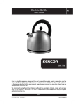
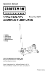
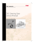
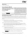
TRW Automotive
Commercial Steering Systems
Service Procedure #TAS-100
On-Vehicle Input Shaft Seal Replacement for
TAS/THP Series Steering Gears.
Service Kit #TAS000001
Revised July, 2005
CAUTION
Do not mix engine oil and ATF in the power steering system.
This TRW Commercial Steering Systems' service procedure
has been written to help you repair commercial vehicles
more efficiently. This procedure should not replace your
manuals; you should use them together. These materials are
intended for use by properly trained, professional mechanics,
NOT “Do-it-yourselfers”. You should not try to diagnose or
repair steering problems unless you have been trained, and
have the right equipment, tools and know-how to perform
the work correctly and safely.
Detecting Input Shaft Seal Leakage
TRW power steering gears incorporate an “Umbrella” style external dirt seal between the steering shaft U-joint and the housing of the steering
gear. The cavity under this seal is filled by TRW at assembly with a special grease to inhibit corrosion of the input shaft near the input shaft seal.
Since this “ Umbrella” does not positively interfere with the main housing, some amount of the grease under it can migrate to the external housing surfaces. Over time, especially under elevated operating temperatures, some of the base oil in the grease can separate from the carrier. This
thin film of oil can spread over the upper part of the gear, attract dust and dirt, causing the appearance that the input shaft seal is leaking power
steering fluid.
Initial inspection criteria to determine if the input shaft seal is leaking:
• If the dust/dirt in this area is “dry” (not saturated or not dripping fluid) the input shaft seal is operating properly.
• If it has not been necessary to replenish the reservoir fluid level frequently, the input shaft seal is operating properly.
• If the dust /dirt is “Wet” or appears as “caked mud” then a closer look is required.
Additionally, the following are other causes that may present false indications of input shaft seal leakage.
• Look for signs of over-greasing the U-joint yoke (which can spread to the input shaft seal of the steering gear over time, creating an
appearance of leakage), leaking power steering hoses (they are usually covered with a “wet mud” when the rubber part starts to fail).
• Oil leaks can occur at the hose fittings which give a false indication of a steering gear input shaft seal leak.
• On many vehicles, the reservoir is located directly over the steering gear. Overfilled or leaking reservoirs can drip onto the steering gear
resulting in a false indication of an input shaft seal leak.
In order to determine if the input shaft seal is leaking, do the following:
1. Wipe down the area of the steering gear around the input shaft seal and hose connections. DO NOT STEAM CLEAN OR USE A
POWER WASHER TO CLEAN THE STEERING GEAR.
2. With the vehicle parked and a temperature gauge inserted in the reservoir, observe the input shaft seal area and hose connections
while running the engine and steering the vehicle for 5-10 minutes. The oil temperature should be 130° - 160°F when observing
seal area and hose connections.
CAUTION
Do not let oil temperature exceed 250° F while performing this maneuver.
Conclusions:
• If fluid leakage is noted from the reservoir, hose, fittings, or other plumbing connections, repair the problem and retest.
•
If no fluid leakage is observed, then the appearance of leakage is likely a migration of grease not a seal failure.
1
Input Shaft Seal Replacement Procedure
This kit contains:
1 Retaining ring (401637)
1 Input shaft seal (478076)
3 Dirt & Water Seals (478044, 478060, 478050)
1 Grease Tube (406038) (Exxon Unirex 460)
2
Disconnect return
line
1.
Disconnect return line from the steering gear and plug the line.
Also cap the return port of the gear with a high pressure fitting.
Disconnect column
2.
Remove the steering column from the gear input shaft.
Remove dirt &
water seal
3.
Remove the dirt & water seal from the steering gear.
Remove retaining
ring
4.
Wipe out the grease and then remove the spiral retaining ring.
Use a screwdriver inserted into the notch formed in the end of
the ring.
Replace column
5.
Slip the steering column back onto the input shaft with the pinch
bolt installed, but not tightened.
Wrap exposed
area
6.
Tie or wrap a shop towel around the input shaft area and place a
drip pan under the vehicle to catch the oil.
Fill reservoir
7.
Add fluid as necessary to the fill line on the dipstick.
WARNING
Force out the seal
8.
DO NOT MIX FLUID TYPES.
See service manual for
recommended fluids.
With the vehicle in neutral, momentarily turn the starter (quickly
turn off the engine if it starts).
3
4
Remove input shaft
seal
9.
Remove the shop towel. Disconnect the steering column, and
remove the input shaft seal.
Inspect seal area
10.
Check the seal area of the valve housing for any seal fragments.
Remove any that are found.
Inspect old seal
11.
Check the seal for heat damage. If the seal is stiff and brittle,
and not pliable like the new seal, it is probably heat damaged.
You need to determine and fix the cause of excessive heat in the
vehicle.
Install new seal
12.
Put clean grease 406038 on the new input shaft seal and
place it over the input shaft, garter spring side first. Place seal
installer tool #J37073 over the input shaft and against the seal,
small diameter end first. Tap the seal installer tool until the tool
shoulder is square against the valve housing. Remove any seal
material that may have sheared off in the seal bore or retaining
ring groove.
Install retaining
ring
13.
Insert new retaining ring into the groove.
Install dirt & water
seal
14.
Pack the end of the valve housing bore around the input shaft
with grease 406038. Choose the correct size dirt & water seal by
comparing the choices to the old seal, or by measuring the major
diameter of the input shaft serrations (see chart below). Apply
more of grease 406038 to the new dirt & water seal and install
it over the input shaft. Seat it in the groove behind the serrations and against the valve housing.
Reconnect column
15.
Reconnect the steering column to the input shaft and tighten the
pinch bolt to torque level specified.
Reconnect return
line
16.
Reconnect the return line to the steering gear return port.
Continue by bleeding air from the system using the first procedure on page 6 for automatic bleed gears, and the second
procedure on page 6 for manual bleed gears.
Seal Part No.
478044
478060
478050
478050
Serration Size
13/16" x 36
7/8" x 36
1" x 36
1" x 79
Manual Bleed Screw
Major Serration Dia.
0.807 / 0.799
0.866 / 0.857
0.987 / 0.977
1.008 / 1.000
Auto Bleed Plug
Do Not Remove
5
Removing Air:
Automatic Bleed System
Removing Air:
Manual Bleed System
1.
Fill the reservoir nearly full.
1.
2.
Start and run the engine for 10 seconds, then shut it off.
Check and refill the reservoir. Repeat at least three times,
each time checking and refilling the reservoir.
Remove the air from a gear mounted in an inverted position and
equipped with a manual bleed screw by first following the air
bleeding procedure for an AUTOMATIC BLEED SYSTEM.
2.
With the engine idling and no steering action, loosen the
manual bleed screw about one turn, allowing air and aerated
fluid to “bleed out” around the bleed screw until only clear (non
aerated) fluid is observed. Then close the bleed screw and check
and refill the reservoir.
3.
Start the engine and let it idle for 2 minutes. Shut the engine
off and check the fluid level in the reservoir.
4.
Start the engine again. Steer the vehicle from full left to full
right several times. Add fluid, as necessary, to the full line
on the dipstick.
Repeat this procedure 3 or 4 times until only clear (non aerated)
fluid is discharged when the bleed screw is loosened.
3.
Torque the manual bleed screw to 27-33 lbf•in. (3.1-3.7 N•m).
Check and refill the reservoir.
NOTE
TRW Commercial Steering Systems
P.O. Box 60
Lafayette, IN 47902
Phone: 765.423.5377
Fax: 765.429.1868
6
Do not steer the vehicle while the bleed
screw is loose.