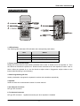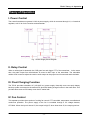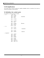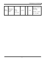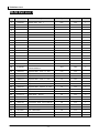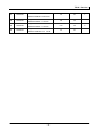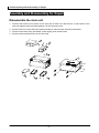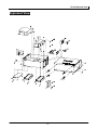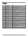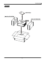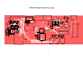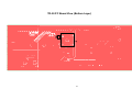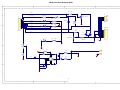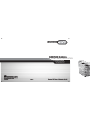
1
PORTABLE REPEATER
TR-50
Contents
General……………………………………………………………………………..1
Brief Introduction…………………………………………………………………..2
Theory of Operation………………………………………………………………4
Alignment & Calibration…………………………………………………………..6
Part List 1………………………………………………………………………….9
Assembly and Disassembly for Repair………………………………………11
Exploded View……………………………………………………………………12
Part List 2…………………………………………………………………………13
Packing……………………………………………………………………………14
PCB Board View…………………………………………………………………15
Schematic Diagram……………………………………………………………...17
Specifications…………………………………………………………………….19
TR-50 General
General
Manual Scope
This manual is intended for use by experienced technicians familiar with similar types of
communication equipment. It contains all service information required for the equipment and is current
as of the publication date.
User Safety Information
The following precautions are recommended for personnel safety:
z DO NOT transmit until all RF connectors are verified secure and any open connectors are
properly terminated.
z SHUT OFF and do not operate this equipment near electrical blasting caps or in an explosive
atmosphere.
z When in vehicles with an airbag, do not place a repeater in the area over an airbag or in the airbag
deployment area.
z DO NOT expose the repeater to direct sunlight for a long time nor place it close to a heating
source.
z DO NOT use any repeater with a damaged antenna. If a damaged antenna comes into contact
with your skin, a minor burn may result.
z This equipment should be serviced by a qualified technician only.
-1-
TR-50 Brief Introduction
Brief Introduction
1. LED Indicator
The following table indicates LED indication and corresponding radio status.
LED
Status
Red
Power on
Green
Receive (or in battery save mode)
Blue
Transmit
2. Power /Volume Control Knob
Rotate the Power/Volume Control Knob clockwise until a “click” is heard to turn the repeater on. Then
the LED turns red when the power is on. Rotate counter-clockwise to turn the repeater off until a “click” is
heard. When the repeater is on, turn the Knob to adjust volume. (Suggestion: adjust volume to the
lowest while Monitoring is unnecessary.)
3. RJ45 Programming I/O Port
Used by the dealer to program the repeater’s receiver and transmitter respectively.
4. Speaker
Used to monitor the communication status of current channel.
5. Rx Antenna Connector
N/F type RF connector.
6. Tx Antenna Connector
N/F type RF connector. Applied as antenna port when duplexer is installed.
-2-
TR-50 Brief Introduction
7. AC Power Inlet
After correctly connecting AC power supply, turn on the switch to enter AC power supply mode.
8. AC Power Switch
9. DC Power Inlet
The float charging function will operate in AC power supply mode with external gel cell batteries
connected. When AC mains power is lost, it will auto-revert to the back-up battery supply without
mechanical relay.
-3-
TR-50 Theory of Operation
Theory of Operation
I. Power Control
The control board draws a general 13.8V dc power supply, which is converted through U1, a 3-terminal
regulator, to 8.0V dc for the receiver and transmitter.
Fig. 1 Power Supply Block Diagram
II. Relay Control
When a valid signal is detected, the COR goes low and trigger PTT of the transmitter. At the same
time, the audio output from discriminator is routed to MIC input of the transmitter. The trimmable
resistor VR3 is used to adjust the receive audio output to the proper level for transmit audio deviation.
III. Float Charging Function
The TR-50 provides selectable AC (100-240V ac) power supply. Normally users can equip battery
back-up system connected to the external DC jack with floating charge function in the mean time. This
provides auto-revert to DC battery once the AC mains fails.
IV. Fan Control
This repeater provides three options of cooling fan control: PTT controlled, temperature controlled and
continuous operation. The power supply of the fan is controlled through a 5V voltage detector,
HT7050A. When the input is above 5V, the output is high-Z; when lower than 5V, the output goes low.
-4-
TR-50 Theory of Operation
V. AF Amplification
The receive audio is routed to another AF amplifier NJM386M, which is convenient for the users to
monitor the activities of current channel.
VI. Definition for control ports
The definition of all the pins goes as follows:
1. J3
1pin——NC
2pin——TLED3pin——MIC+
4pin——PTT
5pin——TLED+
6pin——RLED+
7pin——SP+
8pin——RLED9pin——Rx AF
10pin——COR
Transmitter
Receiver
2. J6
1pin——ETxD
2pin——ERxD
Transmitter
3pin——ATxD
4pin——ARxD
Receiver
3. RJ45 EXT
1pin——ARxD
2pin——MIC
3pin——ATxD
4pin——ERxD
5pin——GND
6pin——ETxD
7pin——EXT PTT
8pin——SB+(8V)
-5-
TR-50 Alignment & Calibration
Alignment & Calibration
I. Required Test Instrument
1.
DC power supply
1 set
1) Output range: 12~15 VDC (Minimum); output current: 3 A or more
2) Specified output: 13.8 VDC
3) The output should be stable, with minimal ripple & noise.
2. Ammeter
1 set
3. Digital voltmeter
1 set
4. Radio communication test set
1 set (with duplex function)
II. Test and Adjustment
1. Power supply
Measurement
Item
Condition
Adjustment
Specification/
Test
Instrument
Test Point
Part
Method
Remarks
Use ceramic
Digital
Voltmeter
DC output
voltage
DC output
terminal
Potentiometer
in Switch
power supply
adjuster to
adjust till the
voltage is
13.8±0.2V
within
requirement.
2. Power Supply for receiver and transmitter
Measurement
Item
Power Supply
Condition
Test
Instrument
Test Point
Digital
Voltmeter
VDD
-6-
Adjustment
Part
Method
VR1
Use ceramic
adjuster to
adjust VR1 till
the voltage is
within
requirement.
Specification/
Remarks
8.0±0.2V
TR-50 Alignment & Calibration
3. Relay Component (Note: Before adjustment, make sure the antenna (dummy load)
are properly connected and space-isolated)
Measurement
Item
Condition
Test
Instrument
Test
Point
Adjustment
Part
Specification/
Remarks
Method
Receiver:
1CH
455.0125MHz
2CH
455.0125MHz
CTCSS:67.0Hz
PC operation
3CH
system:
Operation
Frequency
WIN98SE
RJ45
/WIN2000
Programming
Programming
455.0125MHz
CDCSS:025
Transmitter:
port
1CH
software:
465.0125MHz
HT-50E
2CH
465.0125MHz
CTCSS:67.0Hz
3CH
465.0125MHz
CDCSS:025
Turn to CH1 and
enter duplex
mode. With
Use ceramic
Transmitter
adjuster to
Relay
connected to
BPF:0. 3~3KHz
deviation
“RF in” port and
AF OUT:
receiver to “Dual
1KHz/150mV
Antenna
VR3
rotate VR3
Frequency
until the
deviation:
deviation is
3.0±0.2KHz
out” port. Align
within
the output of
requirement.
“RF GEN” to
455.0125MHz。
Turn to CH1,
press PTT key
on handheld
Tx Power
microphone to
Antenna
transmit (or
check Tx power
in duplex mode)
-7-
Check
Power Output:
4.5±0.5W
TR-50 Alignment & Calibration
Duplex
sensitivity
Turn to CH1,
and operate
in duplex
mode
BPF:0.
3~3KHz
AF OUT:
1KHz/150mV
Antenna
Check
Sensitivity squelch on
transceiver:
-119±3dBm
Sensitivity squelch
off: -120±3dBm
-8-
TR-50 Part List 1
TR-50 Part List 1
No.
Part No.
Description
Ref. Symbol.
Location
Sum.
1
01031002
Resistor 0603
10Ω J
R20
T1B
1
2
01033932
Resistor 0603
39KΩ J
R17
T1B
1
3
01051022
Resistor 0805
1KΩ J
R3
T3B
1
4
01051032
Resistor 0805
10KΩ J
R11
T1A
5
01051032
Resistor 0805
10KΩ J
R6
T4A
6
01051032
Resistor 0805
10KΩ J
R16
T1B
7
01051202
Resistor 0805
12Ω J
R21
T1B
8
01051202
Resistor 0805
12Ω J
R18
T3C
9
01051202
Resistor 0805
12Ω J
R19
T1B
3
10
01051222
Resistor 0805
1.2KΩ
R14
T5C
1
11
01051532
Resistor 0805
15KΩ J
R7
T4A
1
12
01052022
Resistor 0805
2KΩ
J
R9
T2A
1
13
01053022
Resistor 0805
3KΩ
J
R22
T1A
14
01053022
Resistor 0805
3KΩ
J
R10
T2A
2
15
01054712
Resistor 0805
470Ω J
R4
T4B
1
16
01055122
Resistor 0805
5.1KΩ J
R5
T4B
1
17
01061022
Resistor 1206
1KΩ
R8
T5A
1
18
0122473H
VR1
T3B
1
19
02051043
Capacitor 0805
0.1uF
K 25V
C10
T1B
20
02051043
Capacitor 0805
0.1uF
K 25V
C11
T1B
21
02054713
Capacitor 0805
470P
K
50V
C1
T4B
22
02054713
Capacitor 0805
470P
K
50V
C2
T5A
23
02054713
Capacitor 0805
470P
K
50V
C5
T4A
24
02054713
Capacitor 0805
470P
K
50V
C6
T4A
4
25
02054733
Capacitor 0805
0.047uF
C9
T1B
1
26
02054743
Capacitor 0805
0.47uF
C7
T1B
1
27
0417AV70
Double diode
BAV70
D4
T5A
28
0417AV70
Double diode
BAV70
D8
T1B
2
29
0417AW56
Double diode
BAW56
D2
T2A
1
30
0501798D
PNP 2SB798-T1(DK)
Q3
T5A
1
31
0506114E
Bias Resistor, NPN DTC114EE(TL)
Q5
T1A
1
32
05173906
PNP MMBT3906
Q2
T5A
33
05173906
PNP MMBT3906
Q4
T5A
34
05173906
PNP MMBT3906
Q6
T1A
3
35
07LM3860
OP Amp NJM386M
IC2
T1B
1
36
18002802
TR-50 CNPCB
Trimmable resistor
J
J
47KΩ
MVR22HXBRN473
K 25V
K
16V
FR4 1.2T/2L/1
-9-
3
2
1
TR-50 Part List 1
37
T0610155
38
T0616106
39
T0616106
40
T0635104
1206
TMCSA1A155MTR.1.5UF/10V.M
Ta-capacitor1206
TMCMA1C106MTR 10uF 16V
Ta-capacitor1206
TMCMA1C106MTR 10uF 16V
Ta-capacitor1206
TMCSA1V104MTR.0.1uF
35V.M
- 10 -
C3
T3C
C8
T1B
C13
T1B
C4
T3C
1
2
TR-50 Assembly and Disassembly for Repair
Assembly and Disassembly for Repair
Disassemble the main unit
1.
Remove with tool the four screws on the rear side of main unit, and the four on the bottom of the
main unit together with the rubber gasket. Pull out the outer cover.
2. Remove the four screws fixing the duplexer and then remove those fixing the transceiver.
3. Remove the screws fixing transmitter, power supply, and control board.
4. Remove the accessories such as fan and Jack.
- 11 -
TR-50 Exploded View
Exploded View
- 12 -
TR-50 Part List 2
Part List 2
No.
Material Name
Material No.
1
14090360
M3×6 Screw (zinc-plated, black)
2
1413200A
TR50 Cover
3
1613000A
TR50 Rubber foot mat
4
14090360
M3×6 Screw ( zinc-plated, black)
5
14090420
Screw M4×20
6
19130030
Fan 12V 0.17A
7
14052010
Machine Screw M2×10 (zinc-plated, color)
8
0050107100
Transmitter
9
14052010
Machine Screw M2×10 (zinc-plated, color)
10
0050107100
Receiver
11
14090360
M3×6 Screw (zinc-plated, black)
12
0950100710
TR50 Control Board
13
1413201A
TR50 Machine case
14
1513000A
TR50 Knob (vol)
15
1713008A
Sponge gasket (SP)
16
13130805
Speaker
17
1713009A
Fast bar washer
18
14026010
Screw M3×6
19
1904020A
MC-500N Switching power supply
20
14090360
M3×6 Screw ( zinc-plated, black)
21
14090360
M3×6 Screw ( zinc-plated, black)
22
08MODUP10000
TR-50 duplexer
23
14090430
M4 Hex nut
24
14090360
M3×6 Screw (zinc-plated, black)
25
08130002
Antenna receptacle (Tx)
26
08130002
Antenna receptacle (Rx)
27
14040360
M3×6 Screw (flat head)
28
08130006
AC receptacle
29
1904019A
AC Switch
30
08131102
DC Jack
- 13 -
TR-50 Packing
Packing
- 14 -
TR-50 PC Board View (Top Layer)
15
TR-50 PC Board View (Bottom Layer)
16
TR-50 Schematic Diagram (RIC)
1
2
4
3
2
R11 10K
COR
J3
10
9
8
7
6
5
4
3
2
1
1
D5
R12
2
RLED-
J6
VR3 47K
R22 39K
RX AF OUT
12Ω
C7
0.47uF
1
R23
0Ω
NU
RLED+
D6
2
TLED-
1
TLED+
R15
12Ω
R13
12Ω
Q5
DTC114EUA
1
2
3
4
3
D
D
ETxD
ERxD
ATxD
ARxD
CON4
GND
GND
RJ45
. EXT.
NC
R16
10K
PTT
CON10
1
2
3
4
5
6
7
8
EXT MIC
MIC
D8
BAV70
1
C
Q6
2
GND
MMBT3906
D7
1
EXT PTT
1.2K
R17
10K(47K)
3
2
R14
C
8V
8V
SW1
10K
GND
R19
12Ω
+
R18
C8
10uF
C10 0.1uF
+
5
-
B
0.047uF
IC2
3
7
2
SP+
C9
C12
R21
220uF
12Ω
GND
GND
+
12Ω
GND
SP-
10Ω
6
1
B
SP+
R20
13V
4
8
NJM386M
C13 10uF
HYT Science & Technology Co.,Ltd
C11 0.1uF
TR-50
MODEL NAME
GND
PART NAME
A
PAGE
REPEATER INTERFACE COMMUNICATION BOARD
DATE
FILE NO.
17
1
2
2 OF 2
A
REV
R. Leung
DRAWN BY
3
CHECKED
APPROVAL
2
4
00
TR-50 Schematic Diagram (Power Management Board)
1
2
F1
J2
1
2
3A
Q1
PSS8550D
0.22Ω/2W
12V
3
D
CON2
GND
U1
LM317T
+
-
1
3
VIN
R1
D1
KBPC606
1
C1
+
470pF
Q2
CON3
C4
3
D
1
2
3
C3
0.1uF
2
1
2
3
R3
270Ω
1
470pF
8V
CON3
J4
2
C2
2
VOUT
J5
SW1
ADJ
+
4
DC 13.8V
4
3
+
VR1
MMBT3906
1.5uF/10V
10K
R2
1KΩ/2W
GND
D2
C
1
GND
2
PTT
R4
BAW56
R10
2K
3K
470Ω
VR2
2
9.1V / 1A
3
J1
C5
470p
R6
CON2
GND
BAV70
C6
470p
IC1 HT7050A
2
VDD
OUT
GND
R7
Q4
1
1
MMBT3906
B
GND
15K
R8
1K (1/4W)
3
6
5
4
VSS
B
1
2
D4
10K
5.1K
3
2
1
3
2
1
R5
6
5
4
Q3
2SB798
D3
10K 负温
JP1
CONN SOCKET 3x2
GND
1
R9
GND
2
C
3
3
GND
GND
HYT Science & Technology Co.,Ltd
MODEL NAME
TR-50
PAGE
PART NAME
POWER MANAGEMENT BOARD
DATE
A
FILE NO.
18
1
2
1
R. Leung
3
CHECKED
APPROVAL
4
2
June, 2004
REV
DRAWN BY
OF
00
A
TR-50 Specifications
Specifications
146.0000MHz-174.0000MHz
Frequency Range
440.0000MHz-470.0000MHz
Channel
1
Frequency Capacity
≤±5PPM
Valid Transmit Power
≤5W
Transmitter Spurious Radiation
≤50uW
Modulation Limit
± 5.0KHz
Occupied Bandwidth
≤8.5KHz
Adjacent Channel Power Rejection
≥55dB
Modulation AF Distortion
≤5%
≤0.3uV (12dB SINAD)
Receive Sensitivity
Co-channel Rejection
≥-8dB
Blocking
≥85dB
Inter-modulation Rejection
≥50dB
Adjacent Channel Selectivity
≥50dB
Receiver Spurious Radiation
≤20nW
Receive AF Distortion
≤5%
- 19 -