1
Site Installation and
Maintenance Guide
Hardware: Cartridge Tapes
REFERENCE
77 A7 62UP 00
DPS7000/XTA
NOVASCALE 7000
CTS 9460
DPS7000/XTA
NOVASCALE 7000
CTS 9460
Site Installation and Maintenance
Guide
Hardware: Cartridge Tapes
November 1998
BULL CEDOC
357 AVENUE PATTON
B.P.20845
49008 ANGERS CEDEX 01
FRANCE
REFERENCE
77 A7 62UP 00
The following copyright notice protects this book under Copyright laws which prohibit such actions as, but not
limited to, copying, distributing, modifying, and making derivative works.
Copyright
Bull SAS 1998
Printed in France
Suggestions and criticisms concerning the form, content, and presentation of this
book are invited. A form is provided at the end of this book for this purpose.
To order additional copies of this book or other Bull Technical Publications, you
are invited to use the Ordering Form also provided at the end of this book.
Trademarks and Acknowledgements
We acknowledge the right of proprietors of trademarks mentioned in this book.
Intel® and Itanium® are registered trademarks of Intel Corporation.
Windows® and Microsoft® software are registered trademarks of Microsoft Corporation.
UNIX® is a registered trademark in the United States of America and other countries licensed exclusively through
the Open Group.
Linux® is a registered trademark of Linus Torvalds.
The information in this document is subject to change without notice. Bull will not be liable for errors contained
herein, or for incidental or consequential damages in connection with the use of this material.
Preface
Scope and
Objectives
This manual is designed to assist Bull Support Engineers in installing and
maintaining the CTS 9490 cartridge subsystem at customer sites. This subsystem
is also known as TimberLine and CTC D001. In this manual, these names are used
interchangeably.
This guide does not replace the installation and maintenance documentation
supplied with the individual components of the subsystem. The guide supplements
the existing documentation and explains how to connect the subsystem to
DPS 7000 systems via an ACSLS server.
The manual also gives an overview of the subsystem components and references
specific product documentation where appropriate.
Intended
Readers
To achieve maximum benefit the procedures, design requirements, suggested
parameters and recommendations in this manual should be observed, as this will
ease future maintenance. A successful subsystem installation also depends on how
individual responsibilities are allocated and how overall planning and follow-up
work are performed.
A technical publication remarks form is provided at the end of this manual for use
by the reader to notify Bull of errors in the manual, or to offer suggestions for its
improvement.
77 A7 62UP Rev00
iii
CTS 9490 Installation and Maintenance Guide
Structure
Bibliography
The structure of this manual is as follows:
Chapter 1
Product Overview: introduces the CTS 9490 cartridge
subsystem and the connection architecture.
Chapter 2
Preparing for Installation: details the tools required
for installation and the connection cables and adapters
required for the connection architecture.
Chapter 3
Installation: gives step by step instructions for
installing, connecting and testing the CTS 9490.
Chapter 4
Maintenance: explains how to support the cartridge
subsystem and gives details of remote maintenance
capabilities.
Chapter 5
Reporting: explains how to report on installation and
maintenance tasks.
Appendix A
Returned Data and Messages: explains how to
analyze the PRLOG and the results of log and request
sense.
The following manuals discuss related subjects:
Bull Manuals:
ESTRELLA Series 200 System Installation Guide....................................86 A1 17AT
ESTRELLA Series 300 System Installation Guide...................................86 A1 06HX
MIC User Guide ..................................................................................... 77 A7 75UU
MARS Plus General Information and Installation .........................CSS/ESS/95FW37
CTS 9490 Cartridge Subsystem Site Preparation Guide........................ 00 A1 41UU
StorageTek Manuals:
9490 Cartridge Subsystem PN Compatibility Listing......................... STK P/N: 4929
9490 and SD3 Cartridge Subsystem Diagnostic Guide...................... STK P/N: 9632
................................................................................................................(308771801)
9490 Cartridge Subsystem Illustrated Parts Catalogue..................... STK P/N: 9633
9490 Cartridge Subsystem Service Manual........................................ STK P/N: 9635
................................................................................................................(310710401)
9490 Cartridge Subsystem Installation Manual ................................. STK P/N: 9636
9490 Cartridge Subsystem Technical Reference Manual ................... STK P/N: 9638
................................................................................................................(310710501)
9490 Cartridge Subsystem Operator's Guide..................................... STK P/N: 9634
iv
77 A7 62UP Rev00
Table of Contents
1.
2.
3.
Product Overview
1.1
Introduction ..................................................................................................................... 1-1
1.2
The UNIX Server............................................................................................................. 1-1
1.3
Product Technology ........................................................................................................ 1-2
1.4
Connection Interface ....................................................................................................... 1-4
1.5
Software Architecture...................................................................................................... 1-5
Preparing for Installation
2.1
Tools Required................................................................................................................ 2-1
2.2
Unpacking and Checking ................................................................................................ 2-2
2.3
Cables ............................................................................................................................. 2-2
2.4
Additional Controllers and Drivers .................................................................................. 2-2
Installation
3.1
Overview ......................................................................................................................... 3-1
3.2
Install and Set up Cartridge Subsystem.......................................................................... 3-2
3.3
Verify UNIX Server.......................................................................................................... 3-3
3.4
Install System (ACSLS only)........................................................................................... 3-4
3.4.1 Types of Installation........................................................................................... 3-4
3.4.1.1 Mono Installation - Single Access ..................................................... 3-4
3.4.1.2 Mono Installation - Dual Access........................................................ 3-5
3.4.1.3 Dual Installation - Coupled Access ................................................... 3-6
3.4.2 Installation Process Overview ........................................................................... 3-7
3.4.2.1 System Configuration Generation ..................................................... 3-7
3.4.2.2 Power off the System and Subsystem .............................................. 3-8
3.4.2.3 Install the WSP Board(s) ................................................................... 3-8
3.4.2.4 Connect the SCSI Cable(s) on the WSP Board(s)............................ 3-8
3.4.3 Examples ........................................................................................................... 3-9
77 A7 62UP Rev00
v
CTS 9490 Installation and Maintenance Guide
3.4.3.1
3.4.3.2
3.4.3.3
3.4.3.4
4.
vi
Mono Installation - Single Access ..................................................... 3-9
Example Mono Installation - Dual Access....................................... 3-11
Example Dual Installation - Coupled Access .................................. 3-14
Example Sysout Report for Mono Installation - Dual Access ......... 3-17
3.5
Configure the Library .................................................................................................... 3-17
3.6
Connect and Test the ACSLS System.......................................................................... 3-18
3.6.1 Making the ACSLS Connection ....................................................................... 3-18
3.6.2 Configuring the System ................................................................................... 3-18
3.6.2.1 Power on the System and Subsystem ............................................ 3-18
3.6.2.2 Update the CPSF ............................................................................ 3-19
3.6.2.3 Perform the INIT IND, RESTORE, CONFIG, RESTORE,
RESTART (COLD) .......................................................................... 3-19
3.6.2.4 Perform a MIC remake .................................................................... 3-19
3.6.3 Performing the OLTDs..................................................................................... 3-19
3.6.3.1 Host System .................................................................................... 3-19
3.6.3.2 ACSLS Connection ......................................................................... 3-21
Maintenance
4.1
Maintenance Strategy ..................................................................................................... 4-1
4.2
Predictive Maintenance................................................................................................... 4-2
4.3
Programmed Maintenance.............................................................................................. 4-2
4.3.1 UNIX Server....................................................................................................... 4-2
4.3.2 CTC D001 (CTS 9490) ...................................................................................... 4-2
4.4
Partnership Maintenance ................................................................................................ 4-3
4.4.1 Initialization of Call............................................................................................. 4-3
4.4.2 Remote Maintenance......................................................................................... 4-3
4.5
Preventive Maintenance ................................................................................................. 4-4
4.6
Maintenance Teams........................................................................................................ 4-5
4.6.1 Organization of Maintenance Teams................................................................. 4-5
4.6.2 Remote Specialists ............................................................................................ 4-6
4.6.3 Product Specialists ............................................................................................ 4-6
4.6.4 Intervention Scenario......................................................................................... 4-7
4.7
Maintenance Tools.......................................................................................................... 4-8
4.7.1 CTC D001 (CTS 9490) ...................................................................................... 4-8
4.7.2 DPX/20 and Estrella Maintenance Tools........................................................... 4-8
4.7.3 Other Tools ........................................................................................................ 4-8
4.8
Spare Parts Strategy....................................................................................................... 4-9
4.8.1 Repair Strategy.................................................................................................. 4-9
4.8.2 Spare Parts List ................................................................................................. 4-9
4.9
Consumables .................................................................................................................. 4-9
77 A7 62UP Rev00
5.
A.
Reporting
5.1
Installation and Maintenance Reporting.......................................................................... 5-1
5.2
Assessment..................................................................................................................... 5-2
5.2.1 Field Performance Evaluation (FPE) ................................................................. 5-2
5.2.2 Quality Measurement......................................................................................... 5-2
Returned Data and Messages
A.1
PRLOG Analysis .............................................................................................................A-1
A.1.1 Channel Exceptions...........................................................................................A-1
A.1.2 I/O Errors ...........................................................................................................A-4
A.1.2.1 PSB/DSB Termination Reports .........................................................A-5
A.1.2.2 Detailed Status for All TCA Sub-Systems .........................................A-8
A.1.2.3 CTC D001 (CTS 9490) Specific DSBs............................................A-10
A.2
Triggering Remote Control (Telecontrol) ......................................................................A-19
A.2.1 All TCA Sub-Systems ......................................................................................A-19
A.2.2 CTC D001 (CTS 9490 - TimberLine)...............................................................A-19
A.2.2.1 Formatter Errors ..............................................................................A-19
A.2.2.2 Statistics ..........................................................................................A-20
A.3
Request Sense Results ................................................................................................A-21
A.4
DSC Meanings ..............................................................................................................A-28
A.5
Log Sense Results ........................................................................................................A-32
A.6
OLTDS ..........................................................................................................................A-36
Glossary
Index
77 A7 62UP Rev00
vii
CTS 9490 Installation and Maintenance Guide
Table of Graphics
Figures
1-1.
1-2.
3-1.
3-2.
3-3.
4-1.
4-2.
4-3.
Major Components of an M34 Cartridge Drive ............................................................... 1-3
Software Associated with the ACSLS Connection Architecture ..................................... 1-5
Mono Installation - Single Access ................................................................................... 3-4
Mono Installation, Dual Access....................................................................................... 3-5
Dual Installation - Coupled Access ................................................................................. 3-6
Maintenance Strategy ..................................................................................................... 4-1
Organization of Maintenance Teams .............................................................................. 4-5
Maintenance Intervention Scenario ................................................................................ 4-7
Tables
1-1.
2-1.
3-1.
3-2.
A-1.
A-2.
A-3.
A-4.
A-5.
A-6.
viii
Software Versions for the ACSLS Connection Architecture ........................................... 1-5
Logic Cables for ACSLS Architecture ............................................................................. 2-2
Cables for ACSLS Connection........................................................................................ 3-3
SCSI Controller Cards .................................................................................................... 3-3
Sense Request Data Returned .....................................................................................A-21
Request Sense EOM Positions.....................................................................................A-22
Sense Key Codes .........................................................................................................A-23
ASC and ASCQ of Request Sense(1/2) .......................................................................A-25
Byte 20 DSC Meanings (1/4) ........................................................................................A-28
Log Sense Data (1/4) ....................................................................................................A-32
77 A7 62UP Rev00
1. Product Overview
1.1
Introduction
The StorageTek 9490 Cartridge Subsystem (also known as TimberLine and CTC
D001) is a high-performance information storage and retrieval system that uses
both the Enhanced Capacity cartridge tape (E-Cartridge, also known as E-Tape)
and standard length cartridges used in 18-track cartridge subsystem as the storage
medium. It is already proposed in ESCON/GCOS 8 and SCSI/AIX connections,
and will be proposed by DPS 7000 product line as new offer to be connected on
existing or new libraries. In this document, you will find only information relative
to the DPS 7000 connection.
1.2
The UNIX Server
For an ACSLS connection the following UNIX servers are available:
• DPX/20 model 155,*
• DPX/20 model 215,*
• Estrella MT 604,
• Estrella 340.
* NOTE:
will be replaced by new one, year 2000 compliant.
77 A7 62UP Rev00
1-1
CTS 9490 Installation and Maintenance Guide
1.3
Product Technology
The CTC D001 Cartridge Subsystem supports three tape-recording formats:
• 36-track, extended (read and write)
• 18-track, extended (read only)
• 18-track, standard (read only).
All three recording formats are compatible with the ANSI and ECMA
specifications.
A CTC D001 Cartridge Subsystem consists of 1 -> 12 cartridge drives (CDs), with
a maximum of 24 controller transport units (CTUs), that the subsystem support unit
(SSU) communicates with.
CDs are available in three models:
• M32, which contains two CTUs in a single frame.
• M34, which contains four CTUs in a single frame.
• M44, which contains four CTUs and four cartridge scratch loaders (CSLs) in a
single frame (not offered for the DPS 7000 connection).
The CTC D001 Cartridge Subsystem will be connected to the DPS 7000 through a
SCSI-2 Interface, capable of transferring data over a wide SCSI bus at 20 MB/s
(subsystem capability).
It also offers an IBM Enterprise System Connection (ESCON) interface, that will
not be used in this case.
The subsystem support unit (SSU) is an independent unit that stores the
maintenance, functional and diagnostic microcodes on a hard disk and downloads
the code to the CTU during the initial program load (IPL). The SSU communicates
with all CTUs in the cartridge subsystem over a thin-wire, Ethernet, local area
network (LAN). The SSU also records performance, events, and diagnostic
statistics and stores that information on the hard drive.
The CTC D001 Cartridge Subsystem can be installed in one of four configurations:
• Stand-alone or manual mount (M32 and M34 - not offered for DPS 7000
connection).
• Stand-alone with an optional CSLs (M32 - not offered for DPS 7000
connection).
• Stand-alone with four CSLs (M44 - not offered for DPS 7000 connection).
• Attached to an automated cartridge subsystem (ACS) such as StorageTek's
NearLine (4410/9310 models), WolfCreek (9360 model), or TimberWolf (9740
model) libraries (M32 or M34).
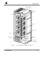
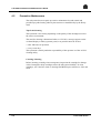
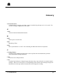
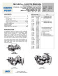
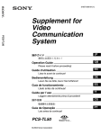
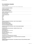
A view of the M34 cartridge drive is shown in Figure 1-1.
1-2
77 A7 62UP Rev00
Product Overview
O v erh ead D isp lay
attach es h ere
U p p er
B lo w er
SSU
SCSI
P o rts
C o n tro ller
T ran sp o rt
L o w er
B lo w er
D C P o w er
S u p p lies
A C P o w er
S u p p ly
(b eh in d lo w er)
Figure 1-1.
77 A7 62UP Rev00
Major Components of an M34 Cartridge Drive
1-3
CTS 9490 Installation and Maintenance Guide
1.4
Connection Interface
Connection to DPS 7000 will be done through differential SCSI-2 interface (ANSI
standards compliant).
Synchronous transfers are negotiated between the target and the initiator to obtain
the optimal rate of transfer that includes fast and wide (16-bit) transfers at rates of
up to 20 MB/s.
Asynchronous transfers are the physical transfer of data without a regular or
predictable timing relationship following an I/O request.
The SCSI-2 differential alternative has the following characteristics:
• maximum cable length of 25 meters (82 feet),
• minimum cable length of 0.3 meters (12 inches),
• low and high noise rejection,
• elimination of ground loops,
• improved signal quality over the single-ended alternative,
• performs a full parity check on all bus transfer operations,
• uses either the SCSI-3 « P-cable » or the SCSI-2 « A-cable » with an adapter.
All signals will be terminated at each end of the SCSI bus.
The CTC D001 Cartridge Subsystem has the option to supply terminator power.
1-4
77 A7 62UP Rev00
Product Overview
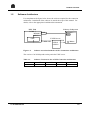
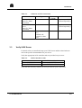
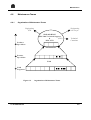
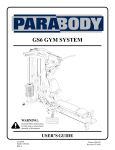
1.5
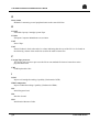
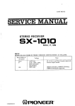
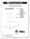
Software Architecture
For completeness the figure below shows the software required for the connection
architecture. Installation of the software is outside the scope of this manual. For
details, refer to the appropriate installation documentation.
L ib ra ry S u b sy stem
D P S 7 00 0
GCOS 7
W SP
DVMGT
O PEN 7
D rives
U N IX S erver
CLX
ETHERNET
Figure 1-2.
SC SI
A IX &
ACSLS
R obot
Software Associated with the ACSLS Connection Architecture
The version of ACSLS depends on the particular UNIX server.
Table 1-1.
Server
Estrella
77 A7 62UP Rev00
Software Versions for the ACSLS Connection Architecture
AIX
4.2 or later
ACSLS
5.1.1
CLX
3.2
OPEN 7
V4.2
1-5
CTS 9490 Installation and Maintenance Guide
❑
1-6
77 A7 62UP Rev00
2. Preparing for Installation
2.1
Tools Required
This section details the physical tools you require for installation and maintenance.
• Static protection wrist band.
This must be used when repairing or testing the CTC D001 (CTS 9490) alone or
in conjunction with the "Static Protective Field Service Kit" provided in the
"open me first" of Vega/Auriga Systems.
• CRS Tool Kit (Torx Driver Set).
This is useful for maintenance purposes.
• Laptop Computer
You need this to:
− install the microcode in the subsystem.
− configure the subsystem.
− update the Time-Of-Day clock of the subsystem.
− test the subsystem.
− display FSCs, FRUs and performance statistics of the subsystem.
− examine event and diagnostic logs of the subsystem.
− enter the maintenance device environment to maintain the subsystem.
• Auto-answer modem.
You use this to accomplish a remote hook-up through a serial CCITT cable with
an RJ-45 connector for the LSM connection.
CCITT modular cable assemblies are available for connecting the adapter to the
Machine Activated Routing Switch (MARS).
•
•
•
•
•
•
•
•
77 A7 62UP Rev00
Phillips screwdriver
Torx screwdriver
Screwdriver
7mm wrench
Cutting pliers
Flat pliers
Set of Allen Keys
Multimeter
2-1
CTS 9490 Installation and Maintenance Guide
2.2
Unpacking and Checking
For detailed instructions on unpacking the CTC D001 (CTS 9490) refer to the
specific product installation documentation.
NOTE:
The temperature and humidity of the data cartridges must be allowed to
stabilize in the specific ambient environment for 24 hours.
2.3
Cables
The logic connection cables you require are shown in the following table:
Table 2-1.
From
WSP
UNIX Server
2.4
Logic Cables for ACSLS Architecture
To
Drives
Library
Cable
SCSI cable, either 10m or 20m.
SCSI cable 20m.
Additional Controllers and Drivers
If the installation is a new system, not an upgrade, the server is delivered from the
factory pre-fitted with the following SCSI interface cards:
Interphase DE cards are supplied in Estrella servers.
If you are installing onto existing servers, check the appropriate cards are available
in the machines. Note that Corvette cards are supplied in the DPX/20 server.
Ensure you have the correct number of WSP cards for the DPS 7000 hosts to
support the number of tape drives you are installing. For details refer to the System
Configuration in Section 3.
2-2
77 A7 62UP Rev00
3. Installation
3.1
Overview
Installation of the cartridge subsystem has the following distinct stages:
• Install and Set Up Cartridge Subsystem
See paragraph 3.2.
• Verify UNIX Server
See paragraph 3.3.
• Install System (ACSLS only)
See paragraph 3.4.
• Configure the Library
See paragraph 3.5.
• Connect and Test The ACSLS System
See paragraph 3.6.
77 A7 62UP Rev00
3-1
CTS 9490 Installation and Maintenance Guide
3.2
Install and Set up Cartridge Subsystem
Installation of the subsystem is detailed in the StorageTek 9490 Cartridge
Subsystem Installation Manual.
The step by step check list below serves as a reminder. Where appropriate step
descriptions in this document include additional procedures required to prepare for
connecting with an ACSLS server.
At CTL 9490 level before powering-on
The specific installation for the DPS 7000 consists of:
•
•
•
•
•
•
•
•
•
•
•
•
•
•
•
•
unpacking the Cartridge Drives,
preparing the Cartridge Drives for attachment to the library,
ensuring there is enough Cooling,
installing the Operator Panel Cables,
inspecting the 9490 Cartridge Subsystem,
attaching the Cartridge Drive to the library,
preparing the Air Box,
installing the Air Box,
installing the Overhead Display (if any),
inserting the Overhead Display Guide (if necessary),
connecting LAN Cables,
setting the LAN Address,
installing SCSI-2 cables,
connecting the M.A.R.S. Box,
installing and configuring the remote maintenance modem,
connecting AC Power.
The duration is between 2 and 3 hours, depending on the configuration ordered.
For further details, refer to the StorageTek 9490 Cartridge Subsystem Installation
Manual.
3-2
77 A7 62UP Rev00
Installation
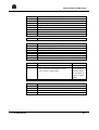
Table 3-1.
Cables for ACSLS Connection
Connection
DPS 7000 direct
to the CTC D001
(CTS 9490)
UNIX ACSLS
Server
to the CTC D001
(CTS 9490)
Power
3.3
Type
SCSI
Maximum
Length
10 m or 20 m
Number
SCSI
20 m
1 per server
(ordered separately)
120-240 VAC
20 A
Standard wall
connector or bare
wires
3.0 m
1 per unit
1 per host per WSP
(ordered separately)
Verify UNIX Server
For details of how to install and setup your UNIX server and the related software
refer to the specific documentation for your server.
Verify the appropriate SCSI controller cards are provided on you server:
Table 3-2.
SCSI Controller Cards
DPX/20 215
ESTRELLA
SCSI Controller Card
CORVETTE
INTERPHASE DE
Verify that the necessary software has been provided on your UNIX server.
77 A7 62UP Rev00
3-3
CTS 9490 Installation and Maintenance Guide
3.4
Install System (ACSLS only)
Verify that you have the correct number of expansion buses and WSP cards. You
need 1 WSP per MFB. A WSP can support up to 2 CTC D001s (CTS 9490s), see
Types of Installation below for more details.
3.4.1
Types of Installation
The following installations are possible:
• mono installation - single access
• mono installation - dual access
• dual installation - coupled access
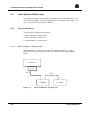
3.4.1.1
Mono Installation - Single Access
Mono installation - single access, is the most simple installation. A single
DPS 7000 host has a single access path to a CTC D001 (CTS 9490) as shown
below.
DPS7000
WSP
Port 0
SCSI
T
CTU 9490
Figure 3-1.
3-4
CTU 9490
Mono Installation - Single Access
77 A7 62UP Rev00
Installation
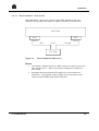
3.4.1.2
Mono Installation - Dual Access
Mono installation - dual access requires a single DPS 7000 host to have two
alternative access paths to the same CTC D001 (CTS 9490), as shown below:
D P S 7000
W SP
W SP
P o rt 0
P o rt 1
"O N "
SCSI
"S P A R E "
C T U 9490
Figure 3-2.
Mono Installation, Dual Access
NOTES:
77 A7 62UP Rev00
1.
The cabling is different for the two WSP boards. One card uses port 0, the
other card uses port 1. Refer to the System Configuration example for
more details.
2.
Remember that the maximum SCSI length is 25 m in total between
terminators. Consequently, in this example you are restricted to 10 m
cables between the DPS 7000 and the subsystem.
3-5
CTS 9490 Installation and Maintenance Guide
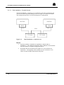
3.4.1.3
Dual Installation - Coupled Access
The Dual Installation - Coupled Access installation is the most complicated, and
involves two DPS 7000 hosts sharing access to a single CTC D001 (CTS 9490).
The example shown below is for the maximum drive configuration.
D P S 7000
D P S7000
W SP
W SP
P o rt 0
C T U 9490
Figure 3-3.
P o rt 1
SCSI
C T U 9490
Dual Installation - Coupled Access
NOTES:
3-6
1.
One host machine is identified as installation 0 and the other as
installation 1. The cabling for the WSP cards is different in each machine.
For more details see System Configuration below.
2.
Remember that the maximum SCSI length is 25 m in total between
terminators. Consequently in this example you are restricted to 10 m
cables between the DPS 7000 and the subsystem.
77 A7 62UP Rev00
Installation
3.4.2
Installation Process Overview
All three installations involve the following steps to set up the DPS 7000 host(s):
1.
System Configuration Generation under FGF: MNCONF, FIRMGEN,
BLOAD.
2.
Power off both system and library subsystem
3.
Install the WSP board(s)
4.
Connect the SCSI cable on the WSP board(s)
Total duration is about 2.5 hours.
NOTE:
The system takes the new configuration description into account after the
Configuring the System phase, when the physical connections are made.
3.4.2.1
System Configuration Generation
You generate the configuration files for the system(s) just once, for all the drives
together. You use the DPS 7000 console to do this.
• Launch FGF.
• Search for the name of the current configuration using "DFW".
• Run MNCONF.
• Execute "IOM" to get the system suggestion for the PX and slot to use. The
system gives you this, plus the computed load factors for each subsystem.
• Execute the new configuration description from within the current configuration,
using "MD". For this subsystem, the type of IOM is WSP-C, refer to "Examples"
below.
• Remember to execute "PR" to print the new configuration.
• Quit MNCONF.
• Run FIRMGEN with the new configuration.
• Run BLOAD with the new configuration on the system disk.
NOTE:
Be sure to save both the old and new configurations. If the new configuration
should fail, the old one can be recovered.
77 A7 62UP Rev00
3-7
CTS 9490 Installation and Maintenance Guide
3.4.2.2
Power off the System and Subsystem
Power off the subsystem: Turn off the AC switch.
Power off the system: Under SPV graphic, select POWER OFF.
3.4.2.3
Install the WSP Board(s)
Install the WSP board(s) into the slot(s) defined during configuration by
MNCONF.
3.4.2.4
Connect the SCSI Cable(s) on the WSP Board(s)
Connect the SCSI cable(s) on the WSP board(s). The results of MNCONF give the
active port on each board. Use this port for the connection.
Remember to label your cables.
NOTE:
In shared or dual access installations, the two WSP cards must use different
ports: one card uses port 0 and the other uses port 1.
3-8
77 A7 62UP Rev00
Installation
3.4.3
Examples
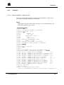
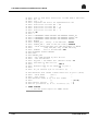
3.4.3.1
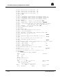
Mono Installation - Single Access
Below is a step-by-step example for adding a mono installation - single access
CTC D001 (CTS 9490) subsystem to an Artemis.
NOTE:
What appears in bold is what you have to type in. To accept the default value
offered in parentheses, type <enter>.
S0
S0
S0
S0
S0
S0
S0
S0
S0
S0
S0
S0
S0
S0
S0
S0
S0
S0
S0
S0
S0
S0
S0
S0
S0
S0
S0
S0
S0
S0
S0
S0
S0
S0
77 A7 62UP Rev00
LN03
LN03
LN03
LN03
LN03
LN03
LN03
LN03
LN03
LN03
LN03
LN03
LN03
LN03
LN03
LN03
LN03
LN03
LN03
LN03
LN03
LN03
LN03
LN03
LN03
LN03
LN03
LN03
LN03
LN03
LN03
LN03
LN03
LN03
IOMS
S: FGF
>>> WORKING LIBRARY : SYS.FW.SLLIB
>>>15:38 FGF
35.00
F: DFW
RELEASE - P1
TS = 44E
INSTAL_DATE = 94/12/13
EJR = 1
CONF = P76LSS
PREVIOUS CONFIGURATION = NONE
PREFIX = SYS.FW
FGF_VOL or BSR_VOLUME = H72A:MS/FSA
SYS_HUBVOL or BLOAD_VOLUME = S72A:MS/FSA
F:MNCONF
<<<15:39
>>>15:39 CONF 542.0
N:IOM
?
***MANDATORY VALUE MISSING FOR KEYWORD CONFIG_IN
IOM CONFIG + reference config.name
:P76LSS
NB_NCC + NUMBER OF NCC TO IMPLEMENT
(0):
NB_PSM1 + NUMBER OF PSM (STK,CMTS) to implement (0):
NB_PSM2 + NUMBER OF PSM with MSC4 to implement (0):
NB_PNM1 + NUMBER OF PNM with MPC to implement
(0):
NB_MSP1 + NUMBER OF PNM other to implement
(0):
NB_MSP2 + NUMBER OF WSP (WSP-C function)
(0): 1
NB_MSP3 + NUMBER OF MSP (MSP-C function)
(0):
NB_MSP2 + NUMBER OF MSP/WSP with one EXB10E
(0):
NB_MSP3 + NUMBER OF MSP/WSP with two EXB10E
(0):
NB_PRM + NUMBER OF PRM and CPM to implement
(0):
NB_PRM + NUMBER OF LNM to implement
(0):
N: IOM P76LSS
NB_MSP0=1
Configuration name: P76LSS
to be implemented in ADD-ON to your existing configuration
3-9
CTS 9490 Installation and Maintenance Guide
S0
S0
S0
S0
S0
S0
S0
S0
S0
S0
S0
S0
S0
S0
S0
S0
S0
S0
S0
S0
S0
S0
S0
S0
S0
S0
S0
S0
S0
S0
LN03
LN03
LN03
LN03
LN03
LN03
LN03
LN03
LN03
LN03
LN03
LN03
LN03
LN03
LN03
LN03
LN03
LN03
LN03
LN03
LN03
LN03
LN03
LN03
LN03
LN03
LN03
LN03
LN03
LN03
List of free PX(s) and slot(s) for WSP (WSP-C function):
Px : 03
Slot : 15
Computed load factor for implementation: 600
Load factor for IOSS #00 : 300
Load factor for IOSS #01 :
0
Load factor for IOSS #02 : 400
Load factor for IOSS #03 :
0
N: MD
?
***MANDATORY VALUE MISSING FOR KEYWORD CONFIG_IN
***MANDATORY VALUE MISSING FOR KEYWORD CONFIG_OUT
***MANDATORY VALUE MISSING FOR KEYWORD SELECT
MODIFY
CONFIG_IN + Config. to be modified :P76LSS
CONFIG_OUT + Name of the new config.:CONFSTK
Value authorized ALL, SYS, MSP,LSS,IOM,PC or DRIVE
(IOM, MSP,LSS) only if MB2 existing
SELECT+
Part to be modified::IOM
N:MODIFY P76LSS CONFSTK
IOM:
MODIFY_IOM
Only IOMs defined by this PX list
will be modified
PX_LIST + PX number list (decimal value)? 03
IOM name for PX03 Slot 15.
()
:WSP-C
External name for TC connected to port 0
()
:10
Do you confirm (Y,N or/ for exit? (Y)
:
S0
S0
S0
S0
S0
S0
S0
LN03
LN03
LN03
LN03
LN03
LN03
LN03
External SCSI linked to WSP-C PX03 slot 15 port 0 (TC10)
Drive model
(CT-3 )
:
Dual acces?
(0)
:
External names (1 up to 4 ext. names)
()
: (01 02)
Library option?
(0)
: 1
Do you confirm (Y, N or / for exit)? (Y) : Y
N: LABEL CONFSTK
--> See the sysout report for LABEL result
3-10
77 A7 62UP Rev00
Installation
3.4.3.2
Example Mono Installation - Dual Access
Below is a step-by-step example for adding a mono installation - dual access
CTC D001 (CTS 9490) subsystem to an Artemis.
NOTE:
What appears in bold is what you have to type in. To accept the default value
offered in parentheses, type <enter>.
S0
S0
S0
S0
S0
S0
S0
S0
S0
S0
S0
S0
S0
S0
S0
S0
S0
S0
S0
S0
S0
S0
S0
S0
S0
S0
S0
S0
S0
S0
S0
S0
S0
S0
S0
S0
S0
S0
77 A7 62UP Rev00
LN03
LN03
LN03
LN03
LN03
LN03
LN03
LN03
LN03
LN03
LN03
LN03
LN03
LN03
LN03
LN03
LN03
LN03
LN03
LN03
LN03
LN03
LN03
LN03
LN03
LN03
LN03
LN03
LN03
LN03
LN03
LN03
LN03
LN03
IOMS
LN03
LN03
LN03
LN03
S: FGF
>>> WORKING LIBRARY : SYS.FW.SLLIB
>>>15:38 FGF
35.00
F: DFW
RELEASE - P1
TS = 44E
INSTAL_DATE = 94/12/13
EJR = 1
CONF = ES1
PREVIOUS CONFIGURATION = NONE
PREFIX = SYS.FW
FGF_VOL or BSR_VOLUME = H72A:MS/FSA
SYS_HUBVOL or BLOAD_VOLUME = S72A:MS/FSA
F:MNCONF
<<<15:39
>>>15:39 CONF 542.0
N:IOM
?
***MANDATORY VALUE MISSING FOR KEYWORD CONFIG_IN
IOM CONFIG + reference config.name
:ES1
NB_NCC + NUMBER OF NCC TO IMPLEMENT (0):
NB_PSM1 + NUMBER OF PSM (STK,CMTS) to implement (0):
NB_PSM2 + NUMBER OF PSM with MSC4 to implement (0):
NB_PNM1 + NUMBER OF PNM with MPC to implement
(0):
NB_MSP1 + NUMBER OF PNM other to implement
(0):
NB_MSP2 + NUMBER OF WSP (WSP-C function)
(0): 2
NB_MSP3 + NUMBER OF MSP (MSP-C function)
(0):
NB_MSP2 + NUMBER OF MSP/WSP with one EXB10E
(0):
NB_MSP3 + NUMBER OF MSP/WSP with two EXB10E
(0):
NB_PRM + NUMBER OF PRM and CPM to implement
(0):
NB_PRM + NUMBER OF LNM to implement (0):
N: IOM ES1
NB_MSP0=1
Configuration name: ES1
to be implemented in ADD-ON to your existing configuration
List of free PX(s) and slot(s) for WSP (WSP-C function):
Px
: 03 13
Slot : 15 05
Computed load factor for implementation: 600
3-11
CTS 9490 Installation and Maintenance Guide
S0
S0
S0
S0
S0
S0
S0
S0
S0
S0
S0
S0
S0
S0
S0
S0
S0
S0
S0
S0
S0
S0
S0
S0
S0
S0
S0
S0
S0
S0
S0
S0
S0
S0
S0
S0
S0
N:
LN03 Load factor for IOSS #00 : 300
LN03 Load factor for IOSS #01 : 300
LN03 Load factor for IOSS #02 : 100
LN03 Load factor for IOSS #03 :
0
LN03 N: MD
LN03 ?
LN03 ***MANDATORY VALUE MISSING FOR KEYWORD CONFIG_IN
LN03 ***MANDATORY VALUE MISSING FOR KEYWORD CONFIG_OUT
LN03 ***MANDATORY VALUE MISSING FOR KEYWORD SELECT
LN03 MODIFY
LN03 CONFIG_IN + Config. to be modified :ES1
LN03 CONFIG_OUT + Name of the new config.:CONFSTK
LN03
Value authorized ALL, SYS, MSP,LSS,IOM,PC or DRIVE
LN03
(IOM, MSP,LSS) only if MB2 existing
LN03 SELECT+
Part to be modified::IOM
LN03 N: MODIFY ES1 CONFSTK
LN03 IOM:
LN03 MODIFY_IOM
LN03
Only IOMs defined by this PX list
LN03
will be modified
LN03 PX_LIST + PX number list (decimal value)? 03
LN03 IOM name for PX03 Slot 15.
LN03
()
: WSP-C
LN03 External name for TC connected to port x
LN03
()
: 01 10
LN03 Do you confirm (Y,N or/ for exit? (Y)
:
LN03 IOM name for PX13 Slot 05.
LN03
()
: WSP-C
LN03 External SCSI linked to WSP-C PX03 slot 15 port x (TC01)
LN03
Drive model
(CT-3 )
:
LN03
Dual acces?
(0)
: 1
LN03
Other instal?
(0)
:
LN03
2nd port TC name ( )
: 10
LN03 External names (1 up to 4 ext. names)
LN03
()
:(11 12)
LN03 Library option?
(0)
: 1
LN03 Do you confirm (Y, N or / for exit)? (Y)
:
pr CONFSTK
Configuration name: CONFSTK
8889
(128 Mb)
MU
2*64Mb
EPU
(01)
IPU
(00)
IO-MB2 (02 03 00 01)
PX iom (27 03 13)
MSP
PX27
Slot 19
port 0->MCK1
Rack (K) cab #01 (MCK1)
(PC5C)
FSA (K1 K2 K3 K4)
MCK ACCESS #1 LCN=(01-04)
WSP-C
PX03
Slot 15
port 0->TC01
SCSI
external
(TC01)
(PC0D)
3-12
77 A7 62UP Rev00
Installation
WSP-C
SCSI
CT-3
PX13
Slot 05
external
(TC10)
(11 12)
(TC01,TC10) LCN=(01-03)
port 1->TC10
(PC2F)
With library option
(PCFE)
AUSP
UC01
--> List of free PX(s) and slot() for IOM:
Px
: 02 12 01 11 00 10 23 33 22 32 21 31 20 30 14 04 15 05 16
06 17 07 34
Slot : 14 06 13 07 12 08 15 05 14 06 13 07 12 08 04 16 03 17 02
18 01 19 04
+++
PX
: 24 35 25 36 26 37
Slot : 16 03 17 02 18 01
Load factor for IOSS #00 : 300
Load factor for IOSS #01 : 300
Load factor for IOSS #02 : 100
Load factor for IOSS #03 :
0
N:
N: LABEL CONFSTK
--> See the sysout report for LABEL result
77 A7 62UP Rev00
3-13
CTS 9490 Installation and Maintenance Guide
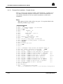
3.4.3.3
Example Dual Installation - Coupled Access
Below is a step-by-step example for adding a Dual Installation - Coupled Access
CTC D001 (CTS 9490) subsystem to an Artemis. You must run MNCONF on
each machine. Remember to call one machine installation 0, and the other
installation 1.
NOTE:
What appears in bold is what you have to type in. To accept the default value
offered in parentheses, type <enter>.
3-14
S0
S0
S0
S0
S0
S0
S0
S0
S0
S0
S0
S0
S0
S0
S0
S0
S0
S0
LN03
LN03
LN03
LN03
LN03
LN03
LN03
LN03
LN03
LN03
LN03
LN03
LN03
LN03
LN03
LN03
LN03
LN03
S: FGF
>>> WORKING LIBRARY : SYS.FW.SLLIB
>>>15:38 FGF
35.00
F: DFW
RELEASE - P1
TS = 44E
INSTAL_DATE = 94/12/13
EJR = 1
CONF = ESB2
PREVIOUS CONFIGURATION = NONE
PREFIX = SYS.FW
FGF_VOL or BSR_VOLUME = H72A:MS/FSA
SYS_HUBVOL or BLOAD_VOLUME = S72A:MS/FSA
F:MNCONF
<<<15:39
>>>15:39 CONF 542.0
N:IOM
?
S0
S0
S0
S0
S0
S0
S0
S0
S0
S0
S0
S0
S0
S0
S0
S0
LN03
LN03
LN03
LN03
LN03
LN03
LN03
LN03
LN03
LN03
LN03
LN03
LN03
LN03
LN03
LN03
IOMS
***MANDATORY VALUE MISSING FOR KEYWORD CONFIG_IN
IOM CONFIG + reference config.name
:ESB2
NB_NCC + NUMBER OF NCC TO IMPLEMENT (0):
NB_PSM1 + NUMBER OF PSM (STK,CMTS) to implement (0):
NB_PSM2 + NUMBER OF PSM with MSC4 to implement
(0):
NB_PNM1 + NUMBER OF PNM with MPC to implement
(0):
NB_MSP1 + NUMBER OF PNM other to implement
(0):
NB_MSP2 + NUMBER OF WSP (WSP-C function)
(0): 1
NB_MSP3 + NUMBER OF MSP (MSP-C function)
(0):
NB_MSP2 + NUMBER OF MSP/WSP with one EXB10E
(0):
NB_MSP3 + NUMBER OF MSP/WSP with two EXB10E
(0):
NB_PRM + NUMBER OF PRM and CPM to implement
(0):
NB_PRM + NUMBER OF LNM to implement
(0):
N: IOM ESB2
NB_MSP0=1
Configuration name: ESB2
to be implemented in ADD-ON to your existing configuration
77 A7 62UP Rev00
Installation
S0
S0
S0
S0
S0
S0
S0
S0
S0
S0
S0
S0
S0
S0
S0
S0
S0
S0
S0
S0
S0
S0
S0
S0
S0
S0
S0
S0
S0
S0
LN03
LN03
LN03
LN03
LN03
LN03
LN03
LN03
LN03
LN03
LN03
LN03
LN03
LN03
LN03
LN03
LN03
LN03
LN03
LN03
LN03
LN03
LN03
LN03
LN03
LN03
LN03
LN03
LN03
LN03
List of free PX(s) and slot(s) for WSP (WSP-C function):
Px : 03
Slot : 15
Computed load factor for implementation: 600
Load factor for IOSS #00 : 300
Load factor for IOSS #01 :
0
Load factor for IOSS #02 : 400
Load factor for IOSS #03 :
0
N: MD
?
***MANDATORY VALUE MISSING FOR KEYWORD CONFIG_IN
***MANDATORY VALUE MISSING FOR KEYWORD CONFIG_OUT
***MANDATORY VALUE MISSING FOR KEYWORD SELECT
MODIFY
CONFIG_IN + Config. to be modified :ESB2
CONFIG_OUT + Name of the new config.:CONFSTK
Value authorized ALL, SYS, MSP,LSS,IOM,PC or DRIVE
(IOM, MSP,LSS) only if MB2 existing
SELECT+
Part to be modified::IOM
N: MODIFY ESB2 CONFSTK
IOM:
MODIFY_IOM
Only IOMs defined by this PX list
will be modified
PX_LIST + PX number list (decimal value)? 03
IOM name for PX03 Slot 15.
()
:WSP-C
External name for TC connected to port 0
()
:10
Do you confirm (Y,N or/ for exit? (Y)
:
S0
S0
S0
S0
S0
S0
S0
S0
S0
LN03
LN03
LN03
LN03
LN03
LN03
LN03
LN03
LN03
External SCSI linked to WSP-C PX03 slot 15 port x (TC01)
Drive model
(CT-3 )
:
Dual acces?
(0)
: 1
Other instal?
(0)
: 1
Instal # <0 or 1> (0)
:
External names (1 up to 4 ext. names)
(01 02)
:
Library option?
(1)
:
Do you confirm (Y, N or / for exit)? (Y) :
77 A7 62UP Rev00
3-15
CTS 9490 Installation and Maintenance Guide
N: pr CONFSTK
Configuration name: CONFSTK
8889
MU
2*64Mb
EPU
(01)
IPU
(00)
IO-MB2 (02 03 00 01)
PX iom (27 03)
MSP
PX27
Slot 19
Rack (K) cab #01 (MCK1)
FSA (K1 K2 K3 K4)
MCK ACCESS #1 LCN=(01-04)
WSP-C
PX03
Slot 15
SCSI
external
(TC01)
(128 Mb)
port 0->MCK1
(PC5C)
port 0->TC01
(PC0D)
N: LABEL CONFSTK
--> See the sysout report for LABEl result
{for the second host, installation 1:
from ESB3 during MODIFY ESB3 CONFSTK1
S0
S0
S0
S0
S0
S0
S0
S0
S0
N:
LN03 External SCSI linked to WSP-C PX13 slot 05 port x (TC01)
LN03
Drive model
(CT-3 )
:
LN03
Dual acces?
(1)
:
LN03
Other instal?
(1)
:
LN03
Instal # <0 or 1> (0)
: 1
LN03 External names (1 up to 4 ext. names)
LN03
(01 02)
:
LN03 Library option?
(1)
:
LN03 Do you confirm (Y, N or / for exit)? (Y)
:
pr CONFSTK1
Configuration name: CONFSTK1
8889
( 128 Mb)
MU
2*64Mb
EPU
(01)
IPU
(00)
IO-MB2 (02 03 00 01)
PX iom (27 03)
MSP
PX27
Slot 19
port 0->MCK1
Rack (K) cab #01 (MCK1)
(PC5C)
FSA (K1 K2 K3 K4)
MCK ACCESS #1 LCN=(01-04)
WSP-C
PX13
Slot 05
port 1->TC01
SCSI
external
(TC01)
(PC2F)
}
3-16
77 A7 62UP Rev00
Installation
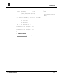
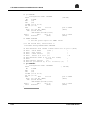
3.4.3.4
Example Sysout Report for Mono Installation - Dual Access
*** LABELs and LSS connections
Iom MSP slot 19 PX27 cab #01 rack
J21 to MSP(19)J2
* MB2-0-19-2
* * MCK1 BL-P21 *
*
* * MS K1
*
*** LABELs for other ID controllers
* MB2-1-15-P02 * * TC01
(PC0D)
* MB2-1-05-P03 * * TC10
(PC2F)
*
* * CT 11
***LAST LINE
3.5
ident K
* MS K2
* * MS K3
*
*
* * CT 12
* * MS K4
* * CT 13
Configure the Library
Refer to the documentation specific to the library concerned.
77 A7 62UP Rev00
3-17
CTS 9490 Installation and Maintenance Guide
3.6
Connect and Test the ACSLS System
3.6.1
Making the ACSLS Connection
In the ACSLS connection architecture:
• the data communication path to the LSM goes directly from the DPS 7000 Host
machine to the drives.
• the control communication path is via the ACSLS server.
There are (at least) two physical connections, both are SCSI links:
• DPS 7000 Host to drives.
• Server to Library.
Refer to the appropriate Installation Manual for full details of the library side of
the connection process.
NOTE:
Remember to check that you have turned off the power to the host DPS 7000
system before making the SCSI connections.
3.6.2
Configuring the System
The subsystem must be configured and connected to the DPS 7000 host prior to
this system configuration generation being performed. The following steps are
involved:
3.6.2.1
1.
Power on the system and subsystem.
2.
Update the CPSF.
3.
Perform the INIT IND, RESTORE, CONFIG, Stop GCOS, Reload System,
RESTORE, RESTART (COLD).
4.
Perform a MIC Remake.
Power on the System and Subsystem
Power on the subsystem.
Power on the DPS 7000 system: under SPV Graphic, select POWER ON.
3-18
77 A7 62UP Rev00
Installation
3.6.2.2
Update the CPSF
Remake the CPSF file with TSH service.
3.6.2.3
Perform the INIT IND, RESTORE, CONFIG, RESTORE, RESTART (COLD)
Step 1:
First Initialization --> SYC : IND
Step 2:
GCOS options --> RESTORE
Step 3:
GCOS configuration --> CONFIG Job
Step 4:
Shutdown GCOS --> TSYS command
Step 5:
Reload System --> SYC : RL command
Step 6:
GCOS options --> RESTORE, RESTART (COLD)
NOTE:
The first time you power on the system with the newly-attached subsystem,
initialize with IND (INIT and DIAGNOSTIC mode) to run the TEMIOM test
on the new IOM WSP. Do not use the INR.
3.6.2.4
Perform a MIC remake
See MIC User's Guide for details.
3.6.3
Performing the OLTDs
The preparation and procedures for the OLTDs are given below.
3.6.3.1
Host System
Use the STKCONF, STKCOMP tests under OLTDs (OLTD 71.46) to verify that
the SCSI control connections are all functioning correctly.
1
3
3
IMPORTANT:
Using STKCONF or STKCOMP in write mode will erase customer data.
Online help is available on the system to explain the diagnostic test.
77 A7 62UP Rev00
3-19
CTS 9490 Installation and Maintenance Guide
Prepare the drives:
Under GCOS 7, check the system can see the drives, using the command:
DC CT/LIB/36T
System response takes the format: CTxx HELD or CTXX STANDBY
(xx signifies the number of the drive)
If there are drives in the HELD state, try to turn them to STANDBY using the
command:
RDV CTxx
Verify that each drive is now in the STANDBY state using the command:
DC CTxx
If this command does not release the drives check for problems with either: the
connection, the WSP, the firmware configuration or the drive itself.
When you have resolved the problem, release each drive with the command:
RDV CTxx
Perform the OLTDs:
For each drive to be tested, issue the command:
HDV CTxx
(xx represents the number of the drive, for example 01)
Insert a cartridge tape in each drive to be tested. To do this:
• if ACSLS is NOT running, open the library and manually insert a cartridge into
each drive to test. Alternatively load the Diagnostic Cartridge using the library
test Mount to Drive x (where x is the number of the drive id to be tested).
• if ACSLS is running, under ACSSA, for each drive issue the command:
mount VOLid
0,0,2,x
(x represents the drive to test for example 0, and VOLid is the barcode of the
cartridge to insert into the drive)
1
3
3
IMPORTANT:
Using STKCONF or STKCOMP in write mode will erase customer data.
3-20
77 A7 62UP Rev00
Installation
Under GCOS 7, as the user OPERATOR, run the test(s) for each drive, using the
command:
EJ TD VL=(CTxx CONF)
Return the drives to the host:
Having completed the tests, release each drive to GCOS 7 using the command:
RDV CTxx
Verify that this has worked, and that each drive has returned to STANDBY mode
using the command:
DC CTxx
In the event of failure
See the documentation of the OLTD test and the StorageTek Diagnostics Guide.
3.6.3.2
ACSLS Connection
The test described below, verifies that ACSLS is functioning.
Preconditions for this test:
• ACSLS is installed, configured and running on UNIX server.
• CLX is installed, configured and running on DPS 7000 host.
• Drives are in STANDBY mode (if not use the command RDV CTxx to release
them)
Perform the test:
Under GCOS 7, as a user with appropriate privileges to perform a list_volume
command issue the command:
LSV VOLid:CT/LIB/36T
Verify that the cartridge is mounted correctly, even if it is unmounted again
immediately.
If the cartridge is not mounted, contact your ACSLS and CLX support people.
77 A7 62UP Rev00
3-21
CTS 9490 Installation and Maintenance Guide
❑
3-22
77 A7 62UP Rev00
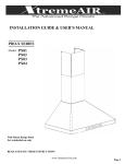
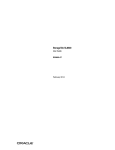
4. Maintenance
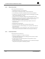
4.1
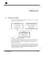
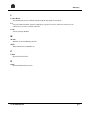
Maintenance Strategy
The maintenance strategy for the CTC D001 (CTS 9490) subsystem can be divided
into three areas as shown in Figure 4-1.
P R E D IC T IV E
P A R T N E R O R IE N T E D
N o n v isib le failu re
E rro r lo g
T h resh o ld reach ed
F ile tran sferred
C u sto m er v isib le failu re
O p erato r d u ties
A ttem p t to rep air
C all to S erv ice C en ter
PROGRAM M ED
C o m p eten ce C en ter
R em o te an alysis
C S E d isp ach ed o n site
Figure 4-1.
Maintenance Strategy
An important part of the maintenance for the CTC D001 (CTS 9490) subsystem is
based on remote capabilities. Remote Maintenance is done by B.I.I.C./STK. It
comprises running diagnostic tests remotely and monitoring actions such as
dispatch of the local CSR.
It also assumes the use of « Auto-Call » capability of the CTC D001 (CTS 9490)
Subsystem: the device(s) place a call upon detection of a MIM (Machine Initiated
Maintenance) event. These events can be triggered either locally or remotely. The
calls will be routed to B.I.I.C. STK through the Remote Maintenance Links
(cables, M.A.R.S. Box +, modem).
77 A7 62UP Rev00
4-1
CTS 9490 Installation and Maintenance Guide
4.2
Predictive Maintenance
Predictive maintenance is based on the Error Log File.
This error log file collects maximum information about errors, retries, marginal
conditions, etc. These errors are analyzed and stored by the system itself.
TeleContol and TeleAlarm are also used. For each product error, a threshold is set
and may be modified either locally or using Remote Maintenance. When an errors
occurs, a notification is sent and the System transfers the information, according to
the result of the analysis, to the appropriate Competence Center.
The Competence Center either uses Remote Maintenance to collect more
information or to start T&Ds in order to diagnose and localize the problem
remotely.
4.3
Programmed Maintenance
In many cases, as a result of the early warning given by the Error Log, the
Competence Center knows about a problem and understands its origin before the
Customer sees an error or the subsystem fails.
When an on-site intervention is necessary, the Competence Center asks the Service
Center to program the appropriate on-site assistance.
4.3.1
UNIX Server
The maintenance strategy for the CTC D001 (CTS 9490) assumes the use of part
of the remote maintenance tools provided with the system:
RSF (Remote Service Facility) which is used for AIX standard and unstructured
text error log scanning, alarm message sending and remote connecting.
4.3.2
CTC D001 (CTS 9490)
Procedures will be defined for handling error messages sent by the library or the
drives to ensure that information is passed to an Affiliate Hardware Technical
Support Remote Center or the B.I.I.C./STK. The Affiliate Hardware Technical
Support Remote Center must be ready to receive the calls coming from any system,
and depending on its analysis of the error, inform B.I.I.C./STK.
4-2
77 A7 62UP Rev00
Maintenance
4.4
Partnership Maintenance
Customer co-operation is a key factor to increase System availability.
4.4.1
Initialization of Call
In case of failure occurring without pre-alert through TeleAlarm or TeleControl, the
operator must execute the appropriate T&D and transmit results to the Service
Center at call time, in order to:
• schedule the response time to the service and determine the profile of the CSR
required
• identify the faulty FRU/ORU
• diagnose those cases where the problem is due to operation error
• initiate a remote connection for error log analysis.
4.4.2
Remote Maintenance
Remote maintenance allows you to:
• run T&Ds
• collect logging information
• collect and analyze dumps
• collect identification and technical status of the server components.
The customer must accept remote maintenance.
77 A7 62UP Rev00
4-3
CTS 9490 Installation and Maintenance Guide
4.5
Preventive Maintenance
The subsystem does not require preventive maintenance beyond normal and
periodic tape path cleaning either by the customer or automatically by the library
itself.
Tape Path Cleaning
This operation varies widely, depending on the quality of the cartridges used and
the room's environment.
The need for cleaning is determined when a « CLEAN » message appears on the
overhead display or library operator panel, or at periodic intervals such as:
• after 100 hours of operation,
• every seven days.
This operation is mainly under the responsibility of the operator or of the ACSLS
cleaning utility.
Cartridge Cleaning
Before inserting a cartridge into a transporter, inspection the cartridge for damage
or dirt. Damaged or dirty cartridges reduce the subsystem reliability. To clean
cartridges, use a lint-free cloth, or cleaning fluid Bull Express references: 6226 and
6220.
4-4
77 A7 62UP Rev00
Maintenance
4.6
Maintenance Teams
4.6.1
Organization of Maintenance Teams
E n g in eerin g
L es C lay es
E n g in eerin g
STK
S D /R & D /H D S C
D P S 70 00 T ech n ical S u p p ort
(F P E )
&
B IIC S T K
T ech n ical
C o m m itee
P ro d u ct
S p ecia lists
R em o te
S p ecialists
F ield
F ield
E n g in eers
Figure 4-2.
77 A7 62UP Rev00
Organization of Maintenance Teams
4-5
CTS 9490 Installation and Maintenance Guide
4.6.2
Remote Specialists
Remote Specialists major duties are:
• maintaining the Remote Center equipment.
• following the recommended procedures using developed tools.
• on site monitoring of the library installation team for the first installation.
• recording every site profile in the Remote Center file and keeping it up-to-date
with associated maintenance coverage.
• operating Preventive Maintenance (RMS session) and appropriate actions.
• handling the reception of library autocalls, and then performing, when required,
additional RMS connection to the CTL or to the host, in order to obtain
necessary information to complete the diagnostic.
• initializing the CSR intervention and the logistic dispatch via the local
Maintenance Base.
• performing the tests after repair.
• escalation to the Product Specialists according to defined criteria.
• answering questions for CSR and helping to solve problems which cannot be
diagnosed remotely.
• keeping accurate logs of calls and diagnostic actions. This keeps track of all
events and the associated data for the FPE, and is necessary for follow-up.
4.6.3
Product Specialists
Product Specialists major duties are:
• Bull last level support for CTC D001 (CTS 9490).
• covering the whole library subsystem, including the robot, the drives and the
whole subsystem architecture.
• providing support to the Remote Specialist to fix the problems as fast as
possible, remotely or on site.
• providing the Remote Specialist with enhanced tools to accelerate their analysis
of the part of the subsystem in which they specialize.
4-6
77 A7 62UP Rev00
Maintenance
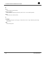
4.6.4
Intervention Scenario
C T C D 00 1
C u sto m er
M ain ten .
B ase
CSE
R espo nse
C en ter
R em o te
S pecialist
P ro du ct
S pecialist
IN C ID E N T N O T IF IC A T IO N
In cid ent rep o rt
C all
C O R R E C T IV E A C T IO N
R em ote d iag no stic
R epair & T est
D isp atch
In fo rm ation
In fo rm base & log istic
R ep ort: O K or n ot (F P E d ata)
COM PLEX PROBLEM
E scalatio n
R em ote d iag no stic o r on site assistan ce
Figure 4-3.
77 A7 62UP Rev00
Maintenance Intervention Scenario
4-7
CTS 9490 Installation and Maintenance Guide
4.7
Maintenance Tools
4.7.1
CTC D001 (CTS 9490)
See the StorageTek Diagnostics Guide.
4.7.2
DPX/20 and Estrella Maintenance Tools
The following maintenance tools are available:
• Hardware diagnostic tools - BIST, Online and Offline tests
• System diagnostic tools - debuggers, load analysis and tuning utilities, selective
dump utilities
• AIX System Trace
• Communications diagnostic tools - load analysis and tuning utilities, selective
dump utilities, trace facilities
• Remote maintenance tools through a serial modem and M.A.R.S. box
connection
• Product administration tool - SMIT (System Management and Installation Tool)
4.7.3
Other Tools
• Static protection wrist band
Part referenced with spare parts list. Must be used when repairing or testing the
CTC D001 (CTS 9490).
• Laptop computer
You need this to:
− install the microcode in the subsystem.
− configure the subsystem.
− update the Time-Of-Day clock of the subsystem.
− test the subsystem.
− display FSCs, FRUs and performance statistics of the subsystem.
− examine event and diagnostic logs of the subsystem.
− enter the maintenance device environment to maintain the subsystem.
• Auto-answer modem
Will be needed to accomplish a remote hook-up, through a serial CCITT cable
with an RJ-45 connector for the M.A.R.S. box connection. Note that CCITT
modular cable assemblies are available for connecting the adapter to the
M.A.R.S. box.
4-8
77 A7 62UP Rev00
Maintenance
4.8
Spare Parts Strategy
4.8.1
Repair Strategy
Maintenance tools will lead to the FRU/ORU being replaced.
No single component has to be replaced on a logic or analogic FRU/ORU.
All the repairable defective parts will be returned to the STK/local or distributor.
4.8.2
Spare Parts List
The global spare parts strategy takes advantage of STK's existing spare parts
logistics in accordance with the agreement between Bull and STK.
STK Present
In those countries where STK is present, STK handles spare parts (this is in order
to avoid cost duplication in both companies). Stocking, handling, and repairing of
spare parts are done by STK at no cost for Bull, but the maintenance revenue is
shared between the two companies.
STK Not Present
In those countries where STK is not present or where STK is represented by a
distributor, specific agreements have been signed between Bull and/or STK
affiliates.
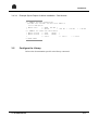
4.9
Consumables
The following parts will be available from BULL EXPRESS:
Reference
3205
3235
3260
6247-2
77 A7 62UP Rev00
Description
400 MO cartridge tape (550 feet)
500 MO cartridge tape (650 feet)
800 MO cartridge tape (1100 feet)
Cleaning cartridge
4-9
CTS 9490 Installation and Maintenance Guide
❑
4-10
77 A7 62UP Rev00
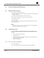
5. Reporting
5.1
Installation and Maintenance Reporting
Fill in the Installation Report according to the local procedure.
77 A7 62UP Rev00
5-1
CTS 9490 Installation and Maintenance Guide
5.2
Assessment
5.2.1
Field Performance Evaluation (FPE)
Use the Field Performance Evaluation (FPE) in the usual way:
• Specific "StorageTek Cartridge Tape Systems" (as delivered with previous 1/2"
STK libraries) 90 day Installation Report. This is to be completed at installation
time, then every 30 days whether there is a problem or not, regardless of whether
the CTC D001 (CTS 9490) was delivered with the DPS 7000 System or not.
• Intervention Report, contained in the 90 day Installation report.
These reports must be completed and sent to SD/R&D/HDSC DPS 7000 Technical
Support for analysis and recording. Two cases may occur:
• Installation Report (with or without trouble): one copy is transmitted to Quality
(Industrial Management and Angers factory) organization.
• Intervention Report: after specialist analysis, this report is systematically
transmitted to Quality (Industrial Management) and may be sent to the
concerned organization for diagnostic and/or correction purposes.
5.2.2
Quality Measurement
Quality is measured using the following metrics:
• results comparison with maintenance P&L, in terms of traveling, intervention
number, MTBF, MTTR, replaced parts number
• installation follow-up through launching group ("Groupe de Lancement")
• quantity and type of calls (Oscar)
• answering delay measure
5-2
77 A7 62UP Rev00
A. Returned Data and Messages
A.1
PRLOG Analysis
A.1.1
Channel Exceptions
At the beginning of the PRLOG there is an area called History Report for Channel
Exception, which is the log for channel exceptions that you can use to find out the
reason for the channel exception together with complementary information on the
origin of the problem.
At address 400h in this area there are 16 bytes with the following format:
LC#0 log format
B ytes 4 00 -4 01
B ytes 4 02 -4 03
:
B yte 4 04
B yte 4 05
B yte 4 06
B yte 4 07
V erstab
RFU
B yte
B yte
B yte
B yte
4 08
4 09
4 0A
4 0B
T y pe
R eason
Job N u m b er
P ro cess N u m b er
B yte
B yte
B yte
B yte
4 0C
4 0D
4 0E
4 0F
T y pe
R eason
Job N u m b er
P ro cess N u m b er
T y pe
R eason
Job N u m b er
P ro cess N u m b er
W S P -C F irm w are rev isio n level
1 st abo rted C h ann el process
2 nd abo rted C hann el process
A bo rted D riv er p ro cess
If type equals 10, it is the auto-termp.
77 A7 62UP Rev00
A-1
CTS 9490 Installation and Maintenance Guide
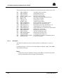
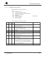
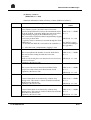
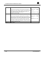
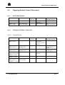
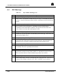
The possible Termp codes on abnormal execution of a GPOS primitive are:
01h
02h
03h
04h
05h
06h
07h
08h
09h
0Ah
0Bh
0Ch
0Dh
0Eh
0Fh
10h
11h
12h
13h
14h
15h
16h
RC_RQTM
RC_DELRQT
RC_SEPM
RC_SEPMTST
RC_SEVM
RC_NOTIFY
RC_GETDATA
RC_PUTDATA
RC_GETCMD
RC_ENDCB
RC_RESGET
RC_CRCTRL
RC_CRSERV
RC_TERMP
RC_INITSEM
RC_STARTP
RC_SETCTRL
RC_IDS
RC_SEPMT
RC_DLSERV
RC_SCTDESC
RC_GETSCT
Request timer
Delete timer
P operation
P operation test
V operation
Notify (attention)
End
Create controller
Create server
Reset flags
Start process
Automatic Detailed Status
P operation with timer
Delete server
SCT descriptors
Primitive getsct
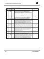
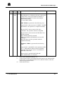
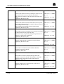
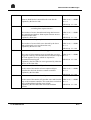
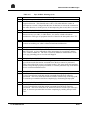
The possible Termp codes on abnormal execution detected by a channel process
are:
50h
51h
52h
53h
54h
55h
56h
57h
58h
59h
5Ah
5Bh
5Ch
5Dh
5Eh
5Fh
60h
A-2
DEV_TYPE_UNKNOWN
ERR_MES_P0_DRV
ERR_CS_TESTSEM
ERR_CS_CCE
Unknown device type
Error message from driver or P0
No longer used
Internal error, incorrect return code for CCE
processing
ERR_CS_DP_SUPSCSI
Internal dp_supscsi function error
ERR_RC_CMDSCSI
Internal cmdscsi function error
ILLEGAL_TAG
Tag message error detected
TAG_NOT_EXPECTED_HERE
Unexpected tag
ILLEGAL_TAG_IN_MS_IN_CNL Tag error detected
ILLEGAL_CCE_CODE
Illegal CCE from P0 received.
ILLEGAL_CMD_SCSI_ASKED Internal error, unexpected SCSI command
ILLEGAL_MSG_SCSI_ASKED
Internal error, unexpected SCSI message
ILLEGAL_SCSI_REQUEST
No longer used
SCSI_COMMAND_ERROR
No longer used
TIMER_START_SUP_EXPECTED
TIMER_DELAY_SUP_EXPECTED
TIMERQUEUE_EXPECTED
77 A7 62UP Rev00
Returned Data and Messages
61h
62h
63h
64h
65h
66h
67h
68h
69h
6Ah
TIMERBUSY_EXPECTED
ILLEGAL_PAGE_SELECTED
ERR_DRIVER_UNKNOWN
RC_GPOS_UNKNOWN
SENDER_UNKNOWN
SENDER_NOT_EXPECTED
SRC_SID_UNKNOWN
SRC_SID_NOT_EXPECTED
ILLEGAL_DEVICE_STATUS
SENSE_CODE_UNKNOWN
6Bh
6Ch
6Dh
6Eh
ILLEGAL_SENSE_KEY
ILLEGAL_ERROR_CODE
ILLEGAL_ERROR_CLASS
SCSI_PARAMETERS_ERROR
6Fh
70h
71h
72h
73h
74h
75h
76h
77h
78h
79h
ILLEGAL_P0_REQUEST
ILLEGAL_P0_REQUEST_TYPE
ERR_STATEDEV
TERMP_DRIVER
DELETE_SERVER
NO_REVISION_LEVEL
ILLEGAL_ID_TAPE_POSITION
ILLEGAL_PARTITION_ID
QUEUEP0_OVERFLOW
ILLEGAL_ASC
ILLEGAL_ASCQ
7Ah
7Bh
7Ch
7Dh
7Eh
ILLEGAL_SVID
TIMEOUT_ABORT
ILLEGAL_COM_NB
ERROR_ABORT
UNEXPECTED_ DRIVER_ERR
77 A7 62UP Rev00
Internal error, select page mode is unexpected
Unexpected driver error
Unknown or unexpected GPOS return code
Message from unknown sender
Unexpected message from this sender
Unknown source ID
Unexpected source ID
Unexpected status
Incorrect or unknown additional sense code
(SCSI)
Undefined sense key (SCSI)
Undefined sense code (SCSI)
No longer used
Internal error, incorrect parameter in SCSI
command
Driver performed termp
Abnormal delete server processing
WSP revision is 00 (00 = illegal)
Illegal partition ID received
Illegal or unknown additional sense code
Illegal or unknown additional sense code
qualifier
Illegal server ID
Timeout on abort message request
Driver error: incorrect command number
Incorrect abort SCSI command
A-3
CTS 9490 Installation and Maintenance Guide
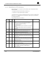
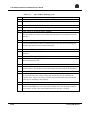
The possible Termp codes on abnormal execution detected by a driver process are:
20h
21h
22h
23h
24h
25h
26h
27h
28h
29h
2Ah
2Bh
2Ch
2Dh
2Eh
2Fh
30h
31h
32h
33h
A.1.2
ERR_PIOPROC
ERR_INMESS
ERR_VALTAG
QUEUE_MESS_FULL
PROC_OVF
DRIV_OVF
VRAM_OVF
SCRIPT_OVF
ERR_SCHEDULE
ERR_SCRIPTLCA
ERR_DATALCA
ERR_VRAMLCA
ERR_DIFFSENS
ERR_UNKNOWN
ERR_MESSLEN
ERR_CONFIG
ERR_MESSIDENT
ERR_MESSREF
UNEXPECTED_ITNCR
ITNCR_LOOP
Abnormal value in pioproc
Unidentified message
Unknown message type
Message queue overflow
Too many executing channel processes
Driver table overflow
VRAM data overflow
VRAM script overflow
Incorrect number of scheduler entries
Script parity error detected by CA
Data buffer parity error detected by LCA
VRAM parity error detected by LCA
Single-ended device connected to the SCSI bus
Unknown LCA interrupt
Outgoing message too long
Transfer configuration error
Identification message error
Configuration message error
Current NCR IT with no command on device
Loop in IT sequence
I/O Errors
The PRLOG contains an area for each logical device called History report for
CTxx.
It contains all types of I/O error (NT with marginal condition, ASR, ANR, AMR)
and Attention messages.
NOTE:
Certain I/O errors and Attention messages from WSP-C are filtered by GCOS
(AVAIL and PIARS) and do not appear in the PRLOG.
A-4
77 A7 62UP Rev00
Returned Data and Messages
A.1.2.1
PSB/DSB Termination Reports
PSB and DSB terminations are listed below.
PSB1
bit 0
bit 1
bit 2
bit 3
bit 4
bit 5
bit 6
bit 7
Modifier Always 1
Status Control (origin of status)
Channel Program Check (programming error)
Detailed Status Pending
Data Error
Hardware Condition
Operational Check
Device Condition
Hardware fault
PSB2 in Termination is defined as follows:
PSB2 EVEN PSB1
Error description
Remarks
(bit) T Type (bit)
0
ASR 0,1,4 CHANNEL parity error
A parity error has been detected in data transmission
on the channel interface.
Detail in DSB3
1
ASR 0,4
Tape positioning error
(1) LOCATE BLOCK has failed
(2) An error in the block ID sequence has been
detected.
2
Zero (RFU)
3
zero (RFU)
4
ASR 0,4
ID burst error
Writing of the ID mark on BOT was unsuccessful
(read after write error)
5
ASR 0,4
READ/WRITE error
DSB7 bits 4 and 5
An error has been detected during the read check after
a write operation
6
ASR 0,6
Path switch request
The CTC requests that access to the device be made
through the other CTC in dual LOS configuration:
- because there is data in the buffer of the other CTC,
or
- for better load distribution.
7
Zero (RFU)
77 A7 62UP Rev00
A-5
CTS 9490 Installation and Maintenance Guide
PSB3 is defined as follows:
PSB3 EVEN PSB1
Error description
(bit) T Type (bit)
0
NT 0,1,6 Unequal length check
ASR
The length of the data field read on the media is
different from the CCE count, or discrepancy between
specified length of control command and CCE count.
NOTE: This bit is not set to one when a Tape Mark is
encountered during a Read command.
1
ASR 0,6
Reserved
The drive is seized by another path (caused by explicit
seize, implicit seize, status pending, or diagnostic
ANR 0,5,6 mode), or has been unlocked from another path.
2
AMR 0,5
Off-line
The subsystem could not execute the channel program
because the device was in the off-line state or the
subsystem could not complete the command because
the device entered the off-line state.
3
AMR 0,6
Write protect
ASR
The subsystem could not execute a write operation
because the cartridge or the drive was write protected
either manually (AMR) or by Function mask (ASR).
4
AMR 0,5
Standby
The subsystem could not execute (or complete) the
channel program because the device was in (or
entered) the standby state.
5
ASR 0,5
Tape time out
No block was detected in reading after x meters of
tape movement. "x" is subsystem specific.
6
NT 0,7
End of file
ASR
A tape mark was detected during a READ or SPACE
command. If the command was not a SPACE TO TM
command, ASR is generated. If the command was a
SPACE TO TM, a normal termination is generated.
A-6
Remarks
77 A7 62UP Rev00
Returned Data and Messages
PSB3 EVEN PSB1
Error description
(bit) T Type (bit)
7
NT 0,7
EOT/BOT
ASR
This indication is set whenever the tape is positioned:
- in the EOT** zone [zone defined as starting at
beginning of logical EOT marker and ending at
physical end of tape],
- or on the BOT marker.
Remarks
ABN. TERM. is generated in the following cases:
Logical EOT** and execution of a WRITE*, WRITE
TM, ERASE. The operation is completed normally.
Physical EOT** and execution of the same
commands. The operation cannot be completed.
Physical EOT** and execution of FWD SPACE or
READ command.
BOT and BCK SPACE command.
EOD*** and READ, FWD SPACE or LOCATE
command.
In the last three cases the operation cannot be
completed normally.
NORMAL TERM. is generated in the following
cases:
Logical EOT** and WRITE with command modifier
bit = 1, FWD SPACE, READ, and all commands
involving backward tape motion: BACKSPACE,
REWIND, UNLOAD.
Physical EOT** and SECURITY ERASE
BOT and REWIND, or UNLOAD.
*
**
***
77 A7 62UP Rev00
Write with command modifier bit = 0.
Using 36 tracks tapes Logical (Physical) EOT status is sent when the R/W
head reaches Logical (Physical) EOV. EOV (End Of Volume) is then the
functional equivalent of EOT.
EOD (End Of Data).
A-7
CTS 9490 Installation and Maintenance Guide
A.1.2.2
Detailed Status for All TCA Sub-Systems
The detailed status is an extension of the summary status. Transmission of these
statuses is made:
• through the automatic detailed status mechanism, or
• in response to a Store detailed status command.
A maximum count of 128 bytes of detailed status may be sent by a Cartridge Tape
Subsystem. TCA standard bytes are described here, other bytes are considered as
TCA subsystem specific.
The standardized bytes are as follows :
DSB0 EVEN PSB1
Error description
(bit)
T
bit
Type
0
ASR 0,1,2 Illegal command
This bit is set to one on the following conditions :
- Command with illegal encoding
- Invalid flag field
- Command valid only for a controller was issued to a
device
- Command valid only for a device was issued to a
controller
1
ASR 0,1,2 Illegal argument
An illegal count has been detected by the CTC
2
ASR 0,1,2 Illegal data
An illegal data was detected by the CTC
3
ASR 0,1,2 Illegal sequence
An illegal CCE sequence was detected by the CTC
4
ASR 0,1,2 Resume error
RESUME command (IOC instruction) has been issued
to an active LC
5
ASR 0,1,2 Function mask reject
A function not existing in the details of the subsystem
has been specified or an invalid combination of bits in
DSB3 has been sent
6
ASR 0,1,2 Function mask violation
A command requiring an operation not allowed by the
function mask was issued
7
ASR 0,1,2 Programmed release
The termination of the channel program was caused
by an ABORT command or a DISCONNECT
(IOC instruction)
A-8
Remarks
77 A7 62UP Rev00
Returned Data and Messages
DSB1 EVEN PSB1
Error description
(bit)
T
bit
Type
0
Zero (RFU)
1
ANR 0,5
Device fault
A fault was detected in the device
2
ANR 0,5
Overrun
Data overrun/underrun occurred during data
transmission
3
Zero (RFU)
4
ANR 0,5
Cartridge fault
Non standard cartridge or loosely wound tape
5
ANR 0,5
Retry failure
A second error in the retry process resulted in an
unrecoverable state
6
Zero (RFU)
7
Zero (RFU)
Remarks
DSB2 EVEN
(bit)
T
Type
0
ASR
1
ANR
2
3
ASR
Remarks
PSB1
bit
0,6
0,5
0,5
4
5
6
ASR
0,6
7
ANR
0,5
77 A7 62UP Rev00
Error description
Accessor parameter error
Cell fault
Zero (RFU)
Buffer empty
No data block remains in the CTC buffer when a
READ BUFFER command is received (in this case
the CTC transfers one byte of non significant data)
Zero (RFU)
Zero (RFU)
Buffer busy
No buffer segment is available because they are all
allocated to other drives and contain data
Controller fault
A fault or a time out has been detected in some part of
the CTC
Currently NA
Currently NA
See details in
DSB3
A-9
CTS 9490 Installation and Maintenance Guide
A.1.2.3
CTC D001 (CTS 9490) Specific DSBs
DSB3
00
01-5F
82
91
D3
BC
Cx
C1
C2
C4
C5
C8
FF
DSB4
A-10
Description
No error
SCSI ERPA code (4220/4280)
Channel hardware time out
Formatter time out
Device busy
Lost position
Function mask error :
- Illegal parameter in function mask
- Illegal combination in function mask
- Illegal tape position
- Request not allowed in standby
- Write protect by function mask
4890/9490 : Formatter or device error
Last CCE received
DSB5 bit #
0
1
2
3
4
5
6
7
Description
Successful HW error retry
Successful data error retry
Successful sequence error retry
Successful device error retry
History counter overflow
Error corrected in data buffer
History counter read request
Unlock executed
DSB6 bit #
0
1
2
3
4
5
6
7
Description
Illegal block size
Positioning command request
Incompatible format
Zero
Read density ID failed
Incompatible cartridge
Zero
Invalid block ID
77 A7 62UP Rev00
Returned Data and Messages
DSB7 bit #
0
1
2
3
4
5
6
7
DSB8
DSB9 bit #
0
1
3
4
5
6
7
Description
Tape synchronous mode
Zero
Error (same) path retry request
Compacted data in buffer
Deferred check event
Buffered data (= 0 for 4220/4280)
zero
Alternate drive retry request
Zero
Description
Block Id valid (=0 for 4220/4280)³³
No repositioning needed
Zero
BOT
Physical EOT
End of Data mark
Zero
DSB10 bit #
Description
0
Formatter status valid
1-3
DSB's>3 format
- 000 : controller/formatter/drive status
- 010 : history counter status
4-7
DSB11-14
DSB15-18
DSB19
DSB20-21
DSB22
77 A7 62UP Rev00
Remarks
0x84: DSB>32 =
formater status
0xA4: DSB>32 =
history counter
status
Controller type = 0100
First block Id
Second block Id
= zero if no data in the buffer not zero otherwise
Firmware revision level
Product Identification ( Same as DSB91)
A-11
CTS 9490 Installation and Maintenance Guide
DSB23 bit #
0
1
2
3
4-7
Zero
IDRC capability feature
zero
SCL autoloader installed
Zero
DSB24-31
bit 0-6
bit 7
zero
write protect switch is set
DSB3-127
Description
Description
Description
If DSB10 bits 1-3 = 000 :
Controller / formatter / drive status
If DSB10 bits 1-3 = 010:
History counter status
A-12
77 A7 62UP Rev00
Returned Data and Messages
(i) Controller / Formatter / Drive Status
(DSB10 bits 1-3 = 000)
DSB32 bit#
0-3
4
5
6
7
Zero
Tape mark detected
BOT
EOT
Write protected cartridge
Description
DSB33 bit#
0
1-7
Description
=1 if SCSI sense bytes are valid
NFS
DSB #
DSB34-59
Description
Device SCSI sense bytes 2-N:
Remarks
- N=27 for 4220/4280
- N=21 for 4890
DSB60-71
DSB72-75
DSB76-89
DSB90
77 A7 62UP Rev00
(
(
(
See Request
sense DATA in
this Appendix
- N=17 for 9490
Last failed SCSI command
Device sense bytes 28-31 (Physical block ID)
for 4220/4280
Reserved (zero)
Vendor identification (STK = 8216)
DSB91
Product identification
4890 = 9116, 9490 = 9216
DSB #
DSB92-95
DSB96-107
DSB108
DSB109
DSB110
DSB111
DSB112-115
Description
Product revision level (as returned by device)
Current SCSI command
Device status
Driver status
Last message in on SCSI
Last message out on SCSI
Last event on SCSI
A-13
CTS 9490 Installation and Maintenance Guide
DSB #
DSB116
DSB117
DSB118
DSB119
DSB120
Description
GPOS return code if primitive is unsuccessfully executed
Microcode procedure in terminate process code
Order code in procedure of terminate process
GPOS return code if IDS primitive is unsuccessfully executed
GPOS return code if ENDCB primitive is unsuccessfully
executed
DSB121-126 Reserved (zero)
End command block (GPOS primitive) processing error
DSB127
A-14
77 A7 62UP Rev00
Returned Data and Messages
(ii) History Counters
(DSB10 bits 1-3 = 010)
Statistical information content of history counters (DSB34 to DSB127)
DSB
Description
DSB33
This byte is set to a non-zero value if one or several track
error counters exceed a specified value. Execute the
specific T&D TWPLOG to retrieve the information stored
in the SCSI WSP_Controller. DSB33 prevents reset of this
complementary logging by Read Buffered Log CCE.
The event will be reported (without complementary logging
reset) once per hour until:
- a specific Native Command is executed through the T&D:
TWPLOG (*)
- or until the next REPCH is executed on the controller (*)
Remarks/related
status
Event= NT
PSB1 bit 0, 5 =1 DSB5
bit 6 = 1
DSB10 bits 1-3 = 010
(See DATA Logging
format and meaning in
this Appendix)
DSB34-37
(*) : After this event, complementary logging is reset
Read Forward Data Checks
PSB1 bit 0, 5 =1 DSB5
bit 6 = 1
DSB38-41
This count indicates the number of records which had a
data check while reading forward, that were later
recovered.
Each record can only have one data check even if recovery
took several retries.
Updated by the Device Side.
Write Forward Data Checks
This count is the same as Read Forward Data Checks
except for records which are written instead of read.
Updated by the Device Side.
PSB1 bit 0, 5 =1 DSB5
bit 6 = 1
DSB42-45
DSB46-49
Read Data Checks without Hardware Indicators
Event= NT
DSB10 bits 1-3 = 010
Event= NT
DSB10 bits 1-3 = 010
Event= NT
Count of data check errors detected by software only
during reads. This count is a subset of Read Forward and
Read Reverse data checks.
Updated by the Device Side.
Write Data Checks without Hardware Indicators
PSB1 bit 0, 5 =1 DSB5
bit 6 = 1
Count of data check errors detected by software only
during writes. This count is a subset of Write Forward and
Write Reverse data checks.
Updated by the Device Side.
PSB1 bit 0, 5 =1 DSB5
bit 6 = 1
77 A7 62UP Rev00
DSB10 bits 1-3 = 010
Event= NT
DSB10 bits 1-3 = 010
A-15
CTS 9490 Installation and Maintenance Guide
DSB50-53
Read Recovery Retry Count
Event= NT
PSB1 bit 0, 5 =1 DSB5
bit 6 = 1
DSB54-57
Count of the number of times an attempt to read a record
was retried before recovery failed or succeeded.
This count only applies to the last block read with a data
check.
Updated by the Device Side.
Write Recovery Retry Count
PSB1 bit 0, 5 =1 DSB5
bit 6 = 1
DSB58-61
Count of the number of blocks which have to have prefix
erase written before the block in order for the record to be
successfully written to tape.
This count does not contain the erase gaps written.
Updated by the Device Side.
Read Transient Conditions
PSB1 bit 0, 5 =1 DSB5
bit 6 = 1
DSB62-65
The number of times read blocks were retried but resulted
in unsuccessful recovery after one retry.
The first recovery step usually changes no parameters in
order to see if the error is transient.
Updated by the Device Side.
Write Transient Conditions
Same as Read transient Conditions except for Writes.
Updated by the Device Side.
PSB1 bit 0, 5 =1 DSB5
bit 6 = 1
DSB66-69
Buffer Read Blocks Corrected
The number of read blocks in the buffer which the
hardware corrected on the fly.
Updated by Host Side.
DSB70-73
DSB74-77
Device Read Blocks Corrected
DSB10 bits 1-3 = 010
Event= NT
DSB10 bits 1-3 = 010
Event= NT
DSB10 bits 1-3 = 010
Event= NT
DSB10 bits 1-3 = 010
Event= NT
PSB1 bit 0, 5 =1 DSB5
bit 6 = 1
DSB10 bits 1-3 = 010
Event= NT
The number of blocks read from the tape which the
hardware corrected on the fly. This includes corrections
from tape and corrections from the buffer memory.
Updated by Host Side.
Buffer Write Blocks Corrected
PSB1 bit 0, 5 =1 DSB5
bit 6 = 1
Same as Read blocks Corrected but for write blocks.
Updated by the Device Side.
PSB1 bit 0, 5 =1 DSB5
bit 6 = 1
DSB10 bits 1-3 = 010
Event= NT
DSB10 bits 1-3 = 010
A-16
77 A7 62UP Rev00
Returned Data and Messages
DSB78-81
Device Write Blocks Corrected
Same as Read blocks Corrected but for write blocks.
Updated by the Device Side.
DSB82-85
DSB86-89
Data Transfer Errors
- excluding data request timeouts -
Event= NT
PSB1 bit 0, 5 =1 DSB5
bit 6 = 1
DSB10 bits 1-3 = 010
Event= NT
The number of errors detected transferring data between
the controller and the host. Data request timeouts are not
included in this count.
Updated by Host Side.
Temporary Driver errors
PSB1 bit 0, 5 =1 DSB5
bit 6 = 1
The number of errors which were detected by the Servo
and subsequently recovered from after retry.
Updated by the Device Side.
PSB1 bit 0, 5 =1 DSB5
bit 6 = 1
DSB90-93
Permanent Errors Logged
DSB94-101
The count of all permanent errors reported that were also
logged in event log. Note that this does not include requests
for read opposite recovery, which are reported as
permanent but not logged.
Updated by the Host Side for errors generated by either the
Device or the Host Side.
Channel Read Bytes Processed
64-bit count of the number of non-compressed bytes
transferred to the host from the common controller.
Updated by the Host Side.
DSB102-109
Device Read Bytes
DSB10 bits 1-3 = 010
Event= NT
DSB10 bits 1-3 = 010
Event= NT
PSB1 bit 0, 5 =1 DSB5
bit 6 = 1
DSB10 bits 1-3 = 010
Event= NT
PSB1 bit 0, 5 =1 DSB5
bit 6 = 1
DSB10 bits 1-3 = 010
Event= NT
64-bit count of the number of bytes that were read from the PSB1 bit 0, 5 =1 DSB5
tape to the common controller. This count does not include bit 6 = 1
any read ahead data including super blocks.
DSB10 bits 1-3 = 010
Updated by the Host Side after successful read data
transfer.
77 A7 62UP Rev00
A-17
CTS 9490 Installation and Maintenance Guide
DSB110-117
Channel Write Bytes Processed
64-bit count of the number of bytes that were transferred
from the host to the common controller. This represents the
non-compressed bytes. This count is updated after every
successful write transfer from the host.
Updated by the Host Side.
DSB118-125
Device Write Bytes Processed
Event= NT
PSB1 bit 0, 5 =1 DSB5
bit 6 = 1
DSB10 bits 1-3 = 010
Event= NT
PSB1 bit 0, 5 =1 DSB5
64 bit count of the number of bytes that were written to
tape from the common controller. This count represents the bit 6 = 1
compressed bytes. This count is updated after a successful
DSB10 bits 1-3 = 010
write from the host to the common controller. If the data
could not be written to tape, then the counts will be off by
the amount of data buffered within the common controller.
Updated by the Device Side.
DSB126-127 Zero (RFU)
A-18
77 A7 62UP Rev00
Returned Data and Messages
A.2
Triggering Remote Control (Telecontrol)
A.2.1
All TCA Sub-Systems
Event
Information
PSB2/bit 0
Channel parity error
PSB2/bit 1 &
DSB3 = 0xBC
Tape positioning
error. Lost position
Severity
Level
***
***
A.2.2
CTC D001 (CTS 9490 - TimberLine)
A.2.2.1
Formatter Errors
Event
Information
Severity
Level
***
PSB2/bit 1 &
DSB3 = 0x91
Formater time-out
DSB10=84 &
DSB35 bit4-7=3
Device Fault:
Medium Error
***
DSB10=84 &
DSB35 bit4-7=4
DSB10=84 &
DSB35 bit4-7=B &
DSB45:2 = 4700
DSB10=84 &
DSB45:2 = 3300
DSB10=84 &
DSB35 bit4-7 = 7
& DSB45:2 = 3000
Device Fault:
Hardware error
Aborted command
***
Tape length error
*
Write attempt to 18track cartridge
*
77 A7 62UP Rev00
***
Probable Cause
SCSI cables or
connector
Media defective
Probable Cause
Intervention
Required ASAP
Yes
No
Change the media.
Intervention
Required ASAP
Yes
If not transient:
SCSI cable,
connector, or device
interface
Media defective
Yes, if fault persists
after change of
media
Device fault
Yes, if several errors
of same type
SCSI cable or
Yes
connector
Wrong cartridge
type
No
No
A-19
CTS 9490 Installation and Maintenance Guide
A.2.2.2
Statistics
Event
DSB10=A4
Information
Statistics Threshold
exceeded
Statistics Threshold
DSB10=A4 and
DSB33 not equal to exceeded beyond
counter n° 21
00
Severity
Level
***
***
Probable Cause
Media or cartridge
device problem
Media or cartridge
device problem
Intervention
Required ASAP
Yes
Look at the statistics
Yes
Run the OLTD
TWPLOG
Counter threshold = 25 events read for MB (except PC30 for which the threshold is
50 events). For counters counters >21 , see Log Sense Results in this appendix.
A-20
77 A7 62UP Rev00
Returned Data and Messages
A.3
Request Sense Results
Table A-1 shows the data returned for a sense request.
Table A-1.
Byte 0
Byte 1
Byte 2
Byte 3
Byte 4
Byte 5
Byte 6
Byte 7
Byte 8
Byte 9
Byte 10
Byte 11
Byte 12
Byte 13
Byte 14
Byte 15
Byte 16
Byte 17
Byte 18
Byte 19
Byte 20
Byte 21
Bit 7
Valid
0
FM
msb
Sense Request Data Returned
Bit 6
Bit 5
Bit 4
0
EOM
0
ILI
0
0
Bit 3
Error Code
0
Bit 2
Bit 1
0
0
Sense Key
Bit 0
0
Information Bytes
lsb
0
0
0
0
0
0
0
0
0
0
0
0
msb
0
0
0
0
Additional Sense Length (= 0Eh)
0
0
0
0
0
0
0
0
0
0
0
0
0
0
0
0
Additional Sense Code
Additional Sense Code Qualifier
0
0
0
0
0
0
0
0
0
0
0
0
0
0
0
0
Fault Symptom Code
0
0
0
0
0
0
0
0
0
0
0
0
0
0
0
0
lsb
0
77 A7 62UP Rev00
0
CCTU Detailed Status Code
0
CLND
CLN
0
0
0
A-21
CTS 9490 Installation and Maintenance Guide
Explanation of Bytes
Byte 0
The VALID bit when set indicates that bytes 3, 4, 5 & 6 contain valid information
(see below).
The Error Code bits are used to indicate whether the CHECK CONDITION and
Sense Data apply to the command that returned the CHECK CONDITION (error
code set to 70h) or to a previous command, such as a buffered WRITE, which had
already returned GOOD status (deferred error, error code 71h).
Byte 1
This byte is always set to zero.
Byte 2
The Filemark (FM) bit indicates that the LUN encountered a filemark when
executing the last command. This may or may not be the cause of the CHECK
CONDITION status.
The End of Medium (EOM) bit indicates that tape is in one of the 3 positions
shown in Table A-2. Again this bit may or may not be the cause of the error.
Table A-2.
Request Sense EOM Positions
Additional Sense Code
Beginning of medium
Early warning
End of medium
00
00
00
Additional Sense Code
Qualifier
04
00
02
The Illegal Length (ILI) bit indicates that the size of the block read from tape did
not match the length specified in the CDB.
A-22
77 A7 62UP Rev00
Returned Data and Messages
The SENSE KEY bits are as defined in Table A-3.
Table A-3.
Code
0h
1h
2h
3h
4h
5h
6h
7h
8h
9h
Ah
Bh
Ch
Dh
Eh
Fh
77 A7 62UP Rev00
Sense Key Codes
Meaning
No Sense Data available. CHECK CONDITION likely to have been caused
by FM, EOM or ILI being set.
Not supported.
Not Ready. Addressed LUN is not ready to execute tape related commands.
Medium Error. Non-recoverable tape error was encountered.
Hardware Error:
a. Parity error on SCSI bus, and retry capability exhausted,
b. RAM error detected during power-on self-test,
c. Hardware error detected during LUN diagnostic checks, or while
performing the command.
Illegal Request: indicates an illegal parameter in the CDB (e.g. an
unsupported command), or in the additional parameters supplied as data; can
also indicate an illegal Identify message.
Unit Attention. This status is set to indicate that the LUN's cartridge may
have been removed or exchanged, or the CTU reset since the last command
was given. When set, the current command is effectively aborted (except
INQUIRY) and no further action taken. All subsequent commands are then
implemented as normal. Note that all INITIATORs will be informed in turn
if and when they attempt to address the LUN for which the condition was
detected.
The CTU sets the ATTENTION status in response to:
a. power-on,
b. BUS DE\/ICE RESET message,
c. RESET on SCSI bus,
d. unit has been detected off-line at some time since last command issued.
File Protected. Set if any WRITE/ERASE command is requested to a write
protected cartridge.
Blank Tape. The logical end of media has been detected, or a previously
unused or unrecognized tape has been loaded.
Reserved.
Reserved.
Aborted Command. Indicates that the TARGET has aborted the command.
Reserved.
Volume Overflow. Indicates that the last command has left data in the buffer
which hasn't been written to tape. The data can be retrieved by the
RECOVER BUFFERED DATA command.
Reserved.
Reserved.
A-23
CTS 9490 Installation and Maintenance Guide
Bytes 3, 4, 5, 6
The Information Bytes are used to indicate any difference (residue) between the
requested length (bytes or blocks) and the actual length in any given command.
The CTU supports negative residues which are represented in twos-complement
notation (see SPACE command).
Byte 7
The ADDITIONAL SENSE LENGTH byte indicates the amount of additional
Sense Data available. This is always set to 14.
Bytes 8, 9, 10, 11
These bytes are always set to zero.
Bytes 12, 13
The Additional Sense Code and Additional Sense Code Qualifier bytes will often
contain further information related to the error or exception condition that has
occurred. The codes supported are shown in Table A-4.
A-24
77 A7 62UP Rev00
Returned Data and Messages
Table A-4.
ASC and ASCQ of Request Sense(1/2)
Sense
Key
0
ASC
ASCQ
00
00
00
00
33
40
00
01
02
04
00
00
No additional sense data
Filemark detected
Logical end of tape detected
Beginning of medium detected
Tape length error, non-standard cartridge
Diagnostic failure
2
04
04
04
3A
00
01
03
00
LUN not ready, cause unknown
Drive Not Ready, coming Ready
LUN not ready, manual intervention required
LUN not ready, no cartridge present
3
00
00
11
14
31
50
51
00
00
44
4B
53
53
40
01
04
00
00
00
02
00
00
00
00
01
00
Permanent error on a write (write data may be trapped in the
buffer)
Permanent error on a read
Invalid or out-of-sequence block ID
Format corrupted
Write append error
Erase failure
End of medium detected
No additional sense data
Target failure, general hardware error
SCSI bus Data phase error detected
Media load or eject failed
Unload error
Diagnostic failure
4
77 A7 62UP Rev00
Meaning
A-25
CTS 9490 Installation and Maintenance Guide
Table A-4.
4. ASC and ASCQ of Request Sense (2/2)
Sense
Key
5
ASC
ASCQ
Meaning
00
20
24
25
26
3B
3B
3D
00
00
00
00
00
0E
0D
00
No additional sense data
Invalid operation code in command from host
Invalid field in CDB
logical unit not supported
Invalid field in parameter list
Source empty
Destination full
Error in Identify message
6
28
29
00
00
Transition from Ready-to Not Ready
Power-on reset occurred
7
27
30
00
00
Write operation to file-protected tape
Write inhibited, incompatible medium
8
00
00
30
00
05
01
Media void encountered (blank tape)
End-of-data detected
Unknown format
B
08
15
43
45
47
48
49
3D
00
02
00
00
00
00
00
00
Internal LUN communication failure
Position error
Error detected during Message phase
Select or Reselect failure
SCSI bus parity error
Initiator-detected error message received
invalid message error
Invalid field in Identify message
D
00
02
End-of-medium detected
Byte 14
Not supported.
Bytes 15, 16, 17
Always set to zero.
A-26
77 A7 62UP Rev00
Returned Data and Messages
Byte18, 19
These are vendor unique fault symptom codes that help to define the fundamental
cause of the CHECK CONDITION where appropriate.
Byte 20
This is the internal fault code from which the Sense Key and qualifiers have been
derived. They are detailed in Table A.5.
Byte 21
Bit
Meaning
7,6,5
Not used.
4
CLND. Set to 1 when the CTU has been cleaned.
Reset to 0 on receipt of the next REQUEST SENSE
command.
3
CLN. Set to a 1 when it is time to clean the CTU.
Reset to 0 when a successful cleaning cycle has been
performed.
2,1,0
Not used.
77 A7 62UP Rev00
A-27
CTS 9490 Installation and Maintenance Guide
A.4
DSC Meanings
Table A-5.
DSC
01
A-28
Byte 20 DSC Meanings (1/4)
Meaning
DSC_WRITE_ID_MARK_CHECK
The ID Burst could not be written to tape successfully. The error is probably
media related. The ID Burst includes the zeros on wrap 2, the Density ID pattern
on wrap 1, and the ID Separator pattern which is immediately after the Density ID
pattern.
02
DSC_PEOT_OR_PEOV_ENCOUNTERED
A motion command in the forward direction encountered PEOT on an 18 track
drive, or PEOV on a 36-track drive. Excluded from the forward motion
commands is DATA SECURITY ERASE. The tape has run out of room for a
write, or there is no more data on the tape for a read.
03
DSC_WRITE_DATA_CHECK
The error was a data check (media related) during a write operation. The error
could be on a record, tape mark, reversal mark, or host erase gap. This code is not
reported for ID Burst errors.
04
DSC_END_DATA_RECORD_SEEN
An end data record was read from tape. This always means that the data on the
logical EOT side of the mark is from a previous write pass, and is therefore not
guaranteed to be in sequence with the records before the end data record.
05
DSC_READ_DATA_CHECK
The record, tape mark, end data mark, or reversal mark could not be read
successfully. The error is probably media related.
06
DSC_TAPE_LENGTH_ERROR
The Servo detected that the tape is too short, and the Servo cannot reliably
generate the positions on tape (LEOV, PEOT etc.) that the host expects it to do.
This error means the Servo detected that the tape radius was too short.
07
DSC_TAPE_VOID
The tape appears to be erased or never recorded in this area. The error is probably
media related, unless someone is holding the tape off the tape head. This error is
not given if the ID Burst cannot be read. NOT_CAPABLE is given instead.
77 A7 62UP Rev00
Returned Data and Messages
Table A-5.
Byte 20 DSC Meanings (2/4)
DSC
08
Meaning
DSC_READ_OPPOSITE_RECOVERY
The data cannot be read in the direction originally asked for, but can be read in the
opposite direction. This detailed status code is sent when the time it takes to
uncompress a record is longer than the time for the host to reissue the command in
the other direction, or in the process of uncompressing the record, there is an error.
09
DSC_PATH_EQUIPMENT_CHECK
The hardware in the CTU (excluding Servo) has reported an error, or the code
detects an error (via CRC, or LRC checks, etc.) that is related to hardware
malfunction. This type of equipment check is related to the data path in the CTU.
0A
DSC_DRIVE_EQUIPMENT_CHECK
The hardware in the CTU Servo has reported an error, or the code detects an error
(sensor not working, etc.) that is related to hardware malfunction.
0B
DSC_PERMANENT_EQUIPMENT_CHECK
This means the hardware in the CTU has detected an error with the operation of
the CTU itself. A piece of hardware (like an interrupt) is not working, and the
CTU cannot continue on. The error is caused by hardware malfunction or some
wise guy grounding pins to see what will happen.
0C
DSC_TAPE_LOST_TENSION
The hardware in the CTU Servo has dropped tape tension. The tension is out of
specification such that motion commands from the host cannot be performed.
This is also referred to as tape is no longer loaded. This error means the hardware
failed to keep the tape properly tensioned, or someone pulled the tape such that the
Servo could not maintain tension.
0D
DSC_TAPE_LOAD_FAILURE
The hardware in the CTU Servo was unable to load the tape properly. The tension
is out of specification such that motion commands from the host cannot be
performed. This error means the hardware failed to load the tape in the tape path,
or someone prevented the load from completing by obstructing the tape path.
0E
DSC_CSL_TAPE_LOAD_FAILURE
The hardware in the CTU CSL was unable to load the tape properly. The tension
is out of specification such that motion commands from the host cannot be
performed. This error means the CSL hardware failed to load the tape in the tape
path, or someone prevented the load from completing by holding the tape in the
CSL.
77 A7 62UP Rev00
A-29
CTS 9490 Installation and Maintenance Guide
Table A-5.
A-30
Byte 20 DSC Meanings (3/4)
DSC
0F
Meaning
DSC_DATA_SECURITY_ERASE_FAILURE
This means the error was during a DATA SECURITY ERASE command.
10
DSC_COMMAND_REJECT
This means the command has invalid parameters, or is out of context.
11
DSC_BLOCK_ID_SEQUENCE_ERROR
A block was read that was out of sequence: its block ID was not in sequence from
the last block read. The user has read beyond the point were good data exists on
the tape.
12
DSC_ILLEGAL_DATA_FORMAT
An illegal sequence of data records, or an illegal data value has been seen. The
error is possibly media related, (an intervening record may have been dropped),
but the tape may have been written incorrectly.
13
DSC_BACKWARD_AT_BOT
A READ REVERSE was requested while the drive was positioned at beginning of
the tape.
14
DSC_CONTROL_UNIT_ERP_FAILED
Can occur when a superblock is read that doesn't make sense, or Error Recovery
becomes hopelessly lost.
15
DSC_NOT_CAPABLE
The ID Burst could not be read from tape successfully. The error is probably
media related. The ID Burst read is the Density ID pattern and the ID Separator.
16
DSC_TAPE_LENGTH_VIOLATION
A tape longer than the e-tape maximum was detected at tape load time. There is
no guarantee that once written, all the data on the tape may be read back on
another drive. There is also the possibility that all of the tape may not fit on the
take-up reel, resulting in tape damage.
17
DSC_LOAD_DISPLAY_CHECK
A check message is already on the display, and a LOAD DISPLAY was received.
If the LOAD DISPLAY were allowed to continue, the check message would be
overwritten, so this is not allowed until the check message is cleared.
77 A7 62UP Rev00
Returned Data and Messages
Table A-5.
Byte 20 DSC Meanings (4/4)
DSC
18
Meaning
DSC_TAPE_UNLOAD_FAILURE
This means the hardware in the CTU Servo was unable to unload the tape
properly. The tension is out of specification such that motion commands from the
host cannot be performed. This error means the hardware failed to unload the tape
in the tape path, or someone prevented the unload from completing by obstructing
the tape path.
19
OSC_CSL_TAPE_UNLOAD_FAILURE
This means the hardware in the CTU CSL was unable to unload the tape properly.
This error means the hardware failed to unload the tape in the CSL or someone
prevented the unload from completing by inserting something in the CSL.
1A
DSC_COMPACTION_ALOG_NOT_SUPPORTED
Byte 13 of the packet header indicated a compaction algorithm that is not
supported by the hardware. This byte is normally ignored, and is only checked by
the CC when decompression fails.
1B
DSC_LOCATE_BLOCK_UNSUCCESSFUL
The LOCATE operation failed. This DSC is substituted for the following
normally generated DSCs:
DSC_READ_DATA_CHECK
DSC_TAPE_VOID
DSC_PEOT_OR_PEOV_ENCOUNTERED
1C
DSC_MAX_BLOCK_SIZE_EXCEEDED
The host tried to write a record of length greater than the maximum allowed by the
ANSI standard.
1D
DSC_INFORMATIONAL_DATA
Unsolicited Informational Data. The ASC should re-issue the command. Any
DSCs that are not informational should be added above this DSC. This DSC
should have the lowest priority.
77 A7 62UP Rev00
A-31
CTS 9490 Installation and Maintenance Guide
A.5
Log Sense Results
Table A-6 shows the meaning of log sense data. In this table, PC means Parameter
Code.
Table A-6.
Log Sense Data (1/4)
Byte
Meaning
Numbers
4-7
Read Forward Data Checks
This count indicates the number of records which had a data check while
reading forward, and were later recovered. Each record can have only one
data check even if recovery took several retries. Updated by the Device
Side.
8-11
Read Reverse Data Checks
This count is the same as above, except that the records were recovered
during Read Reverse.
Updated by the Device side.
12-15
Write Data Checks
This count is the same as Read Forward Data Checks except that it applies
to records which were written instead of read.
Updated by the Device Side.
16-19
Read Data Checks without Hardware Indicators
Count of Data Check errors detected only by software during reads. This
count is a subset of Read Forward and Read Reverse data checks.
Updated by the Device Side.
20-23
Write Data Checks without Hardware indicators
Count of Data Check errors detected only by software during writes. This
count is a subset of Write Forward and Write Reverse data checks.
Updated by the Device Side.
24-27
Read Recovery Retry Count
Count of the number of times a read record was retried before recovery
failed or succeeded. This count only applies to the last block read with a
data check.
Updated by the Device Side.
28-31
Write Recovery Retry Count
Count of the number of blocks which had to have prefix erase gaps written
before the block for the record to be successfully written to tape. This count
does NOT contain the total erase gaps written.
Updated by the Device Side.
32-35
Read Transient Conditions
The number of times read blocks were retried and resulted in successful
recovery after one retry. The first recovery step usually changes no
parameters in order to see if the error is transient.
Undated by the Device Side.
A-32
PC=0
PC=1
PC=2
PC=3
PC=4
PC=5
PC=6
PC=7
77 A7 62UP Rev00
Returned Data and Messages
Table A-6.
Log Sense Data (2/4)
Byte
Meaning
Numbers
36-39
Write Transient Conditions
Same as Read Transient Conditions except for writes.
Updated by the Device Side.
40-43
Buffer Read Blocks Corrected
The number of read blocks in the buffer which the hardware corrected on
the fly.
Updated by Host side.
44-47
Device Read Blocks Corrected
The number of blocks read from tape which the hardware corrected on the
fly. This includes corrections from tape and corrections from the buffer
memory.
Updated by the Host Side.
48-51
Buffer Write Blocks Corrected
Same as Read Blocks Corrected but for write blocks.
Updated by the Device Side.
52-55
Device Write Blocks Corrected
Same -as Read Blocks Corrected but for write blocks.
Updated by the Device Side.
56-59
Read Data Request Timeouts
These bytes are always set to 0.
60-63
Write Data Request Timeouts
These bytes are always set to 0.
64-67
Data Transfer Errors
(excluding data request timeouts)
The number of errors detected transferring data between the controller and
the host. Data request timeouts are NOT included in this count.
Updated by the Host side.
68-71
Temporary Driver Errors
The number of errors which were detected by Servo and subsequently
recovered from after retry.
Updated by the Device Side.
72-75
Permanent Errors Logged
The count of all permanent errors reported that were also logged in the
event log. NOTE that this does not include requests for read opposite
recovery, which are reported as Permanent but not logged.
Updated by the Host Side for errors generated by either the Device or Host
Side.
76-83
Channel Read Bytes Processed
64-bit count of the number of non-compressed bytes transferred to the host
from the Common Controller.
Updated by the Host Side.
77 A7 62UP Rev00
PC=8
PC=9
PC=10
PC=11
PC=12
PC=13
PC=14
PC=15
PC=16
PC=17
PC=18
A-33
CTS 9490 Installation and Maintenance Guide
Table A-6.
Log Sense Data (3/4)
Byte
Meaning
Numbers
84-91
Device Read Bytes
64-bit count of the number of bytes that were read from the tape to the
Common Controller. This count does not include any read ahead data
including super blocks.
Updated by the Host Side after a successful read data transfer.
92-99
Channel Write Bytes Processed
64-bit count of the number of bytes that were transferred from the host to
the Common Controller. This represents the non-compressed bytes. This
count is updated after every successful write transfer from the host.
Updated by the Host Side.
100-107
Channel Write Bytes Processed
64-bit count of the number of bytes that were written to tape from the
Common Controller. This count represents the compressed bytes. This
count is updated after a successful write from the host to the Common
Controller. If the data could not be written to tape, then the counts will be
off by the amount of data buffered within the Common Controller.
Updated by the Device Side.
108-111
Channel Read Blocks Processed
The number of blocks (records and tape marks) which were successfully
read by the host. A record is a 3480-style record, or a superblock packet.
Updated by the Host Side after a successful host Read data transfer.
112-115
Channel Write Blocks Processed
The number of blocks (records and tape marks, but not erase gaps or data
security erase) which were successfully sent from the host to the common
Controller.
Updated by the Host Side after a successful host write data transfer.
116-119
Device Read Blocks Processed
The number of blocks (superblocks, records and tape marks, but not erase
gaps) which were successfully read by the host. This count is updated when
a record (whether a 3480 record, or a packet from a superblock) or tape
mark is successfully read by the host.
This count is only updated once for all the packets in a superblock which the
host reads. This count with the Count of Channel Read Blocks
Processed gives an approximate re-blocking factor,
Updated by the Host Side.
A-34
PC=19
PC=20
PC=21
PC=22
PC=23
PC=24
77 A7 62UP Rev00
Returned Data and Messages
Table A-6.
Log Sense Data (4/4)
Byte
Meaning
Numbers
120-123
Write Blocks Processed
The number of blocks (superblocks, records and tape marks, but not erase
gaps) which were successfully sent to tape. This count is updated when a
tape mark is sent from the host or a superblock is closed out for write to
tape. This count is only updated once for all the packets in a superblock
which the host writes.
This count with the Count of Channel Write Blocks Processed gives an
approximate re-blocking factor. Updated by the Device Side.
124-267
Times Track in Error - 36 Individual Counts
The number of times a track has an error during reading or writing of a
block. This count is updated after each successful read or write of a block
from or to tape.
Updated by the Device Side.
268-411
Times Track was Found Dead - 36 Individual Counts
The number of times a track could not be synched up to (considered dead)
during the reading or writing of a record.
This count is updated after a successful Read or Write to or from tape.
Updated by the Device Side.
412-555
Times Track had Run Length Corrections - 36 Individual Counts
The number of times a track had to be corrected with Run Length encoding
information. This count is updated after a successful Read or Write to or
from tape.
Updated by the Device Side.
556-699
Times Tracks had Post Compensation Circuit Corrections
- 36 Individual Counts
The number of times a track had to be corrected with PCC Corrections.
Updated by the Device Side,
700-843
Times Track was Flagged for Quality Pointer
- 36 Individual Counts
The number of times a track was flagged as being of dubious quality.
Updated by the Device Side.
77 A7 62UP Rev00
PC=25
PC=26
PC=27
PC=28
PC=29
PC=30
A-35
CTS 9490 Installation and Maintenance Guide
A.6
OLTDS
See also the on-line integrated documentation available in the OLTD menus.
A-36
77 A7 62UP Rev00
Glossary
18-tracks/36-tracks
A characteristic of magnetic recordings. Data is recorded along the tape on 18 or 36 tracks. The
36 track recording is supported by CTC D001.
A
ANSI
American National Standard Information.
B
BIST
Built-In power-on Self-Tests.
BOT
Beginning of Tape.
BSR
Basic System Release. GCOS 7 files containing the DPS 7000 firmware components.
C
Cartridge Library
Cartridge Storage Module equipped with a robot to perform the mount/unmount operations.
Allows unattended cartridge operations.
CSR
Customer Service Representative.
CTS
Cartridge Tape Subsystem. Magnetic tape subsystem using a tape enclosed in a container named
cartridge. There are several classes of CTS depending on the format of the cartridge, the physical
characteristics of the tape, and the characteristics of the magnetic recording.
77 A7 62UP Rev00
g-1
CTS 9490 Installation and Maintenance Guide
D
Daisy chain
Method of connecting several peripheral units on the same SCSI bus.
E
ECCST
Extended Capacity Cartridge System Tape.
ECMA
European Computer Manufacturer Association.
EOT
End of Tape.
EOV
End Of Volume Labels at the end of a volume indicating that the rest of the file is to be found on
the following volume of the media list used for the multi-volume files.
F
Foreign Tape processor
The foreign tape processor processes the file in non standard file format. It interfaces at the
physical block level.
FRU
Field Replaceable Unit.
I
ICRC
Improved Cartridge Recording Capability (Trademark of STK).
IDRC compaction
Improved Data Recording Capability (Trademark of IBM).
IPL
Initial Program Load.
IPS
Inch Per Second.
IRT
Initialization Resource Table.
g-2
77 A7 62UP Rev00
Glossary
L
Leader Block
The mechanism used to load the tape through the tape path of a transport.
LC
Logical Channel number. Number identifying a (path of a) device when several devices are
connected to a (real or virtual) controller.
LSM
Library Storage Module.
M
MARS
Machine Activated Routing Switch.
MFB
Multi-Function bus (Multibus 2).
P
PEOT
Physical End Of Track.
R
RMS
Remote Maintenance System.
77 A7 62UP Rev00
g-3
CTS 9490 Installation and Maintenance Guide
S
SCSI
Small Computer System Interface.
Software compactio
Blank characters compaction performed by the GCOS 7 Access method (optional).
SRST
System Resource and Status Table.
T
tape length
Normal tape, long tape, extra long tape. Characteristic of the 1/2" tapes influencing the cartridge
tape capacity.
T&D
Tests and Diagnostics.
g-4
77 A7 62UP Rev00
Index
A
ACSLS
connection 3-18
connection interface 1-5
test connection 3-21
version 1-5
Allen keys 2-1
auto-answer modem 2-1, 4-8
connection
ACSLS 3-18
host to drives 3-18
interface 1-4
server to library 3-18
consumables 4-9
Corvette cards 2-2
coupled access
dual installation 3-6, 3-14
CRS Tool Kit 2-1
cutting
pliers 2-1
B
BLOAD 3-7
C
cables 2-2, 3-3
cards
interface 2-2
SCSI controller 3-3
cartridge
cleaning 4-4
drive models 1-2
cleaning
cartridge 4-4
tape path 4-4
computer
laptop 2-1, 4-8
configuration
generation 3-7
configuration system 3-18
77 A7 62UP Rev00
D
DE cards 2-2
DFW 3-9, 3-11, 3-14
DPX/20
maintenance tools 4-8
dual access
mono installation 3-5, 3-11, 3-17
dual installation
coupled access 3-6, 3-14
E
Escala
maintenance tools
ESCON 1-2
Estrella
maintenance tools
4-8
4-8
i-1
CTS 9490 Installation and Maintenance Guide
F
L
FGF 3-7, 3-9, 3-11, 3-14
Field Service
kit 2-1
FIRMGEN 3-7
flat
pliers 2-1
FPE 5-2
laptop computer 2-1, 4-8
list
spare parts 4-9
M
G
generation
system configuration
3-7
H
HELD
state 3-20
host
connection to drives
system 3-19
3-18
I
installation
coupled access 3-6, 3-14
dual access 3-5, 3-11, 3-17
single access 3-4, 3-9
interface
cards 2-2
connection 1-4
intervention scenario 4-7
IOM 3-9, 3-11
K
keys
Allen 2-1
kit
CSR 2-1
Static Protective Field Service 2-1
i-2
M32 model 1-2
M34 model 1-2
M44 model 1-2
maintenance
DPX/20 tools 4-8
Estrella tools 4-8
partnership 4-3
predictive 4-2
preventive 4-4
programmed 4-2
remote 4-3
reporting 5-1
scenario 4-7
strategy 4-1
teams 4-5
tools 4-8
MARS 2-1
measurement
quality 5-2
MNCONF 3-7, 3-9, 3-11, 3-14
modem
auto-answer 2-1, 4-8
mono installation
dual access 3-5, 3-11, 3-17
single access 3-4, 3-9
multimeter 2-1
O
OLTDs
performing 3-19
77 A7 62UP Rev00
Index
P
partnership maintenance 4-3
pliers
cutting 2-1
flat 2-1
predictive maintenance 4-2
preventive maintenance 4-4
product
description 1-2
specialists 4-6
programmed maintenance 4-2
protection
wrist band 2-1, 4-8
Q
quality
measurement
5-2
R
remote
maintenance 4-3
specialists 4-6
repair
strategy 4-9
reporting
maintenance 5-1
S
scenario
maintenance 4-7
screwdrivers 2-1
SCSI controller cards 3-3
server to library
connection 3-18
single access
mono installation 3-4, 3-9
software architecture 1-5
spare parts
list 4-9
strategy 4-9
77 A7 62UP Rev00
specialists
product 4-6
remote 4-6
STANDBY
state 3-20, 3-21
state
HELD 3-20
STANDBY 3-20, 3-21
Static
Protective Field Service Kit 2-1
strategy
maintenance 4-1
repair 4-9
spare parts 4-9
system configuration 3-18
generation 3-7
T
tape path
cleaning 4-4
teams
maintenance 4-5
test
ACSLS connection 3-18, 3-21
OLTDs 3-19
TEMIOM 3-19
tools
maintenance 4-8
required 2-1
Torx driver set 2-1
tracks 1-2
U
UNIX server
maintenance 4-2
verifying 3-3
i-3
CTS 9490 Installation and Maintenance Guide
V
version
ACSLS 1-5
W
wrench
7mm 2-1
wrist band 2-1, 4-8
i-4
77 A7 62UP Rev00
Technical publication remarks form
Title :
DPS7000/XTA NOVASCALE 7000 CTS 9460 Site Installation and Maintenance
Guide Hardware: Cartridge Tapes
Reference Nº :
77 A7 62UP 00
Date:
November 1998
ERRORS IN PUBLICATION
SUGGESTIONS FOR IMPROVEMENT TO PUBLICATION
Your comments will be promptly investigated by qualified technical personnel and action will be taken as required.
If you require a written reply, please include your complete mailing address below.
NAME :
COMPANY :
ADDRESS :
Please give this technical publication remarks form to your BULL representative or mail to:
Bull - Documentation Dept.
1 Rue de Provence
BP 208
38432 ECHIROLLES CEDEX
FRANCE
[email protected]
Date :
Technical publications ordering form
To order additional publications, please fill in a copy of this form and send it via mail to:
BULL CEDOC
357 AVENUE PATTON
B.P.20845
49008 ANGERS CEDEX 01
FRANCE
CEDOC Reference #
_ _
_ _
_ _ _ _
_
[ _ _ ]
_ _
_ _
_ _ _ _
_
[ _ _ ]
_ _
_ _
_ _ _ _
_
[ _ _ ]
_ _
_ _
_ _ _ _
_
[ _ _ ]
_ _
_ _
_ _ _ _
_
[ _ _ ]
_ _
_ _
_ _ _ _
_
[ _ _ ]
_ _
_ _
_ _ _ _
_
[ _ _ ]
_ _
_ _
_ _ _ _
_
[ _ _ ]
_ _
_ _
_ _ _ _
_
[ _ _ ]
_ _
_ _
_ _ _ _
_
[ _ _ ]
_ _
_ _
_ _ _ _
_
[ _ _ ]
_ _
_ _
_ _ _ _
_
[ _ _ ]
[ _ _ ]
Phone:
FAX:
E-Mail:
+33 (0) 2 41 73 72 66
+33 (0) 2 41 73 70 66
[email protected]
Designation
Qty
: The latest revision will be provided if no revision number is given.
NAME:
Date:
COMPANY:
ADDRESS:
PHONE:
E-MAIL:
For Bull Subsidiaries:
Identification:
For Bull Affiliated Customers:
Customer Code:
For Bull Internal Customers:
Budgetary Section:
For Others: Please ask your Bull representative.
FAX:
BULL CEDOC
357 AVENUE PATTON
B.P.20845
49008 ANGERS CEDEX 01
FRANCE
REFERENCE
77 A7 62UP 00