1
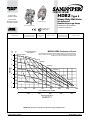
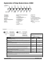
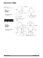
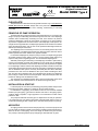
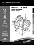
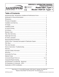
SERVICE & OPERATING MANUAL
Original Instructions
See pages 18 & 19
IIfor2GD
T5
ATEX ratings
Model HDB2 Type 3
Table of Contents
Engineering Data and Performance Curve............................................................ 1
Explanation of Pump Nomenclature and Temperature Limitations......................... 2
Dimensions............................................................................................................. 3
Principle of Operation............................................................................................. 4
Installation and Start-Up......................................................................................... 4
Air Supply............................................................................................................... 4
Installation Guide.................................................................................................... 5
Air Inlet & Priming................................................................................................... 6
Air Exhaust............................................................................................................. 6
Between Uses........................................................................................................ 6
Check Valve Servicing............................................................................................ 6
Diaphragm Servicing.............................................................................................. 6
Air Valve Lubrication............................................................................................... 7
ESADS+Plus®: Externally Serviceable Air Distribution System................................. 7
Pilot Valve............................................................................................................... 8
Pilot Valve Actuator................................................................................................. 8
Service Instructions: Troubleshooting ................................................................... 9
Warranty................................................................................................................. 9
Recommended Accessories, Available Service Kits............................................... 9
Important Safety Information................................................................................ 10
Recycling.............................................................................................................. 10
Grounding The Pump........................................................................................... 11
Material Codes..................................................................................................... 12
Composite Repair Parts List............................................................................13-15
Composite Repair Drawing.................................................................................. 16
CE Declaration of Conformity - Machinery........................................................... 17
CE Declaration fo Conformity - ATEX................................................................... 18
Explanation of ATEX Certification......................................................................... 19
Warren Rupp, Inc. • A Unit of IDEX Corporation • 800 N. Main St., Mansfield, Ohio 44902 USA
Telephone (419) 524-8388 • Fax (419) 522-7867 • warrenrupp.com
hdb2dl3sm-rev0515
©Copyright 2015 Warren Rupp, Inc. All rights reserved.
HDB2 Type 3
Quality System
ISO9001 Certified
Heavy Duty Ball Valve
Environmental
Management System
ISO14001 Certified
Air-Operated
Double Diaphragm Pump
Top Discharge Porting
Bottom Discharge Porting
ENGINEERING, PERFORMANCE
& CONSTRUCTION DATA
See pages 18 & 19
IIfor2GD
T5
ATEX ratings
7
HEAD
6
90
80
70
4
60
3
2
1
0
SOLIDS-HANDLING
HEADS UP TO
DISPLACEMENT/STROKE
Up to 3/8 in. (9mm)
125 psi or 289 ft. of water
(8.8 Kg/cm2 or 88 meters)
.43 Gallon / 1.63 liter
MODEL HDB2 Performance Curve
Performance based on the following: elastomer fitted pump, flooded suction,
water at ambient conditions. The use of other materials and varying hydraulic
conditions may result in deviations in excess of 5%.
50(85)
60(101.9)
70(118.9)
80 PSI
80(135.9)
60 PSI
50
40
90(152.9)
95(161.4)
40 PSI
30
100(169.9)
20
20 PSI Air Inlet
10
0
AIR VALVE
No-lube, no-stall
design
10(17) 20(34)
30(51)
100 PS
I
40(68)
100
5
CAPACITY
0 to 135 gallons per minute
(0 to 511 liters per minute)
AIR CONSUMPTION
SCFM (M3/hr)
PSI
BAR
INTAKE/DISCHARGE PIPE SIZE
2 " (50mm) NPT (F)
0
0
Pressure
20
40
100
60
80
U.S. Gallons per minute
200
300
Liters per minute
100
400
140
120
500
CAPACITY
SANDPIPER® pumps are designed to be powered only by compressed air.
hdb2smdl3sm-rev0515
Model HDB2 Page 1
Explanation of Pump Nomenclature, HDB2
Your Model
#:
(fill in from pump
nameplate)
____
_____
___________
PumpPumpPump
DischargeDiaphragm/ Design
Options
Construction
Series
Design
Size
Porting
ValveLevel
Model
#:
XXX
XXXX,
XXXXXXX
Pump Series
S SANDPIPER®
Pump Design
B Soilid Ball
Pump Size
2
2"
D
S
ET
ES
Bottom
Side
Dual Top
Dual Side
Discharge Porting Position
Diaphragm Check Valve Materials
B Nitrile
C FKM with PTFE
F FDA Accepted White Nitrile
GN Neoprene Backup with PTFE Overlay
and PTFE Check Balls
GR Hytrel Backup w/
PTFE Overlay/PTFE Balls
GZ PTFE/Nitrile Bonded
One-Piece/PTFE Balls
H EPDM with PTFE
NNeoprene
R Hytrel
SSantoprene
U Santoprene with PTFE
V FKM
Design Level
3
Construction
A Aluminum Wetted, Aluminum Air
SI Stainless Steel Wetted, Cast Iron Air
SS Stainless Steel Wetted, Aluminum Air
HC Alloy-C Wetted, Aluminum Air
HI Alloy-C Wetted, Cast Iron Air
Options
P1 Intrinsically Safe ATEX Compliant
Pulse Output
Your Serial #: (fill in from pump nameplate)______________________________________
Models equipped with
Cast Iron, Stainless
II 1 D c T100oC Steel, or Alloy C wetted
parts, and Cast Iron midI M1 c
section parts. See page
I M2 c
19 for ATEX Explanation
of EC-Type Certificate.
II 1 G c T5
IIII 3/1
2GD
T5
G c T5
All models, including
pumps equipped with
II 2 D c T100oC Aluminum wetted and
midsection parts.
See page 19 for ATEX
Explanation of Type
Examination Certificate.
II 2 G c T5
IIII 3/2
2GD
T5
G c T5
Materials
Maximum and Minimum Temperatures are the limits for which
these materials can be operated. Temperatures coupled with
pressure affect the longevity of diaphragm pump components.
Maximum life should not be expected at the extreme limits of
the temperature ranges.
Operating Temperatures
Maximum
Minimum
190°F
88°C
-10°F
-23°C
EPDM Shows very good water and chemical resistance. Has poor resistance to oil and solvents, but is fair in
ketones and alcohols.
280°F
138°C
-40°F
-40°C
NEOPRENE All purpose. Resistant to vegetable oils. Generally not affected by moderate chemicals, fats,
greases and many oils and solvents. Generally
attacked by strong oxidizing acids, ketones, esters, nitro hydrocarbons and chlorinated aromatic hydrocarbons.
200°F
93°C
-10°F
-23°C
HYTREL® Good on acids, bases, amines and glycols at room temperature.
220°F
104°C
-20°F
-29°C
PTFE Chemically inert, virtually impervious. Very few chemicals are known to react chemically with
PTFE: molten alkali metals, turbulent liquid or gaseous fluorine and a few fluoro-chemicals such as
chlorine trifluoride or oxygen difluoride which readily liberate free fluorine at elevated temperatures.
FKM (Fluorocarbon) shows good resistance to a wide range of oils and solvents; especially all aliphatic,
aromatic and halogenated hydrocarbons, acids, animal
and vegetable oils. Hot water or hot aqueous solutions (over 70°F) will attack FKM.
220°F
104°C
-35°F
-37°C
350°F
177°C
-40°F
-40°C
Santoprene® Injection molded thermoplastic elastomer with no fabric layer. Long mechanical flex life. Excellent abrasion resistance.
275°F
135°C
-40°F
-40°C
Nitrile General purpose, oil-resistant. Shows good solvent, oil, water and hydraulic fluid resistance. Should
not be used with highly polar solvents
like acetone and MEK, ozone, chlorinated hydrocarbons and nitro hydrocarbons.
‡ CF-8M Stainless Steel equal to or exceeding ASTM specification A743 for corrosion resistant iron chro-
mium, iron chromium nickel, and nickel based alloy castings for general applications. Commonly referred
to as 316 Stainless Steel in the pump industry.
ALLOY C CW-12MW equal to or exceeding ASTM A494 specification for nickel and nickel alloy castings.
For specific applications, always consult “Chemical Resistance Chart" Technical Bulletin
hdb2smdl3sm-rev0515
Model HDB2 Page 2
Dimensions: HDB2
DISCHARGE PORT
2” NPT(F)
Dimensions are ± 1/8"
Figures in parenthesis = millimeters
TOP
DISCHARGE
PORTING
AIR INLET
3/4” NPT(F)
SUCTION PORT
2” NPT(F)
*Indicates dimensions with suction
and discharge ports rotated 180°
to a vertical position.
AIR EXHAUST
3/4” NPT(F)
(11)
7/16” DIA.
MOUNTING HOLES
TYP. (8) PLACES
Dimension
A
B
Standard Pump 23 ¼" (590) 14 1/16" (357)
13
5
Pulse Output Kit 23 /16" (605)14 /8" (371)
* INDICATES DIMENSIONS WITH SUCTION AND DISCHARGE
PORTS ROTADED 180° TO A VERTICAL POSITION.
AIR INLET
3/4” NPT(F)
BOTTOM
DISCHARGE
PORTING
DISCHARGE PORT
2” NPT(F)
AIR EXHAUST
3/4” NPT(F)
*Indicates dimensions with suction
and discharge ports rotated 180°
to a vertical position.
SUCTION PORT
2” NPT(F)
(11)
7/16” DIA.
MOUNTING HOLES
TYP. (8) PLACES
* INDICATES DIMENSIONS WITH SUCTION AND DISCHARGE
PORTS ROTADED 180° TO A VERTICAL POSITION.
hdb2smdl3sm-rev0515
Model HDB2 Page 3
SERVICE & OPERATING MANUAL
Original Instructions
See pages 18 & 19
IIfor2GD
T5
ATEX ratings
Model HDB2 Type 3
PLEASE NOTE!
The photos shown in this manual are for general instruction only. YOUR SPECIFIC
MODEL MAY NOT BE SHOWN. Always refer to the parts list and exploded view
drawing for your specific model when installing, disasembling or servicing
your pump.
PRINCIPLE OF PUMP OPERATION
This ball check valve pump is powered by compressed air and is a 1:1 pressure ratio
design. The pump is alternately pressurize through the inner side of one diaphragm
chamber, while simultaneously exhausting the other inner chamber. Air pressure
causes the diaphragms, (which are connected by a common rod,) to move endwise.
Air pressure is applied over the entire surface of the diaphragm, while liquid is discharged from the opposite side. The diaphragm operates under a balanced condition
during the discharge stroke, and the unit can be operated at discharge heads over
200 feet (61 meters) of water head.
The diaphragms are connected by a common rod, secured by plates to the center
of the diaphragms. One diaphragm performs the discharge stroke, while the other is
pulled to perform the suction stroke in the opposite chamber.
For maximum diaphragm life, keep the pump as close to the liquid being pumped
as possible. Positive suction head in excess of 10 feet of liquid (3.048 meters) may
require a back pressure regulating device. This will maximize diaphragm life.
Alternate pressuring and exhausting of the diaphragm chamber is performed by
means of an externally mounted, pilot operated, four-way spool type air distribution
valve. When the spool shifts to one end of the valve body, inlet air pressure is applied
to one diaphragm chamber and the other diaphragm chamber exhausts air. When the
spool shifts to the opposite end of the valve body, the porting of chambers is reversed.
The air distribution valve spool is moved by an internal pilot valve which alternately
pressurizes one side of the air distribution valve spool, while exhausting the other
side. The pilot valve is shifted at each end of the diaphragm stroke by the diaphragm
plate coming in contact with the end of the pilot spool. This pushes the pilot valve into
position for shifting of the air distribution valve.
The chambers are manifolded together with a suction and discharge check valve
for each chamber which maintains flow in one direction through the pump.
INSTALLATION & START-UP
Locate the pump as close to the product being pumped as possible. Keep suction
line length and number of fittings to a minimum. Do not reduce line size.
For installations of rigid piping, short flexible sections of hose should be installed
between pump and piping. This reduces vibration and strain to the piping system.
A Warren Rupp Tranquilizer® surge suppressor is recommended to further reduce
pulsation in flow.
This pump was tested at the factory prior to shipment and is ready for operation.
It is self-priming from a dry start for suction lifts of 20 feet (6.096 meters) or less. For
suction lifts exceeding 20 feet of liquid, fill the chambers with liquid prior to priming.
AIR SUPPLY
Air supply pressures cannot exceed 125 psi (8.61 bar). Connect the pump air inlet
to an air supply of sufficient capacity and pressure required for desired performance.
When the air line is solid piping, use a short length of flexible hose [not less than
3/4" (19mm) in diameter] between pump and piping to eliminate strain to pipes.
hdb2smdl3sm-rev0515
Model HDB2 Page 4
INSTALLATION GUIDE
Top Discharge Ball or Flap Valve Unit
CAUTION
Available from
Warren Rupp
The air exhaust should be
piped to an area for safe
disposition of the product
being pumped, in the event
of a diaphragm failure.
1 Tranquilizer®/Surge Supressor
2 Filter/Regulator�
1
Surge
Suppressor
2
hdb2smdl3sm-rev0515
Model HDB2 Page 5
AIR INLET & PRIMING
For start-up, open an air valve approximately 1/2" to 3/4" turn. After the unit primes,
an air valve can be opened to increase flow as desired. If opening the valve increases
cycling rate, but does not increase flow rate, cavitation has occurred, and the valve
should be closed slightly.
For the most efficient use of compressed air and the longest diaphragm life, throttle
the air inlet to the lowest cycling rate that does not reduce flow.
AIR EXHAUST
If a diaphragm fails, the pumped liquid or fumes can enter the air end of the pump,
and be exhausted into the atmosphere. When pumping hazardous or toxic materials,
pipe the exhaust to an appropriate area for safe disposition.
This pump can be submerged if materials of construction are compatible with the
liquid. The air exhaust must be piped above the liquid level. Piping used for the air
exhaust must not be smaller than 1" (2.54 cm). Reducing the pipe size will restrict
air flow and reduce pump performance .When the product source is at a higher level
than the pump (flooded suction), pipe the exhaust higher than the product source to
prevent siphoning spills.
Freezing or icing-up of the air exhaust can occur under certain temperature and
humidity conditions. Use of an air dryer unit should eliminate most icing problems.
BETWEEN USES
When used for materials that tend to settle out or transform to solid form, the pump
should be completely flushed after each use, to prevent damage. Product remaining
in the pump between uses could dry out or settle out. This could cause problems
with valves and diaphragms at re-start. In freezing temperatures, the pump must be
drained between uses in all cases.
CHECK VALVE SERVICING
For best priming and most efficient pumping performance, it is important to maintain
check valves and valve seats in good condition for proper sealing. Need for inspection
or service of ball valves is usually indicated by poor priming, unstable cycling, reduced
performance, or pump cycles but will not pump.
Inspection and service of check valves requires the removal of five hex nuts and
one capscrew for each set of check valves (i.e., suction & discharge), providing
access to the two ball valves and their valve seats. New ball valves are 35/8" (9.21 cm)
in diameter and will require replacement when worn to approximately 33/8" (8.57 cm)
diameter.
DIAPHRAGM SERVICING
Need for inspection or service of diaphragm is usually indicated when unit pumps
from one chamber only and air is discharged out pump discharge port or when liquid
being pumped is discharged through air exhaust port.
To service diaphragms remove two capscrews which secure the chamber to the
manifold assembly, and twelve hex nuts that secure the chamber to the main pump
assembly. To remove diaphragms, loosen diaphragm assembly by turning it out of
the diaphragm rod using a 11/8" (2.857 cm) socket or wrench. Removal of opposite
outer chamber will permit removal of second diaphragm assembly and diaphragm rod
as a unit.
To remove the diaphragm from the diaphragm assembly, hold the diaphragm rod
in a clamping device, making sure to protect the rod surface of shaft so as not to
scratch or damage it in any way. With a wrench turn the diaphragm assembly out of the
diaphragm rod. To disassemble the components, turn a 5/16-18 UNC capscrew by
hand into the tapped hole in the inner diaphragm plate. This will keep the plate from
turning while the capscrew is removed. To remove the capscrew, place the assembly
in a vise so the two protruding ends of screws are loose in the vise jaws (approximately
7/8" apart). Turn the center screw loose from the back plate and the assembly will
come apart.
hdb2smdl3sm-rev0515
Model HDB2 Page 6
REASSEMBLY
All procedures for reassembling the pump are the reverse of the disassembly
instructions with further instructions as shown:
The diaphragm assemblies are to be installed with the natural bulge outward or
toward the head of the center screw. Make sure both plates are installed with outer radii
against the diaphragm. After all components are in position in a vise and hand tight,
set a torque wrench for 40 ft. pounds (54.23 Newton meters) using a 11/8" (2.857 cm)
socket. After each diaphragm sub assembly has been completed, thread one assembly
into the diaphragm rod. Make sure the 5/16-18 UNC capscrew has been removed
from the inner plate and the diaphragm rod bumper is in place on the diaphragm rod.
Install this sub assembly into the pump and secure by installing the outer chamber
in place and tightening the capscrews. This will hold the assembly in place while the
opposite side is installed. Install the second diaphragm assembly into the diaphragm
rod checking to see that the diaphragm rod bumper is in place. Tighten to 30 ft. lbs.
(40.67 Newton meters) torque before installing the outer chamber in place. If the holes
in the diaphragm flange do not align with the holes in the inner chamber flange, turn
the diaphragm assembly in the direction of tightening to align the holes so that the
capscrews can be inserted. This final torquing of the last diaphragm assembly will lock
the two diaphragm assemblies together. Secure the last outer chamber by tightening
down the securing nuts gradually and evenly. This tightening procedure should be
done on both sides.
When reinstalling check valves, take care that the seat gaskets are aligned properly
before securing porting flange in place.
A Note about Air Valve Lubrication
The SANDPIPER pump’s pilot valve and main air valve assemblies are designed
to operate WITHOUT lubrication. This is the preferred mode of operation. There
may be instances of personal preference, or poor quality air supplies when lubrication of the compressed air supply is required. The pump air system will operate with
properly lubricated compressed air supplies. Proper lubrication of the compressed air
supply would entail the use of an air line lubricator (available from Warren Rupp) set
to deliver one drop of 10 wt., non-detergent oil for every 20 SCFM of air the pump
consumed at its point of operation. Consult the pump’s published Performance Curve to
determine this.
It is important to remember to inspect the sleeve and spool set routinely. It should
move back and forth freely. This is most important when the air supply is lubricated.
If a lubricator is used, oil accumulation will, over time, collect any debris from the
compressed air. This can prevent the pump from operating properly.
Water in the compressed air supply can create problems such as icing or freezing of the exhaust air causing the pump to cycle erratically, or stop operating. This
can be addressed by using a point of use air dryer to supplement a plant’s air drying
equipment. This device will remove excess water from the compressed air supply and
alleviate the icing or freezing problem.
ESADS+Plus®: Externally Serviceable Air Distribution
System
Please refer to the exploded view drawing and parts list in the Service Manual
supplied with your pump. If you need replacement or additional copies, contact your
local Warren Rupp Distributor, or the Warren Rupp factory Literature Department at
the number shown below. To receive the correct manual, you must specify the MODEL
and TYPE information found on the name plate of the pump.
The main air valve sleeve and spool set is located in the valve body mounted on
the pump with four hex head capscrews. The valve body assembly is removed from
the pump by removing these four hex head capscrews.
With the valve body assembly off the pump, access to the sleeve and spool set is
made by removing four hex head capscrews (each end) on the end caps of the valve
body assembly. With the end caps removed, slide the spool back and forth in the
sleeve. The spool is closely sized to the sleeve and must move freely to allow for proper
pump operation. An accumulation of oil, dirt or other contaminants from the pump’s
air supply, or from a failed diaphragm, may prevent the spool from moving freely.
hdb2smdl3sm-rev0515
Model HDB2 Page 7
This can cause the spool to stick in a position that prevents the pump from operating.
If this is the case, the sleeve and spool set should be removed from the valve body
for cleaning and further inspection.
Remove the spool from the sleeve. Using an arbor press or bench vise (with an
improvised mandrel), press the sleeve from the valve body. Take care not to damage
the sleeve. At this point, inspect the o-rings on the sleeve for nicks, tears or abrasions.
Damage of this sort could happen during assembly or servicing. A sheared or cut
o-ring can allow the pump’s compressed air supply to leak or bypass within the air
valve assembly, causing the pump to leak compressed air from the pump air exhaust
or not cycle properly. This is most noticeable at pump dead head or high discharge
pressure conditions. Replace any of these o-rings as required or set up a routine,
preventive maintenance schedule to do so on a regular basis. This practice should
include cleaning the spool and sleeve components with a safety solvent or equivalent,
inspecting for signs of wear or damage, and replacing worn components.
To re-install the sleeve and spool set, lightly lubricate the o-rings on the sleeve
with an o-ring assembly lubricant or lightweight oil (such as 10 wt. air line lubricant).
Press the set into the valve body easily, without shearing the o-rings. Re-install one
end cap, gasket and bumper on the valve body. Using the arbor press or bench vise
that was used in disassembly, press the sleeve back into the valve body. You may
have to clean the surfaces of the valve body where the end caps mount. Material
may remain from the old gasket. Old material not cleaned from this area may cause
air leakage after reassembly. Take care that the bumper stays in place allowing the
sleeve to press in all the way. Re-install the spool, the opposite end cap, gasket and
bumper on the valve body. After inspecting and cleaning the gasket surfaces on the
valve body and intermediate, re-install the valve body on the pump using new gaskets.
Tighten the four hex head capscrews evenly and in an alternating cross pattern.
PILOT VALVE
The pilot valve assembly is accessed by removing the main air distribution valve
body from the pump and lifting the pilot valve body out of the intermediate housing.
Most problems with the pilot valve can be corrected by replacing the o-rings.
Always grease the spool prior to inserting it into the sleeve. If the sleeve is removed
from the body, reinsertion must be at the chamfered side. Grease the o-rings to slide
the sleeve into the valve body. Securely insert the retaining ring around the sleeve.
When reinserting the pilot valve, push both plungers (located inside the intermediate
bracket) out of the path of the pilot valve spool ends to avoid damage.
PILOT VALVE ACTUATOR
Bushings for the pilot valve actuators are threaded into the intermediate bracket
from the outside. The plunger may be removed for inspection or replacement. First
remove the air distribution valve body and the pilot valve body from the pump. The
plungers can be located by looking into the intermediate. It may be necessary to
use a fine piece of wire to pull them out. The bushing can be turned out through the
inner chamber by removing the outer chamber assembly. Replace the bushings if
pins have bent.
hdb2smdl3sm-rev0515
Model HDB2 Page 8
TROUBLESHOOTING
PROBLEM: Pump cycles but will not pump. (Note: higher suction lifts require faster cycling speed for priming.)
POSSIBLE CAUSES:
A. Air leak in suction line.
B. Excessive suction lift.
C. Check valve not closing.
D. Leakage at joint of suction manifold or elbow flange.
E. Suction line plugged.
F. Diaphragm ruptured.
PROBLEM: Pump will not cycle. (Note: Always disconnect air supply to relieve air pressure before disassembling
any portion of pump.)
POSSIBLE CAUSES:
A. Discharge hose or line plugged, or discharge head requirement greater than air supply pressure.
(Disconnect discharge line to check.)
B. Spool in air distribution valve not shifting. (Remove end cap and check spool — must slide freely.)
C. Diaphragm ruptured. (Air will escape out discharge line in this case.)
D. Blockage in diaphragm chamber preventing movement. (Shut off air supply and reopen after pressure is relieved.)
E. Plugged or dirty exhaust muffler.
PROBLEM: Uneven discharge flow. (Indicates one chamber not operating properly.)
POSSIBLE CAUSES:
A. Check valve not sealing properly in one chamber.
B. Diaphragm failure in one chamber.
C. Air leak at suction manifold joint or elbow flange one side.
D. Plugged or dirty muffler.
For additional information, see the Warren Rupp Troubleshooting Guide.
WARRANTY:
This unit is guaranteed for a period of five years against defective material and workmanship.
RECOMMENDED WARREN RUPP ACCESSORIES
TO MAXIMIZE PUMP PERFORMANCE:
•Tranquilizer® Surge Suppressor: For nearly pulse-free flow.
• Warren Rupp Filter/Regulator: For modular installation and service
convenience.
• Warren Rupp Speed Control: For manual or programmable process
control. Manual adjustment or 4-20mA reception.
For more detailed information on these accessories,
contact your local Warren Rupp Factory-Authorized Distributor,
or Warren Rupp corporate headquarters.
Available Service Kits
Part No.
Description
Air End Kit
476-247-000
Seals, O-Rings, Gaskets, Sleeve and Spool Set, Plungers,
Bushings, Pilot Valve Assembly
Santoprene Diaphragms, Check Balls, Gaskets, Seals, Nitrile O-Rings
476-245-354
476-245-360
Nitrile Diaphragms, Weighted Check Balls, O-Rings, Gaskets,
Seals, Wear Pads
476-245-364
EPDM Diaphragms and Weighted Check Balls, Gaskets, Seals,
Wear Pads, Nitrile O-Rings
476-245-365
Neoprene Diaphragms and Weighted Check Balls, Gaskets, Seals,
Wear Pads, Nitrile O-Rings,
476-245-633
FKM Diaphragms, PTFE Check Balls, Gaskets and O-Rings,
Seals, Wear Pads
476-043-635
PTFE Overlay Diaphragms, Check Balls, Gaskets and O-Rings,
Seals, Neoprene Backup Diaphragm
hdb2smdl3sm-rev0515
Model HDB2 Page 9
IMPORTANT SAFETY
INFORMATION
IMPORTANT
Read these safety warnings
and instructions in this
manual completely, before
installation and start-up
of the pump. It is the responsibility of the
purchaser to retain this manual for reference.
Failure to comply with the recommendations
stated in this manual will damage the pump,
and void factory warranty.
WARNING
Take action to prevent static
sparking. Fire or explosion
can result, especially when
handling flammable liquids.
The pump, piping, valves,
containers or other miscellaneous equipment
must be grounded. (See page 11)
WARNING
This pump is pressurized
internally with air pressure
during operation. Always
make certain that all bolting
is in good condition and
that all of the correct
bolting is reinstalled during assembly.
CAUTION
WARNING
Before pump operation,
inspect all gasketed
fasteners for looseness
caused by gasket creep. Retorque loose fasteners to
prevent leakage. Follow recommended torques
stated in this manual.
CAUTION
Pump not designed,
tested or certified to be
powered by compressed
natural gas. Powering
the pump with natural
gas will void the warranty.
WARNING
When used for toxic or
aggressive fluids, the pump
should always be flushed
clean prior to disassembly.
WARNING
Before doing any maintenance on the pump,
be certain all pressure is
completely vented from the
pump, suction, discharge,
piping, and all other
openings and connections. Be certain the air
supply is locked out or made non‑operational,
so that it cannot be started while work is being
done on the pump. Be certain that approved
eye protection and protective clothing are worn
all times in the vicinity of the pump. Failure to
follow these recommendations may result in
serious injury or death.
Before maintenance or
repair, shut off the compressed air line, bleed the
pressure, and disconnect
the air line from the pump.
The discharge line may be
pressurized and must be bled of its pressure.
WARNING
Airborne particles and
loud noise hazards.
Wear ear and eye
protection.
WARNING
In the event of diaphragm
rupture, pumped material
may enter the air end of the
pump, and be discharged
into the atmosphere. If
pumping a product which is hazardous or toxic,
the air exhaust must be piped to an appropriate
area for safe disposition.
WARNING
Use safe practices
when lifting
kg
RECYCLING
Many components of SANDPIPER® AODD pumps are made
of recyclable materials (see chart on page 11 for material
specifications). We encourage pump users to recycle worn out parts
and pumps whenever possible, after any hazardous pumped fluids
are thoroughly flushed.
hdb2smdl3sm-rev0515
Model HDB2 Page 10
Grounding The Pump
WARNING
Take action to prevent static sparking. Fire or explosion can result,
especially when handling flammable
liquids. The pump, piping, valves,
containers or other miscellaneous
equipment must be grounded.
One eyelet is fastened to the pump hardware.
One eyelet is installed to a true earth ground.
This 8 foot long (244 centimeters) Ground
Strap, partnumber 920-025-000 can be
ordered as a service item.
To reduce the risk of static electrical sparking, this pump must be grounded.
Check the local electrical code for detailed grounding instruction and the
type of equipment required, or in the absence of local codes, an industry
or nationally recognized code having juristiction over specific installations.
hdb2smdl3sm-rev0515
Model HDB2 Page 11
MATERIAL CODES
THE LAST 3 DIGITS OF PART NUMBER
000
010
012
015
020
025
080
100
110
111
112
113
114
115
117
120
123
148
149
150
151
152
154
155
156
157
158
159
162
165
166
170
175
180
305
306
307
308
309
310
313
330
331
332
333
335
336
337
340
342
351
Assembly, sub-assembly;
and some purchased items
Cast Iron
Powered Metal
Ductile Iron
Ferritic Malleable Iron
Music Wire
Carbon Steel, AISI B-1112
Alloy 20
Alloy Type 316 Stainless Steel
Alloy Type 316 Stainless Steel
(Electro Polished)
Alloy C
Alloy Type 316 Stainless Steel
(Hand Polished)
303 Stainless Steel
302/304 Stainless Steel
440-C Stainless Steel (Martensitic)
416 Stainless Steel
(Wrought Martensitic)
410 Stainless Steel
(Wrought Martensitic)
Hardcoat Anodized Aluminum
2024-T4 Aluminum
6061-T6 Aluminum
6063-T6 Aluminum
2024-T4 Aluminum (2023-T351)
Almag 35 Aluminum
356-T6 Aluminum
356-T6 Aluminum
Die Cast Aluminum Alloy #380
Aluminum Alloy SR-319
Anodized Aluminum
Brass, Yellow, Screw Machine Stock
Cast Bronze, 85-5-5-5
Bronze, SAE 660
Bronze, Bearing Type, Oil Impregnated
Die Cast Zinc
Copper Alloy
Carbon Steel, Black Epoxy Coated
Carbon Steel, Black PTFE Coated
Aluminum, Black Epoxy Coated
Stainless Steel, Black PTFE Coated
Aluminum, Black PTFE Coated
PVDF Coated
Aluminum, White Epoxy Coated
Zinc Plated Steel
Chrome Plated Steel
Aluminum, Electroless Nickel Plated
Carbon Steel, Electroless
Nickel Plated
Galvanized Steel
Zinc Plated Yellow Brass
Silver Plated Steel
Nickel Plated
Filled Nylon
Food Grade Santoprene; Color: NATURAL
hdb2smdl3sm-rev0515
353
354
Geolast; Color: BLACK
Injection Molded #203-40
Santoprene- Duro 40D +/-5; Color: RED
355
Thermal Plastic
356
Hytrel; Color: BLUE
357
Injection Molded Polyurethane;
Color: GREEN
358
Urethane Rubber; Color: NATURAL
(Some Applications)
(Compression Mold)
359
Urethane Rubber; Color: NATURAL
360
Nitrile Rubber; Color Coded: RED
361Nitrile
363
FKM (Fluorocarbon).
Color Coded: YELLOW
364
E.P.D.M. Rubber. Color Coded: BLUE
365
Neoprene Rubber;
Color Coded: GREEN
366
Food Grade Nitrile; Color: WHITE
Food Grade EPDM; Color: GRAY
368
Butyl Rubber
370
Color Coded: BROWN
371
Philthane (Tuftane)
374
Carboxylated Nitrile
375
Fluorinated Nitrile
378
High Density Polypropylene
379
Conductive Nitrile;
Color Coded: RED & SILVER
Conductive Neoprene;
384
Color Coded: GREEN & SILVER
Cellulose Fibre
405
408
Cork and Neoprene
425
Compressed Fibre
426
Blue Gard
440
Vegetable Fibre
465Fibre
500
Delrin 500
501
Delrin 570
502
Conductive Acetal, ESD-800;
Color: BLACK
503
Conductive Acetal, Glass-Filled
Color: BLACK; Color Coded: YELLOW
505
Acrylic Resin Plastic
506
Delrin 150
520
Injection Molded PVDF; Color: NATURAL
521
Injection Molded Conductive PVDF;
Color: BLACK; Color Coded: LIGHT
GREEN
540Nylon
541Nylon
542Nylon
544
Nylon Injection Molded
550Polyethylene
551
Glass Filled Polypropylene; Color: BLACK
552
Unfilled Polypropylene; Color: NATURAL
555
Polyvinyl Chloride
556
Black Vinyl
557
Conductive Polypropylene;
Color: BLACK; Color Coded: SILVER
558
Conductive HDPE; Color: BLACK
Color Coded: SILVER
559
Conductive Polypropylene; Color: BLACK
Color Coded: SILVER
570
Rulon II
580Ryton
590Valox
591
Nylatron G-S
592
Nylatron NSB
600
PTFE (virgin material)
Tetrafluorocarbon (TFE)
601
PTFE (Bronze and moly filled)
602
Filled PTFE
603
Blue Gylon
604PTFE
606PTFE
607Envelon
Conductive PTFE; Color: BLACK
608
610
PTFE Encapsulated Silicon
611
PTFE Encapsulated FKM
632Neoprene/Hytrel
633FKM/PTFE
634EPDM/PTFE
635Neoprene/PTFE
637
PTFE , FKM/PTFE
638
PTFE , Hytrel/PTFE
639Nitrile/TFE
643Santoprene®/EPDM
644Santoprene®/PTFE
656
Santoprene Diaphragm and
Check Balls/EPDM Seats
661EPDM/Santoprene
666
FDA Nitrile Diaphragm,
PTFE Overlay, Balls, and Seals
668
PTFE, FDA Santoprene/PTFE
Delrin is a registered
tradename of E.I. DuPont.
Gylon is a registered tradename
of Garlock, Inc.
Nylatron is a registered tradename
of Polymer Corp.
Santoprene is a registered tradename
of Exxon Mobil Corp.
Rulon II is a registered tradename
of Dixion Industries Corp.
Ryton is a registered tradename
of Phillips Chemical Co.
Valox is a registered tradename
of General Electric Co.
PortaPump, Tranquilizer and SludgeMaster are
registered tradenames of Warren Rupp, Inc.
Model HDB2 Page 12
Composite Repair Parts List
ITEM
NO.
PART NUMBER
DESCRIPTION
1
1
2
3
4
5
6
7
7-A
7-B
7-C
7-D
7-E
7-F
8
9
10
11
12
13
14
15
16
17
18
19
20
21
22
25
26
27
28
29
30
31
32
33
34
35
36
37
38
114.002.010.
114.002.156.
070.006.170.
720.004.360.
135.016.162.
560.001.360.
620.011.114.
095.073.001.
095.070.558.
755.025.000.
560.033.360.
775.026.000.
560.023.360.
675.037.080.
360.041.379.
530.036.000.
031.012.000.
095.043.010.
095.043.156.
132.014.358.
165.011.010.
165.011.157.
360.010.425.
560.020.360.
170.032.330.
170.045.330.
360.048.425.
132.002.360.
560.022.360.
685.007.120.
612.047.330.
170.060.330.
170.024.330.
170.058.330.
170.030.330.
807.038.330.
807.039.330.
900.005.330.
900.003.330.
900.006.330.
545.007.330.
545.008.330.
545.005.330.
196.001.010.
196.001.157.
115.053.080.
hdb2smdl3sm-rev0515
TOTAL
RQD.
Bracket Assembly, Intermediate
1
Bracket Assembly, Intermediate
1
Bearing, Sleeve
2
Seal, U-Cup
2
Bushing Assembly, Threaded
2
O-Ring
2
Plunger, Actuator
2
Pilot Valve Body Assy.11
Pilot Valve Body
1
Sleeve (w/O-Ring)
1
O-Ring (Sleeve)
4
Spool (w/O-Ring)
1
O-Ring (Spool)
2
Retaining Ring
1
Gasket, Valve Body
1
Muffler, Exhaust
1
Sleeve & Spool Set
1
Body, Valve
1
Body, Valve
1
Bumper, Valve Spool
2
Cap, End
2
Cap, End
2
Gasket, End Cap
2
O-Ring
6
Capscrew, Hex Head
8
Capscrew, Hex Head
4
Gasket, Valve Body
1
Bumper, Diaphragm
2
O-Ring
2
Rod, Diaphragm
1
Plate, Diaphragm — Inner
2
Capscrew, Hex Head
16
Capscrew, Hex Head
4
Capscrew, Hex Head
4
Capscrew, Hex Head
8
Stud
4
Stud
12
Washer, Lock
4
Washer, Lock
20
Washer, Lock
12
Nut, Hex
12
Nut, Hex
12
Nut, Hex
4
Chamber, Inner
2
Chamber, Inner
2
Bracket, Foot Mounting
2
Model HDB2 Page 13
ITEM
NO.
PART NUMBER
DESCRIPTION
39
560.047.360.
O-Ring
560.060.611.
O-Ring
40
685.032.080.
Rod, Connector
41
722.035.110.
Seat Assembly, Ball Check Valve
(for use with PTFE balls only)
722.035.112.
Seat Assembly, Ball Check Valve
(for use with PTFE balls only)
722.097.110.
Seat Assembly
722.097.112.
Seat Assembly
42
286.007.360.
Diaphragm
286.007.364.
Diaphragm
286.007.365.Diaphragm
286.007.363.
Diaphragm
286.007.366.
Diaphragm
286.007.356.
Diaphragm
286.007.354.
Diaphragm
43
196.035.010.
Chamber, Diaphragm — Outer
196.035.110.
Chamber, Diaphragm — Outer
196.035.112.
Chamber, Diaphragm — Outer
196.035.156.
Chamber, Diaphragm — Outer
44
612.039.010.
Plate Assembly, Diaphragm
612.097.110.
Plate Assembly, Diaphragm
612.097.112.
Plate Assembly, Diaphragm
612.039.157.
Plate Assembly, Diaphragm
45
312.033.010.
Elbow, Manifold
312.033.110.
Elbow, Manifold
312.033.112.
Elbow, Manifold
312.033.156.
Elbow, Manifold
46
334.025.010.
Flange, Threaded
334.025.110.
Flange, Threaded
334.025.112.
Flange, Threaded
334.025.156.
Flange, Threaded
47
334.026.010.
Flange, Porting — Suction
334.026.110.
Flange, Porting — Suction
334.026.112.
Flange, Porting — Suction
334.026.156.
Flange, Porting — Suction
48
334.027.010.
Flange, Porting — Discharge
334.027.110.
Flange, Porting — Discharge
334.027.112.
Flange, Porting — Discharge
334.027.156.
Flange, Porting — Discharge
49
518.027.010.
Manifold
518.027.110.
Manifold
518.027.112.
Manifold
518.027.156.
Manifold
ITEM
hdb2smdl3sm-rev0515
TOTAL
RQD.
2
2
1
2
2
2
2
2
2
2
2
2
2
2
2
2
2
2
2
2
2
2
2
2
2
2
2
2
1
1
1
1
1
1
1
1
1
1
1
1
TOTAL
Model HDB2 Page 14
NO.
PART NUMBER
DESCRIPTION
50
51
52
53
54
55
56
57
58
59
62
63
360.049.425.
360.049.603.
360.050.379.
360.050.384.
360.050.608.
618.003.110.
618.003.112.
618.003.330.
675.013.360.
675.013.365.
675.013.363.
675.013.364.
675.013.600.
050.017.360W.
050.017.364W.
050.017.354.
050.017.365W.
050.018.600.
115.057.080.
900.004.330.
545.004.330.
286.020.604.
901.025.115.
618.003.330.
570.009.360.
570.009.363.
570.009.364.
570.009.365.
Gasket, Flange
Gasket, Flange
Gasket, Manifold
Gasket, Manifold
Gasket, Manifold
Pipe Plug
Plug, Pipe
Plug, Pipe (Cast Iron and Aluminum wetted end)
Ring, Sealing
Ring, Sealing
Ring, Sealing
Ring, Sealing
Ring, Sealing
Ball, Check Valve
Ball, Check Valve
Ball, Check Valve
Ball, Check Valve
Ball, Check Valve
Bracket, Foot Mtg.
Washer, Lock
Nut, Hex
Diaphragm
Washer
Pipe Plug (air end)
Pad, Wear (Not used on PTFE units)
Pad, Wear
Pad, Wear
Pad, Wear
NOT SHOWN:
031.019.010.
031.019.156.
(Cast Iron Center)
(Aluminum Center)
Includes items 10, 11, 12, 13, 14, 15, 16
RQD.
2
2
4
4
4
4
4
4
2
2
2
2
2
4
4
4
4
4
2
2
2
2
2
2
2
2
2
2
(1)
(1)
Available in kit form. Order P/N 031.055.000., which also includes items 6, 8, 18, 61.
**BOTTOM PORTING is recommended for pumping material containing solids which could settle out in the pumping chambers.
**TOP PORTING is recommended if there is a possibility of entrapped air vapors inhibiting the pumping action.
hdb2smdl3sm-rev0515
Model HDB2 Page 15
Composite Repair Drawing
A = These Items Available in Kit Form Only.
Order Angle Valve Kit P/N 475-102-000.
For Types DGN, TGN
©2010 Warren Rupp, Inc. All rights reserved.
®SANDPIPER is a registered tradename of Warren Rupp, Inc.
Printed in U.S.A.
hdb2smdl3sm-rev0515
Ribs on Virgin PTFE Diaphragm are
to be toward the pumping material.
Model HDB2 Page 16
Declaration of Conformity
Manufacturer:
Warren Rupp, Inc.®, 800 N. Main Street
Mansfield, Ohio, 44902 USA
certifies that Air-Operated Double Diaphragm Pump Series: HDB, HDF,
M Non-Metallic, S Non-Metallic, M Metallic, S Metallic, T Series, G Series, RS Series
U Series, EH and SH High Pressure, W Series, SMA and SPA Submersibles,
and Tranquilizer Surge Suppressors comply with the European Community
Directive 2006/42/EC on Machinery, according to Annex VIII. This product
has used Harmonized Standard EN809:1998+A1:2009, Pumps and Pump Units
for Liquids - Common Safety Requirements, to verify conformance.
Signature of authorized person
October 20, 2005
Date of issue
David Roseberry
Printed name of authorized person
Engineering Manager
Title
Revision Level: F
April 19, 2012
Date of revision
hdb2smdl3sm-rev0515
Model HDB2 Page 17
EC Declaration of Conformity
In accordance with ATEX Directive 94/9/EC,
Equipment intended for use in potentially explosive environments.
Manufacturer:
Warren Rupp, Inc.®
A Unit of IDEX Corportion
800 North Main Street
P.O. Box 1568
Mansfield, OH 44902 USA
Applicable Standard:
EN13463-1: 2009
EN13463-5: 2011
EN 60079-25: 2011
For pumps equipped with Pulse Output ATEX Option
Quality B.V. (0344)
AODD Pumps and Surge Suppressors
For Type Examination Designations, see page 2 (back)
AODD (Air-Operated Double Diaphragm) Pumps
EC Type Examination Certificate No. Pumps: KEMA 09ATEX0071 X
DEKRA Certification B.V. (0344)
Meander 1051
6825 MJ Arnhem
The Netherlands
DATE/APPROVAL/TITLE:
13 May 2015
David Roseberry, Engineering Manager
WR_DofC_ATEX_V_rev0515
EC Declaration of Conformity
ATEX Summary of Markings
Type
Marking
Listed In
Non-Conductive
Fluids
Pump types, S1F, S15, S20,
and S30 provided with the
pulse output option
KEMA 09ATEX0071 X KEMA 09ATEX0071 X
II 2 G Ex ia c IIC T5 Gb
CE 0344
KEMA 09ATEX0071 X
II 3/2 Ex ia c IIC T5 Gc/Gb
KEMA 09ATEX0071 X
II 2 D Ex ia c IIIC T100oC Db
No
Yes
Yes
Pump types, S1F, S15, S20,
and S30 provided with the
integral solenoid option
II 2 G Ex mb IIC T5 Gb
KEMA 09ATEX0071 X KEMA 09ATEX0071 X
KEMA 09ATEX0071 X
II 3/2 G Ex mb IIC T5 Gc/Gb CE 0344
KEMA 09ATEX0071 X
II 2 D Ex tDa 21 IP65 T100oC Db
No
Yes
Yes
Pump types, HDB1½, HDB40,
HDB2, HDB50, HDB3, HDF1,
HDF25, HDF2, HDF3M, PB¼,
S05, S1F, S15, S20, S30, SB1,
SB25, ST1½, ST40, G15, G20,
and G30, without the above
listed options, no aluminum
parts
II 1 G c T5
II 3/1 G c T5
II 1 D c T100oC
I M1 c
I M2 c
KEMA 09ATEX0071 X KEMA 09ATEX0071 X
KEMA 09ATEX0072 X KEMA 09ATEX0071 X
CE 0344
KEMA 09ATEX0071 X
KEMA 09ATEX0071 X
KEMA 09ATEX0072 X
No
Yes
Yes
No
Yes
Pump types, DMF2, DMF3,
HDB1½, HDB40, HDB2,
HDB50, HDB3, HDF1, HDF25,
HDF2, HDF3M, PB¼, S05, S1F,
S15, S20, S30, SB1, SB25,
SE½, ST1, ST25, ST1½, ST40,
U1F, G05, G1F, G15, G20, and
G30
II 2 G c T5
II 3/2 G c T5
II 2 D c T100oC
KEMA 09ATEX0072 X KEMA 09ATEX0072 X
CE
KEMA 09ATEX0072 X
KEMA 09ATEX0072 X
No
Yes
Yes
Surge Suppressors all types
II 2 G T5
II 3/2 G T5
II 2 D T100oC
KEMA 09ATEX0073
CE
No
Yes
Yes
KEMA 09ATEX0073
KEMA 09ATEX0073
KEMA 09ATEX0073
EC Type Certificate No. Pumps: KEMA 09ATEX0071 X
Type Certificate No. Pumps: KEMA 09ATEX0072 X
Type Certificate No. Suppressors: KEMA 09ATEX0073
Pumps marked with equipment Category II 3/1 G (internal 3 G / external 1 G), 1D, M1 and M2 when used for non-conductive fluids.
The pumps are Category II 1 G when used for conductive fluids.
Pumps and surge suppressors are Category II 2 G when pumping conductive fluids. When non-conductive fluids are pumped,
models with non-conductive diaphragms that have a fluid contact surface area above 400cm2, are restricted to Category II 3 G
internally and Category II 2 G for external surfaces. The following models are restricted:
ST1 1/2, ST40
S15 and S20 ATEX-compliant Nonmetallic equipped with Synthesis (One-Piece Bonded PTFE) diaphragms
S15, S20, G15, and G20 Metallic equipped with Synthesis (One-Piece Bonded PTFE) diaphragms
S30 and G30 Metallic
HDB1 1/2 and HDB2 equipped with Synthesis (One-Piece Bonded PTFE) diaphragms
HDB3, HDB4, HDF3, HDF3M, HDF4, and HDF4M
TA3 and TA80
WR_DofC_ATEX_V_rev0515