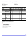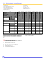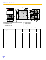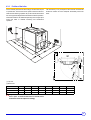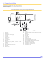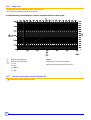
1
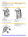
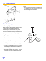
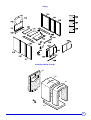
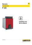
EN Fuel oil/gas boilers GT 430 Installation and Service Manual 300011893-001-02 Declaration of conformity CE The appliance complies with the standard model described in declaration of compliance 1. It is manufactured and distributed pursuant to the requirements of european directives. The original of the declaration of compliance is available from the manufacturer. C002721-A 2 GT 430 05/03/2013 - 300011893-001-02 Contents 1 Introduction . . . . . . . . . . . . . . . . . . . . . . . . . . . . . . . . . . . . . . . . . . . . . . . . . . . . . . . . . . . . . . . . . . . . . . . . . . . . .5 1.1 1.2 Symbols and abbreviations . . . . . . . . . . . . . . . . . . . . . . . . . . . . . . . . . . . . . . . . . . . . . . . . . . . . . . . . . . . . . . . . . . . . . . . . . . . . . . . .5 General. . . . . . . . . . . . . . . . . . . . . . . . . . . . . . . . . . . . . . . . . . . . . . . . . . . . . . . . . . . . . . . . . . . . . . . . . . . . . . . . . . . . . . . . . . . . . . . .5 1.2.1 Manufacturer's liability . . . . . . . . . . . . . . . . . . . . . . . . . . . . . . . . . . . . . . . . . . . . . . . . . . . . . . . . . . . . . . . . . . . . . . . . . . . . . .5 1.2.2 Installer's liability . . . . . . . . . . . . . . . . . . . . . . . . . . . . . . . . . . . . . . . . . . . . . . . . . . . . . . . . . . . . . . . . . . . . . . . . . . . . . . . . . .5 1.3 User's liability . . . . . . . . . . . . . . . . . . . . . . . . . . . . . . . . . . . . . . . . . . . . . . . . . . . . . . . . . . . . . . . . . . . . . . . . . . . . . . . . . . . . .6 1.4 Homologations . . . . . . . . . . . . . . . . . . . . . . . . . . . . . . . . . . . . . . . . . . . . . . . . . . . . . . . . . . . . . . . . . . . . . . . . . . . . . . . . . . . . . . . . . .6 1.4.1 Certifications . . . . . . . . . . . . . . . . . . . . . . . . . . . . . . . . . . . . . . . . . . . . . . . . . . . . . . . . . . . . . . . . . . . . . . . . . . . . . . . . . . . . .6 1.4.2 Directive 97/23/EC . . . . . . . . . . . . . . . . . . . . . . . . . . . . . . . . . . . . . . . . . . . . . . . . . . . . . . . . . . . . . . . . . . . . . . . . . . . . . . . . .6 2 Safety instructions and recommendations. . . . . . . . . . . . . . . . . . . . . . . . . . . . . . . . . . . . . . . . . . . . . . . . . . . .7 2.1 Safety instructions . . . . . . . . . . . . . . . . . . . . . . . . . . . . . . . . . . . . . . . . . . . . . . . . . . . . . . . . . . . . . . . . . . . . . . . . . . . . . . . . . . . . . . .7 2.1.1 Fire hazard . . . . . . . . . . . . . . . . . . . . . . . . . . . . . . . . . . . . . . . . . . . . . . . . . . . . . . . . . . . . . . . . . . . . . . . . . . . . . . . . . . . . . . .7 2.1.2 Risk of intoxication . . . . . . . . . . . . . . . . . . . . . . . . . . . . . . . . . . . . . . . . . . . . . . . . . . . . . . . . . . . . . . . . . . . . . . . . . . . . . . . . .7 2.1.3 Risk of being burnt . . . . . . . . . . . . . . . . . . . . . . . . . . . . . . . . . . . . . . . . . . . . . . . . . . . . . . . . . . . . . . . . . . . . . . . . . . . . . . . . .7 2.1.4 Risk of damage . . . . . . . . . . . . . . . . . . . . . . . . . . . . . . . . . . . . . . . . . . . . . . . . . . . . . . . . . . . . . . . . . . . . . . . . . . . . . . . . . . .7 2.2 Recommendations . . . . . . . . . . . . . . . . . . . . . . . . . . . . . . . . . . . . . . . . . . . . . . . . . . . . . . . . . . . . . . . . . . . . . . . . . . . . . . . . . . . . . . .7 3 Technical description . . . . . . . . . . . . . . . . . . . . . . . . . . . . . . . . . . . . . . . . . . . . . . . . . . . . . . . . . . . . . . . . . . . . .8 3.1 3.2 General description . . . . . . . . . . . . . . . . . . . . . . . . . . . . . . . . . . . . . . . . . . . . . . . . . . . . . . . . . . . . . . . . . . . . . . . . . . . . . . . . . . . . . .8 Composition of the range . . . . . . . . . . . . . . . . . . . . . . . . . . . . . . . . . . . . . . . . . . . . . . . . . . . . . . . . . . . . . . . . . . . . . . . . . . . . . . . . . .8 3.2.1 - S3 Standard control panel . . . . . . . . . . . . . . . . . . . . . . . . . . . . . . . . . . . . . . . . . . . . . . . . . . . . . . . . . . . . . . . . . . . . . . . . . .8 3.2.2 K3 control panel . . . . . . . . . . . . . . . . . . . . . . . . . . . . . . . . . . . . . . . . . . . . . . . . . . . . . . . . . . . . . . . . . . . . . . . . . . . . . . . . . . .8 3.2.3 DIEMATIC-m3 control panel . . . . . . . . . . . . . . . . . . . . . . . . . . . . . . . . . . . . . . . . . . . . . . . . . . . . . . . . . . . . . . . . . . . . . . . . .9 3.2.4 B3 control panel . . . . . . . . . . . . . . . . . . . . . . . . . . . . . . . . . . . . . . . . . . . . . . . . . . . . . . . . . . . . . . . . . . . . . . . . . . . . . . . . . . .9 3.3 Technical specifications . . . . . . . . . . . . . . . . . . . . . . . . . . . . . . . . . . . . . . . . . . . . . . . . . . . . . . . . . . . . . . . . . . . . . . . . . . . . . . . . . .10 3.3.1 Boilers for following countries: France, Belgium, Spain, Estonia, Luxemburg, Poland, Portugal, Czech Republic . . . . . . . . . . . . . . . . . 10 3.3.2 Boilers for following countries: Germany, Austria, Serbia, Slovenia . . . . . . . . . . . . . . . . . . . . . . . . . . . . . . . . . . . . . . . . . .11 3.3.3 Boilers for following countries: Switzerland . . . . . . . . . . . . . . . . . . . . . . . . . . . . . . . . . . . . . . . . . . . . . . . . . . . . . . . . . . . . .12 3.3.4 Boilers for following countries: Russia . . . . . . . . . . . . . . . . . . . . . . . . . . . . . . . . . . . . . . . . . . . . . . . . . . . . . . . . . . . . . . . . .13 3.3.5 Boilers for following countries: Algeria, Bulgaria, China, Cyprus, Denmark, Finland, Greece, Morocco, Norway, Romania, Sweden, Tunisia 14 4 Installation . . . . . . . . . . . . . . . . . . . . . . . . . . . . . . . . . . . . . . . . . . . . . . . . . . . . . . . . . . . . . . . . . . . . . . . . . . . . .15 4.1 Regulations governing installation . . . . . . . . . . . . . . . . . . . . . . . . . . . . . . . . . . . . . . . . . . . . . . . . . . . . . . . . . . . . . . . . . . . . . . . . . .15 4.1.1 In particular for France . . . . . . . . . . . . . . . . . . . . . . . . . . . . . . . . . . . . . . . . . . . . . . . . . . . . . . . . . . . . . . . . . . . . . . . . . . . . .15 4.1.2 In particular for Germany . . . . . . . . . . . . . . . . . . . . . . . . . . . . . . . . . . . . . . . . . . . . . . . . . . . . . . . . . . . . . . . . . . . . . . . . . . .15 4.2 Package list . . . . . . . . . . . . . . . . . . . . . . . . . . . . . . . . . . . . . . . . . . . . . . . . . . . . . . . . . . . . . . . . . . . . . . . . . . . . . . . . . . . . . . . . . . .15 4.3 Choice of the location . . . . . . . . . . . . . . . . . . . . . . . . . . . . . . . . . . . . . . . . . . . . . . . . . . . . . . . . . . . . . . . . . . . . . . . . . . . . . . . . . . . .16 4.3.1 Main dimensions . . . . . . . . . . . . . . . . . . . . . . . . . . . . . . . . . . . . . . . . . . . . . . . . . . . . . . . . . . . . . . . . . . . . . . . . . . . . . . . . .16 4.3.2 Position of the boiler. . . . . . . . . . . . . . . . . . . . . . . . . . . . . . . . . . . . . . . . . . . . . . . . . . . . . . . . . . . . . . . . . . . . . . . . . . . . . . .17 4.3.3 Ventilation . . . . . . . . . . . . . . . . . . . . . . . . . . . . . . . . . . . . . . . . . . . . . . . . . . . . . . . . . . . . . . . . . . . . . . . . . . . . . . . . . . . . . .18 4.4 Example of an installation. . . . . . . . . . . . . . . . . . . . . . . . . . . . . . . . . . . . . . . . . . . . . . . . . . . . . . . . . . . . . . . . . . . . . . . . . . . . . . . . .19 4.5 Hydraulic connections . . . . . . . . . . . . . . . . . . . . . . . . . . . . . . . . . . . . . . . . . . . . . . . . . . . . . . . . . . . . . . . . . . . . . . . . . . . . . . . . . . .20 4.5.1 Flushing the system . . . . . . . . . . . . . . . . . . . . . . . . . . . . . . . . . . . . . . . . . . . . . . . . . . . . . . . . . . . . . . . . . . . . . . . . . . . . . . .20 4.5.2 Sludge removal . . . . . . . . . . . . . . . . . . . . . . . . . . . . . . . . . . . . . . . . . . . . . . . . . . . . . . . . . . . . . . . . . . . . . . . . . . . . . . . . . .20 4.5.3 Hydraulic connection of the heating circuit. . . . . . . . . . . . . . . . . . . . . . . . . . . . . . . . . . . . . . . . . . . . . . . . . . . . . . . . . . . . . .21 4.5.4 Safety valve . . . . . . . . . . . . . . . . . . . . . . . . . . . . . . . . . . . . . . . . . . . . . . . . . . . . . . . . . . . . . . . . . . . . . . . . . . . . . . . . . . . . .22 4.5.5 Connection of the water circuit for domestic use . . . . . . . . . . . . . . . . . . . . . . . . . . . . . . . . . . . . . . . . . . . . . . . . . . . . . . . . .22 4.6 Chimney connection . . . . . . . . . . . . . . . . . . . . . . . . . . . . . . . . . . . . . . . . . . . . . . . . . . . . . . . . . . . . . . . . . . . . . . . . . . . . . . . . . . . . .23 4.6.1 Flue size. . . . . . . . . . . . . . . . . . . . . . . . . . . . . . . . . . . . . . . . . . . . . . . . . . . . . . . . . . . . . . . . . . . . . . . . . . . . . . . . . . . . . . . .23 4.6.2 Connection to the flue gas pipe . . . . . . . . . . . . . . . . . . . . . . . . . . . . . . . . . . . . . . . . . . . . . . . . . . . . . . . . . . . . . . . . . . . . . .23 4.7 Fuel-oil or gas connections. . . . . . . . . . . . . . . . . . . . . . . . . . . . . . . . . . . . . . . . . . . . . . . . . . . . . . . . . . . . . . . . . . . . . . . . . . . . . . . .24 4.8 Electrical connections. . . . . . . . . . . . . . . . . . . . . . . . . . . . . . . . . . . . . . . . . . . . . . . . . . . . . . . . . . . . . . . . . . . . . . . . . . . . . . . . . . . .24 4.9 Filling the system . . . . . . . . . . . . . . . . . . . . . . . . . . . . . . . . . . . . . . . . . . . . . . . . . . . . . . . . . . . . . . . . . . . . . . . . . . . . . . . . . . . . . . .25 05/03/2013 - 300011893-001-02 GT 430 3 5 Commissioning . . . . . . . . . . . . . . . . . . . . . . . . . . . . . . . . . . . . . . . . . . . . . . . . . . . . . . . . . . . . . . . . . . . . . . . . .26 6 Switching off the boiler. . . . . . . . . . . . . . . . . . . . . . . . . . . . . . . . . . . . . . . . . . . . . . . . . . . . . . . . . . . . . . . . . . .26 6.1 6.2 7 Precautions required in the case of long boiler stops. . . . . . . . . . . . . . . . . . . . . . . . . . . . . . . . . . . . . . . . . . . . . . . . . . . . . . . . . . . .26 Precautions required if the heating is stopped when there is a risk of freezing . . . . . . . . . . . . . . . . . . . . . . . . . . . . . . . . . . . . . . . .26 Checking and maintenance . . . . . . . . . . . . . . . . . . . . . . . . . . . . . . . . . . . . . . . . . . . . . . . . . . . . . . . . . . . . . . .27 7.1 System maintenance . . . . . . . . . . . . . . . . . . . . . . . . . . . . . . . . . . . . . . . . . . . . . . . . . . . . . . . . . . . . . . . . . . . . . . . . . . . . . . . . . . . .27 7.1.1 Water level . . . . . . . . . . . . . . . . . . . . . . . . . . . . . . . . . . . . . . . . . . . . . . . . . . . . . . . . . . . . . . . . . . . . . . . . . . . . . . . . . . . . . .27 7.1.2 Draining . . . . . . . . . . . . . . . . . . . . . . . . . . . . . . . . . . . . . . . . . . . . . . . . . . . . . . . . . . . . . . . . . . . . . . . . . . . . . . . . . . . . . . . .27 7.2 Data plate . . . . . . . . . . . . . . . . . . . . . . . . . . . . . . . . . . . . . . . . . . . . . . . . . . . . . . . . . . . . . . . . . . . . . . . . . . . . . . . . . . . . . . . . . . . . .27 7.3 Maintenance . . . . . . . . . . . . . . . . . . . . . . . . . . . . . . . . . . . . . . . . . . . . . . . . . . . . . . . . . . . . . . . . . . . . . . . . . . . . . . . . . . . . . . . . . . .28 7.3.1 Cleaning the flue gas circuit . . . . . . . . . . . . . . . . . . . . . . . . . . . . . . . . . . . . . . . . . . . . . . . . . . . . . . . . . . . . . . . . . . . . . . . . .28 7.3.2 Cleaning the combustion chamber. . . . . . . . . . . . . . . . . . . . . . . . . . . . . . . . . . . . . . . . . . . . . . . . . . . . . . . . . . . . . . . . . . . .28 7.3.3 Positioning of the baffle plates . . . . . . . . . . . . . . . . . . . . . . . . . . . . . . . . . . . . . . . . . . . . . . . . . . . . . . . . . . . . . . . . . . . . . . .29 7.3.4 Cleaning the flue gas box. . . . . . . . . . . . . . . . . . . . . . . . . . . . . . . . . . . . . . . . . . . . . . . . . . . . . . . . . . . . . . . . . . . . . . . . . . .30 7.3.5 Chemical sweeping . . . . . . . . . . . . . . . . . . . . . . . . . . . . . . . . . . . . . . . . . . . . . . . . . . . . . . . . . . . . . . . . . . . . . . . . . . . . . . .30 7.4 Cleaning the casing material . . . . . . . . . . . . . . . . . . . . . . . . . . . . . . . . . . . . . . . . . . . . . . . . . . . . . . . . . . . . . . . . . . . . . . . . . . . . . .31 7.5 Maintenance of the burner . . . . . . . . . . . . . . . . . . . . . . . . . . . . . . . . . . . . . . . . . . . . . . . . . . . . . . . . . . . . . . . . . . . . . . . . . . . . . . . .31 8 4 Spare parts - GT 430 . . . . . . . . . . . . . . . . . . . . . . . . . . . . . . . . . . . . . . . . . . . . . . . . . . . . . . . . . . . . . . . . . . . . .32 GT 430 05/03/2013 - 300011893-001-02 1 Introduction 1.1 Symbols and abbreviations Caution danger Reference Risk ZRefer of injury and damage to equipment. Attention must be to another manual or other pages in this instruction paid to the warnings on safety of persons and equipment. manual. DHW: Domestic hot water Specific information Information must be kept in mind to maintain comfort. 1.2 General 1.2.1 Manufacturer's liability Our products are manufactured in compliance with the requirements of the various applicable European Directives. They are therefore delivered with 1 marking and all relevant documentation. In the interest of customers, we are continuously endeavouring to make improvements in product quality. All the specifications stated in this document are therefore subject to change without notice. 1.2.2 Our liability as the manufacturer may not be invoked in the following cases: ` Failure to abide by the instructions on using the appliance. ` Faulty or insufficient maintenance of the appliance. ` Failure to abide by the instructions on installing the appliance. Installer's liability The installer is responsible for the installation and inital start up of the appliance. The installer must respect the following instructions: ` Read and follow the instructions given in the manuals provided with the appliance. ` Carry out installation in compliance with the prevailing legislation and standards. ` Perform the initial start up and carry out any checks necessary. ` Explain the installation to the user. ` If a maintenance is necessary, warn the user of the obligation to check the appliance and maintain it in good working order. ` Give all the instruction manuals to the user. 05/03/2013 - 300011893-001-02 GT 430 5 1.3 User's liability To ensure the optimum operation of your appliance, we strongly recommend that you abide by the following instructions: ` Read and follow the instructions given in the manuals provided with the appliance. ` Call on qualified professionals to carry out installation and initial start up. ` Get your installer to explain your installation to you. ` Have the required checks and services done. ` Keep the instruction manuals in good condition close to the appliance. This appliance is not intended to be used by persons (including children) whose physcial, sensory or mental capacity is impaired or persons with no experience or knowledge, unless they have the benefit, through the intermediary of a person responsible for their safety, of supervision or prior instructions regarding use of the appliance. Care should be taken to ensure that children do not play with the appliance. 1.4 Homologations 1.4.1 Certifications CE identification no: 1312 AQ 951 (Base): France, Germany, Austria, Belgium, Spain, Italy, Luxemburg, Poland, Portugal, Czech Republic, Slovenia, Switzerland. 1.4.2 CE identification no: 1312 AQ 952 (Export): Algeria, Bulgaria, China, Finland, Greece, Ireland, Jordan, Lebanon, Morocco, Norway, Romania, Russia, Syria, Tunisia, Turkey. Directive 97/23/EC Gas and oil boilers with a maximum operating temperature of 110°C and hot water tanks with a maximum operating pressure of 10 bar pertain to article 3.3 of the directive, and therefore, cannot be CEmarked to certify compliance with the directive 97/23 EC. The boilers and hot water tanks are designed and manufactured in accordance with the sound engineering practice, as requested in article 3.3 of the directive 97/23/EC, it is certified by compliance with the directives 90/396/EC, 92/42/EC, 2006/95/EC and 2004/108/EC. 6 GT 430 05/03/2013 - 300011893-001-02 2 Safety instructions and recommendations 2.1 Safety instructions For a proper operating of the boiler, follow carefully the Before any work, switch off the mains supply to the instructions. appliance. Only qualified professionals are authorised to work on the Keep to the polarity shown on the terminals: phase (L), appliance neutral and the installation. (N) and earth 4. Incorrect use or unauthorised modifications to the installation Keep children away from the boiler. or the equipment itself invalidate any right to claim. 2.1.1 Fire hazard to store inflammable products and materials inIt istheforbidden boiler room or close to the boiler, even temporarily. If you smell gas, do not use a naked flame, do not smoke, do not operate electrical contacts or switches (doorbell, lights, motor, lift, etc.): 2.1.2 Risk of intoxication Do not obstruct the air inlets in the room (even partially). If you smell flue gases: 2.1.3 1. Shut off the gas supply. 2. Open the windows. 3. Extinguish all flames. 4. Evacuate the premises. 5. Contact a qualified professional. 6. Inform the gas supplier. 1. Switch the appliance off. 2. Open the windows. 3. Evacuate the premises. 4. Contact a qualified professional. Risk of being burnt Depending on the settings of the appliance: - The temperature of the flue gas conduits may exceed 60°C. - The temperature of the radiators may reach 95°C. - The temperature of the domestic hot water may reach 65°C. 2.1.4 Risk of damage Do not stock chloride or fluoride compounds close to the Do not neglect to service the appliance: Contact a qualified appliance. professional or take out a maintenance contract for the annual servicing of the appliance. Install the appliance in frost-free premises. 2.2 Recommendations ` Check regularly that the installation contains water and is pressurised. ` Keep the appliance accessible at all times. ` Avoid draining the installation. ` The appliance should be on Summer or Antrifreeze mode rather than switched off to guarantee the following functions: - Anti blocking of pumps. - Antifreeze protection. - Protection against corrosion on domestic hot water tanks fitted with a titanium anode. 05/03/2013 - 300011893-001-02 GT 430 7 3 Technical description 3.1 General description The boilers of the GT 430 range are pressurised hot water boilers designed for connecting to a flue pipe which require a separate automatic fuel-oil or gas burner. GT 430 boilers have the following characteristics: - Heating body in cast iron. - S3, B3, K3 or DIEMATIC-m3 control panel. - Production of domestic hot water can be ensured by a separate hot water calorifier. 3.2 Composition of the range 3.2.1 - S3 Standard control panel Standard panel to be fitted Panel comprising the settings, control and safety devices allowing the boiler to operate autonomously, without regulation. 3.2.2 The standard panel is used to connect the boiler to the boiler room control cabinet. This cabinet can be fitted with control units. K3 control panel Separate panel Panel comprising the settings, control and safety devices allowing the boiler to operate autonomously. Side panel A version of the K3 control panel with lateral attachment is also available. Control panel K3 also allows the boiler to be used as a secondary boiler for installations with 2 to 10 boilers in cascade, one of which is fitted with a "DIEMATIC-m3" control panel. 8 GT 430 05/03/2013 - 300011893-001-02 3.2.3 DIEMATIC-m3 control panel Separate panel Top of the range electronic control panel with digital display, comprising the settings, control and safety devices allowing the boiler to operate autonomously. The DIEMATIC-m3 panel is fitted as standard with a control unit which operates according to the outside temperature. Side panel A version of the DIEMATIC-m3 control panel with lateral attachment is also available. The DIEMATIC-m3 panel also allows the boiler to be used as a master boiler for installations with 2 to 10 boilers in cascade. The other boilers (1 to 9) must be fitted with a "K3" control panel. 3.2.4 B3 control panel Separate panel Side panel Top of the range electronic control panel with digital display, comprising the settings, control and safety devices allowing the boiler to operate autonomously. A version of the B3 control panel with lateral attachment is also available. This panel makes it possible to give priority to DHW. 05/03/2013 - 300011893-001-02 GT 430 9 3.3 Technical specifications 3.3.1 Boilers for following countries: France, Belgium, Spain, Estonia, Luxemburg, Poland, Portugal, Czech Republic Conditions of use: Test conditions: Maximum operating temperature: 100 °C CO² Fuel oil = 13% Maximum operating pressure: 6 bar CO² Natural gas = 9.5% Thermostat adjustable from 30 to 90°C Ambient temperature: 20 °C Safety thermostat: 110 °C Boiler GT 430-8 GT 430-9 GT 430-10 GT 430-11 GT 430-12 GT 430-13 GT 430-14 Useful output kW 250-310 310-370 370-430 430-495 495-570 570-645 645-700 Power input kW 269-337 333-401 400-469 463-537 534-619 615-703 697-763 8 9 10 11 12 13 14 l 366 409 452 495 538 581 624 mbar 19 32 51 69 94 126 156 ∆ T = 15K 9 15 23 31 42 56 70 ∆ T = 20K 5 8 13 17 24 32 39 Number of sections Water content Water resistance ∆ T = 10K Pressure in the furnace for nozzle pressure =0 mbar 0.57 0.73 0.96 1.2 1.57 2.0 2.5 Smoke temperature (1) (3) °C 200 200 200 200 200 200 200 Kg/h 516 615 716 823 947 1071 1163 Gas 568 677 789 906 1043 1180 1280 Combustion chamber Diameter, mm combustion chamber 530 530 530 530 530 530 530 Mass flue gas flow rate (1) (2) Stand-by losses (4) Fuel oil Width, combustion chamber mm 638 638 638 638 638 638 638 Depth, combustion chamber mm 1183 1343 1503 1663 1823 1983 2143 Volume m3 0.310 0.354 0.396 0.439 0.481 0.523 0.565 ∆ T = 50K W 580 600 640 740 780 870 870 kg 1802 2072 2238 2454 2638 2880 3057 Net weight order for the boiler to operate correctly, it is imperative toIn respect the draught at the nozzle. (1) Nominal operation (top boiler power). (2) CO2 = 13% on fuel oil and 9.5% on natural gas. (3) Boiler temperature: 80 °C. Ambient temperature: 20 °C. (4) Stand-by losses in accordance with prevailing standard (EN 303/304). 10 1 mbar = 10 mmWG = 10 daPa GT 430 05/03/2013 - 300011893-001-02 3.3.2 Boilers for following countries: Germany, Austria, Serbia, Slovenia Conditions of use: Test conditions: Maximum operating temperature: 100 °C CO² Fuel oil = 13% Maximum operating pressure: 6 bar CO² Natural gas = 9.5% Thermostat adjustable from 30 to 90°C Ambient temperature: 20 °C Safety thermostat: 110 °C Boiler GT 430-8 GT 430-9 GT 410-10 GT 430-11 GT 430-12 GT 430-13 GT 430-14 Useful output kW 220-265 265-315 315-365 365-425 425-485 485-550 550-615 Power input kW 238-288 286-342 339-395 392-459 457-527 522-595 591-663 Number of sections Water content Water resistance ∆ T = 10K 8 9 10 11 12 13 14 l 366 409 452 495 538 581 624 mbar 14 24 37 51 68 92 121 4 6 9 13 17 23 30 0.4 0.55 0.68 0.9 1.1 1.5 1.8 ∆ T = 20K Pressure in the furnace for nozzle pressure =0 mbar Smoke temperature (1) (3) °C 180 180 180 180 180 180 180 Kg/h 450 530 610 710 810 910 1020 Gas 470 555 640 745 850 955 1070 Combustion chamber Diameter, mm combustion chamber 530 530 530 530 530 530 530 638 638 638 638 638 638 638 1183 1343 1503 1663 1823 1983 2143 0.310 0.354 0.396 0.439 0.481 0.523 0.565 0.17 0.15 0.14 0.12 0.11 0.11 0.10 1802 2072 2238 2454 2638 2880 3057 Mass flue gas flow rate (1) (2) Maintenance consumption* (3) Fuel oil Width, combustion chamber mm Depth, combustion chamber mm Volume m3 ∆ T = 50K % Net weight kg *Maintenance consumption: total heat emission when the burner is off as a percentage of the nominal input power when the difference between the mean boiler temperature and the room temperature is 50K. 1 mbar = 10 mmWG = 10 daPa order for the boiler to operate correctly, it is imperative toIn respect the draught at the nozzle. (1) Nominal operation (top boiler power). (2) CO2 = 13% on fuel oil and 9.5% on natural gas. (3) Ambient temperature: 20 °C. 05/03/2013 - 300011893-001-02 GT 430 11 3.3.3 Boilers for following countries: Switzerland Conditions of use: Test conditions: Maximum operating temperature: 100 °C CO² Fuel oil = 13% Maximum operating pressure: 6 bar CO² Natural gas = 9.5% Thermostat adjustable from 30 to 90°C Ambient temperature: 20 °C Safety thermostat: 110 °C Boiler GT 430-8 GT 430-9 GT 410-10 GT 430-11 GT 430-12 GT 430-13 GT 430-14 Useful output kW 180-224 212-264 252-312 305-400 365-470 425-530 475-580 Power input kW 194-242 227-285 271-337 327-431 391-507 455-572 508-625 Number of sections Water content Water resistance (1) ∆ T = 10K 8 9 10 11 12 13 14 l 366 409 452 495 538 581 624 mbar 10 17 27 45 64 85 107 5 8 12 20 28 38 48 3 4 7 12 16 21 27 0.3 0.45 0.6 0.8 1.1 1.3 1.5 160 160 160 170 170 170 170 373 439 520 665 781 880 963 410 483 572 732 860 969 1061 530 530 530 530 530 530 530 ∆ T = 15K ∆ T = 20K Pressure in the furnace for nozzle pressure = 0 (1) mbar Smoke temperature (1) (3) °C Mass flue gas flow rate (1) (2) (4) Fuel oil Gas Kg/h Combustion chamber Diameter, mm combustion chamber Maintenance consumption* Width, combustion chamber mm 638 638 638 638 638 638 638 Depth, combustion chamber mm 1183 1343 1503 1663 1823 1983 2143 Volume m3 0.310 0.354 0.396 0.439 0.481 0.523 0.565 ∆ T = 50K % 0.2 0.17 0.16 0.12 0.11 0.11 0.10 1802 2072 2238 2454 2638 2880 3057 Net weight kg *Maintenance consumption: total heat emission when the burner is off as a percentage of the nominal input power when the difference between the mean boiler temperature and the room temperature is 50K. 1 mbar = 10 mmWG = 10 daPa order for the boiler to operate correctly, it is imperative toIn respect the draught at the nozzle. (1) Nominal operation (top boiler power). (2) CO2 = 13% on fuel oil and 9% on natural gas. (3) Ambient temperature: 20 °C. (4) in accordance with DIN 4705 Teil 1. 12 GT 430 05/03/2013 - 300011893-001-02 3.3.4 Boilers for following countries: Russia Conditions of use: Test conditions: Maximum operating temperature: 100 °C CO² Fuel oil = 13% Maximum operating pressure: 6 bar CO² Natural gas = 9.5% Thermostat adjustable from 30 to 90°C Ambient temperature: 20 °C Safety thermostat: 110 °C GT 430-8 GT 430-9 GT 410-10 GT 430-11 GT 430-12 GT 430-13 GT 430-14 Useful output Boiler kW 300-357 357-419 419-481 481-543 543-605 605-667 667-729 Power input kW 329-394 392-462 460-530 526-597 595-666 659-731 727-798 8 9 10 11 12 13 14 366 409 452 495 538 581 624 25 42 63 83 106 135 169 11 18 28 37 47 60 75 6 10 16 21 26 34 42 0.92 1.30 1.59 2.05 2.04 2.15 3.06 <190 <190 <190 <190 <190 <190 <190 600 710 810 910 1020 1120 1220 630 740 850 960 1070 1170 1280 530 530 530 530 530 530 530 Number of sections Water content Water resistance (1) l ∆ T = 10K ∆ T = 15K mbar ∆ T = 20K Pressure in the furnace for nozzle pressure = 0 (1) Smoke temperature - Ambient temperature(1) (3) Mass flue gas flow rate (1) (2) Fuel oil Gas mbar K Kg/h Combustion chamber Diameter, mm combustion chamber Stand-by losses (3) Width, combustion chamber mm 638 638 638 638 638 638 638 Depth, combustion chamber mm 1183 1343 1503 1663 1823 1983 2143 Volume m3 0.310 0.354 0.396 0.439 0.481 0.523 0.565 ∆ T = 50K W 315 358 413 451 494 505 555 kg 1802 2072 2238 2454 2638 2880 3057 Net weight order for the boiler to operate correctly, it is imperative toIn respect the draught at the nozzle. (1) Nominal operation (top boiler power). (2) CO2 = 13% on fuel oil and 9.5% on natural gas. (3) Ambient temperature: 20 °C. 05/03/2013 - 300011893-001-02 GT 430 1 mbar = 10 mmWG = 10 daPa 13 3.3.5 Boilers for following countries: Algeria, Bulgaria, China, Cyprus, Denmark, Finland, Greece, Morocco, Norway, Romania, Sweden, Tunisia Conditions of use: Test conditions: Maximum operating temperature: 100 °C CO² Fuel oil = 13% Maximum operating pressure: 6 bar CO² Natural gas = 9.5% Thermostat adjustable from 30 to 90°C Ambient temperature: 20 °C Safety thermostat: 110 °C Boiler GT 430-8 GT 430-9 GT 410-10 GT 430-11 GT 430-12 GT 430-13 GT 430-14 Useful output kW 300-390 390-450 450-540 540-600 600-670 670-720 720-780 Power input kW 329-434 429-502 495-599 594-670 661-751 737-804 789-871 Number of sections Water content Water resistance (1) l ∆ T = 10K mbar ∆ T = 15K ∆ T = 20K Pressure in the furnace for nozzle pressure = 0 (1) mbar Smoke temperature (1) (3) °C Mass flue gas flow rate (1) (2) Fuel oil Gas Kg/h Combustion chamber Diameter, mm combustion chamber Stand-by losses (3) 8 9 10 11 12 13 14 366 409 452 495 538 581 624 31 48 80 101 130 158 194 14 21 36 45 58 70 87 8 12 20 25 33 40 49 1.1 1.5 2.0 2.5 2.5 2.5 3.5 220 220 220 220 220 220 220 650 750 900 1000 1116 1200 1450 700 810 972 1080 1207 1297 1405 530 530 530 530 530 530 530 Width, combustion chamber mm 638 638 638 638 638 638 638 Depth, combustion chamber mm 1183 1343 1503 1663 1823 1983 2143 Volume m3 0.310 0.354 0.396 0.439 0.481 0.523 0.565 ∆ T = 50K W 315 358 413 451 494 505 555 kg 1802 2072 2238 2454 2638 2880 3057 Net weight order for the boiler to operate correctly, it is imperative toIn respect the draught at the nozzle. (1) Nominal operation (top boiler power). (2) CO2 = 13% on fuel oil and 9.5% on natural gas. (3) Ambient temperature: 20 °C. 14 GT 430 1 mbar = 10 mmWG = 10 daPa 05/03/2013 - 300011893-001-02 4 Installation 4.1 Regulations governing installation must be carried out in accordance with the prevailing regulations, the codes of practice and the recommendations inInstallation these instructions. 4.1.1 In particular for France Establishments open to the public Heating installations must be designed and constructed in such a way as to prevent the return of water from the heating circuit and products put into it into the drinking water network located upstream. The installation must not be in direct relation with the drinking water network (Article 16-7 of the departmental health Directive). Statutory terms and conditions of installation: When these installations are fitted with a filling system connected to the drinking water network, they comprise a CB disconnector (disconnector for zones with non-controllable pressure differences) which satisfy the functional requirements of the NF P 43-011 standard. - Safety regulations against fire and panic in establishments open to the public: The installation and maintenance of the appliance must be carried out in compliance with the statutory texts and rules of the codes of conduct in force, particularly: a. General regulations For all appliances: Residential buildings Statutory terms and conditions of installation and maintenance: - Articles GZ - Installations operating on combustible gases and liquefied hydrocarbons. The installation and maintenance of the appliance must be carried out by a qualified professional in compliance with the statutory texts of the codes of conduct in force, particularly: Then, depending on use: - Order of 27 April 2009 amending the Order of 2 August 1977 Technical and safety rules applicable to combustible gas and liquefied hydrocarbon installations situated inside residential buildings and their annexes. b. Instructions specific to each type of establishment open to the public (hospitals, stores, etc.). - NF P 45-204 standards Gas installation, (formerly DTU 61-1, gas installations: April 1982, addendum no 1: July 1984). - Local Sanitary Regulations For appliances connected to the electricity network: - NF C 15-100 standards Low voltage electrical installation - Rules.. 4.1.2 - Articles CH-Heating, ventilation, refrigeration, air conditioning and production of steam and domestic hot water. Certificate of compliance (only concerns GT 430 boilers fitted with a gas burner) In application of Article 25 of the Order of 27 April 2009 amending the Order of 2 August 1977 amended and Article 1 of the amended Order of 05/02/1999, the installer is required to draw up certificates of conformity approved by the Ministers responsible for construction and gas safety: - Different forms (forms 1, 2 or 3) for a new gas installation - Model 4 in particular after replacing a furnace with a new one. In particular for Germany Abide by the following standards, rules and directives when installing and commissioning the boiler: - DIN 4705: calculation of chimney dimensions. - DIN EN 12828 (June 2003 edition): heating systems in buildings. Planning of hot water heating installations (up to a maximum operating temperature of 105°C and a maximum output of 1 MW). - DIN 4753: drinking and industrial water heating installations. - DIN 1988: technical rules on drinking water installations (TRW). - DVGW-TRGI: technical rules on gas installations, including complementary equipment. - Working paper DVGW G 260/I: technical rules on the nature of the gas. 4.2 Package list ZSee assembly instructions. 05/03/2013 - 300011893-001-02 GT 430 15 4.3 Choice of the location 4.3.1 Main dimensions (1) The lateral control panel can be mounted to the right or left of the boiler. Exact height positioning defined by the fitter during assembly. Mk Tapped connection (2) Inscribed diameter (in mm): Heating flow - weld - Front section: 455 - Intermediate section: 530 Heating return - weld Rp 2" draining outlet Equivalent diameter (in mm): 573 Sludge removal hole Rp 2" 1/2 - plugged Boiler type øA (exterior) ø GT 430-8 GT 430-9 GT 410-10 GT 430-11 GT 430-12 GT 430-13 GT 430-14 250 250 250 300 300 300 300 2" 1/2 2" 1/2 2" 1/2 3" 3" 3" 3" 235 235 øC plate intact or pre-drilled to the diameter specified on order D 254 254 254 254 E 1427 1427 1427 1447 1447 1447 1447 J 1800 1950 2120 2305 2465 2625 2785 L 1505 1665 1825 1985 2145 2305 2465 S 1183 1343 1503 1663 1823 1983 2143 113.5 113.5 113.5 113.5 113.5 113.5 113.5 355 355 355 355 355 355 355 Control panels B3, K3 F and DIEMATIC-m3 G Standard panel - S3 16 235 H 190 190 190 190 190 190 190 K 1690 1690 1690 1690 1690 1690 1690 M 755 755 755 755 755 755 755 F 127.5 127.5 127.5 127.5 127.5 127.5 127.5 G 130 130 130 130 130 130 130 H 105 105 105 105 105 105 105 K 1605 1605 1605 1605 1605 1605 1605 M 738 738 738 738 738 738 738 GT 430 05/03/2013 - 300011893-001-02 4.3.2 Position of the boiler For the assembly and because of their design, GT 430 boilers require no special base. Their closed furnace system means that the floor need not have refractory properties. All you have to ensure is that the floor can support the weight of the boiler when it is fitted for operation. The dimensions (in mm) correspond to the minimum recommended dimensions needed to ensure adequate accessibility around the boiler. C000990-A If the boiler location is not determined precisely, leave enough space around the boiler to facilitate monitoring and maintenance operations. (1) Top view (2) Burner door GT 430-8 GT 430-9 GT 430-10 GT 430-11 GT 430-12 GT 430-13 GT 430-14 1505 1665 1825 1985 2145 2305 2465 A mm B mm 130 -40 120 -40 120 -40 120 C mm 1500 2000 2000 2000 2500 2500 2500 * Pay attention to the overall volume of the burner when the door is open. To install several boilers in cascade, these dimensions should be adapted accordingly. 05/03/2013 - 300011893-001-02 GT 430 17 4.3.3 Ventilation To allow the input of combustive air, sufficient ventilation must be provided in the boiler room, for which the cross section and emplacement must satisfy regulations in force in the country in which the boiler is installed. These compounds are present, for example, in aerosol sprays, paints, solvents, cleaning products, washing products, detergents, glues, snow clearing salts, etc. Position the air inlets in relation to the high ventilation vents in order that the air is refreshed throughout the boiler room. • Therefore: Do not obstruct the air inlets in the room (even partially). In order to avoid damage to the boiler, it is necessary to prevent the contamination of combustion air by chlorine and/or fluoride compounds, which are particularly corrosive. • Do not pull in air evacuated from premises using such products: hairdressing salons, dry cleaners, industrial premises (solvents), premises containing refrigeration systems (risk of refrigerant leakage), etc. Do not stock such products close to the boilers. If the boiler and/or peripheral equipment are corroded by such chloride or fluoride compounds, the contractual guarantee cannot be applied. France The minimum cross sections and the emplacement of the fresh air inlet and the air discharge are governed by the order of 21/03/1968 amended by the orders of 26/02/1974 and 03/03/1976. ` Generator installed in a building for collective use (installations less than 70 kW) The fresh air inlet must: - Come out in the lower section of the premises, - Have a free minimum cross section calculated on the basis of 0.03 dm² per kilowatt installed output and at least equal to 2.5 dm². ` The air discharge must: - Be located in the upper section of the premises, - Rise above the roof (unless using an equivalent system which does not cause a nuisance to neighbours), - Have a free cross section (corresponding to 2/3 of that of the air inlet and at least equal to 2.5 dm²). Generator installed in a builing for individual use ` An adequate supply of fresh air must be provided as close as possible to the appliances. Its cross section must be at least 0.5 dm². ` In the upper section of the premises, an air outlet must ensure effective ventilation. Establishments open to the public ` New establishment: Refer to the order of 25/06/1980 (installations of more than 20 kW and less than or equal to 70 kW). ` Existing establishment: Refer to the order of 25/06/1980 (installations less than 70 kW). 18 GT 430 05/03/2013 - 300011893-001-02 4.4 Example of an installation The example of an installation shown below does not cover every possible configuration. Its sole aim is to draw your attention to the basic rules to be respected. GT 430 boiler with domestic hot water production using an independent tank. 3 7 5 10 9 15 9 9 14 9 27 11 16 13 20 9 2 17 57 9 27 19 12 9 17 9 1 6 9 9 9 56 7 9 26 18 32 27 9 31 29 9 17 28 30 1 Heating flow 2 Heating return 3 3-bar safety valve + Pressure gauge 5 Flow switch 6 Air separator 7 Automatic air vent 9 Isolating valve 10 3-way mixing valve 11 Boiler pump 12 Sludge decanting pot (particularly recommended on older installations) 13 Flush valve 14 Water low safety pressure-sensitive switch 15 Shunt pump 16 Expansion vessel 05/03/2013 - 300011893-001-02 GT 430 8219N008C 17 Drain cock 18 Heating circuit filling (with disconnector depending on prevailing regulations) 19 Water treatment 20 Water meter 26 DHW load pump 27 Non-return valve 28 Domestic cold water inlet 29 Pressure reducer (if mains pressure > 5.5 bar) 30 Safety unit calibrated to 7 bar with indicator type discharge 31 Independent domestic hot water tanks 32 Domestic hot water loop pump (optional) 56 Domestic hot water circulation loop return 57 Domestic hot water outlet 19 4.5 Hydraulic connections 4.5.1 Flushing the system Installing the boiler in new installations (installations less than 6 months old) ` ` Clean the installation with a universal cleaner to eliminate debris from the appliance (copper, hemp, flux). ` Thoroughly flush the installation until the water runs clear and shows no impurities. 4.5.2 Remove sludge from the installation. ZSee: Sludge removal. ` Flush the installation. ` Clean the installation with a universal cleaner to eliminate debris from the appliance (copper, hemp, flux). ` Thoroughly flush the installation until the water runs clear and shows no impurities. Sludge removal A tapped ø 2’’ 1/2 hole with a plug has been provided on the bottom of the front of the boiler.. Fit a 1/4 turn valve (not supplied) on the opening to remove the sludge. After this operation, go ahead and fill the installation. ZSee: Remplissage de l’installation. Sludge removal leads to the draining of large quantities of water, so remember to refill the system after the operation. 20 Installing the boiler in existing installations GT 430 never replace a boiler in an existing system without carefully rinsing the system first. Install a sludge decanting pot on the return pipe, very close to the boiler. 05/03/2013 - 300011893-001-02 4.5.3 Hydraulic connection of the heating circuit Water flow in the boiler The water flow in the boiler when the burner is operating must correspond with the following formulae: - Nominal water flow Qn = 0.86 Pn/20. - Minimum flow Qmin = 0.86 Pn/45 (this flow also corresponds with the minimum recycle flow in the boiler). - Maximum water flow Qmax = 0.86 Pn/5. Qn = flow in m3/h. Pn = Nominal output (full boiler output) in kW. Operation in cascade After stopping the burner: - Timeout required before the order to close a 2 way valve: 3 min. - Switch a possible shunt pump (located between the boiler and a butterfly valve) off via the end of run contact of the butterfly valve. Operation with 2-stage burner - The water temperature in the boiler is maintained at 50°C or more; The first stage must be set to a minimum of 30% of the nominal stage. - Operation at modulated low temperature (minimum outlet temperature: 40°C); The first stage must be set to a minimum of 50% of the nominal stage. Operation with modulating burner - The water temperature in the boiler is maintained at 50°C or more: The burner can modulate down to 30% of the nominal stage. - Operation at modulated low temperature (minimum outlet temperature: 40°C); The burner can modulate down to 50% of the nominal stage. 05/03/2013 - 300011893-001-02 GT 430 21 4.5.4 Safety valve The safety valve must be connected to the boiler outlet and no other valve or flap must be interposed between it and the boiler. Minimum safety valve flowrate as a function of maximum boiler nominal output Minimum relieving capacity Maximum gross boiler output Unit (a) = kW Example Maximum boiler nominal output is 200 kW. Minimum safety valve flowrate must be 700 kg/h. (b) = lb/h (c) = MBtu/h (d) = Kg/h 4.5.5 Connection of the water circuit for domestic use ZSee: Domestic hot water calorifier instructions. 22 GT 430 05/03/2013 - 300011893-001-02 4.6 Chimney connection The high-performance features of modern boilers and their use in specific conditions as a result of the advance in burner technology (e.g. first-stage or low modulation range operation) lead to very low flue gas temperatures (<160°C). For this reason: - Use flue gas pipes designed to enable the flow of condensates which may result from such operating modes in order to prevent damage to the chimney. - Install a draining tee at the bottom of the chimney. The use of a draught moderator is recommended as well. 4.6.1 Flue size Refer to applicable regulations while determining the size of the flue. Please note that GT 430 boilers have pressurised and tight furnaces and that the pressure at the connection to the chimney must not exceed 0 mbar, unless special sealing precautions have been taken, for instance in order to connect a static condenser/regenerator. 4.6.2 order for the boiler to operate correctly, it is imperative toIn respect the draught at the nozzle (= 0). Connection to the flue gas pipe The connection shall be removable, and offer minimum load losses, i.e. it must be as short as possible with no sudden change in section. Its diameter shall always be at least equal to that of the boiler outlet, i.e.: A: ø 250 mm: for 8 to 10 sections. A: ø 300 mm: for 11 to 14 sections. Fit a measuring point (Ø 10 mm hole) on the flue, in order to adjust the burner (combustion check). 05/03/2013 - 300011893-001-02 GT 430 23 4.7 Fuel-oil or gas connections ZRefer to the instructions supplied with the burner. head deflector must be flush with the insulation ofThetheburner burner door. E D 8229N007-B C: Furnace door insulation D, E: Pressure gauge measurement socket (1) Max attachment diameter: - Max øB = 290 mm - Max øB = 330 mm with 4 fastenings at 15° or 45° ØA 135 175 190 240 250 290 ØB 170 200 220 270 325 330 ØD 10 10 10 10 10 10 ØE 10 10 10 10 10 10 ØM 8 8 10 10 14 12 4.8 Electrical connections Refer to the connection instructions supplied with the control Zpanel.. 24 GT 430 05/03/2013 - 300011893-001-02 4.9 Filling the system Filling shall be performed with a low flow rate from a low point in the boiler room in order to ensure that all the air in the boiler is bled from the high point of the system. All the pumps must be stopped before filling (included shunt pump(s)). Do not add cold water suddenly into the boiler when it is hot. VERY IMPORTANT: Instructions for starting up the boiler for the first time after the system is fully or partly drained: If all the air is not bled naturally to an expansion vessel which opens out onto the air, the system must include manual bleeder valves, in addition to automatic bleeder valves with the capability to bleed the system by themselves when it is operating, the manual bleeder valves are used to bleed all the high points of the system and to make sure that the filled system is free of air before the burner is turned on. 05/03/2013 - 300011893-001-02 GT 430 25 5 Commissioning ZSee: - Control panel instructions. - Burner instructions. - Domestic hot water calorifier instructions. 6 Switching off the boiler ` Set the On/Off switch to O. ZSee: Control panel instructions. ` DIEMATIC-m3 control panel The panel must always be supplied with 230V voltage: Cut the gas supply to the boiler (if present). - to ensure the anti-grip of the heating pump, - to ensure Titan Active System® operation when a titanium anode is protecting the DHW tank. Use the mode: - summer to shut down the heating. - antifreeze to shut down the boiler if you are to be absent. 6.1 Precautions required in the case of long boiler stops - The boiler and the chimney must be swept carefully. - Close all the doors of the boiler to prevent air from circulating inside the boiler. - We advise removing the pipe which connects the boiler to the chimney and to close off the nozzle with a cover. 6.2 Precautions required if the heating is stopped when there is a risk of freezing We recommend the use of a correctly dosed antifreeze agent to prevent to the heating circuit from freezing. If this cannot be done, drain the system completely. 26 GT 430 05/03/2013 - 300011893-001-02 7 Checking and maintenance 7.1 System maintenance 7.1.1 Water level Regularly check the level of water in the system and top up if required, taking care that cold water is not added suddenly into the boiler when it is hot. This operation should be required only a few times in each heating season, with very low quantities of water; otherwise, look for the leak and repair it. The use of an automatic filling is strongly discouraged. 7.1.2 Draining We advise you against draining the system unless it is absolutely necessary. For example: Several months' absence with the risk of ice in the building. 7.2 Data plate Boiler type Manufacturing date Year of manufacture Week of manufacture Serial no. of the appliance C000996-B The rating plate fixed on the side of the boiler during installation is used to identify the boiler correctly and also provides the main specifications of the boiler. 05/03/2013 - 300011893-001-02 GT 430 27 7.3 Maintenance The boiler will only operate efficiently if the exchange The operations described below shall only be performed surfaces with are kept clean. the boiler and power supply off. The boiler should be cleaned as soon as required and as the chimney, at least once a year or more, depending upon applicable regulations and specific needs. C003592-A Cleaning the flue gas circuit C003591-A 7.3.1 - Remove the upper front panel. - Take off the lower panels. - Open the sweeping doors (upper doors) by unscrewing the 3 nuts using a 19 mm spanner. - Remove the baffle plates from the upper flue ways. 7.3.2 - Carefully sweep the flue ways with the brush supplied for that purpose. - Brush the baffle plates. - If possible, use a vacuum cleaner. - Replace the baffle plates. - Close the doors. Cleaning the combustion chamber - Unscrew the 4 closing nuts and open the furnace door. - Brush out the inside of the furnace. - Use a vacuum cleaner to remove any soot which has accumulated in the combustion chamber. - Close the door and replace the front panel. C003593-A 28 GT 430 05/03/2013 - 300011893-001-02 7.3.3 Positioning of the baffle plates - Put the baffle plates back in place and hook them into each other before engaging them fully in the flue way. - Close the sweeping doors. 8229-0010 8229-0022 C0 03 37 0-B Follow the order of assembly shown in the diagram. The 8-figure part number of the baffle plate is cast in the metal. Boilers for following countries: France, Germany, Austria, Belgium, Spain, Estonia, Luxemburg, Poland, Portugal, Czech Republic, Serbia, Slovenia, Switzerland Boiler GT 430-8 GT 430-9 - GT 430-10 GT 430-11 - GT 430-12 GT 430-13 - GT 430-14 2 x 8229-0010 First 2 x 8229-0010 then 1 x 8229-0022 3 x 8229-0010 Upper flue ways First 8229-0010 then 82290022 Central flue ways First 8229-0011 then 82290023 2 x 8229-0011 First 2 x 8229-0011 then 1 x 8229-0023 3 x 8229-0011 Lower flue ways First 8229-0012 then 82290024 2 x 8229-0012 First 2 x 8229-0012 then 1 x 8229-0024 3 x 8229-0012 Boilers for following countries: Algeria, Bulgaria, China, Cyprus, Denmark, Finland, Greece, Norway, Morocco, Romania, Russia, Sweden, Tunisia Boiler GT 430-8 GT 430-9 - GT 43010 GT 430-11 GT 430-12 GT 430-13 - GT 43014 Upper flue ways First 8229-0010 then 8229-0022 2 x 8229-0010 First 2 x 8229-0010 then First 2 x 8229-0010 then 1 x 8229-0022 1 x 8229-0022 3 x 8229-0010 Central flue ways First 8229-0011 then 8229-0023 2 x 8229-0011 First 2 x 8229-0011 then First 2 x 8229-0011 then 1 x 8229-0023 1 x 8229-0023 3 x 8229-0011 Lower flue ways First 8229-0012 then 8229-0024 2 x 8229-0012 First 2 x 8229-0012 then 1 x 8229-0024 2 x 8229-0012 05/03/2013 - 300011893-001-02 GT 430 2 x 8229-0012 29 7.3.4 Cleaning the flue gas box To do so: - Open the left and right cleaning hatches on the flue gas box (2 nuts H 12 + flat washers with a 19 mm spanner) and remove any soot which has accumulated using a vacuum cleaner. - Replace the cleaning hatches. 7.3.5 Chemical sweeping General principle Boilers are traidtionally swept mechanically. There are now chemical sweeping methods which facilitate this maintenance work. A chemical reagent is applied to the boiler's heating surfaces. After application, the reaction is completed by igniting the burner. The initial deposits are neutralised and pyrolised. The remaining pulverent residues are easy to remove by sweeping or vacuum cleaning. 8800N065 The products The product must be suitable for boilers with a cast iron body. Various manufacturers offer products in the form of a concentrated liquid or aerosol. The aerosols are packaged in 0.5 to 1 l spray cans for treating domestic boilers. Refer to the instructions supplied with the product. The liquid products are available in 1 to 50 l containers. These concentrated liquids are diluted before application with a spray. 8800N063 Sprays exist in various forms suitable for their intended use: - Low capacity (2 or 3 l) spray with built-in reservoir for small boilers and moderate frequency. Manual pressurisation of the reservoir. - 5 l spray with separate reservoir, nozzle and connecting tube. The nozzles enable easy application at the back of the combustion chamber. Manual pressurisation of the reservoir. - Motor-assisted pressurisation spray with reservoir, nozzle and connecting tube. These sprays are intended for intensive use. 30 GT 430 05/03/2013 - 300011893-001-02 Operational mode The operating mode mentioned corresponds to standard user situations. Refer to the manufacturer's instructions for specific advice on the product used. Application - Depending on the product, the boiler must be cold or heated. Refer to the instructions supplied with the product. - Direct application to the heating surfaces with aerosol sprays. - The concentrates are diluted in the proportions 1/5 to 1/20 (depending on the product and the condition of the boiler). - Application with the spray is done in the upper part of the boiler and on the walls of the combustion chamber. Surfaces are dampened but not washed. It is not necesaary to use the spray to get between the heating surfaces. - A volume of one litre of solution is generally used for 1 m2 of heating surface (domestic boiler), i.e. 0.05 to 0.2 l of concentrate. Cleaning - Remove the baffle plates. - Light sweeping will remove the pulverent residues remaining after combustion. The remaining pulverent residues are easy to remove by sweeping or vacuum cleaning. For certain products, brief application after cleaning has a preventive effect, limiting deposits on the heating surfaces. - Replace the baffle plates. - Close the door of the combustion chamber. - Service the burner. - Replace the front panel. Ignition The burner is ignited after allowing the product time to penetrate for 2 to 5 min. Refer to the instructions supplied with the product. 7.4 Cleaning the casing material Use a soapy solution and a sponge only. Rinse with clean water and dry with chamois leather or a soft cloth. 7.5 Maintenance of the burner ZRefer to the instructions supplied with the burner. 05/03/2013 - 300011893-001-02 GT 430 31 8 Spare parts - GT 430 To order a spare part, quote the reference number next to the part required. 300011893-002-B Boiler body + Miscellaneous DE DIETRICH THERMIQUE S.A.S. - Spare parts centre 4 rue d’Oberbronn - F-67110 REICHSHOFFEN - * +33 (0)3 88 80 26 50 - + +33 (0)3 88 80 26 98 cprdedietrichthermique.com Casing Insulating material for body 50 49 8229N011A 48 47 05/03/2013 - 300011893-001-02 GT 430 33 Control panels ZRefer to the Spare Parts list in the panel instructions. S3 control panel - Package MD4 K3 control panel Separate panel - Package MD2 Side panel - Package MD139 DIEMATIC-m3 control panel Separate panel - Package MD1 Side panel - Package MD138 B3 control panel Separate panel - Package MD3 34 Side panel - Package MD140 GT 430 05/03/2013 - 300011893-001-02 Markers Code no. Description Markers Code no. Description Boiler body + Accessories 21 9755-0259 Furnace door guard Base frame 22 9755-0260 Furnace door insulation 1 8229-8900 Complete frame 7-8 sections 23 8229-0204 Added hinge 1 8229-8901 Complete frame 9-10 sections 24 9756-0213 Hinge pin for combustion chamber door 1 8229-8902 Complete frame 11-12 sections 25 8229-0205 Hinge for combustion chamber door 1 8229-8903 Complete frame 13-14 sections 25.1 8229-8944 Hinge unit 2 8229-8940 Complete rear section 26 8229-0025 Ramp 3 8229-0029 Normal intermediate section 27 9757-0027 Inspection flange 4 8229-0030 Special intermediate section 27.1 8015-7700 Flame inspection window + gaskets 5 8229-8941 Complete front section 28 9501-0080 Flame inspection window gasket 6 8005-0200 Nipple 29 8229-8905 Complete sweeping door, right 6.1 9430-5027 Nipple greasing product 30 8229-8906 Complete sweeping door, left 7 8229-8919 Assembly rod 425 mm 31 9755-0256 Insulation, sweeping door 7 8229-8920 Assembly rod 620 mm 32 9755-0257 Inner protection, sweeping door 7 8229-8921 Assembly rod 784 mm 33 8229-0202 Hinge for sweeping door 8 9754-0120 Spring 34 9756-0214 Hinge pin for sweeping door 9 9752-5232 Mounting square 35 8229-8907 Complete flue gas box 10 9508-6032 Glass fibre cord ø 10 mm (metre) 36 8229-8908 Complete right-hand cleaning trap 10.1 9428-5095 Tube of silicon mastic 37 8229-8909 Complete left-hand cleaning trap 11 8229-8923 Water flow pipe + gasket, 7 to 10 sections 38 8229-8916 Flue gas nozzle Ø 250 - 7 to 10 sections 11 8229-8918 Water flow pipe + gasket, 11 to 14 sections 38 8229-8917 Flue gas nozzle Ø 250 - 11 to 14 sections 12 8104-8965 Return collector + seal, 7 to 10 sections 40 8229-0010 Upper baffle plate, width 190 mm 12.1 8229-8922 Return collector + seal, 11 to 14 sections 40.1 8229-0022 Additional upper baffle plate, width 190 mm 13 9501-4135 Gasket 162x120x4 41 8229-0011 Upper baffle plate, width 240 mm 14 8202-0028 2" 1/2 plug with 1/2" opening 41.1 8229-0023 Additional upper baffle plate, width 240 mm 15 8013-0028 Solid plug 2" 1/2 42 8229-0012 Lower baffle plate 16 8500-0027 Sensor tube 42.1 8229-0024 Additional lower baffle plate 17 9758-1286 Spring for sensor tube 18 8229-8911 Complete combustion chamber door, no opening 18 8229-8943 Complete 10 mm combustion chamber door with opening on request 18.1 9495-0050 Plug 1/4" 19 8229-0532 Plate for combustion chamber door, no opening 19 8229-0546 Plate for combustion chamber door with opening ø 135 19 8339-0508 19 Flow switch (France + Germany) 43 8802-4703 Flow controller GT 407 43 8802-4707 Flow controller GT 408 43 8802-4710 Flow controller GT 409 43 8802-4712 Flow controller GT 430-10 43 8802-4722 Flow controller GT 430-11 Plate for combustion chamber door with opening ø 175 43 8802-4725 Flow controller GT 412 43 8802-4727 Flow controller GT 413 8229-0531 Plate for combustion chamber door with opening ø 190 43 8802-4729 Flow controller GT 414 19 8229-0533 Plate for combustion chamber door with opening ø 240 19 8339-0509 Plate for combustion chamber door with opening ø 250 43 8802-4700 Flow controller GT 407 43 8802-4703 Flow controller GT 408 19 8229-0534 Plate for combustion chamber door with opening ø 290 43 8802-4704 Flow controller GT 409 8802-4707 Flow controller GT 430-10 8229-0548 Plate for combustion chamber door with opening on request 43 19 43 8802-4720 Flow controller GT 430-11 20 9755-0258 Height converter, insulation 43 8802-4722 Flow controller GT 412 05/03/2013 - 300011893-001-02 Flow switch (Switzerland) GT 430 35 Markers Code no. 43 8802-4724 43 8802-4725 43 36 Description Markers Code no. Description Flow controller GT 413 111 200007422 Complete front side panel, left Flow controller GT 414 112 200007896 Complete side panel, left, width 770 mm 112 200007894 Complete side panel, left, width 610 mm Flow switch (Export) 112 200007898 Complete side panel, left, width 930 mm 43 8802-4711 Flow controller GT 408 113 200007421 Complete front side panel, right 43 8802-4713 Flow controller GT 409 114 200007893 Complete side panel, right, width 610 mm 43 8802-4715 Flow controller GT 430-10 114 200007895 Complete side panel, right, width 770 mm 43 8802-4726 Flow controller GT 430-11 114 200007897 Complete side panel, right, width 930 mm 43 8802-4728 Flow controller GT 412 115 8229-8835 Complete upper rear panel, left 43 8802-4729 Flow controller GT 413-GT 414 116 8229-8836 Complete upper rear panel, right 44 8229-8936 Screws and accessories bag 117 8229-8012 Lower back panel 45 8229-8937 Variable screws and accessories bag 118 8229-8837 Complete upper cross-bar 46 8229-5500 Body screws packet 119 8229-8809 Complete front cover 120 9755-0187 Rubber profile for cable way Insulating material for body 121 8229-0515 Complete intermediate cover 47 8229-4010 Lower insulation, boiler body - 7 and 8 sections 122 8229-0518 Complete rear cover, width 170 mm 47 8229-4016 Lower insulation, boiler body - 9 and 10 sections 122 8229-0511 Complete rear cover, width 330 mm 47 8229-4034 Lower insulation, boiler body - 11 and 12 sections 122 8229-0514 Complete rear cover, width 490 mm 47 8229-4036 Lower insulation, boiler body - 13 and 14 sections 123 8229-8818 Complete cable way, left, GT 407 48 8229-4004 Front boiler body insulation, width 500 mm 123 8229-8819 Complete cable way, left, GT 408 49 8229-4015 Boiler body insulation, width 520 mm 123 8229-8820 Complete cable way, left, GT 409 49 8229-4018 Insulating material for body - Length 600 mm 123 8229-8821 Complete cable way, left, GT 430-10 49 8229-4009 Insulating material for body - Length 800 mm 123 8229-8822 Complete cable way, left, GT 430-11 49 8229-4012 Insulating material for body - Length 900 mm 123 8229-8823 Complete cable way, left, GT 412 50 8229-4005 Rear insulation 123 8229-8824 Complete cable way, left, GT 413 123 8229-8825 Complete cable way, left, GT 414 Miscellaneous 124 8229-8826 Complete cable way, right, GT 407 60 9750-5025 Brush 124 8229-8827 Complete cable way, right, GT 408 61 9750-5060 1300 mm brush rod 124 8229-8828 Complete cable way, right, GT 409 62 9750-5048 Extension for brush rod 650 mm 124 8229-8829 Complete cable way, right, GT 430-10 63 9434-5103 Retouching spray paint - White 124 8229-8830 Complete cable way, right, GT 430-11 63 9434-5102 Retouching spray paint - anthracite grey 124 8229-8831 Complete cable way, right, GT 412 124 8229-8832 Complete cable way, right, GT 413 Casing 124 8229-8833 Complete cable way, right, GT 414 100 200007578 Complete upper front panel 125 8229-5501 Additional lower rear panel 101 8229-1001 Complete lower front panel, right 126 8229-8933 Screw bag, common parts 102 8229-1003 Complete lower front panel, left 127 8229-8934 Screw bag, variable parts CS11 103 8229-1004 Panel for furnace door 128 8229-8935 Screw bag, variable parts CS13 104 8229-1005 Sludge removal cap 105 8229-8834 Complete front casing support 106 8229-0537 Lower front crosspiece 107 8229-8807 Upper casing support, left 108 8229-8808 Upper casing support, right 109 8229-8010 Lower casing support 110 200007889 Side panel, left or right, width 480 mm GT 430 05/03/2013 - 300011893-001-02 Warranty You have just purchased one of our appliances and we thank you for the trust you have placed in our products. Please note that your appliance will provide good service for a longer period of time if it is regularly checked and maintained. Your fitter and our customer support network are at your disposal at all times. Warranty terms Starting from the purchase date shown on the original fitter's invoice, your appliance has a contractual guarantee against any manufacturing defect. The length of the guarantee is mentioned in the price catalogue. The manufacturer is not liable for any improper use of the appliance or failure to maintain or install the unit correctly (the user shall take care to ensure that the system is installed by a qualified fitter). In particular, the manufacturer shall not be held responsible for any damage, loss or injury caused by installations which do not comply with the following: - applicable local laws and regulations - specific requirements relating to the installation, such as national and/or local regulations - the manufacturer's instructions, in particular those relating to the regular maintenance of the unit - the rules of the profession The warranty is limited to the exchange or repair of such parts as have been recognised to be faulty by our technical department and does not cover labour, travel and carriage costs. The warranty shall not apply to the replacement or repair of parts damaged by normal wear and tear, negligence, repairs by unqualified parties, faulty or insufficient monitoring and maintenance, faulty power supply or the use of unsuitable fuel. Sub-assemblies such as motors, pumps, electric valves etc. are guaranteed only if they have never been dismantled. Italy The duration of our warranty is shown on the certificate delivered with the appliance. Our liability as manufacturer may not be invoked in respect of incorrect use of the appliance, incorrect or insufficient maintenance thereof, or incorrect installation of the appliance (you must therefore ensure that installation and maintenance operations are carried out respectively by a qualified professional and by an after sales service company). The legislation laid down by European Directive 99/44/EEC, transposed by Legislative Decree No. 24 of 2 February 2002 published in O.J. No. 57 of 8 March 2002, continues to apply. Russia The foregoing provisions in no way affect the rights of the consumer, which are guaranteed by the legislation of the Russian Federation as regards hidden defects. The terms and conditions of warranty and the terms and conditions of application of the warranty are indicated on the warranty form. The warranty shall not apply as regards the replacement or repair of wearing parts under normal use. Such parts include thermocouples, injection nozzles, flame control and ignition systems, fuses and gaskets. Turkey Due to the laws and regulations the product life for this product is 10 years. During that time the producer and/or the distributor has to provide after sales services and spare parts. Other countries The above provisions do not restrict the benefit of the legal laws regarding hidden defects applicable in the buyer's country. France The preceding dispositions are not exclusive of benefits for the purchaser of the legal guarantee as stated in Civil Code articles 1641 to 1648. Poland Warranty conditions are included in the warranty card. Switzerland The application of the warranty is subject to the terms and conditions of sale, delivery and warranty of the company marketing our products. Belgium The preceding dispositions about the contractual guarantee are not exclusive of profit if the need arises for the purchaser in Belgium of the applicable legal dispositions on hidden defects. 05/03/2013 - 300011893-001-02 GT 430 37 38 GT 430 05/03/2013 - 300011893-001-02 05/03/2013 - 300011893-001-02 GT 430 39 DE DIETRICH THERMIQUE S.A.S +49 (0)25 72 / 9161-0 +49 (0)25 72 / 9161-102 [email protected] DE DIETRICH THERMIQUE Iberia S.L.U. www.dedietrich-calefaccion.es ES Av. Princep d’Astúries 43-45 08012 BARCELONA +34 932 920 520 +34 932 184 709 ɊɨɫɫɢɹɝɆɨɫɤɜɚ Ɂɭɛɚɪɟɜɩɟɪɟɭɥɨɤɞ Ȼɢɡɧɟɫɰɟɧɬɪ©ɑɚɣɤɚɉɥɚɡɚª ɨɮɢɫ +7 (495) 221-31-51 DE DIETRICH SERVICE www.dedietrich-heiztechnik.com Freecall 0800 / 201608 IT BDR Thermea (Czech republic) s.r.o www.dedietrich.cz Jeseniova 2770/56 130 00 Praha 3 +420 271 001 627 +420 271 771 468 [email protected] CZ AD001-AH DUEDI S.r.l. www.duediclima.it Distributore Ufficiale Esclusivo De Dietrich-Thermique Italia Via Passatore, 12 - 12010 San Defendente di Cervasca CUNEO +39 0171 857170 +39 0171 687875 [email protected] © Copyright All technical and technological information contained in these technical instructions, as well as any drawings and technical descriptions supplied, remain our property and shall not be multiplied without our prior consent in writing. Subject to alterations. 05/03/2013 30001492130000763830001368030000789430001492030000810630000991130000810530000991230001739730000810730001017230000765030002666330000810430000763930001614930000991030001287830001189230001287330001189330009910- 001001-02 02 DE DIETRICH THERMIQUE 57, rue de la Gare F- 67580 MERTZWILLER - BP 30