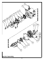
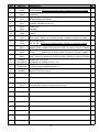
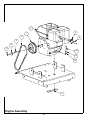
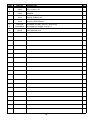
1
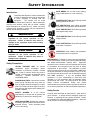
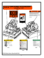
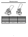
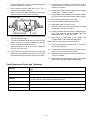
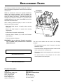
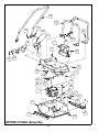
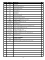
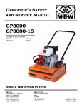
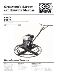
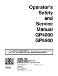
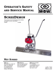
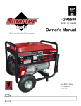
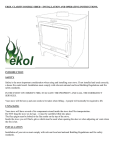
OPERATOR’S SAFETY
AND SERVICE MANUAL
GP3000
GP3000-15
This manual covers the following serial numbers
and higher for each model listed:
GP3000 . . . . . . . . . . . . . . . . . . . 1278189
GP3000-15 . . . . . . . . . . . . . . . . 1354198
SINGLE DIRECTION PLATES
MBW, Inc.
MBW (UK) Ltd.
250 Hartford Rd • PO Box 440
Slinger, WI 53086-0440
Phone: (262) 644-5234
Fax: (262) 644-5169
Email: [email protected]
Website: www.mbw.com
Unit 2 & 3 Cochrane Street
Bolton
BL3 6BN
Phone: 01204 387784
Fax: 01204 387797
L1313 / 02.12.E
©MBW, Inc. 2003
Printed in the USA
TABLE OF CONTENTS
Safety Information . . . . . . . . . . . . . . . . . . . . . . 1
Introduction . . . . . . . . . . . . . . . . . . . . . . . . . . . . . . . . . 1
Safety Precautions . . . . . . . . . . . . . . . . . . . . . . . . . . . 1
Safety Decals . . . . . . . . . . . . . . . . . . . . . . . . . . . . . . . 1
Engine Speed. . . . . . . . . . . . . . . . . . . . . . . . . . . . . . . 6
Cleaning Plate . . . . . . . . . . . . . . . . . . . . . . . . . . . . . . 6
Belt Adjustment . . . . . . . . . . . . . . . . . . . . . . . . . . . . . 6
Checking Exciter Oil . . . . . . . . . . . . . . . . . . . . . . . . . . 7
Changing Exciter Oil. . . . . . . . . . . . . . . . . . . . . . . . . . 7
Specifications. . . . . . . . . . . . . . . . . . . . . . . . . . 4
Service. . . . . . . . . . . . . . . . . . . . . . . . . . . . . . . . 8
Operation . . . . . . . . . . . . . . . . . . . . . . . . . . . . . 5
Torque Chart . . . . . . . . . . . . . . . . . . . . . . . . . . . . . . . 8
Introduction . . . . . . . . . . . . . . . . . . . . . . . . . . . . . . . . . 5
Exciter Disassembly . . . . . . . . . . . . . . . . . . . . . . . . . . 8
Before Starting & Operating . . . . . . . . . . . . . . . . . . . . 5
Exciter Assembly . . . . . . . . . . . . . . . . . . . . . . . . . . . . 8
Starting Engine . . . . . . . . . . . . . . . . . . . . . . . . . . . . . . 5
Parts Replacement Cycles and Tolerances . . . . . . . . 9
Operating . . . . . . . . . . . . . . . . . . . . . . . . . . . . . . . . . . 5
Stopping Engine . . . . . . . . . . . . . . . . . . . . . . . . . . . . . 5
Maintenance . . . . . . . . . . . . . . . . . . . . . . . . . . . 6
Replacement Parts . . . . . . . . . . . . . . . . . . . . . 11
GP3000 Main Assembly. . . . . . . . . . . . . . . . . . . . . . 12
GP3000-15 Main Assembly . . . . . . . . . . . . . . . . . . . 14
Maintenance Schedule . . . . . . . . . . . . . . . . . . . . . . . . 6
Exciter Assembly . . . . . . . . . . . . . . . . . . . . . . . . . . . 16
Fluid Levels. . . . . . . . . . . . . . . . . . . . . . . . . . . . . . . . . 6
Engine Assembly . . . . . . . . . . . . . . . . . . . . . . . . . . . 18
Engine Maintenance . . . . . . . . . . . . . . . . . . . . . . . . . . 6
Warranty . . . . . . . . . . . . . . . . . . . . . . . . . . . . . 20
This page intentionally left blank.
SAFETY INFORMATION
Introduction
SAFE DRESS: Do not wear loose clothing,
rings, wristwatches, etc. near machinery.
This Safety Alert Symbol is used to call attention
to items or operations which may be dangerous
to those operating or working with this
equipment.
The symbol can be found
throughout this manual and on the unit. Please read these
warnings and cautions, along with all decals, carefully
before attempting to operate the unit. Make sure every
individual who operates or works with this equipment is
familiar with all safety precautions.
NOISE PROTECTION: Wear OSHA specified
hearing protection devices.
EYE PROTECTION: Wear OSHA specified
eye shields, safety glasses, and sweat bands.
FOOT PROTECTION: Wear OSHA specified
steel-tipped safety shoes.
WARNING
HEAD PROTECTION: Wear OSHA specified
safety helmets.
GENERAL WARNING.
Indicates information
important to the proper operation of the
equipment. Failure to observe may result in
damage to the equipment and/or severe bodily
injury or death.
DUST PROTECTION: Wear OSHA specified
dust mask or respirator.
CAUTION
OPERATOR: Keep children and bystanders
off and away from the equipment.
GENERAL CAUTION.
Indicates information
important to the proper operation of the
equipment. Failure to observe may result in
damage to the equipment.
REFERENCES: For details on safety rules and regulations
in the United States, contact your local Occupational Safety
and Health Administration (OSHA) office. Equipment
operated in other countries must be operated and serviced
in accordance and compliance with any and all safety
requirements of that country. The publication of these
safety precautions is done for your information. MBW does
not by the publication of these precautions, imply or in any
way represent that these are the sum of all dangers present
near MBW equipment.
If you are operating MBW
equipment, it is your responsibility to insure that such
operation is in full accordance with all applicable safety
requirements and codes. All requirements of the United
States Federal Occupational Safety and Health
Administration Act must be met when operated in areas that
are under the jurisdiction of that United States Department.
Safety Precautions
LETHAL EXHAUST GAS: An internal
combustion engine discharges carbon
monoxide, a poisonous, odorless, invisible
gas. Death or serious illness may result if
inhaled. Operate only in an area with proper
ventilation.
NEVER OPERATE IN A
CONFINED AREA!
DANGEROUS FUELS: Use extreme caution
when storing, handling and using fuels, as
they are highly volatile and explosive in vapor
state. Do not add fuel while engine is running.
Stop and cool the engine before adding fuel.
DO NOT SMOKE!
Safety Decals
SAFETY GUARDS: It is the owner's
responsibility to ensure that all guards and
shields are in place and in working order.
Carefully read and follow all safety decals. Keep them in
good condition. If decals become damaged, replace as
required. If repainting the unit, replace all decals. Decals
are available from authorized MBW distributors. Order the
decal set listed on the following page(s).
IGNITION SYSTEMS: Breakerless, magneto,
and battery ignition systems can cause severe
electrical shocks. Avoid contacting these
units or their wiring.
-1-
01062
WARNING
OPERATION OF THIS EQUIPMENT MAY
CREATE SPARKS THAT CAN START FIRES
AROUND DRY VEGETATION. A SPARK
ARRESTER MAY BE REQUIRED. THE
OPERATOR SHOULD CONTACT LOCAL FIRE
AGENCIES FOR LAWS OR REGULATIONS
19791
RELATING TO FIRE PREVENTION
19791
01064
13484
CAUTION
CAUTION
Machine may fall and cause
damage or injury if lifted
incorrectly.
Lift using handles at
base of plate.
GP3000-15= #215 (98kg)
GP3000=
#250 (114kg)
GP5500=
#300 (137kg)
13478
STOP
13478
Read the Operating Instructions
before operating this piece of
equipment.
Keep unauthorized and untrained
people away from this
equipment.
!"
#$#
ROTATING & MOVING PARTS!
Make sure all guards and safety
devices are in place.
Wear approved hearing protection,
foot protection, eye protection and
head protection.
0 !*'
/*$'*1
2
'*"'
*'**
*
+
/*
SHUT OFF the motor before servicing or cleaning.
DO NOT RUN in an enclosed area.
The engine produces carbon
monoxide, a POISONOUS GAS.
Failure to comply could result in serious
bodily injury.
13483
13483
GP3000 Safety Decals (Decal Set #12100)
-2-
% &$'(
($)
*
+
*
,
+
- *'**
$'*
&$)
. "
/*$'*'
' 3 "'
'$*2
&
4//#
,$
/
*+2
($4("(
( $*
$/
,
'$+
5 /* 1
*"'
*'**
*
+
/*2
"/
/* /&*2
/
!"
#$#
%-5
13482
WARNING
CAUTION
OPERATION OF THIS EQUIPMENT MAY
CREATE SPARKS THAT CAN START FIRES
AROUND DRY VEGETATION. A SPARK
ARRESTER MAY BE REQUIRED. THE
OPERATOR SHOULD CONTACT LOCAL FIRE
AGENCIES FOR LAWS OR REGULATIONS
19791
RELATING TO FIRE PREVENTION
Read the Operating Instructions
before operating this piece of
equipment.
Keep unauthorized and untrained
people away from this
equipment.
ROTATING & MOVING PARTS!
Make sure all guards and safety
devices are in place.
Wear approved hearing protection,
foot protection, eye protection and
head protection.
19791
STOP
SHUT OFF the motor before servicing or cleaning.
DO NOT RUN in an enclosed area.
The engine produces carbon
monoxide, a POISONOUS GAS.
Failure to comply could result in serious
bodily injury.
13483
13483
!"
#$#
% &$'(
($)
*
+
*
,
+
- *'**
$'*
&$)
. "
/*$'*'
' 0 !*'
/*$'*1
2
'*"'
*'**
*
+
/*
3 "'
'$*2
&
4//#
,$
/
*+2
($4("(
( $*
$/
,
'$+
5 /* 1
*"'
*'**
*
+
/*2
"/
/* /&*2
/
!"
#$#
%-5
13482
01064
CAUTION
Machine may fall and cause
damage or injury if lifted
incorrectly.
Lift using handles at
base of plate.
GP3000-15= #215 (98kg)
GP3000=
#250 (114kg)
GP5500=
#300 (137kg)
13478
01064
13478
01062
GP3000-15 Safety Decals (Decal Set #12100)
-3-
13484
SPECIFICATIONS
3000H
3000-15H
GP3000
GP3000-15
Centrifugal Force
3550 lbs (1611 kg)
3550 lbs (1611 kg)
Exciter VPM
4400
4400
Travel Speed
90 ft/min (28 m/min)
120 ft/min (36 m/min)
Compaction Depth
18 in (47 cm)
16 in (41 cm)
Width & Length
21 x 22 in (53 x 56 cm)
16 x 20 in (40 x 51 cm)
Operating Weight (Honda)
234 lbs (106 kg)
202 lbs (91 kg)
Engine Speed
3400 rpm
3400 rpm
Engine
Honda 5.5 hp
Robin 4.5 hp
Honda 5.5 hp
Robin 4.5 hp
Specifications subject to change without notice
-4-
OPERATION
Introduction
MBW equipment is intended for use in very severe
applications. They are powered by four cycle engines and
are available in different sizes and a selection of engines.
This parts manual contains only standard parts. Variations
of these parts as well as other special parts are not included.
Contact your local MBW distributor for assistance in
identifying parts not included in this manual.
2.
Turn engine switch to “ON”.
3.
Set throttle to idle.
4.
Choke engine if necessary (you may not need to
choke a warm engine).
5.
Pull starter rope repeatedly until engine starts.
6.
Move choke lever to open position.
7.
Allow engine to warm up for one or two minutes.
Operating
Before Starting & Operating
• REMEMBER! It is the owner’s responsibility to
communicate information on the safe use and proper
operation of this unit to the operators.
• Review ALL of the Safety Precautions listed on page 1 of
this manual.
• Familiarize yourself with the operation of the machine
and confirm that all controls function properly.
1.
Open throttle fully.
2.
Compactor will begin vibrating and moving in a
forward direction.
3.
Maximum compaction of soil has been reached when
excessive kickback is noticed in the compactor. The
number of passes needed to reach compaction level
desired will depend on soil type and moisture.
4.
When using the compactor on asphalt use the water
sprinkling system to keep the plate bottom from
adhering to the hot asphalt.
• Know how to STOP the machine in case of an
emergency.
Stopping Engine
• Make sure hands, feet, and clothing are at a safe
distance from any moving parts.
• OIL LEVEL - Check the oil level in the engine. For more
information see “Lubrication” under the respective
engine’s “Owners Manual” or the Maintenance section
of this manual.
• AIR CLEANER - Check to ensure element is in good
condition and properly installed.
Move throttle to idle position.
2.
Let engine idle for one or two minutes.
3.
Turn switch on engine to “STOP” position.
4.
Turn off fuel valve.
WARNING
Always stop the engine before:
• FUEL SUPPLY - The engines on MBW equipment
require an automotive grade of clean, fresh, unleaded
gasoline.
Adding fuel.
Leaving the equipment unattended for any
amount of time.
• FUEL FILTER - If clogged or damaged, replace.
Before making any repairs or adjustments to the
machine.
Starting Engine
1.
1.
Open fuel valve.
-5-
MAINTENANCE
WARNING
CAUTION
Always exercise the stopping procedure before
servicing or lubricating the unit.
Always verify fluid levels and check for leaks after
changing fluids.
After servicing the unit, replace and fasten all
guards, shields, and covers to their original
positions before resuming operation.
Do not drain oil onto ground, into open streams,
or down sewage drains.
Maintenance Schedule
SYSTEM
MAINTENANCE
EACH USE
Engine
Refer to engine operator/owner manual
Exciter
Check oil level
EVERY 50
HOURS
EVERY 250
HOURS
YEARLY
X
X
X
X
Check for oil leaks
X
Change oil
Tighten Bolts1
X
X
Hardware
Check and tighten as needed1
X
X
Shockmounts
Check for cracks or tears
X
X
1.
Check all hardware after the first 5 hours of use, then follow the maintenance schedule.
Fluid Levels
SYSTEM
FLUID VOLUME
RECOMMENDED OIL
Exciter
8 oz
MBW Ground Pounder® Exciter Oil1
Engine
1.
Refer to engine operator/owner manual
MBW #01058 ---- 6-Pack (8 oz bottles)
MBW #17320 ---- 1 quart (32 oz)
MBW #01469 ---- 1 gallon (U.S.)
Engine Maintenance
Cleaning Plate
Refer to the engine owner’s manual for maintenance
intervals and procedures.
Remove any excess debris which may get into the housing
of the unit.
Engine Speed
Belt Adjustment
1.
2.
Engine speed is factory set according to the speeds
listed in the Specifications section of this manual.
Refer to the engine owner’s manual for procedure on
setting operating speed if necessary.
If any belt stretch develops follow these steps:
Reference the figure on page 18.
The idle speed of the engine must not exceed 1800
rpm. If the idle speed is greater the clutch may not
disengage.
Check engine owner’s manual for
procedure on setting idle speed.
-6-
1.
Remove belt guard.
2.
Loosen (do not remove) the four engine bolts (#9).
3.
Pull engine back to remove any slack in v-belt (#3).
4.
Retighten engine bolts.
5.
Install belt guard.
Checking Exciter Oil
WARNING
8.
If oil needs to be added refer to Fluid Levels, page 6
for the type of oil to be used.
9.
Reinstall pipe plug.
10. Reinstall deck, v-belt and belt guard.
Exciter and oil in exciter is hot after machine has
been running.
Changing Exciter Oil
These instructions are written for a GP3000. The procedure
for a GP3000-15 is very similar.
WARNING
Exciter and oil in exciter is hot after machine has
been running.
Reference the figure on page 12.
1.
Let exciter cool before changing exciter oil.
2.
Remove the belt guard (#5) and v-belt (page 18, #3).
3.
Remove the bolts (#29) that hold the deck (#2) to the
housing (#1).
4.
Lift entire deck with engine from housing.
5.
Remove pipe plug (page 16, #23) on top of exciter.
6.
Rotate exciter shaft so a metal dip stick kind can be
inserted into exciter (see Figure 1).
DIP STICK
These instructions are written for a GP3000. The procedure
for a GP3000-15 is very similar.
Reference the figure on page 12.
Figure 1
1.
Let exciter cool before changing exciter oil.
2.
Remove the belt guard (#5) and v-belt (page 18, #3).
3.
Remove the bolts (#29) that hold the deck (#2) to the
housing (#1).
4.
Lift entire deck with engine from housing.
5.
Remove drain screw (page 16, #19) and brass
washer (page 16, #22) from the rear cover (page 16,
#9).
6.
Tilt housing upside down so oil drains from exciter
(#3). (Examine oil for metal chips as a precaution to
future problems.)
7.
Tip housing upright and replace drain screw and
brass washer.
8.
Remove pipe plug (page 16, #23) on top of exciter.
9.
Fill exciter according to Fluid Levels, page 6.
EXCITER
EXCITER
SHAFT
7.
OIL LEVEL
7/8" MIN
1" MAX
10. Reinstall pipe plug.
11. Reinstall deck, v-belt and belt guard.
The oil level should be between 7/8” to 1” deep on
bottom of exciter (see Figure 1).
-7-
SERVICE
Exciter Disassembly
Assembly and disassembly should be performed by a
service technician who has been factory trained on MBW
equipment. The unit should be clean and free of debris.
Pressure washing before disassembly is recommended.
Steps 1 thru 6 reference the figure on page 12.
1.
Remove the belt guard (#5) and v-belt (page 18, #3).
• Prior to assembly, wash all parts in a suitable cleaner or
solvent.
2.
Remove the bolts (#29) that hold the deck (#2) to the
housing (#1).
• Check moving parts for wear and failure. Refer to the
Replacement section in this manual for tolerance and
replacement cycles.
3.
Lift entire deck with engine from housing.
4.
Remove the four exciter hold down bolts (#18).
5.
Lift the exciter (#3) from the housing (#1).
• All shafts and housings should be oiled prior to pressing
bearings. Also, ensure that the bearings are pressed
square and are seated properly.
6.
Clean the exciter before proceeding with the
disassembly.
Steps 7 thru 17 reference the figure on page 16.
• All bearings should be replaced when rebuilding any
exciter or gearbox.
7.
Remove the flange screw (#21) and washer (#14)
securing the pulley (#3) to the exciter shaft (#2).
• All gaskets and seals should be replaced after any
disassembly.
8.
Slide the pulley off the exciter shaft. Be careful not to
lose the key (#15).
9.
Remove rear cover (#5) by unscrewing the six flange
screws (#21).
Torque Chart
SIZE
1/4-20
1/4-28
5/16-18
5/16-24
3/8-16
3/8-24
7/16-14
7/16-20
1/2-13
1/2-20
9/16-12
5/8-11
5/8-18
3/4-16
1-8
1-14
1-1/2-6
M6
M8
M 10
GRADE 2
GRADE 5
49 in•lbs
76 in•lbs
56 in•lbs
87 in•lbs
8 ft•lbs
13 ft•lbs
9 ft•lbs
14 ft•lbs
15 ft•lbs
23 ft•lbs
17 ft•lbs
26 ft•lbs
24 ft•lbs
37 ft•lbs
27 ft•lbs
41 ft•lbs
37 ft•lbs
57 ft•lbs
41 ft•lbs
64 ft•lbs
53 ft•lbs
82 ft•lbs
73 ft•lbs
112 ft•lbs
83 ft•lbs
112 ft•lbs
144 ft•lbs
200 ft•lbs
188 ft•lbs
483 ft•lbs
210 ft•lbs
541 ft•lbs
652 ft•lbs
1462 ft•lbs
3 ft•lbs
4 ft•lbs
6 ft•lbs
10 ft•lbs
10 ft•lbs
20 ft•lbs
CONVERSIONS
in•lbs x 0.083 = ft•lbs
ft•lbs x 12 = in•lbs
ft•lbs x 0.1383 = kg•m
ft•lbs x 1.3558 = N•m
10. Block exciter housing (#1) on large O.D. side (rear
cover side), then press exciter shaft through exciter
housing.
GRADE 8
9 ft•lbs
10 ft•lbs
18 ft•lbs
20 ft•lbs
33 ft•lbs
37 ft•lbs
52 ft•lbs
58 ft•lbs
80 ft•lbs
90 ft•lbs
115 ft•lbs
159 ft•lbs
180 ft•lbs
315 ft•lbs
682 ft•lbs
764 ft•lbs
2371 ft•lbs
7 ft•lbs
18 ft•lbs
30 ft•lbs
11. Remove front cover (#4) by unscrewing the six flange
screws (#20).
12. Remove bearing (#12) from exciter housing by
pressing it out from the inside.
13. Remove retainer (#7) by unscrewing the two cap
screws (#19).
14. Remove snap ring (#8).
15. Remove bearing (#11) from rear cover (#5) by using
a 1/4” punch. Tap the bearing out thru the holes from
the cap srews in step 13. Be sure to alternate
between holes to avoid cocking the bearing.
16. Remove snap ring (#9).
17. Remove inner race of bearing (#11) from the exciter
shaft by supporting the O.D. of the race and pressing
the exciter shaft thru.
Exciter Assembly
Steps 1 thru 19 reference the figure on page 16.
-8-
1.
Press bearing (#12) into exciter housing (#1). Use
care to press on the O.D. of the bearing only.
2.
Press the inner race of bearing (#11) onto exciter
shaft (#2).
3.
Install snap ring (#9) onto exciter shaft.
4.
Properly support I.D. and O.D. of bearing (#12) and
press exciter shaft into bearing.
5.
Check felt filter (#13) to make sure it is ok. If it is
blocked or deteriorating replace it.
6.
11. Carefully press or tap the rear cover down to seat on
the exciter housing. Be sure to use care in order to
keep the cover even.
12. Remove the alignment bolts and install six flange
screws (#21). Torque to 13 ft-lbs.
Check to make sure spirol pin (#18) is 11/16” (see
Figure 2) up from inside of rear cover (#5).
13. Using medium strength thread lock install the retainer
(#7), three cap screws (#19) and brass washer (#22).
Figure 2
SPIROL PIN
14. Press oil seal (#10) into front cover (#4).
15. Install seal washer (#6) onto exciter shaft.
16. Install gasket (#16) onto front cover.
17. Intall front cover onto exciter housing with six flange
screws (#20). Torque to 13 ft-lbs.
REAR COVER
7.
Press bearing (#11) into rear cover and install snap
ring (#8) and gasket (#17).
8.
To aid in the assembly of the rear cover you will need
three 5/16-18 x 2-1/2” minimum length bolts that will
help in the alignment of the rear cover.
9.
18. Grease oil seal lip and exciter shaft. Install pulley (#3)
onto exciter shaft with key (#15), washer (#14) and
flange screw (#21). Torque to 13 ft-lbs.
11/16"
19. Add exciter oil (see page 6 for quantity and
recommended oil) and install pipe plug (#23).
Steps 20 thru 23 reference the figure on page 12.
20. Clean mounting bars on housing (#1). Set exciter
(#3) on mounting bars.
Apply some oil to the I.D. of the exciter housing and
the O.D. of the rear cover.
21. Check to make sure exciter sits flat on all four mount
points, if not use shims (#11) as needed.
10. Set the rear cover on top of the exciter housing and
install the three alignment bolts thru the rear cover
and thread them three turns into the exciter housing.
22. Install four exciter bolts (#18) and lock washers (#31).
Torque to 150 ft-lbs.
23. Reassemble deck (#2), engine (page 18, #4), v-belt
(page 18, #3), beltguard (#5) and handle (#6).
Parts Replacement Cycles and Tolerances
Bearings
Replace anytime a bearing is rough, binding, discolored or removed from housing or
shaft.
Clutch
Replace clutch if it does not disengage below 1800 rpm.
Engine Components
Refer to your engine manufacturer’s Owner’s Manual.
Hardware
Replace any worn or damaged hardware as needed. Replacement hardware should
be grade 5 and zinc plated unless otherwise specified.
Safety Decals
Replace if they become damaged or illegible.
Seals & Gaskets
Replace if a leak is detected and at every overhaul or teardown.
V-Belts
Replace if cracked, torn, or stretched to the point the belt won’t tension properly.
-9-
This page intentionally left blank.
- 10 -
REPLACEMENT PARTS
The warranty is stated in this book on page 20. Failure to
return the Warranty Registration Card renders the warranty
null and void.
STAMPED
LOCATION
MBW has established a network of reputable distributors/
dealers with trained mechanics and full facilities for
maintenance and rebuilding, and to carry an adequate parts
stock in all areas of the country. Their sales engineers are
available for professional consultation. If you cannot locate
an MBW distributor in your area, contact MBW or one of our
Sales Branches listed below.
When ordering replacement parts, be sure to have the
following information available:
• Model and Serial Number of machine when ordering
MBW parts
• Model and Serial Number of engine when ordering
engine parts
• Part Number, Description, and Quantity
• Company Name, Address, Zip Code, and Purchase
Order Number
DECAL
LOCATION
• Preferred method of shipping
REMEMBER - You own the best! If repairs are needed,
use only MBW parts purchased from authorized
MBW distributors.
The unit’s serial number can be found in the following
locations:
• The model/serial number decal is located on the deck
behind the engine.
• The serial number is stamped on the deck in the back left
corner by the roll bar mounting holes.
• The serial number is also stamped on the exciter next to
the fill hole.
Write Model Number here
• The serial number is also stamped on the exciter
mounting bars on the base plate.
Write Serial Number here
Contact Information
MBW, Inc.
250 Hartford Rd • PO Box 440
Slinger, WI 53086-0440
Phone: (262) 644-5234
Fax: (262) 644-5169
Email: [email protected]
Website: www.mbw.com
MBW (UK) Ltd.
Units 2& 3 Cochrane Street
Bolton
BL3 6BN, England
Phone: 01204 387784
Fax: 01204 387797
- 11 -
6
17
23
14
5
16
15
4
25
2
9
24
29
30
13
24
28
30
19
24
10
20
21
18
22
31
3
11
12
29
30
1
8
26
7
27
GP3000 Main Assembly
- 12 -
ITEM
1.
2.
3.
4.
5.
6.
7.
8.
9.
10.
11.
12.
13.
14.
15.
16.
17.
18.
19.
20.
21.
22.
23.
24.
25.
26.
27.
28.
29.
30.
31.
PART NO.
00008
00014
19913
00025
00028
00034
0042L
0042R
00048
00050
00259
01011
01012
01018
01019
01056
02462
06054
F042006HCS
F0420HN
F04LW
F04SW
F051806FWS
F0518FN
F061607FWS
F061608FWS
F0616FN
F081305HCS
F081306HCS
F08LW
F10LW
01022
01023
01629
02408
02464
DESCRIPTION
HOUSING, GP3000 (Includes items 7, 8, 26 & 27)
DECK, GP3000
EXCITER, GP3000
BRACKET, HANDLE
BELTGUARD
HANDLE, GP3000 (Includes items 14 & 15)
BAR, MOLD LEFT GP3000
BAR, MOLD RIGHT GP3000
HOOK BOLT
APRON, RUBBER GP3000
SHIM (as needed)
SHOCKMOUNT
SHOCKMOUNT
BUSHING, NYLON OUTER
BUSHING, NYLON INNER
HAIRPIN
BAR, ROLL GP3000 (Optional)
HEX HEAD CAP SCREW, 5/8-18 x 5-1/2” GR8
HEX HEAD CAP SCREW, 1/4-20 x 3/4”
HEX NUT, 1/4-20
LOCK WASHER, 1/4”
WASHER, 1/4”
FLANGE LOCKING SCREW, 5/16-18 x 3/4” (with Roll Bar only)
FLANGE LOCKING NUT, 5/16-18 (8 with Roll Bar only)
FLANGE LOCKING SCREW, 3/8-16 x 7/8”
FLANGE LOCKING SCREW, 3/8-16 x 1”
FLANGE LOCKING NUT, 3/8-16
HEX HEAD CAP SCREW, 1/2-13 x 5/8”
HEX HEAD CAP SCREW, 1/2-13 x 3/4”
LOCK WASHER, 1/2”
LOCK WASHER, 5/8”
OPTIONAL ACCESSORIES
SPRINKLING SYSTEM KIT, GP3000
JOB CART, GP3000
TEST MAT
HEAVY DUTY HOUSING, GP3000
ROLL BAR KIT, GP3000 (Includes items 17, 23 & 24)
- 13 -
QTY
1
1
1
2
1
1
1
1
1
1
5
4
2
2
2
1
4
3
3
3
3
8
10
2
10
10
5
13
18
4
15
14
11
12
22
13
17
2
10
28
29
8
24
9
27
29
23
29
18
26
6
19
20
21
16
30
1
7
9
27
29
5
4
24
3
25
GP3000-15 Main Assembly
- 14 -
ITEM
1.
2.
3.
4.
5.
6.
7.
8.
9.
10.
11.
12.
13.
14.
15.
16.
17.
18.
19.
20.
21.
22.
23.
24.
25.
26.
27.
28.
29.
30.
PART NO.
19913
00028
0049L
0049R
00160
00174
00259
00308
01011
01012
01018
01019
01056
02473
02710
06054
06921
F042006HCS
F0420HN
F04LW
F04SW
F051806FWS
F0518FN
F061607FWS
F0616FN
F081305HCS
F081306HCS
F081307HCS
F08LW
F10LW
01038
01629
02472
07213
DESCRIPTION
EXCITER, GP3000
BELTGUARD
BAR, MOLD LEFT GP3000-15
BAR, MOLD RIGHT GP3000-15
HOUSING, GP3000-15 (Includes items 3, 4, 24 & 25)
APRON, RUBBER GP3000
SHIM (as needed)
DECK, GP3000-15
SHOCKMOUNT
SHOCKMOUNT
BUSHING, NYLON OUTER
BUSHING, NYLON INNER
HAIRPIN
BAR, ROLL GP3000-15 (Optional)
HANDLE, GP3000-15 (Includes items 11 & 12)
HEX HEAD CAP SCREW, 5/8-18 x 5-1/2” GR8
BRACKET, HANDLE
HEX HEAD CAP SCREW, 1/4-20 x 3/4”
HEX NUT, 1/4-20
LOCK WASHER, 1/4”
WASHER, 1/4”
FLANGE LOCKING SCREW, 5/16-18 x 3/4” (with Roll Bar only)
FLANGE LOCKING NUT, 5/16-18” (with Roll Bar only)
FLANGE LOCKING SCREW, 3/8-16 x 7/8”
FLANGE LOCKING NUT, 3/8-16
HEX HEAD CAP SCREW, 1/2-13 x 5/8”
HEX HEAD CAP SCREW, 1/2-13 x 3/4”
HEX HEAD CAP SCREW, 1/2-13 x 7/8” (with Roll Bar only)
LOCK WASHER, 1/2”
LOCK WASHER, 5/8”
OPTIONAL ACCESSORIES
JOB CART, GP3000-15
TEST MAT
ROLL BAR KIT, GP3000-15 (Includes items 14, 22, 23 & 28)
SPRINKLING SYSTEM KIT, GP3000-15
- 15 -
QTY
1
1
1
1
1
1
1
7
2
2
2
2
1
1
4
2
3
3
3
3
4
4
8
6
5
13
2
18
4
Exciter Assembly
- 16 -
ITEM
1.
2.
3.
4.
5.
6.
7.
8.
9.
10.
11.
12.
13.
14.
15.
16.
17.
18.
19.
20.
21.
22.
23.
PART NO.
00001
00062
00006
00066
01000
01001
01004
01005
01072
01099
06096
06098
17179
01002
19135
01283
19628
00005
19629
00003
19912
00002
F0205SP
F051804HCS
F051806FWS
F051808FWS
F05BFW
F0618SPP
19913
DESCRIPTION
QTY
HOUSING, EXCITER
1
WASHER SEAL SERIAL NO. GP3000 1278190 - GP3000-15 1354197 & LOWER
COVER, REAR
1
RETAINER
1
RETAINING RING, INTERNAL
1
RETAINING RING, EXTERNAL
1
BEARING, CYLINDRICAL ROLLER
1
BEARING, SPHERICAL ROLLER
1
FILTER, FELT
1
WASHER
1
GASKET
1
GASKET
1
SEAL, SHAFT, 1.25”
1
SEAL, SHAFT SERIAL NO. GP3000 1278190 - GP3000-15 1354197 & LOWER
KEY, 1/4 SQ x 3/4 lg.
1
KEY 1/4” SQ. SERIAL NO. GP3000 1278190 - GP3000-15 1354197 & LOWER
COVER, FRONT
1
COVER, FRONT SERIAL NO. GP3000 1278190 - GP3000-15 1354197 & LOWER
PULLEY, EXCITER
1
PULLEY
SERIAL NO. GP3000 1278190 - GP3000-15 1354197 & LOWER
SHAFT, EXCITER
1
SHAFT, EXCITER SERIAL NO. GP3000 1278190 - GP3000-15 1354197 & LOWER
SPIROL PIN, 1/8 x 5/8 RD
1
HEX HEAD CAP SCREW, 5/16-18 x 1/2”
3
FLANGE LOCKING SCREW, 5/16-18 x 3/4”
6
FLANGE LOCKING SCREW, 5/16-18 x 1”
7
BRASS WASHER, 5/16”
1
SOCKET PIPE PLUG, 3/8-18
1
REPLACEMENT KIT
EXCITER ASM, GP3000 (Contains all above items)
- 17 -
5
6
7
3
8
2
4
13
10
11
12
1
Engine Assembly
- 18 -
ITEM
1.
2.
3.
4.
5.
6.
7.
8.
9.
10.
11.
12.
PART NO.
00031
00808
01013
01099
01444
17210
07636
16105
F0203HTB
F052408HCS
F051814HCS
F05LW
F05SW
DESCRIPTION
BAR, MOUNTING
KEY, 1/4 SQ x 1-3/4
V-BELT
WASHER
ENGINE, HONDA 5.5hp
ENGINE, ROBIN 4.5hp
DEFLECTOR, EXHAUST (Honda only)
CLUTCH, CENTRIFUGAL
HEX HEAD TAP BOLT, #8 x 3/8” (Honda only)
HEX HEAD CAP SCREW, 5/16-24 X 1
HEX HEAD CAP SCREW, 5/16-18 x 1-3/4”
LOCK WASHER, 5/16”
WASHER, 5/16”
- 19 -
QTY
2
1
1
1
1
1
1
1
2
1
4
4
4
WARRANTY
WHAT DOES THIS WARRANTY COVER? MBW, Incorporated (MBW)
warrants each New Machine against defects in material and workmanship
for a period of twelve (12) months. "New Machine" means a machine
shipped directly from MBW or authorized MBW dealer to the end user. This
warranty commences on the first day the machine is sold, assigned to a
rental fleet, or otherwise put to first use.
MBW warrants each Demonstration Machine against defects in material
and workmanship for a period of six (6) months. "Demonstration Machine"
means a machine used by MBW or its agents for promotional purposes.
This warranty commences on the first day the machine is sold, assigned to
a rental fleet, or otherwise put to first use.
This warranty covers the labor cost for replacement or repair of parts,
components, or equipment on New Machines or Demonstration Machines,
and MBW shall pay labor costs at MBW's prevailing rate to affect the
warranted repair or replacement. MBW reserves the right to adjust labor
claims on a claim-by-claim basis.
This warranty covers the shipping cost of replacement parts, components,
or equipment via common ground carriers from MBW to an authorized
MBW dealer. Air freight is considered only in cases where ground
transportation is not practical.
MAY THIS WARRANTY BE TRANSFERRED? This warranty is nontransferable and only applies to the original end user of a new machine or
demonstration machine.
WHAT DOES THIS WARRANTY NOT COVER?
1.This warranty does not cover any Used Equipment. "Used Equipment"
means any MBW machine or equipment that is not a New Machine or a
Demonstration Machine. All Used Equipment is sold AS IS/WHERE IS
WITH ALL FAULTS.
2.This warranty does not cover any New Machine, Demonstration
Machine, or their equipment, parts, or components altered or modified in
any way without MBW's prior written consent. This warranty does not
cover the use of parts not specifically approved by MBW for use on MBW
products. This warranty does not cover misuse, neglect, shipping damage,
accidents, acts of God, the operation of any New Machine or
Demonstration Machine in any way other than recommended by MBW in
accordance with its specifications, or any other circumstances beyond
MBW's control. This warranty does not cover any New Machine or
Demonstration Machine repaired by anyone other than MBW factory
branches or authorized MBW distributors.
3.This warranty does not cover, and MBW affirmatively disclaims, liability
for any damage or injury resulting directly or indirectly from design,
materials, or operation of a New Machine or Demonstration Machine or any
other MBW product. MBW's liability with respect to any breach of warranty
shall be limited to the provisions of this document and in no event shall
exceed an amount equal to the purchase price of the New Machine or
Demonstration Machine purchased from MBW.
4.This warranty does not cover engines, motors, and other assemblies or
components produced by other manufacturers and used on a New
Machine or Demonstration Machine, as said engines, motors, and other
assemblies or components may have warranties provided by the
manufacturer thereof. This warranty does not apply to consumable items,
such as v-belts, filters, trowel and screed blades, seals, shock mounts,
batteries, and the like, all of which are sold AS IS/WHERE IS WITH ALL
FAULTS.
5.This warranty does not cover the cost of transportation and other
expenses which may be connected with warranty service but not
specifically mentioned herein.
6.This warranty does not cover any updates to any New Machine,
Demonstration Machine, or any other MBW product. MBW reserves the
right to improve or make product changes without incurring any obligation
to update, refit, or install the same on New Machines or Demonstration
Machines previously sold.
WHAT MUST YOU DO TO OBTAIN WARRANTY COVERAGE? Each
New Machine or Demonstration Machine is accompanied by a Warranty
Registration Card. You must sign, date, and return the Warranty
Registration Card to the place of origin of the New Machine or
Demonstration Machine, either to MBW, Inc. at P.O. Box 440, Slinger,
Wisconsin 53086, MBW (UK), Ltd. at Units 2 & 3 Cochrane Street, Bolton
BL3 6BN, United Kingdom or MBW FRANCE SARL at
ZA D'Outreville, 5 Rue Jean Baptiste Neron, Bornel 60540 France, within
ten (10) days after purchase, assignment to a rental fleet, or first use. This
signed warranty card is the buyer's affirmation that he has read,
understood, and accepted the warranty at the time of purchase. Failure to
return the warranty card as specified herein renders the warranty null and
void. In order to receive warranty coverage consideration, warranty claims
must be submitted within thirty (30) days after the New Machine or
Demonstration Machine fails. Warranty claims must be submitted to MBW,
Inc., MBW (UK), Ltd. or MBW FRANCE SARL, and written authorization for
the return of merchandise or parts under the warranty must be obtained
before shipment to MBW.
WHAT WILL MBW DO? MBW's obligation under this warranty is limited to
the replacement or repair of parts for a New Machine or Demonstration
Machine at MBW factory branches or at authorized MBW distributors, and
such replacement or repair is the exclusive remedy provided hereunder.
Labor must be performed at an authorized MBW distributor. MBW
reserves the right to inspect and render a final decision on each warranty
case, and MBW's repair or replacement is solely within the discretion of
MBW.
IT IS EXPRESSLY AGREED THAT THIS SHALL BE THE SOLE AND
EXCLUSIVE REMEDY UNDER THIS WARRANTY. UNDER NO
CIRCUMSTANCES SHALL MBW BE LIABLE FOR ANY COSTS, LOSS,
EXPENSE, DAMAGES, SPECIAL DAMAGES, INCIDENTAL DAMAGES,
OR PUNITIVE DAMAGES ARISING DIRECTLY OR INDIRECTLY FROM
THE USE OF THE NEW MACHINE OR DEMONSTRATION MACHINE
WHETHER BASED UPON WARRANTY, CONTRACT, NEGLIGENCE,
STRICT LIABILITY, OR ANY OTHER LEGAL THEORY.
THE FOREGOING WARRANTY IS EXPRESSLY IN LIEU OF ALL
OTHER WARRANTIES, EXPRESS OR IMPLIED, INCLUDING THE
WARRANTIES OF MERCHANTABILITY, FITNESS FOR USE, AND
FITNESS FOR A PARTICULAR PURPOSE, AND ALL OTHER
OBLIGATIONS OR LIABILITY ON MBW'S PART. MBW NEITHER
ASSUMES NOR AUTHORIZES ANY OTHER PERSON TO ASSUME ON
BEHALF OF MBW ANY OTHER LIABILITY OR WARRANTY IN
CONNECTION WITH THE SALE OR SERVICE OF ANY NEW MACHINE,
DEMONSTRATION MACHINE , OR ANY OTHER MBW PRODUCT.
EXTENDED RAMMER WARRANTY - MODELS R422, R442,
R482 & R483.
This extended warranty commences on the last day of MBW’s standard,
one year, “limited warranty” and runs for an additional four years
(48 months). This extended warranty is limited to part replacement and
shipping costs of rammer bellows and non-metallic slide bearings only.
This extended warranty does not cover labor, down time, or any other cost
beyond that of component replacement and freight. This extended
warranty is subject to all limitations set fourth in MBW’s “limited warranty”,
above.
- 20 -
NOTES
- 21 -
NOTES
- 22 -