1
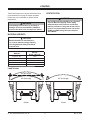
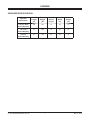
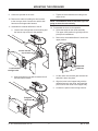
Blizzard, PO Box 245038, Milwaukee, WI 53224-9538 • www.blizzardplows.com May 15, 2012 Lit. No. 94195, Rev. 06 ICE CHASER™ Hopper Spreader #78002, 78005, 78008 Installation Instructions CAUTION Read this manual before installing or operating the spreader. These Installation Instructions are for BLIZZARD® ICE CHASER Hopper Spreaders with serial numbers beginning with 090528–120315. A DIVISION OF DOUGLAS DYNAMICS, L.L.C. SAFETY INFORMATION SAFETY DEFINITIONS WARNING/CAUTION LABELS Please become familiar with the Warning and Caution labels on the spreader. WARNING Indicates a potentially hazardous situation that, if not avoided, could result in death or serious personal injury. NOTE: If labels are missing or cannot be read, see your sales outlet. CAUTION Indicates a potentially hazardous situation that, if not avoided, may result in minor or moderate injury. It may also be used to alert against unsafe practices. CAUTION NOTE: Indicates a situation or action that can lead to damage to your spreader and vehicle or other property. Other useful information can also be described. Do not lift spreader by this member. Lifting here could cause personal injury and property damage. 67272 Both Sides Lit. No. 94193/94194/94195, Rev. 06 3 May 15, 2012 SAFETY INFORMATION SAFETY PRECAUTIONS CAUTION • Do not operate a spreader in need of maintenance. • Before operating the spreader, reassemble any parts or hardware removed for cleaning or adjusting. • Before operating the spreader, remove materials such as cleaning rags, brushes, and hand tools from the spreader. • While operating the spreader, use auxiliary warning lights, except when prohibited by law. • Tighten all fasteners according to the Torque Chart. Refer to Torque Chart for the recommended torque values. Improper installation and operation could cause personal injury and/or equipment and property damage. Read and understand labels and the Owner's Manual before installing, operating or making adjustments. WARNING • Driver to keep bystanders minimum of 25 feet away from operating spreader. • Before working with the spreader, secure all loose-fitting clothing and unrestrained hair. • Before operating the spreader, verify all safety guards are in place. • Before servicing the spreader, wait for conveyor and spinner to stop. • Do not climb into or ride on spreader. CAUTION Disconnect electric and/or hydraulic power and tag out if required before servicing or performing maintenance. WARNING Overloading could result in an accident or damage. Do not exceed GVWR or GAWR ratings as found on the driver-side door cornerpost of the vehicle. See Loading Section to determine maximum volumes of spreading material. CAUTION DO NOT leave unused material in hopper. Material can freeze or solidify, causing unit to not work properly. Empty and clean after each use. WARNING Do not install the control for this product in the deployment path of an air bag. Refer to vehicle manufacturer's manual for air bag deployment area(s). NOTE: Lubricate grease fittings after each use. Use a good quality multipurpose grease. PERSONAL SAFETY CAUTION • Remove ignition key and put the vehicle in park or in gear to prevent others from starting the vehicle during installation or service. If rear directional, CHMSL light or brake stoplights are obstructed by the spreader, the lights shall be relocated, or auxiliary directional or brake stoplights shall be installed. • Wear only snug-fitting clothing while working on your vehicle or spreader. • Do not wear jewelry or a necktie, and secure long hair. CAUTION During the hopper spreader installation we recommend the addition of an OSHA compliant Backup Alarm. This alarm is required for OSHA governed employers. • Wear safety goggles to protect your eyes from battery acid, gasoline, dirt and dust. • Avoid touching hot surfaces such as the engine, radiator, hoses and exhaust pipes. • Always have a fire extinguisher rated BC handy, for flammable liquids and electrical fires. Lit. No. 94193/94194/94195, Rev. 06 4 May 15, 2012 SAFETY INFORMATION CELL PHONES TORQUE CHART A driver's first responsibility is the safe operation of the vehicle. The most important thing you can do to prevent a crash is to avoid distractions and pay attention to the road. Wait until it is safe to operate Mobile Communication Equipment such as cell phones, text messaging devices, pagers or two-way radios. CAUTION Read instructions before assembling. Fasteners should be finger tight until instructed to tighten according to torque chart. Use standard methods and practices when attaching spreader including proper personal protective safety equipment. VENTILATION Recommended Fastener Torque Chart (ft-lb) WARNING Torque Vehicle exhaust contains lethal fumes. Breathing these fumes, even in low concentrations, can cause death. Never operate a vehicle in an enclosed area without venting exhaust to the outside. Size 1/4-20 5/16-18 3/8-16 3/8-24 7/16-14 1/2-13 9/16-12 5/8-11 3/4-10 7/8-9 1-8 BATTERY SAFETY CAUTION Batteries normally produce explosive gases which can cause personal injury. Therefore, do not allow flames, sparks or lit tobacco to come near the battery. When charging or working near a battery, always cover your face and protect your eyes, and also provide ventilation. • Batteries contain sulfuric acid which burns skin, eyes and clothing. • Disconnect the battery before removing or replacing any electrical components. SAE Grade 2 SAE Grade 5 SAE Grade 8 6 11 19 24 30 45 66 93 150 150 220 9 18 31 46 50 75 110 150 250 378 583 13 28 46 68 75 115 165 225 370 591 893 Metric Grade 8.8 (ft-lb) Size Torque Size Torque M6 M8 M 10 7 17 35 M 12 M 14 M 16 60 95 155 These torque values apply to fasteners except those noted in the instruction. NOISE Airborne noise emission during use is below 70 dB(A) for the spreader operator. VIBRATION Operating spreader vibration does not exceed 2.5 m/s2 to the hand-arm or 0.5 m/s2 to the whole body. Lit. No. 94193/94194/94195, Rev. 06 5 May 15, 2012 LOADING CERTIFICATION These instructions cover vehicles which have been recommended for carrying the hopper spreader. Please see your local dealer for proper vehicle applications. WARNING New untitled vehicle installation of a spreader requires National Highway Traffic Safety Administration altered vehicle certification labeling. Installer to verify that struck load of snow or ice control material does not exceed GVWR or GAWR rating label and complies with FMVSS. WARNING Overloading could result in an accident or damage. Do not exceed GVWR or GAWR as found on the driver-side cornerpost of vehicle. MATERIAL WEIGHTS CAUTION Read and adhere to manufacturer's ice-control material package labeling including Material Safety Data Sheet requirements. Material Density (lb per cubic yd) Fine Salt – Dry 1,350 Coarse Salt – Dry 1,215 Coarse Sand – Dry 2,700 Coarse Sand – Wet 3,240 Cinders 1,080 Load Volume 37" (2.5 cu yd) 27" (1.8 cu yd) 27" (1.5 cu yd) 8' Unit 7' Unit Lit. No. 94193/94194/94195, Rev. 06 6 May 15, 2012 LOADING SPREADER SPECIFICATIONS Spreader Description Regular Capacity 7' Hopper Body Double-Wall Poly 8' Hopper Body w/o Collar Double-Wall Poly 8' Hopper Body w/ Collar Double-Wall Poly Lit. No. 94193/94194/94195, Rev. 06 Overall Length (in) Empty Weight (lb) Capacity Struck (cu yd) Overall Width (in) Overall Height (in) 108 591 1.5 63 44 117 660 1.8 63 44 117 734 2.5 63 51 7 May 15, 2012 MOUNTING THE SPREADER 4. The spreader can be moved into the truck bed either by lifting the spreader by the four molded-in handles located on the corner legs or by sliding the spreader into the truck bed from the ground. NOTE: Periodically throughout the snow and ice control season, verify mounting devices are secure. CAUTION Before lifting, verify hopper is empty of material. The lifting device must be able to support the spreader's weight as shown in the spreader specifications table. 1. Remove the chute from the inside of the hopper: a. Unlatch the rubber straps located at the rear of the lids near the handles. b. Remove the screens. c. Remove the screen supports. Molded-In Handles (Both Sides) d. Remove the chute and replace the screen supports and screens. 5. To lift the spreader into the truck bed from the ground, stand the spreader up on the feet at the rear of the spreader on top of two spacers at least 2" off the ground. The chute must be removed. e. Close the lids and latch the rubber straps. 2. Remove the tailgate from the truck. 3. Attach the truck mounting bars to the sill brackets: a. Measure the width between the wheel wells. b. If needed, cut one or both of the supplied bars to the correct length. c. Attach them to the sill brackets using the supplied hardware as shown. Attach Truck Mounting Bars Spacers 6. Position spreader on its feet at the rear of the truck. 7. 8. Lift the rear of the spreader and slide it into the truck bed. Two or more people are recommended for this task. Bottom of Spreader Lit. No. 94193/94194/94195, Rev. 06 Tip the spreader toward the truck until the sill rests on the rear edge of the truck bed. 8 May 15, 2012 MOUNTING THE SPREADER 9. Center the spreader in the truck. c. Tighten all of the fasteners according to the torque chart. 10. Remove the cable tie holdling the wire harness to the conveyor chain. Connect the vehicle side harness to the hopper side harness. NOTE: The deflectors must be removed if you are going to store the unit vertically. 11. Assemble the material deflectors to the sill. 12. To assemble the chute to the spreader: a. Loosen both carriage bolts for the bearing and the last two cap screws for the gearbox. a. Select the height for the chute assembly. The upper chute position is typically used for pickup truck installations. b. Remove the extended deflector if used in the upper position. Loosen last two cap screws. Extended Deflector Loosen both carriage bolts. c. b. Slide the deflectors into place between the sill and the fastener heads. Lift the chute onto the feed gate actuator bar and slide it down into place. d. Align the holes in the hopper body with the threaded inserts in the chute, and install the pins to secure the chute to the hopper body. e. Connect the spinner motor wiring harness. Retighten fasteners Lit. No. 94193/94194/94195, Rev. 06 9 May 15, 2012 MOUNTING THE SPREADER 13. Measure the distance from the front of the truck bed to the end of the front of the sill and make a spacer to place between the end of the sill and the front of the truck bed. Failure to install this spacer could result in damage to the spreader. WARNING Spreader shall be bolted to vehicle frame. Do not rely on the tie-down chains or straps alone to hold spreader in vehicle. 14. Bolt the spreader to the truck frame through the mounting bars attached to the sill. Use 1/2" hardware as required by the vehicle application. If the bars are not directly over the truck box supports, the truck bed must be braced to the frame to prevent buckling or deforming the truck bed. Fit to Vehicle Fit to Vehicle 8.375" 2x8 Construction 21" Mounting Bars (Both Sides) Lit. No. 94193/94194/94195, Rev. 06 10 May 15, 2012 WIRING AND HARNESS INSTRUCTIONS WIRING INSTRUCTIONS 9. Attach the other end of the 22" battery cable to the POSITIVE (+) battery post. To properly wire the hopper spreader, please adhere to the following recommended installation sequence. 1. 10. Attach the vehicle battery cable black wire to the NEGATIVE (–) battery terminal. Install the vehicle battery cable and control harness included with the spreader per the following instructions. 2. Install the cab control using the instructions included with the cab control. NOTE: When using the accessory 50" or 90" battery cables, connect the black wire from the vehicle battery cable to a ground bolt on the vehicle frame or the engine. Clean away any paint or dirt to ensure a good ground connection. Vehicle Battery Cable Installation Vehicle Control Harness Installation 1. All spreaders are shipped from the factory with the spreader harness wired to the motor and spreader module. Before beginning this installation, remove the battery cables from the vehicle battery. 2. Using the 1/4" x 3/4" cap screws, flat washers and locknuts, mount the fuse holder near the vehicle battery so the 22" battery cable can be installed from the POSITIVE (+) battery terminal to the fuse holder. Install the fuse into the fuse holder and hand tighten nuts. When choosing a location for your control, it should be mounted in easy reach of the vehicle operator and not restricting access to vehicle controls or vehicle instrumentation. Do not mount the control in areas prohibited by the vehicle manufacturer for crash worthiness. See the vehicle's body builder's book, owner's manual or service manual for details. The shaded areas in the illustration below show the most commonly restricted areas. NOTE: Accessory 50" or 90" cables may be installed in place of the standard 22" cable for applications requiring a longer vehicle battery cable. CAUTION 3. Attach one end of the 22" battery cable to the fuse holder so the ring terminal is on top of the fuse; replace the lock washer and nut. Do not alter, modify or install additional components in shaded areas shown below. Failure to comply may interfere with airbag deployment or cause injury to operator in an accident. 4. Lay out a path for routing the vehicle battery cable from the rear of the truck bed to the vehicle battery. Make sure the battery cable avoids any hot, sharp or moving parts of the truck. Routing may vary from truck to truck. NOTE: Use dielectric grease on all electrical connections. 5. Route the vehicle battery cable as laid out in Step 4. 6. Using cable ties, secure the battery cable to the truck. Verify the harness cannot drop onto the road when it is disconnected from the spreader. 7. Attach the vehicle battery cable red wire to the other fuse holder stud so the ring terminal is on top of the fuse; replace the lock washer and nut. 1. 8. Torque the fuse holder nuts to 106–159 in-lb and snap the fuse holder cover into place. Lit. No. 94193/94194/94195, Rev. 06 11 Lay out a path for routing the vehicle control harness from its attachment point on the vehicle battery cable into the cab of the truck. Make sure the path avoids any hot, sharp or moving parts of the truck. Routing will vary from truck to truck. May 15, 2012 WIRING AND HARNESS INSTRUCTIONS HARNESS PLUG COVER 2. Identify a convenient location for the cab control that can be reached by the harness. Install the plug cover as shown. CAUTION Before drilling any holes, check both sides of the material for any wires, fuel lines, fuel tanks, etc. that may be damaged by drilling. 3. Drill a 5/8" hole in the fire wall so the vehicle control harness can reach the desired cab control location. 4. Insert a rubber grommet into the hole. CENTER HIGH-MOUNTED STOPLIGHT (CHMSL) INSTALLATION 5. Route the harness as laid out in Step 1. 6. Secure the vehicle control harness to the truck. 7. 1. Attach the red connector to a switched accessory circuit. Lay out a path for routing the CHMSL vehicle harness from its point of attachment to the spreader to the location of the OEM tap. If no OEM tap is provided, make sure to tap in after the first OEM splice from the stoplight switch in the CHMSL circuit. Make sure the CHMSL vehicle harness avoids any hot, sharp or moving parts of the truck. Routing will vary from truck to truck. 2. Route the CHMSL vehicle harness as laid out in Step 1. 3. Secure CHMSL vehicle harness to truck. 4. At CHMSL wire tap on host vehicle, connect CHMSL vehicle harness red wire to host vehicle CHMSL tap wire using special butt splice provided. 5. If the License Plate Light Kit is not installed, coil and cable-tie the brown wire away from hot, sharp or moving parts. LICENSE PLATE LIGHT KIT INSTALLATION (OPTIONAL ACCESSORY) Connect the CHMSL vehicle harness brown wire to the host vehicle park light circuit using the butt splice provided. Lit. No. 94193/94194/94195, Rev. 06 12 May 15, 2012 HARNESS WIRING DIAGRAM Cab Control 4-Way Connector To Vehicle Switched Accessory Connector 18 ga Red 18 ga Shielded Twisted-Pair Cable + 4 ga Red 18 ga Black _ Battery 6 ga Red 100 Amp Fuse 4 ga Black To Vehicle CHMSL Signal RED To Vehicle Park Light Tap if License Plate Light Kit (Optional) is installed. BRN ABCD Vehicle Spreader Wiring Harness Wiring Harness ABCD RED BRN CHMSL RED BLK BLK WHT WHT BRN Disconnect the spinner or conveyor wire and corresponding ground wire from the terminals before connecting motor directly to 12V power source. Conveyor Motor BLK BRN ORN BRN BLK BLK Spinner Motor Insulated Butt Splices Spinner Assembly License Plate Light Kit (Optional) Lit. No. 94193/94194/94195, Rev. 06 13 May 15, 2012 FINAL ADJUSTMENTS DRIVE BELT AND CHAIN TENSION To adjust chain tension: NOTE: Overtightening the belt or chain may result in damage to the motor or gearbox bearing. 1. 2. Slide the motor to increase or decrease the chain tension. To adjust belt tension: 1. Loosen the bolts that hold the drive motor. 3. After adjusting the motor, tighten the bolts. The chain should deflect 1/4" between the sprockets. Remove the chute from the hopper. 2. Remove the five bolts that hold the motor cover in place. Disconnect the wires and remove the cover. CONVEYOR PINTLE CHAIN TENSION 1. 3. Replace two of the bolts on opposite corners of the motor to secure the base plate to the chute. 4. Loosen the four bolts that secure the motor mount plate to the base plate. Spinner Gearbox Shaft Input Shaft Periodically check the conveyor chain tension. The spreader should be out of the vehicle. To check the tension, measure in 20"–24" from the rear edge of the sills. Push up on the chain with your hand. The conveyor chain should lift up 1"–3" off the conveyor chain guide. 2. If the slack is greater than 3", loosen the two bearing mounting bolts on each side of the conveyor idle roller on cab end of hopper. Idler Take-Up Bolt Spinner Motor Shaft Jam Nut Motor Approx. 1/4" Bearing Mounting Bolts Approx. 1/4" 5. Slide the motor until the proper tension of the drive belt (when it is easily deflected 1/4") is achieved. 3. Loosen the jam nut on one of the take-up bolts, then tighten (clockwise) the take-up bolt one full revolution. Repeat evenly on the other side. 6. Tighten the four motor mount plate bolts. 7. Verify the belt tension. The belt should easily deflect 1/4" when it is properly tightened. 8. Remove the two bolts holding the base plate to the chute and replace the cover. 9. Tighten the five bolts to proper torque and reconnect the motor wires. 10. Verify the belt tension. The belt should easily deflect 1/4" when it is properly tightened. Lit. No. 94193/94194/94195, Rev. 06 14 May 15, 2012 FINAL ADJUSTMENTS FINAL CHECKLIST Verify gear case oil level is level with fill hole. Verify correct motor-to-gear box sprocket alignment and chain tension. Verify correct spinner motor shaft to spinner shaft alignment and belt tension. Verify correct conveyor tension and alignment. Verify dielectric grease is applied to all electrical connections. Verify wire harnesses and battery cable are properly secured away from hot or moving parts. Verify vehicle battery cable has sufficient ground clearance when spreader is removed from truck. Lit. No. 94193/94194/94195, Rev. 06 15 May 15, 2012 Blizzard PO Box 245038 Milwaukee, WI 53224-9538 www.blizzardplows.com A DIVISION OF DOUGLAS DYNAMICS, L.L.C. Blizzard reserves the right under its product improvement policy to change construction or design details and furnish equipment when so altered without reference to illustrations or specifications used. Blizzard or the vehicle manufacturer may require or recommend optional equipment for spreaders. Do not exceed vehicle ratings with a spreader. Blizzard offers a limited warranty for all spreaders and accessories. See separately printed page for this important information. The following are registered (®) or unregistered (™) trademarks of Douglas Dynamics, L.L.C.: BLIZZARD ®, ICE CHASER™. Printed in U.S.A. Lit. No. 94195, Rev. 06 May 15, 2012