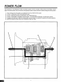
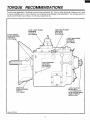
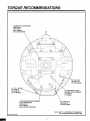
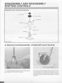
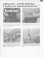
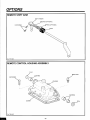
1
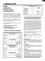
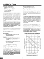
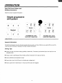
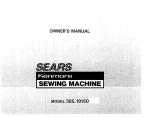
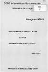
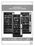
Service Manual
Fuller Mid-Range Transmissions
TRSM0130
October 2007
FS-4005A
FS-4005B
FS-4005C
FS-4205A
FS-4205B
FS-4205C
FS-5005A
FS-5005B
FS-5005C
For parts or service call us
Pro Gear & Transmission, Inc.
1 (877) 776-4600
(407) 872-1901
[email protected]
906 W. Gore St.
Orlando, FL 32805
A WARNING
Before starting a vehicle always be
seated in the drivers seat, place the
transmission in neutral, set the parking brakes and disengage the clutch.
Before working on a vehicle place the
transmission in neutral, set the parking brakes and block the wheels.
Before towing the vehicle place the
transmission in neutral, and lift the
rear wheels off the ground or disconnect the driveline to avoid damage to
the transmission during towing.
TABLE OF CONTENTS
FOREWORD ................................................................2
MODEL DESIGNATIONS AND SPECIFICATIONS ..................................3
LUBRICATION ...............................................................4
OPERATION ................................................................6
POWER FLOW ...............................................................7
TORQUE RECOMMENDATIONS ................................................8
PREVENTIVE MAINTENANCE .................................................10
PRECAUTIONS
DISASSEMBLY ............................................................12
INSPECTION ..............................................................12
REASSEMBLY .............................................................14
DISASSEMBLY AND REASSEMBLY - SHIFTING CONTROLS
GEARSHIFT LEVER HOUSING ASSEMBLY ....................................... 15
SHIFT BAR HOUSING ASSEMBLY ..............................................18
REMOVAL - YOKE AND CLUTCH HOUSING .....................................27
DISASSEMBLY -TRANSMISSION .............................................. 29
REASSEMBLY - TRANSMISSION ..............................................43
INSTALLATION- CLUTCH HOUSING ........................................... 57
INSTALLATION - SHIFTING CONTROLS ........................................58
OPTIONS ..................................................................59
FOREWORD
This manual is designed to provide detailed information
necessary to service and repair the Eaton@ Fuller@
Transmission listed on the cover.
As outlined in the Table of Contents, the manual is
divided into 3 main sections:
a. Technical information and reference
b. Removal, disassembly, reassembly, and
installation
c. Options
The format of the manual is designed to be followed in
its entirety if complete disassembly and reassembly of
the transmission is necessary. But if only one component of the transmission needs to be repaired, see the
Table of Contents for the page numbers showing that
component. For example, if you need to work on the
Shifting Controls, you will find instructions for removal,
disassembly, and reassembly on page 15. Instructions
for installation are on page 58. Service Manuals,
Illustrated Parts Lists, Drivers Instructions, and other
forms of product service information for these and other
Eaton Fuller Transmissions are available upon request. A Product Literature Order Form, Service
Bulletins (detailing information on product improvements), repair procedures, and other service-related
subjects can be obtained by writing to the following
address:
EATON CORPORATION
TRANSMISSION DIVISION
Technical Service Department
P.O. Box 4013
Kalamazoo, Michigan 49003
(616) 342-3344
Every effort has been made to ensure the accuracy of all information in this brochure. However, Eaton Transmission Division makes no expressed or implied warranty or representation based on the enclosed information.
Any errors or omissions may be reported to Training and Publications, Eaton Transmission Division, P.O. Box 4013,
Kalamazoo, Ml 49003.
2
MODEL DESIGNATIONS
AND SPECIFICATIONS
Nomenclature:
F S- 5005A
Letter Designations
Number Designations
I
Ratio Group
I
Fuller"'
Forward Speeds
Design Level
Synchronized----------""""'
=
x 100 Nominal Torque
Capacity
IMPORTANT: All Eaton Fuller Transmissions are
identified by the model and serial number. This
information is stamped on the transmission identification tag and affixed to the case.
DO NOT REMOVE OR DESTROY THE TRANSMISSION IDENTIFICATION TAG.
Specifications:
Reial ve Soeed
PTO 3ear:::
lnpc: R.P.~A.
GearRat'os
Note S
Q,I Caoaci:y
Pi-ts
'"1:'1)
~ote 2
l//eo':
Los.
:Kg)
No:c ·
_e-g111
ir.
Model
Ne.
Speecs
1 st
FS-5005A
5
7.52
2.54
2.54
1.52
1.00
6.27
.460
.435
21.9
(556.0)
280
(127.0)
10.5
(5.0}
FS-50058
5
6.82
2.15
2.15
1.28
1.00
5.30
.543
.515
280
(127.0}
10.5
(5.0)
FS-5005C
5
6.82
1.99
1.99
1.17
1.00
5.30
.543
.515
21.9
(556.0)
21.9
(556.0)
280
(127.0)
10.5
(5.0}
2 nc
3 ·a
4th
5 '.1
Rf:'ver:;e
Rig rt
Li:/t
1Uersi
1. Lengths measured from clutch housing face to speedo gear rear.
2. Weights include shift bar housing, clutch housing, less tower assembly, and clutch release parts. For more
information on available clutch housings, see the transmission's Illustrated Parts List or the Super Parts Book.
All weights are approximate.
3. Oil capacities are approximate, depending on inclination of engine and transmission. Always fill transmission,
with proper grade and type of lubricant, to level of filler opening. See LUBRICATION.
3
-
LUBRICATION
Proper
Lubrication . ..
the Key to long
transmission life
Recommended Lubricants
Type
Eaton@Roadranger(<,
CDSO Transmission
Fluid
Heavy Duly E. .gine Oi
MIL-L-21048, C or Dor
APl-SF 0' AP:-CD
Grade
(SAE)
50
Fahrenheit (Celsius)
Ambient
Temperature
All
0
(Pr9ViOJS API
des1gna~io1s
50
40
30
Above 10' F (-t2'C)
Above 10"F (·12"C;
Below 10'F :-12''C)
90
Abo'e 1 JF i- '.2'·C)
Below 'O'F i-"2'C)
acceotab e1
Mneral Gear OI' w'.h rust
and oxi:::a~ion i'":hibitor
ft.Pl-GL-'.
Proper lubrication procedures are the key to a good allaround maintenance program. If the oil is not doing its
job, or if the oil level is ignored, all the maintenance
procedures in the world are not going to keep the
transmission running or assure long transmission life.
The use of mild EP gear oil or multi-purpose gear oil
is not recommended, but ifthesegearoilsare used,
be sure to adhere to the following limitations.
Eaton Fuller Transmissions are designed so that the
internal parts operate in an oil circulating bath by the
motion of the gears and shafts.
Do not use mild EP gear oil or multi-purpose gear oil
when operating temperatures are above 230° F (110"
C). Many of these gear oils, particularly 85W140,
break down above 230° F and coat seals, bearings, and
gears with deposits that can cause premature failures.
If these deposits are observed (especially a coating on
seal areas causing oil leakage), change to Eaton
Roadranger CD50 transmission fluid, heavy duty engine oil, or mineral gear oil to assure maximum component life and to maintain your warranty with Eaton.
(Also see "Operating Temperatures".)
Thus, all parts are amply lubricated if these procedures
are closely followed:
1.
2.
3.
4.
Maintain oil level. Inspect regularly.
Change oil regularly.
Use the correct grade and type of oil.
Buy from a reputable dealer.
Lubrication Change and Inspection
Additives and friction modifiers are not recommended
for use in Eaton Fuller Transmissions.
Eaton® Roadranger® CDSO Transmission Fluid
HIGHWAY USE
Firs' 3,000 tc 5,000 miles
{4827 to 8045 Km!
Proper Oil Level
Factory fill
1rn:ia o·ai:-:.
Every t 0,000 miles
(;6090 Ker)
Check flukl level.
Check ::::r iea;.;s.
Craoge t•ans'.'1•sso1
llu·d.
Every 250,000 m•les
(402336 Krr)
Proper Oil Level
OFF-HIGHWAY USE
Firs~
Make sure oil is level with the filler opening. Because you
can reach oil with your finger does not mean oil is at
proper level. (One inch of oil level is about one gallon
of oil.)
Factory f I
initial d·ain.
30 hour_;
Every 40 hours
lnspec: fluic eve!. Creek fa• leaks.
Criange tra."sriission 71uic where
severe dirt :::onditions exist.
Cra1ge trans11·ss.0° lluid
(Norrra: off-h ahway cse."
Every 500 hours
Every t .:O·J oours
Draining Oil
Heavy Duty Engine Lubricant or
Mineral Gear Lubricant
Drain transmission while oil is warm. To drain oil remove
the drain plug at case bottom. Clean the drain plug
before re-installing.
HIGHWAY USE
First 3.000 to 5,COO riiles
I4827 to 8045 Krr I
Fac:oryiill
imtial.
Every 10,000 -;iles
(t6090 ~rr•
l'isoec: lubrica'lt level.
C1eck :or ·eal{s.
Every 50.000 11 les
(80450)
Cha1ge tra:isr:i1ss1on
lubr•car:.
Refilling
Clean case around filler plug and remove plug from case
side. Fill the transmission to the level of the filler opening.
If the transmission has two filler openings, fill to the level
of both openings.
The exact amount of oil depends on the transmission
inclination and model. Do not over fill-this causes oil to
be forced out of the case through the front bearing cover.
When adding oil, types and brands of oil should not
be mixed because of possible incompatibility.
OFF-HIGHWAY USE
Cnange transrr:issio-;
lubricant en new :.inits.
First 3·J oours
Every 40 1purs
Every 500 rours
Every 1,00C hoers
sew
lr.soect lubricaPt
1
eve~.
Chee!\ br 1eaks.
c~.a:ige
transmissior. lubr:cant where
sevee di~ condit:ons exist.
Change 'ransmission lubricant
(Norma: off-h:ghway t.se.]
4
LUBRICATION
Operating Temperatures
-With Eaton Roadranger
CDSO Transmission Fluid
Heavy Duty Engine Oil
and Mineral Oil
Proper Lubrication Levels
as Related to Transmission
Operating Angles
If the transmission operating angle is more than 12
degrees, improper lubrication can occur. The operating angle is the transmission mounting angle in the
chassis plus the percent of upgrade (expressed in
degrees).
The transmission should not be operated consistently
at temperatures above 250° F (120° C}. However,
intermittent operating temperatures to 300° F (149° C}
do not harm the transmission. Operating temperatures
above 250° F increase the lubricant's oxidation rate
and shorten its effective life. When the average operating temperature is above 250° F, the transmission
can require more frequent oil changes or external
cooling.
The chart below illustrates the safe percent of upgrade
on which the transmission can be used with various
chassis mounting angles. For example: if you have a
4 degree transmission mounting angle, then 8 degrees
(or 14 percent of grade) is equal to the limit of 12
degrees. If you have a 0 degree mounting angle, the
transmission can be operated on a 12 degree (21
percent} grade.
The following conditions in any combination can cause
operating temperatures of over 250° F: (1 )operating
consistently at slow speeds, (2) high ambient temperatures, (3) restricted air flow around transmission, (4)
exhaust system too close to transmission, (5) high
horsepower, overdrive operation.
Anytime the transmission operating angle or 12 degrees is exceeded for an extended period of time the
transmission should be equpped with an oil pump or
cooler kit to insure proper lubrication.
External oil coolers are available to reduce operating
temperatures when the above conditions are encountered.
Note on the chart the effect low oil levels can have on
safe operating angles. Allowing the oil level to fall 1/2"
below the filler plug hole reduces the degree of grade
by approximately 3 degrees (5.5 percent}.
Transmission Oil Coolers are:
Proper Lubrication Levels are Essential!
Recommended
-With engines of 350 H.P. and above with
overdrive transmissions
Required
-With engines 399 H.P. and above with over
drive transmissions and GCW's over
90,000 lbs.
-With engines 399 H.P. and above and 1400
lbs-ft or greater torque
-With engines 450 H.P. and above
With EP or Multipurpose Gear Oil
Mild EP gear oil and multipurpose gear oil are not
recommended when lubricant operating temperatures
are above 230° F (110° C). In addition, transmission oil
coolers are not recommended with these gear oils
since the oil cooler materials can be attacked by these
gear oils. The lower temperature limit and oil cooler
restriction with these gear oils generally limit their
success to milder applications.
2 t---+--l--+--+--l---1---1 1 8'
0
0
0
2
3
4
5
67
Transmission Mounting Angle
Dotted line showing "2 Quarts Low" is for
reference only. Not recommended
5
OPERATION
Gear Shift Lever Pattern and
Shifting Instructions
Follow the simple 5-speed shift pattern. ..
Simple progressive
shift pattern
-,\
"-·-1
/
\,__..
I
I
__)
I
\,
Neutral
-,
I .,
3
1
J
··--"
i
4
2
R
-,
(--
/
____
I
(
j
\ ..____
R
<__;
\... I ./
-
Ne~tral
_ /j
] ___
1
-
'
\
2H•
2L i
1H .,,
1L ,
. ,;
--j
1(-3H -,i ,-- s -,I
\__ __) "·-
1
4H
4L ,
3L
·
: <_ _;
R
\, _ _ )
(--\
I
I 2H.
4H'
: 4L
2L
I
""-
_)
:
(,,.-
·-,,
(--
, 1H ,
1L
\,_
__/
-1
\.._.)
~- Neutral
/-~\
.\
I
-..\
3H , , SH
\
3L
___ _.) ,__
j
SL !
-
5
. /J
FS-SOOSB with "soft"
fourth and 2-speed axle.
FS-5005C with "short"
fourth and 2-speed axle.
Adobe 0001-2/88
General Information
FS-5005 transmissions have five forward speeds and one reverse, and are shifted as you would shift any synchronized manual transmission, following the simple 5-speed shift pattern.
Driving Tips
•
Always use the clutch when making upshifts or downshifts. Premature synchronizer failure can result from not
using the clutch.
•
Always select a starting gear that provides sufficient reduction for the load and terrian.
•
Never downshift at road speed too high.
•
Never slam or jerk the shift lever to complete gear engagement.
•
Never coast with the transmission in neutral and the clutch dis-engaged.
6
POWER FLOW
The transmission must efficiently transfer the engine's power, in terms of torque, to the vehicle's rear wheels. Knowledge of whattakes place in the transmission during torque transfer is essential when troubleshooting and making repairs.
1.
2.
3.
4.
5.
6.
Power (torque) from the engine is transferred to the input shaft and drive gear.
Torque is transferred to the countershaft drive gear.
Torque is delivered along the countershaft to all countershaft gears.
Torque is transferred to "engaged" mains haft gear. The cross section illustrates 1st speed gear position.
Engaged mainshaft gear internal clutching teeth transfers torque to mainshaft through synchronizer assembly.
Mainshaft transfers torque directly to driveshaft through rear yoke.
1.
5.
3.
4.
7
TORQUE RECOMMENDATIONS
Correct torque application is important to assure long transmission life. Over or under tightening of fasteners can resul1
in a loose installation and, in many instances, can eventually cause damage to the transmission. Use a torque wrench to
obtain recommended torque ratings. Do not torque capscrews dry.
4 FRONT BEARING
COVER CAPSCREWS
15-20 LBS.-FT.
5/16-18 THREAD
9 SHIFT RAIL RETAINER
CAPSCREWS
20-25 LBS.-FT.
3/8-16 THREAD
4 SHIFT LEVER HOUSING
CAPSCREWS
20-25 LBS.-FT.
3/8-16 THREAD
17 SHIFT BAR HOUSING
CAPSCREWS
20-25 LBS.-FT.
3/8-16 THREAD
@
4 CLUTCH HOUSING
CAPSCREWS
145-155 LBS.-FT.
5/8-16 THREAD
2 HAND HOLE
COVER CAPSCREWS
5 LBS.-FT.
1/4-12 THREAD
OUTPUT SHAFT NUT
300-350 LBS.-FT.
11/4-18 THREAD WITH
NYLON LOCKING INSERT
(OILED AT VEHICLE
INSTALLATION)
Adobe 0002-2/88
8
TORQUE RECOMMENDATIONS
4 MAINSHAFT REAR BEARING
COVER NUTS
60-70 LBS.-FT.
1/2-32 THREAD
USE LOCKWASHERS
OIL FILL PLUG
20-25 LBS.-FT.
3/4 PIPE THREAD
14 PTO COVER
CAPSCREWS
10-15 LBS.-FT.
3/8-16 THREADS
2 COUNTERSHAFT REAR
BEARING CAP SET SCREWS
5-10 LBS.-FT.
1/4 THREAD
4 COUTNERSHAFT REAR BEARING
COVER CAPSCREWS
20-30 LBS.-FT.
3/8-16 THREAD
USE PLAIN FLAT WASHERS
OIL DRAIN PLUG
20-25 LBS.-FT.
3/4 PIPE THREAD
NOTE: APPLY LOCTITE #262 TO THREADS OF
ALL CAPSCREWS BEFORE INSTALLING.
Adobe 0003-2/88
9
PREVENTIVE MAINTENANCE
10
PREVENTIVE MAINTENANCE
Preventive Maintenance Check Chart
CHECKS WITHOUT PARTIAL
DISASSEMBLY OF CHASSIS OR CAB
8. Gear Shift Lever Housing Assembly
1. Clutch Housing Mounting
a. Remove the gear shift lever housing assembly from transmission.
b. Check tension spring and washer for set
and wear.
c. Check gear shift lever bottom end for wear of
slots. Also check finger assembly for wear.
a. Check all capscrews of clutch housing flange
for looseness.
2. Clutch Release Bearing (Not Shown)
a. Remove hand hole cover and check radial
and axial clearance in release bearing.
b. Check relative position of thrust surface of
release bearing with thrust sleeve on pushtype clutches.
CHECKS WITH DRIVE LINE DROPPED
9. Universal Joint Companion Flange or
Yoke Nut
3. Clutch Pedal Shaft and Bores
a. Pry upward on shafts to check wear.
b. If excessive movement is found, remove
clutch release mechanism and check bushings in bores and wear on shafts.
a. Check for tightness. Tighten to recommended torque rating.
10. Output Shaft (Not Shown)
a. Pry upward against output shaft to check
radial clearance in mainshaft rear bearing.
4. Lubricant
a. Change at specified service intervals.
b. Use only the types and grades as recommended. See LUBRICATION.
CHECKS WITH UNIVERSAL JOINT COMPANION FLANGE OR YOKE REMOVED
5. Filler and Drain Plugs
a. Remove filler plug and check level of lubricant
at specified intervals. Tighten filler and drain
plugs securely.
NOTE: If necessary, use solvent and shop rag to
clean sealing surface of companion flange or
yoke. DO NOT USE CROCUS CLOTH,
EMERY PAPER, OR OTHER ABRASIVE
MATERIALS THAT WILL MAR SURFACE
FINISH.
6. Capscrews and Gaskets
a. Check all capscrews, especially those on
PTO covers, front and rear bearing covers for
looseness which can cause oil leakage.
See TORQUE RECOMMENDATIONS.
b. Check PTO opening and rear bearing covers
for oil leakage.
11. Splines on Output Shaft (Not Shown)
a. Check for wear from movement and chucking
action of the universal joint companion flange
or yoke.
7. Gear Shift Lever
12. Mainshaft Rear Bearing Cover
a. Check for looseness and free play in housing. If lever is loose in housing, proceed with
Check No. 8.
a. Check oil seal for wear.
11
-
PRECAUTIONS
Disassembly
It is assumed in the detailed assembly instructions that the lubricant has been drained from the transmission, the
necessary linkage disconnected and the transmission has been removed from vehicle chassis. Removal of the gear shift
lever housing assembly is included in the detailed instructions (Disassembly and Reassembly-Shifting Controls);
however, this assembly must be detached from shift bar housing before transmission can be removed.
FOLLOW CLOSELY EACH PROCEDURE IN THE DETAILED INSTRUCTIONS, MAKING USE OF THE TEXT,
ILLUSTRATIONS, AND PHOTOGRAPHS PROVIDED.
4. CLEANLINESS-Provide a clean place to work.
It is important that no dirt or foreign material
enters the unit during repairs. Dirt is an abrasive
and can damage bearings. It is always good
practice to clean the outside of the unit before
starting the planned disassembly.
1. BEARINGS-Carefully wash and relubricate all
reuseable bearings as removed and protectively
wrapped until ready for use. Remove bearings
planned to be reused with pullers designed for
this purpose.
2. ASSEMBLIES-When disassembling the various
assemblies, such as the mainshaft, countershafts, and shift bar housing, lay all parts on a
clean bench in the same order as removed. This
procedure simplifies reassembly and reduces the
possibility of losing parts.
5. WHEN USING TOOLS TO MOVE PARTSAlways apply force to shafts, housings, etc, with
restraint. Movement of some parts is restricted.
Never apply force to the part being driven after it
stops solidly. The use of soft hammers, bar, and
mauls for all disassembly work is recommended.
3. SNAP RINGS-Remove snap rings with pliers
designed for this purpose. Snap rings removed
in this manner can be reused, if they are not
sprung or loose.
Inspection
Before reassembling the transmission, check each part carefully for abnormal or excessive wear and damage to
determine reuse or replacement. When replacement is necessary, use only genuine Eaton Fuller Transmission parts
to assure continued performance and extended lite from your unit.
Since the cost of a new part is generally a small fraction of the total cost of downtime and labor, avoid reusing a
questionable part which could lead to additional repairs and expense soon after reassembly. To aid in determining the
reuse or replacement of any transmission part, consideration should also be given to the unit's history, mileage,
application, etc.
Recommended inspection procedures are provided in the following checklist.
B. GEARS
A. BEARINGS
1. Wash all bearings in clean solvent. Check balls,
rollers, and raceways for pitting, discoloration,
and spalled areas. Replace bearings that are
pitted, discolored, spalled, or damaged during
disassembly.
1. Check gear teeth for frosting and pitting. Frosting of gear teeth faces present no threat of
transmission failure. Often in continued operation of the unit, frosted gears "heal" and do not
progress to the pitting stage. In most cases,
gears with light to moderate pitted teeth have
considerable gear life remaining and can be
reused, but gears with advanced stage pitting
should be replaced.
2. Lubricate bearings that are not pitted, discolored, or spalled and check for axial and radial
clearances.
Replace bearings with excessive clearances.
2. Check for gears with clutching teeth abnormally
worn, tapered, or reduced in length from clashing in shifting. Replace gears found in any of
these conditions.
3. Check bearing fit. Bearing inner races should
be tight to shaft; outer races slightly tight to
slightly loose in case bore. If bearing spins
freely in bore, case should be replaced.
12
PRECAUTIONS
Inspection (cont.)
I. GEAR SHIFT LEVER HOUSING ASSEMBLY
3. Check axial clearance of gears. Where excessive clearance is found, check gear snap ring,
split washer, clutch hub, and gear hub for excessive wear.
1. Check spring tension on shift lever. Replace
tension spring if lever moves too freely.
2. If housing is disassembled, check gear shift
C. SPLINES
lever bottom end and shift finger assembly for
wear. Replace both gears if excessively worn.
1. Check splines on all shafts for abnormal wear.
If sliding clutch gears, companion flange, or
clutch hub have worn into the sides of the
splines, replace the specific shaft affected.
J. BEARING COVERS
1. Check covers for wear from thrust of adjacent
bearing. Replace covers damaged from thrust
of bearing outer race.
D. WASHERS
1. Check surfaces of all washers. Washers
scored or reduced in thickness should be
replaced.
2. Check cover bores for wear. Replace those
worn oversized.
K. OIL SEALS
E. REVERSE IDLER GEAR ASSEMBLIES
1. Check oil seal in input shaft and rear bearing
cover. It sealing action of lip has been destroyed, replace seal.
1. Check for excessive wear from action of roller
bearings.
F. GRAY IRON PARTS
L.
1. Check all gray iron parts tor cracks and breaks.
Replace or repair parts found to be damaged.
Heavy castings may be welded or brazed provided the cracks do not extend into the bearing
bores or bolting surfaces. When welding, never
place the ground so current passes through the
transmission.
SYNCHRON~ERASSEMBLY
1. Check synchronizer for burrs, uneven and
excessive wear at contact surface, and metal
particles.
2. Check blocker pins for excessive wear or looseness.
3. Check synchronizer contact surfaces on the
synchronizer cups for wear.
G. CLUTCH RELEASE PARTS
1. Check clutch release parts. Replace yokes
worn at cam surfaces and bearing carrier worn
at contact pads.
2. Check pedal shafts. Replace those worn at
bushing surfaces.
H. SHIFT BAR HOUSING ASSEMBLY
1. Check tor wear on shift yokes and finger as
sembly at pads and lever slot. Replace excessively worn parts.
2. Check yokes for correct alignment. Replace
sprung yokes.
3. Check lockscrews in yoke assembly retainer
plates. Tighten those loose.
13
-
PRECAUTIONS
Reassembly
Make sure that case interiors and housings are clean. It is important that dirt and other foreign materials are kept out
of the transmission during reassembly. Dirt is an abrasive and can damage polished surfaces of bearings and washers.
Use certain precautions, as listed below, during reassembly.
5. INITIAL LUBRICATION-Coat all thrust washers,
synchronizers, and bearings with transmission
lubricant during reassembly to prevent damage
during initial start up.
1. GASKETS-Use new gaskets throughout the
transmission as it is being rebuilt. Make sure all
gaskets are installed. An omission of any gasket
can result in oil leakage or misalignment of
bearing covers.
6. AXIAL CLEARANCES-Maintain original axial
clearances for mainshaft gears.
2. CAPSCREWS-To prevent oil leakage and
loosening, use Loctite #262 thread sealant on all
capscrews. For recommended torque ratings,
see TORQUE RECOMMENDATIONS.
7. BEARINGS-Using a sleeve type driver that
contacts the bearing inner race prevents damage
to the rollers and cage.
3. SHIMS-Apply a light coat of Loctite 51 O to both
sides of shims before final installation to prevent
leakage.
8. UNIVERSAL JOINT COMPANION FLANGE OR
YOKE-Pull the companion flange or yoke into
place with the output shaft nut, using 300-350
lbs.-ft. (407-475 Nm) of torque. Make sure the
speed ometer drive gear or a replacement spacer
has been installed. Failure to properly torque the
nut can result in damage to the mainshaft rear
bearing.
4. ASSEMBLY-See the illustrations provided in the
detailed disassembly instructions as a guide to
reassembly.
IMPORTANT: SEE THE APPROPRIATE ILLUSTRATED PARTS LIST (SPECIFIED BY MODEL SERIES) TO
ENSURE THAT PROPER PARTS ARE USED DURING REASSEMBLY OF THE TRANSMISSION.
14
DISASSEMBLY AND REASSEMBLY
SHIFTING CONTROLS
Gearshift Lever Housing Assembly
LCV(RGAl=P,---·
9 - - -ousrcovrR
~CAPSCREVi
HOUSING
~
,,...,,,,
):t-
PIN
y
_PIN
"SHJFT LEVE.A
WAS"ER~
~PRING
GAS!<H~
A. Removal and Disassembly of Gearshift Lever Housing
...
2. Remove the shifl levergripand boo1 from the shift lever,
sorure assmbly In a vise with the housing bottom up. Use
a large scrc·wdriver to twisi between spnrig and houSJng,
forongthe Spl'ing from under tne llovsing lugs-. Dooneooi
1. Twn ou1 tCMJr capsctews arld remove the tower a5Sembly and gasket from the shllt bar hous.ing
a1 a lime.
15
I
DISASSEMBLY AND REASSEMBLY
SHIFTING CONTROLS
Gearshift Lever Housing Assembly (cont.)
(
3. Removo tho ten&1on spring trom the haualng
5. Remove the spadO pins lrom housing bo1e.
4, Remove tne wasf'le( and gearshtl\ ..ver trom ttle
houM'lg Remove the boot from die gear 1htfl IGVlf
16
a
DISASSEMBLY AND REASSEMBLY
SHIFTING CONTROLS
B. Reassembly of Gearshift Lever Housing Assembly
3. Use a spMg driving tool to Install tho tension sp<ing
under the housing lugs, seating one ooll at a ume
1. Secure 1he gearshift lever housing In a vise, Install the
spade pins in housing bore.
4. Remove ass9'mbty lrom lhe vise and tnstaJI lhe rubbe<
2. POSihon gearshlh lever In housing with the spade pins
in 1ho levor ball slot and ins1all the lension spnng washer
boot ovEK the gearshlJt klver -and against tt1<I housing,
lnsl.all 1he shrf1 lev9I gn.p.
over tho ball .dlslled side up
17
DISASSEMBLY AND REASSEMBLY
SHIFTING CONTROLS
hift Bar Housing Assembly
..
DISASSEMBLY AND REASSEMBLY
SHIFTING CONTROLS
C. Removal and Disassembly of Shift Bar Housing
.
'
'
t '
I
-
1. Sh 11100 transmission into neutral po81hon, remove the
capscrewa. and I It the shift bar housing and OdSklll honl
3. Rcmo11e tile r8$1 of 1he capsorewS: and tne two retain
ors.
11'\c oate (1rigtHI.
2. Uy h ""111>11' ~onlhe,...... _
-·
MO capecr9W$ a.s showo and shh 4th·~ )'Ok.o 1:111 n:itf
into .&th speed position W'trl a $C~Nvr
19
DISASSEMBLY AND REASSEMBLY
SHIFTING CONTROLS
Shift Bar Housing Disassembly (cont.)
7. If neoossary remove tho front spacer from 1st-1evetse
shdt baf'
5. Remove 2nd-3rd yoke assembly and lnteflock pin
(Inset).
RQ1~\ove lhe 1st·reverse lock p10 from Iha 1st-reverse
shift yoke tISsembly Remove the 1st reverso shift yoke
6. Rernove 1SJ•toverso bar assembly II neoessary
remove the front spaoer from 1st-reverse shift bar (ln$el).
8.
0
(1nsel).
20
DISASSEMBLY AND REASSEMBLY
SHIFTING CONTROLS
Shift Bar Housing Disassembly (cont.)
,
'
r
9. Remove lhe
tst-~verae
actua1or
11. Remove 1he revetse plu:noer reta.intng plug and ga.Ske:t
from 1he shift bar housing
1O. Remove tile four interlockballs.1halhf'eedeten1balls.
100 ltlrce back up liQht swnch bafls, and the 1.hree springs
trom the shltc bar hou-.sing.
12. Remove the reverse plunger spring.
DISASSEMBLY AND REASSEMBLY
SHIFTING CONTROLS
Shift Bar Housing Disassembly (cont.)
•
13. Remove 1he reverse p1u~er s1op
15. II the yokej)OO~ nre tObe repl;ieed, remove worn pnd
trom sh1t1 yOke 1n.s1:ill now p.'dandbend tabG. over top and
bottom 01 yOke
164 I' necess.ary itllft bll)Cll.S and shift yokes ca.., be
removed bydr1vi1"1Q IOCkp.n from sh f1 bar with a punch aod
hammer as shown
22
DISASSEMBLY AND REASSEMBLY
SHIFTING CONTROLS
D. Reassembly of Shift Bar Housing
3. InstaD !he 1ev~so ptungorgaske1 ancf plug Tighteo lhO
reverse plunger plug 10 11101ecommended tCKq1,1e
1. Pillot tho shift bar housing on 1tr side as shOwn ond
1ns11.1U 1ho rovo1so plunger.
- """"""-
2. 1ns1o1 .,. ,...,... ~"II"' -
r.-i
ll>d ,,,.
4. If shdt block$ or st 1fl yok• were removed ahgn sh 11
yoke or b6ock with 01.gnment holo 1n the shrl't bar end inaer1
klck P'"
NOTE: II p11MOUsly IQl'l'IOVOd install two spacers on 1$l·
teverse sh1h 1>a1 before •nstotllng both shift blocks (inse-11.
23
DISASSEMBLY AND REASSEMBLY
SHIFTING CONTROLS
Shift Bar Housing Assembly (cont.)
s. Install intoOOck bails, deten1 balls and springs in the
following seQUence; position ~3) balls in the reverse bght
swrleh oore and instaJl 1s1-reversedetentspnngand ball.
?OStbOn (2) balls In adjacent cross bore and install 2nd·
3rd detent spring and ball Position (2>balls ui adjacent
cross bore and install 4th~51h deten1 spnr.g and ball
NOTE: Salls and SJ)llngs can be used lnterohangeabl)'.
6. Seal the 1st rQVQrse actuatOf In the sh1h bar housing,
over 1he actuator pll/01 ptn, as shown
7. POStbon tst·reverse yoke assembly in dle shift bar
housing (inset) Install the 1st-reverse lock pin in the yoke
assembly.
DISASSEMBLY AND REASSEMBLY
SHIFTING CONTROLS
Shift Bar Housing Assembly (cont.)
8. Position 151-tev~rse bat assambfy in mo hous.ng as·
sembty as shown.
NOTE: Position spacQrs as shOwn
-- --
1O. Position 1he 4th·5th yoke assembly in lhe hovslng
assembly as shown.
'
9. ln!lalt the 2nd·3rct yoke assembly interlock pin (1ose1~.
POSlbon the 2nd-3rd yoke assembly ln the housing ass.em·
bly as shown
11. Place lhe still! yokes an oou11at and Install the 1wo
retainers atld lhe tout capscrews as sllO•llfl Tigh1on the
e.apsaews 10100 recommenced tOtQUB. Shih 4th·Sth yoke
as&&mbfy into 4tll speed pos111on.
DISASSEMBLY AND REASSEMBLY
SHIFTING CONTROLS
Shift Bar Housing Assembly (cont.)
12. lns1au lhe remaln1ng rwo capscrews nnd tighten
capsc1&w1 10 1ooommcnded 1orque
REMOVAL - YOKE AND CLUTCH HOUSING
Yoke and Clutch Housing
0
....
,,.;_
~ kA~fl !Of: COVE-A
1.0C~A
~w
••
A. Removal of Yoke
:z.
1. Lock 1he 11ansrn.r.s1on by oogaglng lwo mi\lnMnl1geat&
as Shown (111&00. Use a latge b<oakCf bar 10 tutn 1he
rc1a!n ng nul from lhe output shaft
v
Removo !he yoko from 1he output shalt.
REMOVAL - YOKE AND CLUTCH HOUSING
B. Removal of the Clutch Housing
1. Remove lhe four retaining bOlts as sh<>wn.
2• .kir clutch houslng \\/Ith a rubber mal'6l and pul1 lrom the
transmission case.
28
DISASSEMBLY - TRANSMISSION
Input Shatt Assembly
INPUT SHArT ANO DRJVE GEAR
BeAfl:lNG CUP
A. Removal & Disassembly of Input Shaft Assembly
....,
2. Remove I.he input shaft assembly from the transmls·
1. Remove ltle four capscrews trom lhe front bearing
oover a.nd remove 1he cover and shims The tront beanng
oovershlms can come oft \Vlth 1he front bean.ng cover. If
necessary remove the oi1 seal from the cover (inset).
29
DISASSEMBLY - TRANSMISSION
Input Shaft Disassembly (cont.)
3. It nectSSatY. remDVe me ratan!Joo snap r.ng Mel the
beaung rtltntion ring
5. use a c:hisef lO remove the beamg cage and rollers
Ins.tall beanng puster anct remoye the bearing race lrom N
...,.,. shalt.
4, It neoeuary temove the 1.a roller bearings tron1 tna
ma.n drive gear bearing poc:f(et
30
DISASSEMBLY - TRANSMISSION
Malnshaft Assembly
c tH !>IH S:YNCl~llfl1
ASS£t.•Bl..V
'""""""'"'"'
""" '>..
'-...
'IMAIA:l •ARI~~
"\
, I~ASHER"'"""'
......
COii<
...
~ruo
OfAA
c.. ....
B. Removal and Disassembly of Mainshaft
2. Remove speedon'lelerdrNe gear (inset). Tap on 1ne
tron1 ol Ille main Iha~ 10 ,,_. U'8 ma.nsha~ ,..._d
abou! 1 4" UM pry bwa to t8"nCri9 lh& rear beanng a.,
a>d locoong """'mg
1. Rffmovt the toor rcta1ntng nuts and kx:kw~hers and
remove the '9at beardlQ rove.- It R808INI')'. t8"T10Y91he
Oii i;.1181 lrom covet ("5e!J
31
DISASSEMBLY - TRANSMISSION
Mainshaft Disassembly {cont.)
3. Wrap a S'l1ng or rope around the 2nd-3rd S)'OChronlzer
Use a hotst to remove the mainsllaft assembly from the
transmtSslon case
S. Remove the throst bearing and bearing race.
4. Install the malnshaft assembly in a vise equipped m lh
soh )aws or wood, shah lronl facing up. Remove !ht! 4th-
6. RemO\l'e 41h-51h speed clutch hub.
51h speed synchronizer and wps.
32
DISASSEMBLY - TRANSMISSION
Mainshatt Disassembly (cont.)
-
7. Remove the 4th spaoo geaf
a. Remove 4ltl geru bearing
9. Remove 3rd speed gear retaining snap ring.
10. Aen1ove 31d speed gea11hrusl wasllor. Remove the
locating ball.
DISASSEMBLY - TRANSMISSION
Mainshaft Disassembly (cont.)
11. Remove 1he lid speQd g.ear
13. Remove lhe 3rd gear synchronizer cup and synehrO·
!lizer assembly,
12. Remove the 3rd gear beanng.
14. Reposition ma.inshalt In Lhevlse so reat beating is up
DISASSEMBLY - TRANSMISSION
Malnshafl Disassembly (cont.)
15 U8'llg • g90r ouller. remove lhl"'"""""" ,..,
17. RemoYethelll-ip14washer
bW"ll•"-'
18. Remov& thO 1S.I gea1 Use cavtjon so n01 10 IDM
beanng rOllors ..-lho ,., gear(.,...).
DISASSEMBLY - TRANSMISSION
Malnshaft Disassembly (cont.)
19. Remove 1.he beanng rollers and spacers.
21 . Remove the 1si-1everse sliding clu1ch
20. Remove 1s1-reverse sluf1 hvbsnap ring.
22. Remove dte shih hub.
36
DISASSEMBLY - TRANSMISSION
Mainshaft Disassembly (cont.)
23. Remove the reverse gear
25. Remove 2nd gear split washer retainer ring
24. Remove the rBWrSe gear beanng
26. Remove lh& 2nd gear spl I washer and locaung bail
jmse1)
37
DISASSEMBLY - TRANSMISSION
Mainshaft Disassembly (cont.)
27. - . 2l'ld speed gear
311
DISASSEMBLY - TRANSMISSION
ountershaft Assembly
Reverse Idler Assembly
o..EACE.AR
.
-
CUI ISJn t111
C. Removal and Disassembly of Countershaft and Reverse
Idler
1. Romovt the lour cac:iwews and Lhe counlerthah rear
i.aring oover and gaskel
2. Remove the 1wo ROI screws (1fls&1}. Remove 1he
beanng reta nor oult-r race. and shims
NOTE: Countllrsl\llft may i.hde to the rear aoo ou1 oi mo
beanng bolt
DISASSEMBLY - TRANSMISSION
3. Movo the coun1ershatt assembly to the rear ~nd 1111ti
from the transmission case.
5. Using a wedge bar, remove the roverse idler shaft.
4. Remove 1ho <averse l~r retaining capscrew and the
retainer
6. Remove the tevers& Idiot bearings. spacer. and
thrust washers.
•o
DISASSEMBLY - TRANSMISSION
7. It the countofShah tront bearing raoe is to be replaced
dnve ltl& bofe plug through the #ron1 of the transmlsslson
and dr1ve 1he race to the reartoWard the case's insrde.
9. U$9 a screwdriver and snap ring pilers to move the snap
ring out ot snap rlng groove and against Iha beanng back.
•
8. Position gear pulAer and c1a1opb&h1nd tho <ear coun1er·
shah bearing and remove the beanng.
10. Use the countershaft dove gear rear face as a base,
then f)fess the drive gear, snap ring and bearing from 1he
countershaft.
DISASSEMBLY - TRANSMISSION
Countershaft and Reverse Idler Disassembly (cont.)
13. Remove 4th gear key ltom lhe c:ouotlfl'Shah
12. Remove eoun1l'!rshatt .ttli gear
e
REASSEMBLY - TRANSMISSION
A. Reassembly and Installation of Countershaft and Reverse
Idler
1. Install 4th and 611l spoed gear key$ in 1he countOfshafl
knyways (1ns&t1. Align 41h speed oountorshalt gear key·
way toshal1 key Pr~ 4th gear on lhe ex>OOl9f!>h_.n long
hub to stlaJt lront
...,
2. Prvs.s S1h speed coomor8'latt gear on, long hub to stiaft
.
3. lnstaJI 11nap ring 111 the oountersha-ft 1ron1 snap nng
groove.
4. H&11t And 1nstal11he front coun1orshafi beanno
CAUTION, Do not heat1ne bu>tong above 275 F 1136 ~)
It PM l>l"" use a heat~ aa the source
REASSEMBLY - TRANSMISSION
Reassembly Countershaft and Reverse Idler (cont.)
•
•
•
5. Heat and lnstol11he rear oountersllatt beanng.
CAUTION Do noll1oat1he bearing above 275"F ( 136 C) .
If posstble. use a heal lamp as the sou1ce,
7. Use grease on the two reverse ldJer thrust washers to
hold In place .Install reverse idlergearwtfh tangs of wasti·
ers In housing groove. w.th the small reverse idler gear to
ttle rear
6. UpreVtOusly removed, 1nstall the snapnng, oountershaft
front bearing race {from inside of case) and lronl casa bore
plug Coat 1he outer diame1er of bore plug with loctita
#510 before installing,
8. tnsen 1he revtuse Idler shaft through 1he case and Idler
gQarneectie bearings lnsi.all the reverse tdlerretrunOf and
capscrew (Inset). Make su1e Ille Idiot shall locking groove
lines t1p wrlh the capsc1ew hole. Tlgtiten 100 capsctew to
1he tacommended 1orqua.
REASSEMBLY - TRANSMISSION
Reassembly Countershaft and Reverse Idler (cont.)
....
I. Caretuly lower the counierihafl into the 11:31'1$.mission
11. klstal h
count~'!
~case
rear beanng race .n10
the
asshcM't'I
•
t 2. Teimporanly inS:tall new Shim M'ltO the beanng rat.1 no1
(inset) lns1at11he reta11"101 and I oghtenthe set sorewtto the
recomn1ended lol'QU(j
10. Pos1t100 100 1raM.m1sa1on case oo end RI shown.
PMtllon ttle coun1eraliolt assembly ln10 the front l:M!ating
.....
REASSEMBLY - TRANSMISSION
Reassembly Countershaft and Reverse Idler (cont.)
13. Rota1e 1hecounte1shattto seattho bearings and 1aces
Position the dial 1t1dicator as sOOwn. lilt the countershaft
with a screwdfrl/ertomeasuro tho.end ptny End play must
be set aJ .002-.008 (0.05·0.20 mm) Add shims tor more
end play and 1emove stllms lor loss end play
NOTE: Once end play Is cotrecl remove the retainet and
apply a light coat ot LoctilB #510 to each side of tho shims
and the tataln9f lace
Coat setscrewt~eads w1th Loc111e #262and tighten to the
recommended torque.
14. Install Ille oountersha.ft 1earbaa11ng covoc and gas1<e1
Coatcapscrewthreads wtlh Loeltle #262 and bghten co tho
recommended torque.
REASSEMBLY - TRANSMISSION
8. Reassembly and Installation of Mainshaft
1 1ns1all 1ht maJO&ha'I in a v«Se eq1J•ppeid w 1h wooa Of
t:wat1>1W'l main!ihattreatfacing~ Lubnc:a11tandlnstal
2nd &pOed 9""r bOanng
3. tnsian loc:allflg ball (lnsut1and2nc:f gear splr1 washer 50
1he spin nngs JO" .. Ille 1ocallng bal
4. 'f'lS.lall 2nd gear aplll was.hQr riilaine< nng
REASSEMBLY - TRANSMISSION
Reassembly of Mainshaft (cont.)
$. Install m;:unshalt nwef'Se gear bearing.
7. Install mwnshaft 1st-reverse speed clutch hub.
6. lnsiau malnshaft reverse gear
8. lnstatl 1s1.;everse gear slidlng Clutch
••
REASSEMBLY - TRANSMISSION
11 tt11tall tnainlhafl 1&1 gaar- ovet the two rows ol nee<le
beat!nQt wlli <';ICl"'CJ - . . Be ca'llflJI
10
calCh d'l8 ~roller beantlQ$
"°'
10. Coatlhiem.,1nlh.l"' 111@9ar~tlOnWlUlaf\lghqualrty
grease lay a ttM ~ l"llKKIB baannos around die ma1nShah 44 l"lfledle bean ns Place a spacer nng over the 1op
cM tNI 1>ear1nos lay a sec:ond row ol 44 noecfle beanngs
around the ma1os.haf'I on top o1 tNi spacer ring lnstatr a
spacOf ring ovtK 11'\e lop ol the second row of needle
12. ln•t<u O loc0"'1g ball 0<1 !tie mainshofl. Install I st
spoed ge;11 llJl•I washef. so 1he SQI• nngs Jon at lhe
10Cf"11 ng bad
beat'll'IQS
49
REASSEMBLY - TRANSMISSION
Reassembly of Mainshaft (cont.)
13. tns1an lhespli1 washer retainer 1lng Dvef lhe spl 1rings.
15. Reposition mainshal1 in vise so rronl Is up. Install !he
malnshaft 3rd speed gear synch.tonizer assel'nbly.
14. Using a bearing dmrer. inslaU mainshaf1 rear bearing
as r>hcr.vn.
16. Install Ul&mrunshaft 3rd speed gear syndlron12er cup
assho·Nn
50
REASSEMBLY - TRANSMISSION
Reassembly of Malnshalt (cont.)
t 7.
lnstaD mrunshott 3rd gpeed gear boar.no.
19. lns1oll locating ball and 3ttl epeed gear ttuus1 wo:.110!'
1
r
~,
'
. -
l'.
-
.. ...,., ..
,
.•
'll!!ll
<IC;.
,,
20. tn$1')11mainshah3rd speed oear reuun1ng Stl8'1nng1n
tt\13 'IMP ring groove.
18. lnsiall maJnshaft 31d $pOOd gear ciutcl'wng 100th tac:lng
OOvm
SI
REASSEMBLY - TRANSMISSION
Reassembly of Malnshaft (cont.)
22. Install malnthaf'I 41'1 ~&edgoar. clutching teetn facing
up
24. Install lhru.&t bearing and boar1ng race on the main·
shilti .c1h-51t1 clu1ch hub
REASSEMBLY - TRANSMISSION
Reassembly of Mainshaft (cont.)
25. lns1al' 4th-5th speed syncllfonlzer end cups over 1ne
ma1111shett 4th-5th ciJtCh hub
27. II previousty removlil'd ,ln&:talt 1'1 rollerbeafing!. in 11'11
main drivegeai beanng poc:kal lnslall ttie retenUOtl lf"l8')
mg and retenlOl nng (tntotf, 11.bncaJe sne beanngs w tr'I
• l>gh quality-
26. Remove !he mainshati from lh8 w::e aod V'l'ra? a sfi1ig
or rope around 2nd-3ld synchron1zor. Use a hOtSI to iflsta•
the n1runshnft assembly in tranam11slon case
28.. Hl:!at tf'le mput sriafl beanng ancf inSlal the beanrig on
lh• W1put stiatL
CAUTION: Oonol nombconngobove 275 F(136 C) II
ponlble use a heat lomp o.s 1he source53
REASSEMBLY - TRANSMISSION
Installation of Mainshaft (cont.)
31. Install Input shafl bearing oover gaske1, and <:ap·
sctows. The front bearing cover lubrication oil groove must
beat the top. Apply LoctiteD262.tothreads ol capscsrews
and lighten 10 rooommended torque.
NOTE: Bearing cover~ marked lor ptopec installa1fon
29. Install the Input shatl by aligning clutching teeth on
dnve gear with teeth Jn mainshaft 5th speed synchronl2et
cup.
••
ll
32. Inst.alt the spoo®mete< drlvo gear or rotor on the
oulpul shaft
30. Coal lhe outer diameter of the input shati be.anng
covar oil seal v.·ith Loc1ite #S10. Install the oil seal on the
front be.anng coveJ wilh a bearing driver as shown. lns1ell
the input bearing race in the front bearing cover with the
proper beruing dflver.
54
REASSEMBLY - TRANSMISSION
Installation of Malnshaft (cont.)
'
·~
33. rns1an 1he main shal1 1ear outer llEWtng taco 1n 1119
Olltpul shaft bearlng bore.
35. Coal both sides of a nevi rear beanng oover ~skel
with Loctite #510, and posffion 1he gasket on the rear
bearing cover Install the rear bearing oover. position the
lutxlcatton on groove w!lh case hole.
NOTE: Roar bflaring cover tS marked IOI proper inslalla·
uon
1n
36. Tigh1.en the lroo1 beating cover capsctews to 30 If! ·lbs
ol totque. Using 1wo reeler gages at the capsaew toca·
oons, record the gap bB!wQeo the fron1 bearing cover and
the transmlSSiOn case. Average the two recorded moos·
urementsa11d add 0.016. This totatg~vos you a shim pack
1hickn&ss 10 start the end pt.ay measurement Combine 1ho
34. II a new od seal iS required, Install using e llanged
driver. Coat the oil seal ouLor dt.ameter with Lociite #51 O.
$hims to equal ltlO 101a1 shim pack rneasuremen1 from the
above p1ocedure. Remov& the ffonl beating cover and
in$1all lhe shim pack. Reptace 1he lfon1 beanng cover and
lour ca1ainmg ca,pscraws. tigltten capscrS\.,,S 10 recom·
me.nded lo(que.
55
REASSEMBLY· TRANSMISSION
Installation of Mainshaft (cont.)
37. Plaoo 1ransmission In a vertlcal posiUon o.s shown
Install yoke and nut. Tighten the yoke nut 10 te<:ommendect
torqut. Rotato !ht lnpU1 shattstxt1mes ineadl d r0t.1lon to
seal the bonrings and rsce.s..
38. -•cNllndcalO'as.,_.,onlhe _
_,
Pry on 1119 C>Jtput llange and read 1l1e c>aJ _,.,, to get
.,... mainst\olrt end p&ay End play muse be bet'ktlen ooe
012 (0 20·0.30mm) Addsllims1olhefrontboarlngoaver
lor more Ind play or remove shims for less end play, After
1he 00t1ec1ond p&ay is set remove lhe front boanng cover
and tlhlms. Coo.I bolh s.dos of the &lilms wl11l a hghl ooal
al LOCl<le #610. lnstotl tOe shims and 1ho hont boar1ng
oove1 on 1he transmission case Coal the front bearing
OO\+&r cap1e11W1 with LOCllt& .-262, Install 1n 1ho tronl
beanno oove1. 8"d tighten to Ole reoomtnllnded totque
INSTALLATION - CLUTCH HOUSING
A. Installation of Clutch Housing
1. Position the 11ansmlS&On as shown. Place I.he dutch
housing on u'e 1ransmission case Instatl 1he rour retaining
bol1s and tighten 10 the 1eoommended 1orqoe.
57
INSTALLATION - SHIFTING CONTROLS
A. Installation of Shift Bar Housing and Gear Shift Lever
1. Pince 1he l1a.nsm1SStOn lnflootral and •nstnll the gaskol
Place 1ho 1h!l1bot housing in nO\ltral and ln11au on case.
make sure 1hG shift yak.Gs allg.n wilh correspoodlng &ynchrOfllt•rs and shchog dutch..
2. Atll>'Yloc:<!0l2!;21t>-ol_.,.. lnolallwO
capeo..,., Into Ill n bat hous>ng •'°9""*''
ngn1en 10 1M recomm&f'lded ~e
...,... and
3. Install lhe rem[I nlng ca,pscrews and lighten to 1tie
recommended torqvo
4. Coat there"'""""capecrewsthreads..., ~e•262
andWlSla. TIQIMnlhocapeo-IO hi~
IO<que
OPTIONS
REMOTE SHIFT ARM
SHIFT FINGER
Cut 727-8/87
REMOTE CONTROL HOUSING ASSEMBLY
BREATHER
~
CAPSCREW
)
Cut 728-6/87
59
Copyright Eaton Corporation, 2012.
Eaton hereby grant their customers,
vendors, or distributors permission
to freely copy, reproduce and/or
distribute this document in printed
format. It may be copied only in
its entirety without any changes or
modifications. THIS INFORMATION
IS NOT INTENDED FOR SALE OR
RESALE, AND THIS NOTICE MUST
REMAIN ON ALL COPIES.
Note: Features and specifications
listed in this document are subject to
change without notice and represent
the maximum capabilities of the
software and products with all options
installed. Although every attempt has
been made to ensure the accuracy of
information contained within, Eaton
makes no representation about the
completeness, correctness or accuracy
and assumes no responsibility for
any errors or omissions. Features and
functionality may vary depending on
selected options.
For spec’ing or service assistance,
call 1-800-826-HELP (4357) or visit
www.eaton.com/roadranger.
In Mexico, call 001-800-826-4357.
Roadranger: Eaton and trusted partners
providing the best products and services in the
industry, ensuring more time on the road.
Eaton Corporation
Vehicle Group
P.O. Box 4013
Kalamazoo, MI 49003 USA
800-826-HELP (4357)
www.eaton.com/roadranger
Printed in USA
For parts or service call us
Pro Gear & Transmission, Inc.
1 (877) 776-4600
(407) 872-1901
[email protected]
906 W. Gore St.
Orlando, FL 32805