1
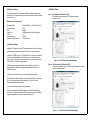
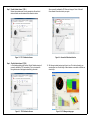
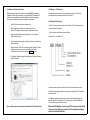
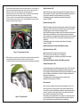
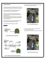
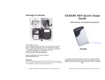
PLATINUM
PRO PLUG-IN
Hyundai Genesis
BK Theta
HALTECH HEAD OFFICE:
PH:
+612 9729 0999
FAX:
+612 9729 0900
EMAIL: [email protected]
HALTECH US OFFICE:
PH:
760 598 1941
FAX:
760 598 1987
EMAIL: [email protected]
See the Haltech Website for your local authorised dealer.
www.haltech.com
Version 6
(HT055045)
QUICK START GUIDE
LIMITED WARRANTY
Lockin Pty Ltd trading as Haltech warrants the Haltech TM Programmable Fuel Injection System to be
free from defects in material or workmanship for a period of 12 months from the date of purchase.
Proof of purchase, in the form of a bill of sale or receipted invoice, which indicates that the product is
within the warranty period, must be presented to obtain warranty service. Lockin Pty Ltd trading as
Haltech suggests that the purchaser retain the dealer’s dated bill of sale as evidence of the date of
retail purchase.
If the HaltechTM Programmable Fuel Injection System is found to be defective as mentioned above, it
will be replaced or repaired if returned prepaid along with proof of purchase. This shall constitute the
sole liability of Lockin Pty Ltd trading as Haltech.
To the extent permitted by law, the foregoing is exclusive and in lieu of all other warranties or
representations, either expressed or implied, including any implied warranty of merchantability or
fitness. In no event shall Lockin Pty Ltd trading as Haltech, be liable for special or consequential
damages.
DISCLAIMER
Haltech will not be held responsible for any damage caused by the incorrect installation or tuning of this
product. It is the installers responsibility to ensure the wiring connections and pinouts match that of the
vehicle the unit is being installed into.
Haltech has taken all care to make sure the connections match the specified vehicles listed, but variations
in wiring and connections on vehicles can occur and therefore this should be checked BEFORE the unit
is installed.
Haltech highly recommends installation and tuning of this product is to be carried out by a professional,
with an understanding on installing and tuning engine management systems.
Misuse of this product can destroy your engine.
WARNING
This ECU is designed and sold for Racing use only. Using this product for street / road use may be
prohibited by law. Please check with your local vehicle authority before using this product.
GENERAL INSTALLATION WARNING
Avoid open sparks, flames or operation of electrical devices near flammable substances.
Always disconnect the battery cables when doing electrical work on your vehicle.
Do not charge the battery with a 24 Volt truck charger or reverse the polarity of the battery
or any charging unit. Do not charge the battery with the engine running as this could
expose the ECU to an unregulated power supply that could destroy the ECU and other
electrical equipment.
All fuel system components and wiring should be mounted away from heat sources,
shielded if necessary and well ventilated. Disconnect the Haltech ECU from the electrical
system whenever doing any arc welding on the vehicle by unplugging the wiring harness
connector from the ECU.
After completing the installation, make sure that there are no fuel leaks, and no wiring
left un-insulated in case a spark or short-circuit occurs and causes a fire. Also make sure
that you follow all proper workshop safety procedures. If you're working underneath
a jacked-up car, always use safety stands!
Notes
PLATINUM Pro Plug-in Hyundai Genesis BK Theta
Quick Start Guide
Congratulations on purchasing a Haltech Engine Management System.
This fully programmable Plug and Play product opens the door to virtually limitless
performance modification and tuning of your vehicle. Programmable systems allow you
to extract all the performance from your engine by delivering precisely the required
amount of fuel and ignition timing that your engine requires for maximum output under
all operating conditions.
This quick start guide will walk you through installation of the Platinum Pro ECU into
a vehicle. This guide is accompanied by the full service manual located on the software
CD provided with the ECU that you or your tuner will need to refer to before completing
your installation and configuration. The Manual can also be downloaded from the
Haltech website www.haltech.com
Supported Vehicles
The Platinum Pro Plug-in Hyundai Genesis BK Theta ECU supports the following:
Hyundai Genesis (USA Only) 2.0L turbo Theta engine
(Key start and Push button start, manual transmission only)
Platinum Pro Plugin Hyundai Genesis BK Theta Kit Includes
•
•
•
•
•
•
•
•
Haltech Platinum Pro Plug-in ECU
Mounting Bracket
Brake Fluid Level Extension Harness
M8 to M6 Grounding Lug Adaptor
Rear Auxiliary Connector and pins
USB Cable
Software CD
Quick Start Guide
Optional Accessories ( Sold Separately )
•
•
Rear Auxiliary Harness ( HT040003 )
3 Bar Map Sensor ( HT010104 )
Loaded Basemap
Your Platinum Pro Plug-in has been programmed with a basemap to suit a
Hyundai Genesis running a Theta 2.0L standard engine with Key Start Option.
Please ensure you load, modify and check the corresponding basemap for your
application and calibrate the Electronic Throttle within ECU Manager software before
attempting to start the vehicle.
ECU Installation
ECU Pinout
To install your new Platinum Pro Plug-in to your Hyundai Genesis, please follow the
procedures below.
1.
Locate your factory ECU. This will be located in the engine bay, near the firewall
on the drivers side. Remove the strut tower brace for easy access.
Looking into ECU connector
Figure 1 – ECU and strut tower bolts location
2.
With the ignition turned off remove the ECU connector from the ECU by lifting the
connector levers up and pulling the connectors out.
With the connectors disconnected, remove the factory ECU from the engine bay by
loosening the 4 x 10mm bolts securing it to the mounting bracket.
Follow ECU Main Wiring Harness to where it enters the junction box mounted to the
strut tower and remove the bolt securing the ground wires to the strut tower.
Figure 2 – Factory harness ground location
Figure 18 – Platinum Pro Plug-in Hyundai Genesis BK Theta
The Haltech CAN Network
3.
Cut the two zip ties that are holding the wiring harness to the plastic junction box and
then undo the bolt holding the junction box to the vehicle.
The Haltech CAN network allows for simple and effective expansion in ECU capability
and functionality without having to go to the trouble of wiring in a whole new computer.
Expansion is made possible by the addition of multiple expansion devices that
communicate to the main ECU via a Control Area Network (CAN).
Installation time and costs are kept to a minimum as all expansion devices are
powered up from the main ECU via the pre-terminated connection cable that comes
with each expansion device.
Simply connect the device directly to the 8 pin CAN connector on the rear of the ECU
or connect using an optional Haltech CAN Hub (order as part # HT059990) if multiple
expansion devices are required).
Each expansion device is pre-programmed with a unique ID code which allows it to
be recognised on the network and work correctly first time every time.
For current available expansion devices please go to our website at
www.haltech.com
Figure 3 – Factory Harness mounting points
4.
Remove the wiring harness from the plastic junction box and set box aside
(you will no longer require this component).
Remove the brake fluid level sensor wire and install the provided extension harness.
Figure 15– Haltech ECU connected to a Racepak Dash
Figure 4 – Brake Fluid Level Sensor Connector
Figure 17 – Haltech ECU connected to 5 Auxiliary CAN based devices
5.
Remove the two firewall mounted nuts that secure the plastic cover over the top of the
wiring harness firewall pass through grommet, once the nuts are removed from the
plastic cover it can be removed to access the pass through grommet.
Removing the plastic cover can be difficult as there is a metal ring that sits inside the
plastic cover and clamps the rubber grommet underneath in place.
The cover is easier to remove with the metal ring remaining seated on the firewall
(ie don’t let the ring come out with the cover, it may be beneficial to remove the brake
booster vacuum hose for easier access).
Digital Pulsed Input ( DPI )
Digital Pulsed Inputs are capable of accepting pulsed input information such as for a
road speed sensor. These inputs measure the time periods between the pulses and
can process this information to provide quantities such as road speed.
One additional input can be connected using the Optional Rear Auxiliary
Harness ( HT040003 )
Digital Pulsed Outputs ( DPO )
Digital Pulsed Outputs are capable of producing pulsed waveforms with varying duty
and frequency. DPO's can be used to control various devices such as thermo-fans,
shift lights, bypass air control valves, boost control solenoids etc.
When a Digital Pulsed output is activated by the ECU the output will switch to ground.
Solenoid valves and shift lights etc can be run directly from the output, however
high current devices such as thermo-fans and additional fuel pumps must be activated
through a relay. This way the DPO is only switching a relay and not a high current
draw device.
Two additional outputs can be connected using the Optional Rear Auxiliary
Harness ( HT040003 )
Digital Pulsed Outputs are limited to 800mA Max current draw.
Digital Switched Outputs ( DSO )
Figure 5 – Factory Grommet Location
6.
With the plastic cover removed you should be able to access the rubber grommet that
the wiring harness passes through into the cabin, remove the metal ring,
cut the grommet and route the wiring harness through into the passenger compartment.
Digital Switched Outputs are capable of switching to ground
DSO's can be used to control relays in an on / off state only.
Two additional outputs can be connected using the Optional Rear Auxiliary
Harness ( HT040003 )
Digital Switched Outputs are limited to 800mA Max current draw.
Analogue Voltage Inputs ( AVI )
Analogue Voltage Inputs accept variable voltage inputs from 0V to 5V. These inputs
can also accept switch inputs that change between two different voltage levels.
The On Voltage and Off Voltage define what the thresholds are between the On and Off
states. The Voltage can be viewed as a channel in the software to determine the
thresholds for a switched input.
Two additional sensors or switched inputs can be connected using the
Optional Rear Auxiliary Harness ( HT040003 )
Wire connections
Figure 6 – Factory Grommet
When using crimp connectors ensure that the correct crimping tool is used – if in
doubt do a pull test on a crimp connector, the wire should break before the wire
pulls out of the crimp. Terminal soldering can weaken a connection and should only
be used as a last resort. If solder joints are used, ensure joints are well isolated
from movement as solder joints are prone to fracture.
When splicing 2 wires it is preferable to use a crimp splice – again if using a solder
joint, ensure joint is limited in its range of possible movement as solder joints are
prone to fracture. Always use heat-shrink sleeving to insulate wires.
7.
Rear Auxiliary Connector
The Platinum Pro Plugin Series allows further expansion of your ECU by the
Rear Auxiliary Connector.
•
•
•
•
•
•
•
The Rear Auxiliary connector allows you access to:
1 Additional Digital Pulsed Input ( DPI )
2 Additional Digital Pulsed Outputs ( DPO )
2 Additional Digital Switched Outputs ( DSO )
4 Additional Analogue Voltage Inputs ( AVI )
2 Additional +13.8V Sensor Power Outputs ( limited to 500mA Per output pin )
2 Additional +5V Sensor Power Output ( limited to 50mA Per output pin )
Additional Sensor Power and Signal Grounds
•
•
•
These extra Inputs / Outputs can be used to:
Fit additional sensors. (eg MAP,Temperature and Flex Fuel )
Control additional devices via relays
Control additional solenoids directly (eg Aftermarket Boost Control solenoid)
Figure 7 – Factory Wiring Harness Re- Routed into Cabin
The Rear Auxiliary harness is available as an optional extra. ( HT040003 )
8.
8
7
6
5
4
3
2
With the plastic cover removed you should be able to access the rubber grommet that
the wiring harness passes through into the cabin, remove the metal ring, cut the
grommet and route the wiring harness through into the passenger compartment.
Mount ECU in appropriate location inside the passenger compartment using the
supplied mounting bracket. Reinstall the ground wire that was previously mounted to
the strut tower to a chassis ground lug using the M8 to M6 adaptor provided.
1
16 15 14 13 12 11 10 9
Pin #
1
2
3
4
5
6
7
8
9
10
11
12
13
14
15
16
Looking
into Back Of Connector
Wire
Colour
Connection
O
+5V (50mA Max)
Y
AVI1 (MAP)
O/B
AVI2
B/W
SIGNAL GROUND
V/B
DPO1
V/BR
DPO2
GY<SHD>
DPI1
R
+13.8V (500mA Max)
O
+5V (50mA Max)
GY
AVI 3
GY/B
AVI 4
B/W
SIGNAL GROUND
V/R
DSO1
V/O
DSO2
R
+13.8V (500mA Max)
<SHD> Denotes shielded cable
Figure 16 - Rear Auxiliary Harness Connector and Pin-out
Figure 8 – Haltech ECU Mounted Under Dashboard of the Vehicle
9.
Calibration of the Electronic Throttle
ECU Manager / ECU Manuals
Before trying to start the vehicle the Electronic throttle MUST be calibrated.
Calibration of the throttle is achieved by using the Haltech ECU Manager ETC
Calibration wizard located in the Advanced Tab within the Main setup page.
The process to Calibrate the Electronic Throttle is outlined below.
Detailed manuals can be found in the software by pressing your F1 key or by
selecting the Help tab located at the top left of the screen
ECU Manager File Extensions
•
Install ECU into vehicle as described previously
•
With the ignition switch turned on, connect to the ECU via
Haltech ECU Manager Software using the USB cable provided
•
Navigate to the Main Setup page by pressing F4 or by using the
Setup / Main Setup Tabs
•
Go to the Advanced setup page via selecting the icon on the left of the
main setup page
•
Select Electronic Throttle Tab to display the Haltech Electronic Throttle
Calibration wizard, we are now ready to calibrate the throttle.
To begin the calibration process select the Start >> button
•
The Haltech Calibration wizard will now guide you though the Electronic
Throttle Calibration.
When ECU manager saves the map from the Haltech ECU, it saves the map with
a Haltech specific file extension.
The File extension can be broken down as follows:
Example File : xxxx.hbktheta-111
Later map versions cannot be loaded into ECU's with earlier firmware versions.
ECU Manager will upgrade earlier map versions when loading into ECU's with later
firmware versions.
ECU Manager upgrades maps between versions where equivalent settings are
available. However, new settings not in the original map, will be substituted with
values from the new version's default map.
Figure 9- Main Setup Page showing Advanced Menu ETC Calibration Wizard
Whenever ECU Manager converts your ECU map, you should always
check your map settings to ensure that all the appropriate settings
have been converted correctly.
ECU Manager Software
Calibration Steps
ECU Manager software is used for setup, calibration and diagnostics and can
be found on the CD supplied with this unit or downloaded from the Haltech website
www.haltech.com
Step 1: 0% Accelerator Pedal Position ( APP )
Ensure that the accelerator pedal is NOT depressed and click
the calibrate button
Minimum System Requirements
Operating System:
Processor Speed:
RAM:
Video Card:
USB:
Hard Drive Space:
Minimum Screen Resolution:
Windows 2000 SP4 / XP / Vista / Windows 7
1GHz
256 MB
128MB graphics card with 3D acceleration
1.1
250Mb
1024 x 768 pixels
Installing ECU Manager
Installing ECU Manager onto your PC is performed similar to any other Windows
software package. Installation is outlined below to ensure correct installation:
1.Insert the CD-ROM into your PC’s CD-ROM drive. The CD should automatically
launch into the Haltech Browser. If the CD does not run automatically double
click on the “My Computer” icon on the desktop, double click on the Haltech icon
(CD- ROM drive) to start the browser software.
2.The Browser will display the disclaimer and you will need to agree to the
terms stated before allowing to progress. Read the Disclaimer and click on
AGREE if you agree.
Figure 10 – 0% APP Successful calibration display
Step 2: 100% Accelerator Pedal Position ( APP )
Fully press the accelerator pedal. Continue to hold the pedal in this position
and click the calibrate button
3.Now you will be able to access all the information contained on the CD
4.To download the Platinum Software, click on the Platinum Series ECU Manager
Link. You will be prompted to install the software. Click “Install” to install
ECU Manager and the Data Log viewer.
5. Follow the software prompts and install the software.
With your programming cable (USB) attached to your ECU and the other end
connected to your laptop, power up the ECU by turning your key to IGN. Start the
programming software on your PC and go online with the ECU.
Figure 11 – 100% APP Successful Calibration display
Step 3: Throttle Position Sensor 1 (TPS 1)
Release the accelerator pedal to a non-pressed state. Ensure that all
electronic throttles are connected and click calibrate to continue
Figure 12 – TPS 1 Calibration Success
Step 4: Throttle Position Sensor 2 (TPS 2)
In Twin throttle applications the Electronic Throttle Calibration wizard will
proceed to calibrate the TPS 2 automatically. This is not required with
this application and will be skipped automatically by the wizard
Figure 13 – TPS 2 Calibration Success
When successfully calibrated the ETC Status will change to “Online / Calibrated”
Once calibrated its now time to start your engine.
Figure 14 – Successful Calibration Indication
10. With the engine started and running its time to tune. This is best achieved by your
nearest engine tuner. See the listing of Haltech dealers on our website to find the one
closest to you.
Figure 15 – ECU Manager tuning page
ECU Manager Software
Calibration Steps
ECU Manager software is used for setup, calibration and diagnostics and can
be found on the CD supplied with this unit or downloaded from the Haltech website
www.haltech.com
Step 1: 0% Accelerator Pedal Position ( APP )
Ensure that the accelerator pedal is NOT depressed and click
the calibrate button
Minimum System Requirements
Operating System:
Processor Speed:
RAM:
Video Card:
USB:
Hard Drive Space:
Minimum Screen Resolution:
Windows 2000 SP4 / XP / Vista / Windows 7
1GHz
256 MB
128MB graphics card with 3D acceleration
1.1
250Mb
1024 x 768 pixels
Installing ECU Manager
Installing ECU Manager onto your PC is performed similar to any other Windows
software package. Installation is outlined below to ensure correct installation:
1.Insert the CD-ROM into your PC’s CD-ROM drive. The CD should automatically
launch into the Haltech Browser. If the CD does not run automatically double
click on the “My Computer” icon on the desktop, double click on the Haltech icon
(CD- ROM drive) to start the browser software.
2.The Browser will display the disclaimer and you will need to agree to the
terms stated before allowing to progress. Read the Disclaimer and click on
AGREE if you agree.
Figure 10 – 0% APP Successful calibration display
Step 2: 100% Accelerator Pedal Position ( APP )
Fully press the accelerator pedal. Continue to hold the pedal in this position
and click the calibrate button
3.Now you will be able to access all the information contained on the CD
4.To download the Platinum Software, click on the Platinum Series ECU Manager
Link. You will be prompted to install the software. Click “Install” to install
ECU Manager and the Data Log viewer.
5. Follow the software prompts and install the software.
With your programming cable (USB) attached to your ECU and the other end
connected to your laptop, power up the ECU by turning your key to IGN. Start the
programming software on your PC and go online with the ECU.
Figure 11 – 100% APP Successful Calibration display
9.
Calibration of the Electronic Throttle
ECU Manager / ECU Manuals
Before trying to start the vehicle the Electronic throttle MUST be calibrated.
Calibration of the throttle is achieved by using the Haltech ECU Manager ETC
Calibration wizard located in the Advanced Tab within the Main setup page.
The process to Calibrate the Electronic Throttle is outlined below.
Detailed manuals can be found in the software by pressing your F1 key or by
selecting the Help tab located at the top left of the screen
ECU Manager File Extensions
•
Install ECU into vehicle as described previously
•
With the ignition switch turned on, connect to the ECU via
Haltech ECU Manager Software using the USB cable provided
•
Navigate to the Main Setup page by pressing F4 or by using the
Setup / Main Setup Tabs
•
Go to the Advanced setup page via selecting the icon on the left of the
main setup page
•
Select Electronic Throttle Tab to display the Haltech Electronic Throttle
Calibration wizard, we are now ready to calibrate the throttle.
To begin the calibration process select the Start >> button
•
The Haltech Calibration wizard will now guide you though the Electronic
Throttle Calibration.
When ECU manager saves the map from the Haltech ECU, it saves the map with
a Haltech specific file extension.
The File extension can be broken down as follows:
Example File : xxxx.hbktheta-111
Later map versions cannot be loaded into ECU's with earlier firmware versions.
ECU Manager will upgrade earlier map versions when loading into ECU's with later
firmware versions.
ECU Manager upgrades maps between versions where equivalent settings are
available. However, new settings not in the original map, will be substituted with
values from the new version's default map.
Figure 9- Main Setup Page showing Advanced Menu ETC Calibration Wizard
Whenever ECU Manager converts your ECU map, you should always
check your map settings to ensure that all the appropriate settings
have been converted correctly.
7.
Rear Auxiliary Connector
The Platinum Pro Plugin Series allows further expansion of your ECU by the
Rear Auxiliary Connector.
•
•
•
•
•
•
•
The Rear Auxiliary connector allows you access to:
1 Additional Digital Pulsed Input ( DPI )
2 Additional Digital Pulsed Outputs ( DPO )
2 Additional Digital Switched Outputs ( DSO )
4 Additional Analogue Voltage Inputs ( AVI )
2 Additional +13.8V Sensor Power Outputs ( limited to 500mA Per output pin )
2 Additional +5V Sensor Power Output ( limited to 50mA Per output pin )
Additional Sensor Power and Signal Grounds
•
•
•
These extra Inputs / Outputs can be used to:
Fit additional sensors. (eg MAP,Temperature and Flex Fuel )
Control additional devices via relays
Control additional solenoids directly (eg Aftermarket Boost Control solenoid)
Figure 7 – Factory Wiring Harness Re- Routed into Cabin
The Rear Auxiliary harness is available as an optional extra. ( HT040003 )
8.
8
7
6
5
4
3
2
With the plastic cover removed you should be able to access the rubber grommet that
the wiring harness passes through into the cabin, remove the metal ring, cut the
grommet and route the wiring harness through into the passenger compartment.
Mount ECU in appropriate location inside the passenger compartment using the
supplied mounting bracket. Reinstall the ground wire that was previously mounted to
the strut tower to a chassis ground lug using the 8mm to 6mm adaptor provided.
1
16 15 14 13 12 11 10 9
Pin #
1
2
3
4
5
6
7
8
9
10
11
12
13
14
15
16
Looking
into Back Of Connector
Wire
Colour
Connection
O
+5V (50mA Max)
Y
AVI1 (MAP)
O/B
AVI2
B/W
SIGNAL GROUND
V/B
DPO1
V/BR
DPO2
GY<SHD>
DPI1
R
+13.8V (500mA Max)
O
+5V (50mA Max)
GY
AVI 3
GY/B
AVI 4
B/W
SIGNAL GROUND
V/R
DSO1
V/O
DSO2
R
+13.8V (500mA Max)
<SHD> Denotes shielded cable
Figure 16 - Rear Auxiliary Harness Connector and Pin-out
Figure 8 – Haltech ECU Mounted Under Dashboard of the Vehicle
5.
Remove the two firewall mounted nuts that secure the plastic cover over the top of the
wiring harness firewall pass through grommet, once the nuts are removed from the
plastic cover it can be removed to access the pass through grommet.
Removing the plastic cover can be difficult as there is a metal ring that sits inside the
plastic cover and clamps the rubber grommet underneath in place.
The cover is easier to remove with the metal ring remaining seated on the firewall
(ie don’t let the ring come out with the cover, it may be beneficial to remove the brake
booster vacuum hose for easier access).
Digital Pulsed Input ( DPI )
Digital Pulsed Inputs are capable of accepting pulsed input information such as for a
road speed sensor. These inputs measure the time periods between the pulses and
can process this information to provide quantities such as road speed.
One additional input can be connected using the Optional Rear Auxiliary
Harness ( HT040003 )
Digital Pulsed Outputs ( DPO )
Digital Pulsed Outputs are capable of producing pulsed waveforms with varying duty
and frequency. DPO's can be used to control various devices such as thermo-fans,
shift lights, bypass air control valves, boost control solenoids etc.
When a Digital Pulsed output is activated by the ECU the output will switch to ground.
Solenoid valves and shift lights etc can be run directly from the output, however
high current devices such as thermo-fans and additional fuel pumps must be activated
through a relay. This way the DPO is only switching a relay and not a high current
draw device.
Two additional outputs can be connected using the Optional Rear Auxiliary
Harness ( HT040003 )
Digital Pulsed Outputs are limited to 800mA Max current draw.
Digital Switched Outputs ( DSO )
Figure 5 – Factory Grommet Location
6.
With the plastic cover removed you should be able to access the rubber grommet that
the wiring harness passes through into the cabin, remove the metal ring,
cut the grommet and route the wiring harness through into the passenger compartment.
Digital Switched Outputs are capable of switching to ground
DSO's can be used to control relays in an on / off state only.
Two additional outputs can be connected using the Optional Rear Auxiliary
Harness ( HT040003 )
Digital Switched Outputs are limited to 800mA Max current draw.
Analogue Voltage Inputs ( AVI )
Analogue Voltage Inputs accept variable voltage inputs from 0V to 5V. These inputs
can also accept switch inputs that change between two different voltage levels.
The On Voltage and Off Voltage define what the thresholds are between the On and Off
states. The Voltage can be viewed as a channel in the software to determine the
thresholds for a switched input.
Two additional sensors or switched inputs can be connected using the
Optional Rear Auxiliary Harness ( HT040003 )
Wire connections
Figure 6 – Factory Grommet
When using crimp connectors ensure that the correct crimping tool is used – if in
doubt do a pull test on a crimp connector, the wire should break before the wire
pulls out of the crimp. Terminal soldering can weaken a connection and should only
be used as a last resort. If solder joints are used, ensure joints are well isolated
from movement as solder joints are prone to fracture.
When splicing 2 wires it is preferable to use a crimp splice – again if using a solder
joint, ensure joint is limited in its range of possible movement as solder joints are
prone to fracture. Always use heat-shrink sleeving to insulate wires.
The Haltech CAN Network
3.
Cut the two zip ties that are holding the wiring harness to the plastic junction box and
then undo the bolt holding the junction box to the vehicle.
The Haltech CAN network allows for simple and effective expansion in ECU capability
and functionality without having to go to the trouble of wiring in a whole new computer.
Expansion is made possible by the addition of multiple expansion devices that
communicate to the main ECU via a Control Area Network (CAN).
Installation time and costs are kept to a minimum as all expansion devices are
powered up from the main ECU via the pre-terminated connection cable that comes
with each expansion device.
Simply connect the device directly to the 8 pin CAN connector on the rear of the ECU
or connect using an optional Haltech CAN Hub (order as part # HT059990) if multiple
expansion devices are required).
Each expansion device is pre-programmed with a unique ID code which allows it to
be recognised on the network and work correctly first time every time.
For current available expansion devices please go to our website at
www.haltech.com
Figure 3 – Factory Harness mounting points
4.
Remove the wiring harness from the plastic junction box and set box aside
(you will no longer require this component).
Remove the brake fluid level sensor wire and install the provided extension harness.
Figure 15– Haltech ECU connected to a Racepak Dash
Figure 4 – Brake Fluid Level Sensor Connector
Figure 17 – Haltech ECU connected to 5 Auxiliary CAN based devices
ECU Installation
ECU Pinout
To install your new Platinum Pro Plug-in to your Hyundai Genesis, please follow the
procedures below.
1.
Locate your factory ECU. This will be located in the engine bay, near the firewall
on the drivers side. Remove the strut tower brace for easy access.
Looking into ECU connector
Figure 1 – ECU and strut tower bolts location
2.
With the ignition turned off remove the ECU connector from the ECU by lifting the
connector levers up and pulling the connectors out.
With the connectors disconnected, remove the factory ECU from the engine bay by
loosening the 4 x 10mm bolts securing it to the mounting bracket.
Follow ECU Main Wiring Harness to where it enters the junction box mounted to the
strut tower and remove the bolt securing the ground wires to the strut tower.
Figure 2 – Factory harness ground location
Figure 18 – Platinum Pro Plug-in Hyundai Genesis BK Theta
Notes
PLATINUM Pro Plug-in Hyundai Genesis BK Theta
Quick Start Guide
Congratulations on purchasing a Haltech Engine Management System.
This fully programmable Plug and Play product opens the door to virtually limitless
performance modification and tuning of your vehicle. Programmable systems allow you
to extract all the performance from your engine by delivering precisely the required
amount of fuel and ignition timing that your engine requires for maximum output under
all operating conditions.
This quick start guide will walk you through installation of the Platinum Pro ECU into
a vehicle. This guide is accompanied by the full service manual located on the software
CD provided with the ECU that you or your tuner will need to refer to before completing
your installation and configuration. The Manual can also be downloaded from the
Haltech website www.haltech.com
Supported Vehicles
The Platinum Pro Plug-in Hyundai Genesis BK Theta ECU supports the following:
Hyundai Genesis (USA Only) 2.0L turbo Theta engine
(Key start and Push button start, manual transmission only)
Platinum Pro Plugin Hyundai Genesis BK Theta Kit Includes
•
•
•
•
•
•
•
•
Haltech Platinum Pro Plug-in ECU
Mounting Bracket
Brake Fluid Level Extension Harness
M8 to M6 Grounding Lug Adaptor
Rear Auxiliary Connector and pins
USB Cable
Software CD
Quick Start Guide
Optional Accessories ( Sold Separately )
•
•
Rear Auxiliary Harness ( HT040003 )
3 Bar Map Sensor ( HT010104 )
Loaded Basemap
Your Platinum Pro Plug-in has been programmed with a basemap to suit a
Hyundai Genesis running a Theta 2.0L standard engine with Key Start Option.
Please ensure you load, modify and check the corresponding basemap for your
application and calibrate the Electronic Throttle within ECU Manager software before
attempting to start the vehicle.
LIMITED WARRANTY
Lockin Pty Ltd trading as Haltech warrants the Haltech TM Programmable Fuel Injection System to be
free from defects in material or workmanship for a period of 12 months from the date of purchase.
Proof of purchase, in the form of a bill of sale or receipted invoice, which indicates that the product is
within the warranty period, must be presented to obtain warranty service. Lockin Pty Ltd trading as
Haltech suggests that the purchaser retain the dealer’s dated bill of sale as evidence of the date of
retail purchase.
If the HaltechTM Programmable Fuel Injection System is found to be defective as mentioned above, it
will be replaced or repaired if returned prepaid along with proof of purchase. This shall constitute the
sole liability of Lockin Pty Ltd trading as Haltech.
To the extent permitted by law, the foregoing is exclusive and in lieu of all other warranties or
representations, either expressed or implied, including any implied warranty of merchantability or
fitness. In no event shall Lockin Pty Ltd trading as Haltech, be liable for special or consequential
damages.
DISCLAIMER
Haltech will not be held responsible for any damage caused by the incorrect installation or tuning of this
product. It is the installers responsibility to ensure the wiring connections and pinouts match that of the
vehicle the unit is being installed into.
Haltech has taken all care to make sure the connections match the specified vehicles listed, but variations
in wiring and connections on vehicles can occur and therefore this should be checked BEFORE the unit
is installed.
Haltech highly recommends installation and tuning of this product is to be carried out by a professional,
with an understanding on installing and tuning engine management systems.
Misuse of this product can destroy your engine.
WARNING
This ECU is designed and sold for Racing use only. Using this product for street / road use may be
prohibited by law. Please check with your local vehicle authority before using this product.
GENERAL INSTALLATION WARNING
Avoid open sparks, flames or operation of electrical devices near flammable substances.
Always disconnect the battery cables when doing electrical work on your vehicle.
Do not charge the battery with a 24 Volt truck charger or reverse the polarity of the battery
or any charging unit. Do not charge the battery with the engine running as this could
expose the ECU to an unregulated power supply that could destroy the ECU and other
electrical equipment.
All fuel system components and wiring should be mounted away from heat sources,
shielded if necessary and well ventilated. Disconnect the Haltech ECU from the electrical
system whenever doing any arc welding on the vehicle by unplugging the wiring harness
connector from the ECU.
After completing the installation, make sure that there are no fuel leaks, and no wiring
left un-insulated in case a spark or short-circuit occurs and causes a fire. Also make sure
that you follow all proper workshop safety procedures. If you're working underneath
a jacked-up car, always use safety stands!
PLATINUM
PRO PLUG-IN
Hyundai Genesis
BK Theta
HALTECH HEAD OFFICE:
PH:
+612 9729 0999
FAX:
+612 9729 0900
EMAIL: [email protected]
HALTECH US OFFICE:
PH:
760 598 1941
FAX:
760 598 1987
EMAIL: [email protected]
See the Haltech Website for your local authorised dealer.
www.haltech.com
Version 6
(HT055045)
QUICK START GUIDE