1
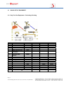
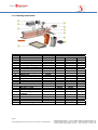
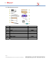
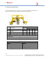
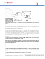
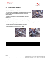
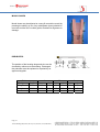
THERMIT WELDING (GB) LTD PROCESS MANUALS SECTION THREE EQUIPMENT Page | 1 Thermit Welding (GB) Limited, 87 Ferry Lane, Rainham, Essex, RM13 9YH, . SECTION 3 – EQUIPMENT Section 3 provides a list of all the recommended items of equipment to be use with the SkV-E process, with guidelines for operation and regular maintenance. SECTION PAGE 3.1 3.1.1 3.1.2 3.1.3 3.1.4 3.1.5 3.1.6 3.1.7 BASIC SET OF EQUIPMENT Oxy fuel gas equipment Crucible and fittings Rail Preparation Welding Attachments Miscellaneous Tools Weld Finishing Electric Rail Profile Grinder 3 3 4 5 6 7 8 9 3.2 3.2.1 3.2.2 OPTIONAL TOOLS Fume extraction device for Thermit Rail Welding Enviro-cap for SUC 10 11 14 3.3 3.3.1 POST WELD HEAT TREATMENT Thermit Insulating muffle 16 16 WELD INSPECTION 17 MAINTENANCE OF EQUIPMENT 18 3.4 Page | 2 Thermit Welding (GB) Limited, 87 Ferry Lane, Rainham, Essex, RM13 9YH, . 3.1 BASIC SET OF EQUIPMENT 3.1.1 Oxy Fuel Gas Equipment - Preheating & Cutting ITEM DESCRIPTION COMMON 1 2 3 4 5 6 7 8 9 10 11 Regulator Flash Back arrestor Hose including fittings Pressure check Gauge Standard guide roller Wide gap guide roller Mark II guide attachment Cylinder spanner Regulator multispanner Mixer stem Cutting torch Pre-heating burner TW PART NUMBER OXYGEN PROPANE 107900 108100 107500 107300 106700 106900 109100 109150 ACETYLENE 107700 107300 107100 109160 111500 111501 110701 109300 108300 PROCESS ALL ALL SKV-E SKV SRZ SmW SoWoS NOTES For spare parts, maintenance please call Page | 3 Thermit Welding (GB) Limited, 87 Ferry Lane, Rainham, Essex, RM13 9YH, . 102900 105500 100701 100700 100400 100500 100500 102900 105600 100101 100100 100100 100100 100100 3.1.2 Crucibles and Fittings ITEM 1 2 3 4 5 6 7 8 9 10 DESCRIPTION TW PART NUMBER Crucible cap – standard Crucible extension ring Crucible clamping ring Crucible lining Crucible tripod stand Crucible drying clamp Thimble applicator Thimble drift Paste Applicator SUC Locating ring 112300 113500 114100 301802 114300 112000 137100 137300 301801 114400 Page | 4 Thermit Welding (GB) Limited, 87 Ferry Lane, Rainham, Essex, RM13 9YH, . 3.1.3. Rail Preparation ITEM DESCRIPTION TW PART NUMBER COMMON 1 2 3 4 5 6 1 Metre Straight edge Rail thermometer TW Rail wear gauge 300mm Steel rule Rail wedge - large Rail wedge - small 139200 137700 144500 145030 137810 137800 7 Distance gauge PROCESS SkV-E 8 Cutting guide Vignole rail Standard 60E1 BS80A 110900 111300 110900 9 Mk II Cutting guide Vignole rail Standard 60E1 110700 110780 OXY/PROPANE NOTES For other applications please call Page | 5 Thermit Welding (GB) Limited, 87 Ferry Lane, Rainham, Essex, RM13 9YH, . OXY/ACETYLENE 3.1.4. Welding Attachments ITEM DESCRIPTION COMMON TW PART NUMBER SPECIAL BS80A 1 2 3 4 5 6 7 8 9 10 Rail cover - small Rail cover - large Mould alignment gauge Sand tray FPH Preheater holder Standard Preheater holder Universal Mounting Mould cover Mould shoes Slag Bowl MOULD SHOES SkV-SUC Straight SkV-SUC 7-9 step SkV-SUC 3 piece SkV – Composite 110A/80A 129500 129700 144700 136310 118520 118500 116300 127300 See Below 131900 123000 NOTES For other applications please call Page | 6 Thermit Welding (GB) Limited, 87 Ferry Lane, Rainham, Essex, RM13 9YH, . 116900 95R BH 54E1 56E1 60E1 126120 126123 126140 126143 126160 3.1.5. Miscellaneous hand tools ITEM 1 2 3 4 5 6 7 8 9 10 11 12 13 DESCRIPTION Ramming tool Luting tool – standard Slag bowl lifting tool Tongs 3lb Hammer Chipping Hammer File Wire Brush Welders Mittens Flip Front Goggles Spark Lighter Digital Stop Watch Nozzle cleaners Page | 7 Thermit Welding (GB) Limited, 87 Ferry Lane, Rainham, Essex, RM13 9YH, . TW PART NUMBER 136300 135900 135700 136900 134500 134100 139900 139700 137500 137400 110300 141900 110100 3.1.6 Weld Finishing Items required for weld finishing and cleaning include: Item Example ( for information only) Approved Hydraulic Weld Trimmer Grinding equipment and stones Needle Gun Wire brush Chipping hammer Straightedge TW UL Geismar MP 12 110v Bosch Hammer GPH 4DSC TW Part no 139700 TW Part no 134100 TW part no 139200 Thermit Weld Trimmer The Thermit weld trimmer is equipped with two replaceable blades. Clamps are fitted to lock the unit to the rail to such that the weld is trimmed close to the rail profile. The basic machine is equipped with a manual pump with removable handle which operates from side to side. For Network Rail applications, the trimmer can be supplied with a longitudinal pump action. Blades are available to fit a range of rail profiles. DESCRIPTION COMMON TW/UL Trimmer, standard lever action Vignole rails incl. 1 set blades TW/UL Trimmer, longitudinal pump action Vignole rails – incl. 1 set blades TW PART NUMBER APPLICATION 54E1 56E1 60E1 137901 BS80A 137902 137951 REPLACEMENT ITEMS Blades (1 set) Pump unit complete 3 way valve TW/UL Valve Handle Hydraulic cylinder 138901 138902 138010 138330 138541 138400 FOR OTHER SPARES PLEASE CALL TECHNICAL DATA (TW/UL) Maximum trimming stroke Maximum trimming force Maximum working pressure Weight (Standard Lever) Oil type Capacity Page | 8 Thermit Welding (GB) Limited, 87 Ferry Lane, Rainham, Essex, RM13 9YH, . 155mm 200kN 500 Bar 52kg including handle, oil and blades Tellus 32 or equivalent (ISO VG 22) 0.6L 3.1.7 Electric Rail Profile Grinder The Thermit Grinding Frame is designed for use with a standard Bosch 8” (200mm) disc grinder and allows the grinder to be used to profile finish a welded joint. TW Part No Item Description 1 Comm on 141700 Grinding Frame – Type SVW Bosch Angle Grinder – Model 2 141703 23/180S 3 Cupped Wheel Guard 141704 4 Spanner 141705 5 Cupped Grinding Wheels 305200 NOTES The Bosch Angle Grinder may be purchased locally if preferred.-type 180s or equivalent For replacement items, and rail guides/rollers –please call TECHNICAL DATA Length Height Width Distance between rollers Gross Weight Electrical supply 840 mm 470 mm 800 mm 860 mm 30kg including grinder 110V (50Hz) Page | 9 Thermit Welding (GB) Limited, 87 Ferry Lane, Rainham, Essex, RM13 9YH, . 3.2 OPTIONAL ITEMS Item Rail Alignment Tools Weather Protection Fume extraction for Reuseable Crucible Enviro-cap for SUC Weld Identification stamps Example ( for information only) SmartWeld Rail Setter TW part No 170100 Lawton Tools Umbrella & support Sheerspeed welding tent TW part no. 150000 TW part no. 150010 Page | 10 Thermit Welding (GB) Limited, 87 Ferry Lane, Rainham, Essex, RM13 9YH, . 3.2.1 Fume Extraction Device for Thermit® Rail Welding The Thermit Welding Fume Extractor is a wet scrubbing device available for use with THERMIT® rail welding processes to collect fume emission from the THERMIT® reaction when welding in confined areas e.g. underground or in tunnels. Volatile products are emitted from the THERMIT® reaction for approximately 20 seconds. These consist of oxides of iron and aluminium - nuisance fume - together with toxic manganese oxide. The emission can easily be collected using the device, thereby minimising any risk to personnel operating in an enclosed environment, where the concentration of fume in the surrounding atmosphere may build up and exceed permitted threshold values. Operating Principle Dust and gases generated by the THERMIT® reaction are evacuated via a modified crucible cap and metallic hose into a filter unit. The fumes are scrubbed through a water bath and fibre glass filter so that dust particles are retained. The cleaned gases are then exhausted from the unit to atmosphere. The suction in the vessel is created by a venturi injector in the exhaust tube powered by compressed air or Nitrogen cylinder. Page | 11 Thermit Welding (GB) Limited, 87 Ferry Lane, Rainham, Essex, RM13 9YH, . Description The THERMIT® weld is made in the normal way using standard equipment. The suction hood (1) replaces the normal crucible cap. This hood is provided with a covered aperture to allow the THERMIT® charge to be ignited in the usual way. The suction hood is fabricated with an outlet pipe for connection to the filter unit via a flexible steel hose (2). The scrubber unit (3) consists of a water tank containing 9 to 10 litres of water (filled via 3.2) A level plug is fitted to the side of the tank (3.1). On top of the scrubber is mounted a filter (3.3) containing fibre glass discs and to this is attached the venturi system with injector nozzle and inlet valve. The exhaust end of the venturi is fitted with a cartridge type filter (3.4). The airline (4) is connected to the inlet end of the venturi pipe with a quick release coupling. The unit can be operated with on line compressed air or a compressed air or nitrogen cylinder via a regulator (5). Operation The air / nitrogen supply should be regulated at 2.0 bar (29 psi) before commencing welding operations and the unit coupled up to the crucible. Before ignition of the THERMIT® charge the air / nitrogen supply must be turned on. As soon as the steel has been discharged from the crucible into the moulds and the pour is completed, the supply may be turned off. Maintenance of Unit The water in the scrubber must be changed after not more than 6 welds, and the tank washed out. The fibre glass filters must be inspected at frequent intervals. If they are clogged they should be shaken or renewed. Replacement filters may be purchased from Thermit Welding (GB) Limited. The cartridge filter should be replaced when clogged (- every 50 welds). Page | 12 Thermit Welding (GB) Limited, 87 Ferry Lane, Rainham, Essex, RM13 9YH, . If inadequate suction is available with the unit operating at 2.0 bar (29 psi) the cause is almost certainly a clogged filter. Dos and Do Not’s: DO treat the flexible hose carefully or the ends will become damaged. DO change the water in the tank regularly for efficient cleaning of the gases. DO inspect the glass fibre filter regularly to check that it is not clogged. DO NOT overfill the tank or entrained water will be carried over and waterlog the fibre glass filter. DO NOT use air pressures above 2.0 bar (29 psi) or water can be blown out of the exhaust. Page | 13 Thermit Welding (GB) Limited, 87 Ferry Lane, Rainham, Essex, RM13 9YH, . 3.2.2 Enviro-Cap for use with the Single Use Crucible The Enviro-Cap is designed to be used with our Single Use Crucible when welding in confined spaces. Volatile products are emitted from the THERMIT® reaction for approximately 20 seconds. These consist of oxides of iron and aluminium - nuisance fume - together with toxic manganese oxide. The emission can easily be collected using the device, thereby minimising any risk to personnel operating in an enclosed environment, where the concentration of fume in the surrounding atmosphere may build up and exceed permitted threshold values. Operating Principle Dust and gases generated by the THERMIT® reaction are collected by the Enviro-Cap which is fitted to our standard single use crucibles. The fume cap contains filters which remove fumes and dust particles. ITEM DESCRIPTION TW PART NUMBER Enviro-cap - Complete 150010 REPLACEMENT PARTS Replacement filters Sealant 301900 301801 Operation The THERMIT® weld is made in the normal way using standard equipment. The recess within the crucible lid is filled with a single bead of crucible sealant paste prior to use. To prevent the igniter being pushed too far into the Thermit portion the end of the igniter should be bent over, shortening the overall length by approximately 150mm. Once the Thermit ® has started the Enviro-Cap is placed firmly into the recess in the crucible cap. The Enviro-Cap will not affect the reaction of the portion or the tap time. The Enviro-Cap should remain in place for one minute following completion of the pour and then be removed independently of the empty SUC. The Enviro-Cap contains a series of baffle plates and two replaceable filters Trials have shown that the filters are effective for up to at least 10 welds, depending on the size of the portion being used. It is recommended that the filters are reversed after six welds. Page | 14 Thermit Welding (GB) Limited, 87 Ferry Lane, Rainham, Essex, RM13 9YH, . To replace the filters first ensure that the Enviro-Cap is cold, remove the two wing nuts (or clips) and remove the lid. The two replaceable filters are located in the top of the Enviro-Cap. Take out the used filters and replace with new, ensuring that the new filters are pushed down to completely fill the void in the top of the Enviro-Cap, there should be no spaces around the edge of the filters. The lid is then replaced and secured with the two wing nuts (or clips). Page | 15 Thermit Welding (GB) Limited, 87 Ferry Lane, Rainham, Essex, RM13 9YH, . 3.3 POST WELD HEAT TREATMENT 3.3.1 Thermit Weld Insulating Muffle The Thermit Weld Insulated Muffle is designed to control the cooling of welds in rails sensitive to rapid cooling as may occur under adverse weather. The muffle is required for use when welding 260Mn and 320Cr grades of rail. On completion of weld trimming, and not later than the time specified in Section 2, the excess head riser and mould is removed and placed in a safe position. The base of the muffle box is placed under the rail about the weld and clamped to the rail foot using the locating pegs. The upper half of the box is positioned on top of the base. The box remains in place for a minimum of 1 hour. RAIL PROFILE BS113A 60E1 INSULATING MUFFLE PART NUMBER 128700 NR Pads No 0057/050093 128900 Page | 16 Thermit Welding (GB) Limited, 87 Ferry Lane, Rainham, Essex, RM13 9YH, . 3.4. WELD INSPECTION ITEM 1 2 3 4 5 6 7 8 9 10 11 12 DESCRIPTION 1 Metre Straight edge 200mm straight edge 250mm straight edge Rail Wear Gauge Inspection probe Wire brush Feeler gauge Taper gauge 300mm rule Chipping hammer Mirror Weld collar alignment gauges TW PART NUMBER 139200 145025 145020 144500 145060 139700 145050 145100 145030 134100 145080 144000 OTHER ITEMS NOT SHOWN 5M tape Weld stamps Tool bag Page | 17 Thermit Welding (GB) Limited, 87 Ferry Lane, Rainham, Essex, RM13 9YH, . 145040 CALL CALL 3.5 MAINTENANCE OF EQUIPMENT. The following guidelines are intended as additional checks which can be carried out by the welder to supplement the mandatory inspection and calibration processes for the equipment. WHEN WHAT GAS FITTINGS PREHEATER GAS CONNECTIONS BEFORE GAUGES CYLINDERS EACH WELD MOULD SHOES SLAG BOWLS CRUCIBLE CHECK Check for leaks , damaged fittings FPH wings and locating pins Check for leaks, thread damage Inspect for damage, Contents Check for damage Fit of moulds Slag or steel in bowl DAMPNESS HOT SPOT ON SHELL ACTION Replace Replace if out of alignment Tighten if loose Replace Replace Replace Adjust Remove or replace DRY AS SPECIFIED Replace lining IN ADDITION TO ABOVE: PREHEATER UNIVERSAL MOUNTING BEFORE MOULD SHOES EACH SHIFT PREHEATER HOLDER Injector If blocked clear with nozzle cleaner Tighten if loose Arms, rail clamp Clean all threads Damage or dross from the Thermit steel Remove any dross, or replace Clear debris and replace nut if missing Nozzles Wing nut and clamp IN ADDITION TO ABOVE EACH WEEK TRIMMER Blade condition Trimming stroke Pump oil level Page | 18 Thermit Welding (GB) Limited, 87 Ferry Lane, Rainham, Essex, RM13 9YH, . Replace if cracked or worn Check for full stroke Fill to level MOULD SHOES Mould shoes may be adjusted to a snug fit around the mould by pressing the sides in a vice. Any weld spatter (dross) should be removed and the SUC crucible guides checked for alignment or damage. PREHEATER. The position of the locating wings and pins can be checked by reference to the drawing. If damaged the preheater must be replaced or repaired by an approved supplier. Preheater Part No Fuel gas 100701 Propane 100101 Acetylene A max 107 107 B min 105 105 Page | 19 Thermit Welding (GB) Limited, 87 Ferry Lane, Rainham, Essex, RM13 9YH, . max 82 67 C min 80 65 max 72 57 min 70 55 RE- USABLE CRUCIBLE When the crucible lining becomes damaged or too worn, or if hot spots show on the outer shell during a reaction, or localised temper colours are visible on the outside of the shell when cold, the lining and its shell must be discarded and replaced. Item Description Standa rd 1 Re Usable Crucible Lining 301802 2 Extension Ring 113500 3 4 5 6 Clamping ring Crucible cover Sealing Paste Thimble drift Thimble –supplied with portion Thimble Applicator 114100 112300 301800 137300 7 8 TW Part No application SkVL80 11370 0 137100 Replacing the Crucible Lining The refractory lining (1), must be stood upright on a level surface. The extension ring (2) is inspected to check that there are no signs of distortion or heavy build-up of slag/steel which would prevent the correct fitting to the lining. The extension (2) and clamping ring (3) are placed in position on the shell and checked for correct fit. Should either not fit correctly they must be replaced. The assembly is then dismantled. Sealing paste (5) is applied, using a mastic gun, in an unbroken layer around the top of the lining. The extension ring is positioned carefully over the crucible shell and the two parts clamped together with the clamping ring, making sure that the screw is fastened tightly. Any excess paste, which squeezes out of the joint, is removed. The crucible is now ready for drying. Page | 20 Thermit Welding (GB) Limited, 87 Ferry Lane, Rainham, Essex, RM13 9YH, . THERMIT TW UL WELD TRIMMER Refer to the handbook supplied with the trimmer for service and maintenance of the trimmer and the trimming blades. Prior to use the trimmer must be inspected for damage to the blades or hydraulic hoses and pump. The control lever should be checked for correct operation and the anti-lift arms released. Oil level 1. Check the oil level regularly. The filler cap is cleaned of debris and removed – the oil level should be to the bottom of the mesh filter – top up if necessary. Before replacing the cap check that the vent hole is not blocked. Maintenance of blades 1. Any small burrs on the underside of the blades may be dressed with an appropriate grinder. 2. If the tips become badly worn, their profile may be restored with a hand grinder (refer to the service manual). After grinding the unit should be operated to check that the cutting edges meet around the railhead profile. 3. The hardened cutting tips may crack after a period of use. Provided that the tip does not start to break up the blades may continue to be used. 4. If the blades are severely worn, badly cracked or broken, they must be replaced. Reconditioned blades and re-tipping service is available from Thermit Welding (GB) Ltd. Page | 21 Thermit Welding (GB) Limited, 87 Ferry Lane, Rainham, Essex, RM13 9YH, .