1
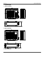
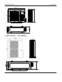
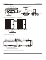
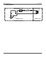
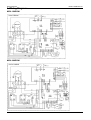
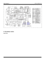
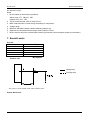
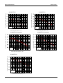
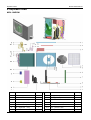
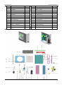
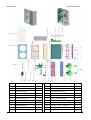
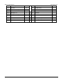
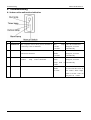
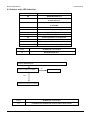
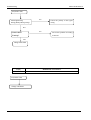
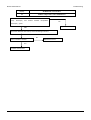
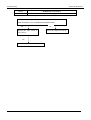
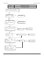
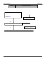
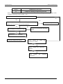
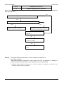
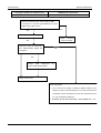
MCAC-UTSM-2007-01
Outdoor Units
Part 3
Outdoor Units
1. Dimensions……………………………………………………………………90
2. Service Space…………………………………………………………………92
3. Piping Diagrams………………………………………………………………93
4. Wiring Diagrams……………………………………………………………94
5. Operation Limits………………………………………………………………96
6. Electric Characteristics……………………………………………………97
7. Sound Levels………………………………………………………………98
8. Exploded View………………………………………………………………100
9. Troubleshooting……………………………………………………………106
Outdoor Units
89
Dimensions
MCAC-UTSM-2007-01
1. Dimensions
1.1. MOU-18HRDN1
1.2 MOU-24HRDN1
1.3 MOU-36HRDN1
90
Outdoor Units
MCAC-UTSM-2007-01
1.4 MOU-48HRDN1
Outdoor Units
Dimensions
MOU-60HRDN1
91
MCAC-UTSM-2007-01
Service Space
2 Service Space
Obstacle
>30cm
Air inlet
>30cm
>60cm
(Wall or obstacle)
Fix with bolt
Air inlet
Maintain channel
>200cm
>60cm
Air outlet
Deep foundation
Necessary width
600mm is necessary between 2 outdoor units
Distance between foot bolts
D
1000
D
12X20 elliptical hole
Regarding D, E please refer to outline and dimension of outdoor unit
92
Outdoor Units
MCAC-UTSM-2007-01
Piping System
3. Piping Systems
outdoor heat exchanger
condensor temp. sensor
Throttle capiliary
T3
T4
muffle
ambient temp. sensor
High pressure valve
stop valve
filter
EXV
filter
Indoor heat
exchanger
T1
Room temp. sensor
stop valve
T2
evaporator temp. sensor
4-way valve
discharge temp. sensor
T5
Low pressure valve
accumulator
compressor
Outdoor Units
Outdoor unit
Indoor unit
93
Wiring Diagrams
MCAC-UTSM-2007-01
4. Wiring Diagrams
MOU-18HRDN1
MOU-24HRDN1
94
Outdoor Units
MCAC-UTSM-2007-01
Wiring diagrams
MOU-36HRDN1
MOU-48HRDN1
Outdoor Units
95
Wiring Diagrams
MCAC-UTSM-2007-01
MOU-60HRDN1
5. Operation Limits
Heat pump
96
Outdoor Units
MCAC-UTSM-2007-01
Operation Limits
Heating
Cooling
43
40
35
30
10
5
5
0
-5
0
-5
-10
-15
-15
5
10
15
20
25
Range for continuous
operation
15
10
Range for
intermittent operation
20
15
Outdoor temperature(℃ WB)
Range for continuous operation
Outdoor temperature(℃ DB)
25
Range for intermittent operation
27
10
15
20
25
30
30
Indoor temperature(℃ DB)
Indoor temperature(℃ WB)
Note: These figure assume the following operating
condition:
Equivalent Pipe length: 7.5m,
Height difference: 0m.
6. Electric Characteristics
Units
Model
Power Supply
Compressor
Outdoor fan motor
Power
Hz
Voltage
Min.
Max.
MCA
MFA
MSC
RLA
MOU-18HRDN1
50
220~240V
198
255
0A
20A
28A
8A
0.129KW
0.59A
MOU-24HRDN1
50
220~240V
198
255
0A
20A
28A
8A
0.15 KW
0.72A
MOU-36HRDN1
50
380V
342
418
6A
15A
28A
7.8A
0.307KW
1.4A
MOU-48HRDN1
50
380V
342
418
6A
15A
28A
7.8A
0.15KW
0.82A
MOU-60HRDN1
50
380V
342
418
6A
15A
28A
7.8A
0.15KW
0.82A
output
FLA
Symbols:
MCA: Min. Circuit Amps.
TOCA: Total Over –Current Amps.
MFA: Max. Fuse Amps..
MSC: Max. Starting Current
RLA: Rated Locked Current
Outdoor Units
97
Sound Levels
MCAC-UTSM-2007-01
FLA: Full Load Amps.
Kw: Rate Motor Output
Notes:
1. RLA is based on the following conditions,
Indoor temp. 27℃ DB/19℃ WB
Outdoor temp. 35℃ DB
2. TOCA means the total value of each OC set.
3. MSC means the Max. current during the starting of compressor.
4. Voltage range
5. Maximum allowable voltage variation between phase is 2%
6. Selection wire size based on the larger value of MCA or TOCA
7. MFA is used to select the circuit breaker and the ground fault circuit interrupter (earth circuit breaker).
7. Sound Levels
Over all:
Model
Noise level dB(A)
MOU-18HRDN1
48
MOU-24HRDN1
52
MOU-36HRDN1
54
MOU-48HRDN1
58
MOU-60HRDN1
60
Microphone
Outdoor unit
Heat pump
Cooling only
1.0 m
The point A is in the middle of the whole outdoor panel.
Octave Band Level
98
Outdoor Units
MCAC-UTSM-2007-01
Sound Levels
24,000BTU/H
Sound pressure level dB(0dB=0.0002μ bar)
Sound pressure level dB(0dB=0.0002μ bar)
18,000 BTU/H
Audibility limits of
continuous white
sound
125
250
500
1000
2000
4000
8000
63
125
250
500
1000
2000
Octave band center frequency(Hz)
Octave band center frequency(Hz)
36,000BTU/H (3 phase)
48,000BTU/H (3 phase)
Sound pressure level dB(0dB=0.0002μ bar)
Sound pressure level dB ( 0dB=0.0002μ bar)
63
Audibility limits of
continuous white
sound
Audibility limits of
continuous white
sound
63
125
250
500
1000
2000
4000
8000
4000
8000
2000
4000
Audibility limits of
continuous white
sound
63
125
250
500
1000
8000
Octave band center frequency(Hz)
Octave band center frequency (Hz)
Sound pressure level dB ( 0dB=0.0002μ bar)
60,000BTU/H
Audibility limits of
continuous white
sound
63
125
250
500
1000
2000
4000
8000
Octave band center frequency (Hz)
Outdoor Units
99
Exploded Views
MCAC-UTSM-2007-01
8. Exploded Views
MOU-18HRDN1
No.
100
Part Name
Quantity
No.
Part Name
Quantity
1
Cover
Ass'y
1
15.1 Inlet pipe Ass'y
1
2
rear net frame
1
15.2 Outlet pipe Ass'y
1
3
E-Parts
1
15.3 Condenser
1
4
Front net Ass'y
1
5
Propeller Fan Ass'y
1
16.1 Fourway valve
1
6
Left clapboard Ass'y
1
16.2 Low
pressure valve
1
7
Separate board
1
16.3 Fourway valve coil
1
Box
Ass'y
16
Fourway valve Ass'y
1
Outdoor Units
MCAC-UTSM-2007-01
Exploded Views
8
Chassis Ass'y
1
17
High pressure valve Ass'y
9
inductance up cover
1
17.1 Electrical expansion Valve
1
10
inductance box
1
17.2 Expansion valve coil
1
11
DC inverter compressor
1
17.3 High pressure valve
1
12
Rear Right clapboard Ass'y
1
18
Holder
13
Valve protection cover
1
19
Fan Motor
1
14
Big handle
1
20
Front board
1
15
Condenser Ass'y
1
for
fan
motor
1
1
MOU-24HRDN1
No.
Part Name
1
Cover
2
E-Parts box
Outdoor Units
Ass'y
Quantity
No.
Part Name
Quantity
1
13.1 Electrical expansion Valve
1
1
13.2 Expansion valve coil
1
101
Exploded Views
MCAC-UTSM-2007-01
3
Rear Right clapboard Ass'y
1
4
Back Right clapboard Ass'y
1
14
Valve installation board
1
5
Big handle
1
15
Chassis Ass'y
1
6
Handle
2
16
inductance up cover
1
7
Water collector
1
17
Cover for reactance filter
1
8
Front board
1
18
Condenser Ass'y
1
9
DC inverter compressor
1
18.1 Inlet pipe Ass'y
1
10
Liquid tank
1
18.2 Condenser connection pipe Ass'y
1
11
Suction pipe Ass'y
1
19
Separate board
1
12
Fourway valve Ass'y
1
20
Left clapboard Ass'y
1
12.1 Fourway valve
1
21
Front net Ass'y
1
12.2 Fourway valve coil
1
22
Propeller Fan Ass'y
1
12.3 Low
1
23
Fan Motor
1
1
24
Holder
13
pressure valve
High pressure valve Ass'y
13.3 High pressure valve
for
fan
1
motor
1
MOU-36HRDN1
102
Outdoor Units
MCAC-UTSM-2007-01
No.
Exploded Views
Part Name
Quantity
No.
Part Name
Quantity
1
13.1 High pressure valve Ass'y
1
1
13.2 Electromagnetic coil
1
1
13.3 Electron Throttle Valve
1
Contactor
1
13.4 Filter
2
2.3
Compressor Capacitor
1
2.4
75A inverter module Ass'y
2
14.1 Low
2.5
PCB Ass'y
1
14.2 Fourway valve
1
14.3 Fourway valve coil
1
1
Cover
2
E-Parts
2.1
E-Parts
2.2
Ass'y
Box
Fourway valve Ass'y
pressure valve
1
1
Holder
motor
1
4
Separating board Ass'y
1
15
Discharger pipe Ass'y
1
5
Installation plate for valves
1
16
Oil back capillary
1
6
Propeller Fan Ass'y
1
17
Liquid tank
1
7
Valev protect cover
1
18
Suction pipe Ass'y
1
8
Condenser Ass'y
1
18.1 Pressure controller
1
8.1
Condenser
1
19
Front board Ass'y
1
8.2
Outlet pipe Ass'y
1
20
Left clapboard Ass'y
1
8.3
Inlet pipe Ass'y
1
21
Front net Ass'y
1
9
Fan Motor
1
22
Chassis Ass'y
1
10
Back Right clapboard Ass'y
1
23
Condenser temp sensor
1
11
Rear Right clapboard Ass'y
1
24
Outdoor Temp sensor
1
12
DC inverter compressor
1
25
Discharge temp sensor
1
13
High pressure valve
1
Outdoor Units
fan
14
3
MOU-48HRDN1
for
Ass'y
MOU-60HRDN1
103
Exploded View
No.
104
MCAC-UTSM-2007-01
Part Name
Quantity
No.
Part Name
Quantity
1
Chassis
1
14.1 High Pressure Valve
1
2
E-parts, assy
1
14.2 Electric expansive valve
1
2.1
Main control board
1
14.3 Electric Expansion loop
1
2.2
Contactor
1
14.4 Filter
2
2.3
Compressor capacitor
1
15
Compressor
1
2.4
Inverter control board
1
16
4-way valve subassembly
1
3
Rear net clip
1
16.1 gas valve subassembly
1
4
Cover
1
16.2 Four-way
Valve
1
5
Fan Motor Holder
1
16.3 Four-way
Valve Solenoid
1
6
Fixture,Segregator
1
17
Liquid pipe valve
1
7
Separating board Ass'y
1
18
Capillary
1
Tube
Outdoor Units
MCAC-UTSM-2007-01
Exploded Views
8
Installation plate for valves
1
19
Fluid tank
1
9
Fan motor
2
20
Gas pipe valve
1
10
Condenser
Ass'y
1
20.1 Pressure controller
1
10.1 Condenser
1
21
Cabinet,Front
1
10.2 Outlet pipe, eva
1
22
Guard fan
2
10.3 Input pipes of Evaporator Ass'y
1
23
left holder
1
11
Propeller fan
2
24
Rear net
1
12
Cabinet,Back side
1
24
Condenser temp sensor
1
13
Cabinet,Front Side
1
25
Discharge temp sensor
1
14
High Pressure Valve Ass'y
1
Outdoor Units
105
Troubleshooting
MCAC-UTSM-2007-01
8. Troubleshooting
8.1 Indoor unit’s malfunction indication
No.
Type
Contents
LED Lamp flash
Remarks
1
malfunction
The evaporator sensor check point is abnomal, or
room temp. sensor is abnormal.
Run
lamp
flashes
at2.5Hz.
After the malfunctions
disappear, it resume
automatically.
2
malfunction
Indoor/outdoor unit comunication is abnormal
The timer lamp
flashes
at2.5Hz.
After the malfunctions
disappear, it resume
automatically.
3
malfunction
Condenser sensor check point is abnormal or
outdoor
temp. sensor is abnormal.
All the indoor
alarm
lamps flash at
0.5Hz.
After the malfunctions
disappear, it resume
automatically.
4
malfunction
Water level switch is abnormal
Alarm
flashes
at 2.5Hz.
If the malfunctions can’t
be solved in three min. all
the indoor alarm lamps
flash at 0.5Hz. Turn off
the power to restore.
106
lamp
Outdoor Units
MCAC-UTSM-2007-01
Troubleshooting
8.2 Outdoor unit’s LED indication
Diaplay
Content of malfunction or protection
E0
EEPROM Malfunction
E2
Communication malfunction between outdoor
IC and indoor IC.
E3
Communication malfunction between outdoor
IC and DSP
E4
Malfunction of out ambient temp. sensor
E5
Voltage protection of compressor
P1
High pressure protection
P2
Low pressure protection
P3
Current protection of compressor
P4
Compressor discharge temperature protection
P5
High temp. protection of ourdoor condenser
P6
Module protection or top temp. protection
Malfunction or Protection
Display
EEPROM Malfunction
E0
Install the EERROM again
Does the trouble occur again?
No
Trouble is solved
Yes
Replace the outdoor main board
Outdoor Units
Display
Malfunction or Protection
E2
Communication malfunction between indoor/outdoor units
107
Troubleshooting
MCAC-UTSM-2007-01
E2(outdoor unit)
Check signal wiring
Wrong polarity? Wrong wiring?
Yes
Correct the polarity of the signal
wiring
NO
Shield cable?
Earthing?
Yes
NO
Correct this problem according
to manual
NO
Change main board
Display
Malfunction or Protection
E3
Communication malfunction between DSP/outdoor units
E3(outdoor unit)
Change main board
108
Outdoor Units
MCAC-UTSM-2007-01
Troubleshooting
Display
Malfunction or Protection
E4
T4&T3 temperature sensor malfunction
Is connection to connector of outdoor condenser’s middle
temp.
sensor(T3)
and
outdoor
ambient
temperature
No
sensor(T4) good?
Yes
Repair connector
Yes
Check the resistance of the temp. sensor according to Annex 1
No
Is the resistance normal?
Replace the sensor
Yes
Outdoor main board
Outdoor Units
109
Troubleshooting
MCAC-UTSM-2007-01
Display
Malfunction or Protection
E5
Compressor Voltage protection
Check the voltage of power supply, if the voltage is about 172--265V(Model
18000 and 24000) or 297—458V(Model 36000,48000,60000)
Yes
Replace the filter board or
power board
No
Correct the voltage in this range
No
Replace the outdoor main board
110
Outdoor Units
MCAC-UTSM-2007-01
Troubleshooting
Display
Malfunction or Protection
P1
High pressure protection
Outdoor master unit display P1;
indoor unit alarm lamp flash
slowly
OK
High/low pressure stop valve
opened completely or not?
Error disappear
No
High pressure range
during unit operating is
correct?
No
Drop redundant refrigerant
Yes
No
The
wire
between
pressure switch and
main board works well?
Replace it
Error disappear
Yes
Pressures switch
work well?
piping
(filter,
accumulator), 4-way
and EXV work well?
No
Replace high pressure switch
No
Replace
Error disappear
Error disappear
Yes
Is pipe blocked ? drop
refrigerant , blow pipe ,
recharge with refrigerant。
Outdoor Units
111
Troubleshooting
MCAC-UTSM-2007-01
Display
Malfunction or Protection
P2
Low pressure protection
Outdoor master unit display P2;
indoor unit alarm lamp flash slowly
OK
High/low
pressure
stop valve opened
Error disappear
NO
No
Low
pressure
range
during unit operating is
correct?
Charge refrigerant
Yes
The wire between pressure
switch and main board works
well?
No
Replace wire
Error disappear
Yes
Pressures switch
work well?
No
piping
(
filter 、
accumulator )、 4-way and
EXV work well?
Replace pressure switch
Error disappear
No
Displace
Error disappear
Yes
Is pipe blocked ? drop
refrigerant , blow pipe ,
recharge with refrigerant。
112
Outdoor Units
MCAC-UTSM-2007-01
Troubleshooting
Display
Malfunction or Protection
P3
Compressor current protection
Check the resistance of compressor, normally
No
U and V is 1 ohm
U and W is 1 ohm
V and W is 1ohm
No
Yes
The compressor is defective
No
Check the refrigerant circulation volume and pressure
Yes
Recharge the refrigerant
If refrigerant circulation volume and pressure is OK, change the outdoor main PCB.
Outdoor Units
113
Troubleshooting
MCAC-UTSM-2007-01
Malfunction or Protection
Display
P4
Compressor discharge temperature protection
When Compressor discharge temp. is more than 105°C, the unit will stop, and unit runs again when
Compressor discharge temp. less than 90°C.
Is the Compressor discharge temp. more than 105°C ?
Yes
No
No
Is the wiring connection is right between Compressor discharge
Correct the wiring connection
temp.sensor and PCB according to Wiring diagrams
Yes
No
Replace the Compressor discharge
Is the resistance of remp.sensor is right
temp.
Yes
Replace the outdoor main board
No
Correct the voltage and frequency
Check whether the voltage and
frequency is normal.
Yes
Check whether the refrigerant is
leakage.
Yes
Stop
leaking
refrigerant
116
and
replenish
Outdoor Units
MCAC-UTSM-2007-01
Troubleshooting
Malfunction or Protection
Display
Condensor high temperature protection
When Condensor high temp. is more than 65°C, the unit will stop, and unit runs again when outdoor pipe
temp. less than 52°C.
P5
Yes
Is the Condensor high temp. more than 65°C ?
No
Is the Condensor high temp. sensor right according to the annex 1.
Yes
Replace the outdoor main board
No
Replace the outdoor pipe temp sensor
The outdoor temp.is too high(More
than 43℃)
No
The system is blocked?
Or EXV is invalid?
Yes
Correct the problem or replace the
EXV.
Remark:①Test digital discharge temperature, outdoor condenser temperature T3
② Test system pressure
③ High digital discharge temperature is likely owing to the lack of refrigerant, air leakage or
system blockade. Check the above items respectively to solve the problem.
③ Condensor high temperature protection owes to the overcharge of refrigerant, air leakage or bad
ventilation and heat-emission conditions.
Outdoor Units
115
Troubleshooting
MCAC-UTSM-2007-01
Display(LED flashes for thirteen times)
Malfunction or Protection
P6
Module protection
Check the connectors CN4, CN1 in outdoor PCBs
Is connection to connector good?Whether the input
voltage range is 380—415V?
No
Yes
Is the wires to compressor right
Repair
connector
or Correct voltage
Yes
Unplug the wiring to compressor,
then restart,whether display the
No
“P6”again?
Yes
Change
IPM
board.(just
model:36000,48000,60000)
for
Change main board
Check compressor
1.
Turn on the unit in cooling or heating in different season, use a
frequency meter to test the frequency in one of the three wires to
compressor, if there is frequency in wires, but compressor do not
run, the compressor is defective.
2. Between U,V,W three terminals , the resistance is ~1 Ώ.
116
Outdoor Units