1
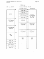
77314 DISK
I/~
BOARD SOFTWARE GUIGF
supplementing
MMSCP/M 2.23 USER1S MANUAL
for the
HEATH/ZENITH Z89 DIGITAL COMPUTER
. support i ng
CORVUS 5, 10, and 20 MByte Winchester Drives
REMEX 8-inch Floppy Disk Subsystems (Z47)
Revised 6/12/81
(c) 1981
Magnolia Microsystems, Inc.
2812 Thorndyke Avenue West
Seattle, WA 98199
(206) 285-7266
(800) 42~-2841
All information in this document is PROPRIETARY to Magnolia Micrbsystems
and is furnished to the user exclusively for use with hardware and sa.f-tware.,
purchased from Magnolia Microsystems.
All software furnished with the I/O board is PROPRIETARY to-Magndl~a
Microsystems and/or Digital Research and is furnished ~or use only with·
hardware purchased from Magnolia Microsystems. Any other use ;s a
vi 01 at; on of the property r; ghts of Ma.gno1 i a Mi crosystems and/or Dfgft.al
Research.
.
.
CP/M is a trademark of Digital Research, Pac'ific' Grove, ·CA.
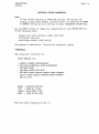
SOFTWARE INSTALLATION
MAGNOLIA MICROSYSTEMS DISK I/O BOARD FOR THE '89
All Magnolia Microsystems disk interface boards use a proprietary
technique to expand the limited number of I/O port addresses available on
the 189. This allows use of more than the five (3 serial ports, 5" disk,
and 8 11 disk) devices allm·Jed by Heath/Zenith.
l
Softv/are is furnished on 5" 10-sector CP/M media. It can be made available
on 5" or 8" Double Dens i ty med i a for use vii th the MMS Double Dens i ty
controller upon request.
This document describes the installation of special BIOS software modules
into a copy of MMS CP/M 2.2 running on a Heath or Zenith 89 computer. It
is assumed that the computer is already ORG-O CP/M compatible, that is, it
is either:
1.
or 2.
or 3.
Z89-FA or Z89-GA or newer model (check label on back of
computer),
Has had the Heath/Zenith 89-7 Upgrade Kit installed,
(In both of these cases, the PROM at U5l7 will be marked
"444-66")
Has Magnolia Microsystems CP/M Modification Kit installed.
l
Also, the 189 must be running the Magnolia implementation of CP/M 2.2, not
the Heath/Zenith implementation.
If not, purchase either the MMS or Heath/Zenith ORG-O hardware kit
your dealer and install it according to the instructions furnished
Then install MMS CP/M 2.2 according to the instructions in the MMS
USERS GUIDE before proceeding with the installation of the MMS I/O
package and this software.
from
with it.
CP/M
boatd'
Following installation of this I/O board and associated drives, your 189
will have greatly increased disk storage capacity.
Disk I/O Board Software Installation
Page 2
Revised 6/12/81 .
DESIGN OF MAGNOLIA MICROSYSTEMS CP/M FOR THE H/Z89
Magnolia Microsystems implementation of CP/M on the 189 has been specially
designed to allow end users to easily add new types of disk storage to
their machine. The BIOS portion of CP/M (see the Digital Research manuals)
has been implemented in a modular fashion, with 3 types of modules used:
l
1.
2.
3.
BASECPM.COM is a "MOVCPM" program \'ihich has NO disk I/O included
at all.
biosname.HEX is a relocatable BIOS module which can be LINKed into
a MOVCPM file to add a specific type of disk I/O.
bootname.HEX is a re10catable BOOT module which can be LINKed into
a MOVCPM file to allow a specific type of disk drive to be
booted.
A new utility LINK.COM is used to merge these modules together to form the
MOVCPM file which is executed to create the desired system image used to
sysgen a disk.
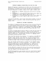
OVERVIEW OF SOFTWARE INTEGRATION
The process of integrating additional types of drives into your Z89 system
is divided between hardware and software installation procedures. The
hardware installation is detailed in a s~parate document, CORVUS and REMEX
software installation is detailed in this document. Install and test MMS
CP/M on your 189 before adding the additional software described in this
document.
The Zenith I/O Decode PROM and Monitor EPROM on the Z89 CPU Logic Board are
replaced by the MMS Decoder and Monitor. These new items provide the
necessary support for data transfer and booting a CP/M system from various
types of system disks. The MMS Decoder and Monitor set does not support
the Heathkit Cassette peripheral device.
After installing the disk drive hardware, it is necessary to get MMS CP/M
software "Up and running" on the new drive. To start, the ne\'J BIOS I/O
module is merged into the current 5.25" mini-floppy CP/M system. This
produces an augmented CP/M system that can recognize and communicate with
the new drive type. Media can then be formatted on the new type of drive.
Next, the new BIOS cold-boot module is merged into the augmented system,
producing a system that is Ine\'l-drive-bootable". This system is written
onto the system tracks of the newly formatted drive. Other utility
programs are also copied from distribution media onto the new drive,
creating a new full-blown) CP/M system disk on the new type of drive.
Finally, MMS CP/M is booted from the new drive using the new system disk.
The increased storage capacity of the new media will make disk-swapping
much less frequent on the Z89 computer system.
The following sections in this document detail the installation of support
software for CORVUS and REMEX drives as currently supported by Magnolia
Microsystems.
Disk I/O Board Software Installation
Page 3
Revised 6/12/81
POWER-ON AND POWER-OFF PROCEDURE
The following power on/off sequence minimizes the probability of having a
power transient cause destruction of data on the additional disk drive:
POWER-ON:
1. Turn-on the Z89 computer.
2. Turn-on the disk drive subsystem(s).
3. Follow the proper Boot procedure.
POWER-OFF:
1. Turn-off the disk drive subsystem(s).
2. Turn-off the Z89 computer.
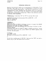
CORVUS SOFTWARE INSTALLATION PROCEDURE
NOTICE:
Whenever installing a new revision of the Corvus modules, BACK
UP YOUR FILES BEFORE INSTALLING THE NEW MODULES. The new
modules may change one or more of the following WHICH MAY CAUSE
LOSS OF DATA:
1. System track allocation on one or more logical drives
2. Directory space allocation on one or more logical drives
1. Boot a copy of MMS CP/M 2.23 from the 5.25
11
drive:
The new MMS EPROM Monitor allows system booting from several different disk
drive systems. The built-in 5.25" mini-floppy drive is assigned the number
0; this number can be entered as an argument to the Boot command to specify
the minifloppy as the boot drive. On resetting the Z89, the CRT screen
command line appears as shown (operator inputs are underlined):
H:
~oot
O(carriage return)
If the number is not entered, the Monitor will default to the drive device
specified by dip switch SW501 on the CPU board. The boot will fail if that
device is not present and bootable. Refer to documentation on the current
Monitor EPROM set for available options.
2. Copy the new CORVUS software onto the 5.25
11
system diskette:
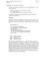
The CORVUS installation procedure requires that the 5.25" system diskette
contain these files:
MOVCPM.COM SETUP.COM
CORVGEN.COM PIP.COM
FILECOPY.COM CLEAR.COM
SYSGEN.COM
LINK.COM·
CBOOT.HEX
and additionally, one of the following disk I/O modules:
CORVl05.HEX
CORV210.HEX
CORV9l0.HEX
CORV320.HEX
CORV920.HEX
(15MB logical device on a 5MB drive)
(24.7MB logical devices on a 10MB drive)
(91.0MB logical. devices ona lO~lB drive)
(36.4MB logical devices on a 20MB drive)
(34.5MB, 5 0.75MB, and 11.8MB logical
devices on a 20MB drive)
Other divisions can be made available on a custom basis.
Extraneous files can be erased to make room for the new CORVUS files; they
can be recovered from your distribution copy of MMS CP/M 2.23 after the
CORVUS disk is configured.
If multiple 5.25" drives are available, PIP.COM may be used to transfer the
CORVUS software onto the 5.25" system vlOrk disk. If only one 5.25" drive
is available, then the single drive utility FILECOPY.COM must be used.
CORVUS Software Installation
6/12/81
Page 5
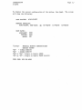
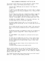
3. Merge CORVnnn.HEX into MOVCPM.COM using LINK.COM:
The CORVUS BIOS I/O module CORVnnn.HEX provides the communication link to
the CORVUS disk drive for CP/M. The command line syntax for the LINK
utility is:
LINK d:source-filename d:destination-filename(cr)
To append the new module, at CP/M command level type:
A)LINK CORV210 MOVCPM(cr)
LINK version 2.231
Link completed
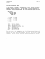
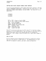
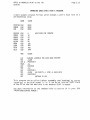
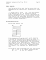
4. Determine CP/M logical drive letters and check CORVUS operating
modes:
To determine the initial CP/M logical drive letters used to reference the
CORVUS partitions, the utility program·SETUP.COM is used to examine the
system program MOVCPM.COM (now containing the CORVUS BIOS I/O module).
SETUP is described in the MMS CP/M 2.23 User·s Guide. At CP/M command
level, type:
A)SETUP MOVCPM(cr)
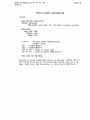
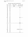
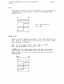
Select the SETUP function IISET LOGICAL/PHYSICAL DRIVE ASSIGNMENTS II • The
display should look similar to the following fragment:
A:
B:
C:
D:
E:
F:
G:
H:
I:
J:
K:
L:
M:
N:
0:
P:
=
=
=
=
=
=
=
=
=
=
=
=
=
=
=
=
(00)
(01)
(02)
(15)
(16 )
(17 )
(18 )
(19 )
(20)
(21)
(22)
(23)
(-- )
(-- )
(-- )
(-- )
FIRST MINI-FLOPPY
SECOND MINI-FLOPPY
THIRD MINI-FLOPPY
CONSTELLATION
CONSTELLATION
CONSTELLATION
CONSTELLATION
CONSTELLATION
CONSTELLATION
CONSTELLATION
CONSTELLATION
CONSTELLATION
••• NOT ASSIGNED •••
••• NOT ASSIGNED •••
••• NOT ASSIGNED •••
••• NOT ASSIGNED •••
At this time you should only have the CORVUS module and the module for your
boot device linked to CP/M. Additional modules may not fit on a mini-floppy
device. In this case, 110: 11 thru IIL:II are the logical drive letters. All
drives may not be present depending on the selected configuration module.
The initial logical drive letters are not fixed, but are determined by the
presence of other disk systems· BIOS I/O modules LINKed into MOVCPM.COM,
and the chronological order of linkage. The number 1115 11 , however, IS FIXED
to the first physical drive of the CORVUS, and can be used as an argument
CORVUS Software Installation
6/12/81
Page 6 .
to the Monitor's Boot command. DO NOT rearrange the logical/physical drive
assignments at this time; press the command key to return to the SETUP
menu.
5. Write the CORVUS-augmented system onto the 5.25 11 system diskette:
Changes or module additions to the system program MOVCPM.COM are not
implemented on the Z89 until the program is executed and relocated, written
onto the system diskette by SYSGEN.COM, and cold-booted back from the
diskette into memory. At CP/M command level, type:
A>MOVCP~1
48 (cr) (enter 32, 48, or 64 dependi ng on system memory size)
CONSTRUCTING 48k Magnolia Microsystems CP/M on HEATH z89 : v2.23
READY FOR IISYSGEN II OR
IISAVE xx CPM48. COM'I
A>SYSGEN(cr)
SYSGEN VERS 2.23
SOURCE DRIVE NAME (OR RETURN TO SKIP)(cr) (system is in memory)
DESTINATION DRIVE NAME (OR RETURN TO RrSrrOT)A
DESTINATION ON A AND TYPE RETURN(cr)
FUNCTION COMPLETE
-DESTINATION DRIVE NAME (OR RETURN TO REBOOT) ••• 00 NOT HIT RETURN!
6. IReset the Z89 and boot the new CORVUS- augmented system:
The 5.25 system diskette nO\'I contains a system capable of communicating
with the CORVUS disk drive after the CORVUS disk has been configured; RESET
the Z89 and cold-boot:
11
H: Boot O(cr)
CORVUS Software Installation
6/12/81
Page 7
7. Make a Copy of MOVCPM.COM and insert the CORVUS cold-boot
routine:
The CP/M system that will eventually reside on the CORVUS must be
"bootable" from the CORVUS drive. This means that ~t must contain the
CORVUS co 1d- boot rout i ne "CBOOT. HEX ". The CORVUS- augmented MOVCP~1. COM,
containing the CORVUS BIOS I/O module and the normal 5.25" mini-floppy
cold-boot routine should be preserved for generating 5.25".mini-floppy
system di sks. The expedi ent maneuver is to make a copy of MOVCPt1.Cm1
before overwriting the mini-floppy cold-boot routine. The utility PIP.COM
is used to make the copy; at CP/M co~mand level, type:
A>PIP CMOVCPM.COM=MOVCPM.COM[V](cr)
A>LINK CBOOT CMOVCPM(cr)
LINK version 2.231
Link completed
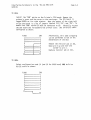
8. Declare the CORVUS as the new cold-boot drive:
The logical/physical drive assignments table within CMOVCPM.COM must be
straightened out so that logical drive "A:II references the first physical
partition of the CORVUS and not the built-in 5.25" mini-floppy drive. The
CP/M system that will boot from the CORVUS must reference the CORVUS as
"A:"; the CP/M system that currently boots off the built-in 5.25"
mini-floppy drive references the built-in 5.25" mini-floppy drive as "A:".
At CP/M command level, type:
A>SETUP CMOVCPM(cr)
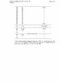
Select the SETUP function "SET LOGICAL/PHYSICAL DRIVE ASSIGNt1ENTS".
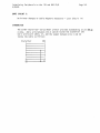
Rearrange the logical/physical drive assignments table so that the first
partition of the CORVUS is logical drive "A:". The resultant assignments
table should look similar to the table reproduced here; compare it to the
table shown in Step 4 preceding.
A:
B:
C:
0:
E:
F:
G:
H:
I:
= (15) CONSTELLATION
= (16)
= (17 )
= (18 )
= (19 )
= (20)
= (21)
= (22)
= (00)
= (01)
K: = (02)
L: = (-- )
J:
M: = ~ -- )
N: = --)
CONSTELLATION
CONSTELLATION
CONSTELLATION
CONSTELLATION
CONSTELLATION
CONSTELLATION
CONSTELLATION
FIRST MINI-FLOPPY
SECOND MINI-FLOPPY
THIRD MINI-FLOPPY
••• NOT ASSIGNED •••
••• NOT ASSIGNED •••
••• NOT ASSIGNED •••
CORVUS Software Installation
6/12/81
Page 8
0: = (--) ••• NOT ASSIGNED •••
P: = (23) CONSTELLATION
Start by setting drive A: to be the CORVUS drive by entering 1115 11 vlithin
the parentheses. This will produce a "DUPLICATE ENTRY" message \·,hich can
be ignored for the moment. Use the move-cursor and data keys of the Z89 to
enter "16", 111711 etc. for as many drives as \'Iere selected. These will
correspond to drives B:, C:, etc. If a module dividing the CORVUS into 9
partitions was selected, it is recommended that the last drive (23) be
entered as P:. This will allow it to be compatible with software which may
be available in the future. Enter the mini-floppy numbers 1100 11 , "01 11 , 110211
in the first three unused locations. Finally, IIHOME II the cursor and sweep
each line entry again: the table should nOH be clear of any error
messages.
Press the command keys to update CMOVCPM.COM to the new assignments table
and to return to CP/M command level.
9. Write the new CORVUS-bootable system onto a CORVUS drive
The system program file CMOVCPM.COM now contains the CORVUS BIOS I/O
module, CORVUS BIOS cold-boot module, and a logical/physical drive
assignments table that refers to the CORVUS as IIA:II. (However, the system
software in force is still using the original logical/physical drive
assignments table observed in step 4.) To create a bootable CORVUS system
type:
A>CMOVCPM 48(cr)
(enter 32, 48 or 64 depending on system memory size)
CONSTRUCTING 48k Magnolia Microsystems CP/M on HEATH z89 : v2.23
READY FOR IISYSGEN II OR
IISAVE xx CP~148.CO~111
A>CORVGEN(cr)
CORVGEN version 2.231
Did you execute MOVCPM ? ( Y or N ) Y (system is in memory)
Do you want to initialize the directories? ( Y or N ) r
Function complete
A>
CORVUS Software Installation
6/12/81
Page 9
10. Clearing the directories
As a new disk contains random data, it is necessary to initialize the
directories for each CORVUS partition v/hen executing CORVGEN for the first
time. CORVGEN does this automatically if requested. If the 'initialize '
option was not elected during CORVGEN, then the CLEAR utility is supplied
to selectively initialize the directories. This program shouldn't be used
on the first CORVUS partition (15), however, as it will erase any system
files present. All directories must be initialized on a new drive. ,To use
the CLEAR program type:
A>CLEAR B:
( B: could be any drive)
11. Copy the 5.25" files onto the CORVUS
The standard MMS CP/M system utilities, such as ED.COM, ASM.COM, STAT.COM,
and PIP.COM can be moved from the 5.25 system mini-floppy to the CORVUS
for user convenience. The utility PIP.COM can be used to facilitate this
transfer; at CP/M command level, type:
11
A>PIP D:=A:*.*[V](cr)
If some extraneous system utilities were deleted from the 5.25" system
mini-floppy to provide work space during the CORVUS software installation
procedure, they can be copied from another 5.25" MMS CP/M 2.23 distribution
diskette after the new CP/M system is booted from the CORVUS.
12. Boot MMS CP/M 2.23 from the CORVUS
The CORVUS should now contain a bootable, CP/M system. The MMS Monitor's
Boot command will get the CP/M system from there if the correct physical
drive number is given after the Z89 is RESET:
H:~oot
48K
A>
15(cr)
Magnolia Microsystems CP/M on HEATH z89 : v2.23
Alternately, the configuration port jumpers can be set as described in
HARDWARE INSTALLATION PROCEDURE so that the system is booted from the
CORVUS drive without entering the number:
H:Boot (cr)
48K Magnolia Microsystems CP/M on HEATH z89 : v2.23
A>
Since the system has been booted from the CORVUS drive, CP/M logical drives
will be referenced as defined in your setup table. (See the
logical/physical drive assignments table of step 8.)
CORVUS Software Installation
6/12/81
Page 10
13. Installing additional bootable systems
Additional partitions (ie. 16-22) may also be bootable if a system is
installed on the appropriate system tracks of the disk. As each partition
appears to CP/M as a separate logical device, each partition may be
SYSGENed. This is done using the SETUP utility and the normal MOVCPM and
SYSGEN procedures. This means a uniquely named MOVCPM file should be
created for each partition to be SYSGENed. The SETUP utility should then be
used to specify the desired partition as the first drive in the
logical/physical drive assignment table. Following this, the unique MOVCPM
should be executed and the resulting system SYSGENed onto the appropriate
partition.
14. Installing other BIOS modules
After testing your CORVUS system operation, you may LINK other BIOS modules
into your CMOVCPM.COM file to alloH access to other types of drives.
This completes the software installation.
REMEX 8
NOTICE:
11
DRIVE SUBSYSTEM SOFTWARE INSTALLATION
This release of the Remex modules uses an Extended Double Density
format with 1024-byte sector blocking/deblocking. This results
in a storage capacity of 1210K bytes on a Double-Sided disk,
compared to the 868K bytes al lowed by early releases of the
module. However, the new and old DO formats ARE NOT COMPATIBLE
and fi 1es must be converted us i ng the procedure descri bed' on page
18.
1. Boot a copy of MMS CP/M 2.23 from the 5.25
11
drive:
The new MMS EPROM Monitor allows system booting from several different disk
drive systems. The built-in 5.25" mini-floppy drive is assigned the number
0; this number can be entered as an argument to the Boot command to specify
the minifloppy as the boot drive. On resetting the Z89, the CRT screen
command line appears as shown (operator inputs are underlined):
H:
~oot
O(carriage return)
2. Copy the new REMEX software onto the 5.25
11
system diskette:
The REMEX installation procedure requires that the 5.25" system diskette
contain these files:
MOVCPM.COM SETUP.COM
FIXBDOS.COM LINK.COM
SYSGEN.COM PIP.COM
FORMATX.COM EIGHTX.HEX
FILECOPY.COM
EBOOTX.HEX
Extraneous files can be erased to make room for the new REMEX files; they
can be recovered from your distribution copy of MMS CP/M 2.23 after the
REMEX 8" system disk is created.
If multiple 5.25" drives are available, PIP.COM may be used to transfer the
REMEX software onto the 5.25" system \'Iork disk. If only one 5.25" drive is
available, then the single drive utility FILECOPY.COM must be used.
3. Fix MOVCPM.COM using FIXBDOS.COM:
For increased I/O speed and disk capacity, the REMEX BIOS module uses
1024-byte sectors and a read/write buffer that is larger that the normal
CP/M sector size (128 bytes). A patch to the CP/M BOOS is required for
sector blocking/deblocking; at CP/M command level, type:
A>FIXBDOS MOVCPM(cr)
FIXBDOS version 1.0
FIX completed
REMEX Software Installation
Revised 6/12/81
Page 12
4. Merge EIGHTX.HEX into MOVCPM.COM using LINK.COM:
The REMEX BIOS I/O module EIGHTX.HEX provides the communication link to the
REMEX di sk dri ve for CP /M. To append the ne\,1 modul e, at CP /M command 1evel
type:
A>LINK EIGHTX MOVCPM(cr)
LINK VERSION 2.23
LINK COMPLETED
5. Determine CP/M logical drive letters and check REMEX operating
modes:
To determine the initial CP/M logical drive letters used to reference the
REMEX drives, the utility program SETUP.COM is used to examine the system
program MOVCPM.COM (now containing the REMEX BIOS I/O module). SETUP is
described in the MMS CP/M User's Guide. At CP/M command level, type:
A>SETUP MOVCPM(cr)
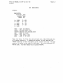
Select the SETUP function "SET LOGICAL/PHYSICAL DRIVE ASSIGNMENTS".
display should look similar to the following fragment:
The
A: = (00) FIRST MINI-FLOPPY
B: = (01) SECOND MINI-FLOPPY
C:
(02) THIRD MINI-FLOPPY
0: = (05) FIRST EIGHT-INCH DRIVE
E: = (06) SECOND EIGHT-INCH DRIVE
F: = (07 ) THIRD EIGHT-INCH DRIVE
G: = (08) FOURTH EIGHT-INCH DRIVE
H: = (-- ) ••• NOT ASSIGNED •••
I : = (-- ) ••• NOT ASSIGNED •••
J: = (-- ) ••• NOT ASSIGNED •••
K: = (-- ) ••• NOT ASS IGNED •••
L: = (-- ) ••• NOT ASSIGNED •••
M: = (-- ) ••• NOT ASSIGNED •••
N: = (-- ) ••• NOT ASSIGNED •••
0: = (-- ) ••• NOT ASSIGNED •••
P: = (-- ) ••• NOT ASSIGNED •••
In this case, "0:" and "E:" are the logical drive letters for the left and
rig ht dr i ve s 0 f the r1 as t erR Er1E X• I f a S1a ve REME Xis ins tall ed, F: and
"G:" will be used to reference it. The initial logical drive letters are
not fixed, but are determined by the presence of other disk systems BIOS
I/O modules LINKed into MOVCPM.COM, and the chronological order of linkage.
The number "5", however, IS FIXED to the left drive of the first REMEX, and
can be used as an argument to the Monitor's Boot command.
II
II
I
DO NOT REARRANGE the logical/physical drive assignments at this time; press
the command key to return to the SETUP menu.
Page 13
REMEX Software Installation
Revised 6/12/81
To check or change the REMEX default (boot-up) operating modes,
select the
SETUP function ISET 8" FLOPPY DEFAULT DENSITY/SIDE CONTROLS I • The display
should look similar to this fragment:
(0)
(1)
= DO/OS
(32)
=
= DO/OS
DO/OS
( ) = DO/OS
(Left drive of Master REMEX - system boot drive)
(Right drive of Master)
(Left drive of Slave REMEX - neednlt be installed)
(Right drive of Slave - neednlt be installed)
"00" stands for double-density; "SO" stands for single-density.
liDS stands for double-sided; "SS" stands for single-sided.
II
The REMEX drive system is normally operated in the double-density,
double-sided modes to take advantage of its large storage capacity. These
are the default (boot-up) modes of the REMEX BIOS software as shipped from
M~1S •
The software modes internal to CP/M control the data format and I/O
transfer to the REMEX drives. SO/OS mode is not allowed. Modes OO/SS or
SO/SS may be specified for a REMEX drive at this time if DO/OS media is not
available, or you do not wish to "risk" using non-certified DO/OS media in
a DO/OS drive. However, REMEX 8 system (bootable CP/M) disks MUST be DO
because of the amount of system track storage required. The Left drive of
the Master REMEX (0) is used for CP/M system booting and should be set only
to DO/OS or OO/SS modes.
11
The mode of a drive (not an inserted disk!) can be inspected at CP/M
command level using the SET.COM utility, which is described in the MMS CP/M
Userls Guide. A drive can be temporarily SET to another mode for a
particular task: e.g. SO/SS mode to read 8" SO/SS Standard Format CP/M
transfer media. This SET utility allows the operator to quickly tailor the
mode of a drive to the formatted mode of a disk, without having to SETUP,
MOVCPM, and re-SYSGEN-ing the system disk. The drive should be SET back to
itls normal mode after the task is complete.
IMPORTANT:
With MMS CP/M, the mode of the drive is the assumed format mode of the disk
(NOT vice-versa as with the Zenith version of CP/M). Each 8 floppy-disk
formatted on a REMEX drive should be marked "00/0S", "OO/SS", or "SO/SS" to
indicate the formatted state of the disk (which, again, reflects the mode
of the drive).·
11
DO NOT LOSE TRACK of the mode of the drives; they are determined by the
CP/M system disk used to boot-up. DO NOT MIX the modes of drives and
disks: before inserting a disk into a drive, tailor the mode of the drive
to the mode of the disk using SET.COM, or by altering the default REMEX
mode table of MOVCPM.COM using SETUP, and re-SYSGEN-ing.
Press the command keys to i mpl ement the dri ve mode changes (i f .any) , and
return to CP/M command level.
Page 14 .
REMEX Software Installation
Revised 6/12/81
6. Write the REMEX-augmented system onto the 5.25
11
system diskette:
Changes or module additions to the system program MOVCPM.COM are not
implemented on the Z89 until the program is executed and relocated, written
onto the system diskette by SYSGEN.COM, and cold-booted back from the
diskette into memory. At CP/M command level, type:
A>MOVCPM 48(cr) (enter 32, 48, or 64 depending on system memory size)
CONSTRUCTING 48k Magnolia Microsystems CP/M on HEATH z89 : v2.23
READY FOR IISYSGEN II OR
IISAVE xx CPM48.COM II
A>SYSGEN(cr)
SYSGEN VERS 2.23
SOURCE DRIVE NAfilE (OR RETURN TO SKIP)M (system is in memory)
DESTINATION DRIVE NAME (OR RETURN TO REBOOT)A
DESTINATION ON A AND TYPE RETURNM
FUNCTION COMPLETE_
DESTINATION DRIVE NAME (OR RETURN TO REBOOT) ••• 00 NOT HIT RETURN!
7. Reset the Z89 and boot the new REMEX-augmented system:
The 5.25 system diskette now contains a system capable of communicating
with the REMEX disk drive; RESET the Z89 and cold-boot:
11
H:
~oot
O(cr)
8. Format 8
11
floppy-disks on the REMEX using FORMATX.COM:
Floppy-disks to be used with CP/M on the REMEX disk drive can now be
formatted using the utility program FORMATX.COM. Obtain certified
double-density, double-sided 8 floppy-disks for the REMEX if possible.
The floppy-disks should be write-enabled (i.e. NOT write-protected).
11
The initial CP/M logical drive letters used to reference the REMEX drives
were determined in step 5, and must be used to specify the REMEX drive used
for formatting. At CP/M command level, type:
A>FORMATX(cr)
MMS FORMAT VERS 2.23
ENTER DRIVE-NAME:, PUSH RETURN --D:(cr) (use appropriate letter)
INSERT BLANK DISK IN DRIVE D: AND PUSH RETURN >(cr)
.
• (format as many floppy-disks as desired)
INSERT BLANK DISK IN DRIVE 0: AND PUSH RETURN >©C (CTRL-C to terminate)
Page 15
REMEX Software Installation
Revised 6/12/81
9. Make a copy of MOVCPM.COM and insert the REMEX cold-boot routine:
The CP/M system that will eventually reside on a REMEX 8 floppy-disk must
be IIbootable from the REMEX drive. This means that it must contain the
REMEX cold-boot routine IIEBOOTX.HEXII. The REMEX-augmented MOVCPM.COM,
containing the REMEX BIOS I/O module and the normal 5.25 mini-floppy
cold-boot routine should be preserved for generating 5.25 mini-floppy
system disks capable of talking to the REMEX drives. The expedient
maneuver is to make a copy of MOVCPM.COM before overv/riting the mini-floppy
cold-boot routine. The utility PIP.COM is used to make the copy; at CP/M
command level, type:
11
ll
11
11
A>PIP MOVCPM8.COM=MOVCPM.COM[V](cr)
A>LINK EBOOTX MOVCPM8(cr)
LINK VERSION 2.23
LINK COMPLETED
10. Declare the REMEX as the new cold-boot drive:
The logical/physical drive assignments table within MOVCPM8.COM must be
straightened out so that logical drive IIA:II references the left drive of
the REMEX and not the built-in 5.25 mini-floppy drive. The CP/M system
that will boot off the left drive of the REMEX must reference the left
drive of the REMEX as IIA: II ; the CP/M system that currently boots off the
built-in 5.25 mini-floppy drive references the built-in 5.25 mini-floppy
drive as IIA:II. At CP/M command level, type:
11
11
11
A>SETUP MOVCPM8(cr)
Select the SETUP function IISET LOGICAL/PHYSICAL DRIVE ASSIGNMENTS II •
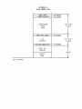
Rearrange the logical/physical drive assignments table so that the left
drive of the REMEX is logical drive IIA:II. The resulting assignments table
should look similar to the table reproduced here; compare it to the table
shown in Step 5 preceding.
A:
B:
C:
D:
E:
F:
G:
H:
I:
=
=
=
=
=
=
=
=
=
(05)
(06 )
(07 )
(08 )
(00 )
(01 )
(02 )
FIRST EIGHT-INCH DRIVE
SECOND EIGHT-INCH DRIVE
THIRD EIGHT-INCH DRIVE
FOURTH EIGHT-INCH DRIVE
FIRST MINI-FLOPPY
SECOND MINI-FLOPPY
THIRD MINI-FLOPPY
(-- ) ••• NOT ASSIGNED •••
(-- ) ••• NOT ASSIGNED •••
0: = (-- ) ••• NOT ASSIGNED •••
P: = (-~ ) ••• NOT ASSIGNED •••
Page 16
REMEX Software Installation
Revised 6/12/81
10. (continued) Declare ••• REMEX •••
Start by setting drive A: to be the first 8" drive by entering "05" within
the parentheses. This will produce a "DUPLICATE ENTRY" message \'/hich can
be ignored for the moment. Use the move-cursor and data keys of the Z89 to
enter "06
"07", and "08" for drives B:, C:, and D:. Enter the
1102" for drives E:, F:, and G:. Finally,
mini-floppy numbers "00 11 , 1101
IIHOr~E II the cursor and sweep each 1 i ne entry aga in:
the table shoul d now be
clear of any error messages.
11
,
11
,
Press the command keys to update MOVCPM8.COM to the new assignments table
and to return to CP/M command level.
11. Write the new REMEX-bootable system onto a 8" floppy-disk:
The system program file MOVCPM8.COM now contains the REMEX BIOS I/O module,
REMEX BIOS cold-boot module, and a logical/physical drive assignments table
that refers to the left drive of the REMEX as "A:II. (HoViever, the system
in control is still using the logical/physical drive assignments table
observed in step 5.) To create a bootable REMEX 8 system floppy-disk,
insert a formatted disk into the left drive of the REMEX, and at CP/M
command level type:
11
A>MOVCPM8 48(cr)
(enter 32, 48 or 64 depending on system memory size)
CONSTRUCTING 48k Magnolia Microsystems CP/M on HEATH z89 : v2.23
READY FOR "SYSGEN" OR
IISAVE xx CPM48.COrvl"
A> SYSGEN (-cr)
SYSGEN VERS 2.23
SOURCE DRIVE NAME (OR RETURN TO SKIP)(cr) (system is in memory)
DESTINATION DRIVE NAME (OR RETURN TO REBOOT)D (t~e REMEXls left drive)
DESTINATION ON D THEN TYPE RETURN(cr)
FUNCTION COMPLETE
-DESTINATION DRIVE NAME (OR RETURN TO REBOOT)(cr) (O.K. to reboot)
A>
-12. Copy the 5.25" files onto the REMEX 8" system floppy-disk:
The standard MMS CP/M system utilities, such as
and PIP.COM can be copied from the 5.25" system
system floppy for user convenience. The utility
facilitate the transfer; at CP/M command level,
ED.COM, ASM.COM, STAT.COM,
mini-floppy to the REMEX 8"
PIP.COM can be used to
type:
A>PIP D:=A:*.*[V](cr)
If some extraneous system utilities were deleted from the 5.25 system
mini-floppy to provide work space during the REMEX software installation
procedure, they can be copied from your 5.25 11 MMS CP/M 2.23 distribution
diskette after the new CP/M system is booted from the REMEX.
11
REMEX Software Installation
Revised 6/12/81
Page 17
13. Boot MMS CP/M from the REMEX
The left drive of the REMEX should now contain a bootable, CP/M system
floppy-disk. The MMS Monitorls Boot command will get the CP/M system from
there if the correct physical drive number is given after the Z89 is RESET:
H:Boot 5{cr)
48k Magnolia Microsystems CP/M on HEATH z89
A>
v2.23
Alternately, the configuration port jumpers can be set as described in
HARDWARE INSTALLATION PROCEDURE so that the system is booted from the REMEX
drive without entering the number:
H:Boot (cr) ,
48k Magnol ia r'~icrosystems CP/M on HEATH z89 : v2.23
A>
Since the system has been booted from the REMEX drive, CP/M logical drives
IIA: and liB: will refer to the 1eft and ri ght disk dri ves of the REMEX,
and logical drive "E:" will refer to the built-in 5.25 mini-floppy used to
install the REMEX software. (See the logical/physical drive assignments
table of step 10.)
II
II
11
If the second and third REMEX Slave Drives are not installed, the
logjcal/physical drive assignments table within the system program
IMOVCPM8.COM" on the REMEX 8" system floppy-disk can be'licompacted
This
would remove entries from the drive assignments table that do not actually
exist. Using the SETUP utility, the unused physical drive numbers 07 and
08 can be deleted or moved "out of the way", and the built-in mini-floppy
drive number 00 can be "tucked" into logical drive "C:". An additional
cycle of executing MOVCPM8 and SYSGEN onto the REMEX 8 system floppy-disk
will implement this housekeeping chore.
ll
•
11
14. Installing other BIOS modules
After testing your REMEX system operation, you may LINK other BIOS modules
into your MOVCPM8.COM file to allow access to other types of drives~
This completes the software installation.
REMEX Software Installation
Revised 6/12/81
Page 18
CONVERSION TO EXTENDED DOUBLE-DENSITY FORMAT
Double-Density files generated using either the old release of MMS CP/M or
Zenith CP/M can be converted to the extended Double-Density format. One
way is to use formatted Single-Density/Single-Sided (SO/SS) media as
intermediate storage for those files that you wish to convert: using the
old CP/M system, copy the Double-Density files onto a SD/SS disk; using
the new REMEX CP/M system, copy the files from the SD/SS disk onto an
(extended) Double-Density disk.
Double-Density => Single-Density => (Extended) Double-Density
For discussion, assume that Double-Density file "SAVE.ME" exists on an OLD
CP/M system disk. A NEW REMEX CP/M system disk has been created on an
(extended) Double-Density disk. To get SAVE.ME into extended density
format, you could:
1.
Boot the OLD CP/M system from drive A:
2.
Make a copy of SAVE.ME on a SD/SS disk in drive B:
A>SET B:SD(cr)
A>FORMAT B:(cr)
A>PIP B:=A:SAVE.ME(cr)
(this will set drive B: to SD/SS)
(insert and format a blank 8" SD/SS disk)
(make a Single-Density copy of the file)
3.
Boot the NEW REMEX CP/M system from drive A:
4.
Make a copy of SAVE.ME" from the SD/SS disk in drive B:
A>SET B:SD(cr)
A>PIP A:=B:SAVE.ME(cr)
(this will set drive B: to SD/SS)
(A: is assumed to extended Double-Density)
The file SAVE.ME is now in extended Double-Density format on drive A:.
APPENDIX A
REMEX DRIVE JUMPER CONFIGURATION
REMEX Intelligent Drive Subsystems (RFS4810 and RFS4820) purchased from
Magnolia Microsystems are shipped configured to operate with the 77314 I/O
board and REMEX BIOS modules. The following data may be useful to service
personnel or others who must configure drives for use with the MMS
interface.
1.
Power-On Sense
Pin 17 (REMEX nomenclature) of connector J1 on the RFS4810 master drive
must be jumpered to +5 volts so that the system software can determine if
the subsystem is turned on or not. (pin 17 connects to conductor 34 in the
ribbon cable to the 189.)
2.
Master Drive (RFS4810) Jumper Plugs
Underlined letters denote the insertion of a shorting plug between posts
indicated:
AA BB CC
= -5 volt regulator disabled (depending on power supply
HJ Y
R ~ ML K
= default to double density
= select as device "0" (CP/M drive A:, use device "111 in a
UT S
VW X
YF G
= door lock enabled
= top head enabled (double-sided drives only)
= track 0 double density
used)
Z47 )
3.
Slave Drive (RFS4820) Jumper Plugs
Underlined letters denote the insertion of a shorting plug between posts
indicated:
ABC
O'EFGHJ
= door lock enabled
= select as device "111 (CP/M drive B:, use device "0 11 in a
KL M
1fP R
= top head enabled (double sided drives only)
= -5 volt regulator disabled (depending on povJer supply
--
Z47 )
used)
4.
Additional Slave Drives
Up to 2 (two) additional Slave drives may be added, jumpered as in #3
above, except select as devices "211 and 113
11
•
5.
Z47 40-Conductor Cable
Only the first 34 wires in the 40 wire Z47 cable are used. If you have a
Z47, simply plug it on (pin 1 to pin 1) to the 34 pin REMEX header.
USER'S MANUAL
CP/H- v2.23+ on Zenith/Heathkit Data Systems Z89
By
MAGNOLIA.
MICROSYSTEMS
MAGNOUA MICROSYSTEMS, INC.
2264 - 15th Avenue West
Seattle, Washington 98119
(206) 285-7266 (800) 426-2841
"Keathkit~
i • • reai.tered trade aame of aeatb CompaDY, BeDtoD Harbor.
"CP/H" i. a trademark of. Digital Re.earcb, Pacific Grave, CA.
"%-80" is a! trademark of ZiloC IDC •• Cupertino. CA. Thi. manual aDd portioD'.
of tbi • • oftware .y.tem are copyright KaCDolia Microly.tem•• IDC.. Seattle.
WA.
MichicaD.
The informatiOD iD thil documeDt il .ubj.ct to chaDge without notice.
Eacb licena. to use this copyriabted material il graDted for a siDgle computer
.Ylte. aad oD1y after executioD aDd returD of the reaiatratioa. to Dicital,
ae •••rch aDd MaCDolia Micro.y.t.... IDe.
KaCnolia Micro.,.t .... IDC. mak•• no warraDty with reaard to thia material,
iDCludiDI. but Dot limited to. implied warraDtie. of merchaDtability aDd
fitDe.. for a particular purpo.e.
Thi.doCUIII~
"a.· produced. all ,s. Z89' UltiDg' 'the KAG.l.c. WAND- word' proce .. iDg
pacta, •• di.tributed for the Z89 by MAgDolia Micro.y.t .... Inc. Proofrelding
wal dOD. with SpellGuard- (a product of Innovative Sof-rwara AlIpl'icat'ioDI.
~eDlo Park. CA).
CoDtaCt KagDolia Micro.y.t .... Iuc.' 'or your local dealer for
more illformatioD aD HAGIC WAHD~ aDd Spellguard-.
Revised April 29, 1981
~Z
\
e \,q, E,\
USER'S MANUAL
CP/Hm v2.23+ on Zenith/Heathkit Data Systems Z89
By
MAGNOLIA MICROSYSTEMS, INC.
2264 - 15th Avenue West
Seattle, Washington 98119
(206) 285-7266 (800) 426-2841
"Heathkit" is a registered trade name of Heath Company, Benton Harbor,
Michigan.
"CP/M" is a trademark of Digital Research, Pacific Grove, CA.
"Z-80" is a trademark of Zilog Inc., Cupertino, CA. This manual and portions
of this software system are copyright Magnolia Microsystems., Inc., Seattle,
WA.
The information in this document is subject to change without notice.
Each license to use this copyrighted material is granted for a single computer
system and only after execution and return of the registrations to Digital
Research and Magnolia Microsystems, Inc.
Magnolia Microsystems, Inc. makes no warranty with regard to this material,
including, but not limited to, implied warranties of merchantability and
fitness for a particular purpose.
This document was produced on a Z89 using the MAGIC WAND m word processing
·package, distributed for the Z89 by Magnolia Microsystems, Inc. Proofreading
was done with SpellGuard m (a product of Innovative Software Applications,
Menlo Park, CA). Contact Magnolia Microsystems, Inc. or your local dealer for
more information on MAGIC WAND m and Spellguard m •
TABLE OF CONTENTS
1.
INTRODUCTION •••••••••••••••••••••••••••••••••••••••••••••••• 1.1
THE CP/M m OPERATING SYSTEM
DISKETTE CARE AND HANDLING
BOOT PROCEDURE
BACKUP PROCEDURE .•.••••••.•..•.••.•••.•.••.••.•.••••••••
DEFINING SYSTEM PARAMETERS
INCREASING SYSTEM SIZE ••••••••••••••••••••••••••••••••••
CREATING A WORKING COpy OF AN APPLICATION DISK ••••••••••
1.1
.............................. 1.2
.......................................... 1.3
1.4
.............................. 1.6
2.
........... . 2.1
NOTES ON MAGNOLIA MICROSYSTEM1S CP/Mm ON THE Z89
2.1 UTILITIES NOT DESCRIBED IN CP/M m MANUALS
FORMAT.COM ••••••••••••••••••••••••••••••••••••••
FILECOPY.COM ••••••••••••••••••••••••••••••••••••
ONECOPY.COM •••••••••••••.•••••••.•••••••••••••••
COPY. COM ••••••••••••••••••••••••••••••••••••••••
SET AUTO. COM •••••••••••••••••••••••••••••••••••••
SET. COM •••••••••••••••••••••••••••••••••••••••••
SETUP .COM •••••••••••••••••••••••••• ~ ••••••••••••
STAT.COM ••••••••••••••••••••••••••••••••••••••••
BASECPM.COM •••••••••••••••••••••••••••••••••••••
FIXMSOFT.COM •••••••••••••••••••.••••••••••••••••
READ.ME
2.2 MODIFYING SYSTEM CONFIGURATION •••••••••••••••••.•••
CHANGING DEVICE DRIVERS •••••••••.•••••••••••••••
CHANGING BAUD RATES FROM A PROGRAM ••••••••••••••
CHANGING THE IIAUTO II IMPLEMENTATION ••••••••••••••
BIOS DETECTION OF ESCAPE SEQUENCES ••••••••••••••
LOGICAL-PHYSICAL DRIVES •••••••••.•••••••••••••••
2.3 DISK TRACK/SECTOR ALLOCATION TABLE •.•••••••••••••••
2.4 MEMORY MAP
.........................................
.........................................
3.
1.11
1.12
2.2
2.2
2.3
2.3
2.4
2.5
2.6
2.7
2.11
2.11
2.12
2.13
2.13
2.13
2.15
2.16
2.17
2.18
2.19
2.21
INTERFACING PERIPHERALS TO THE Z89 AND CP/M m • • • • • • • • • • • • • • • •
DIABLO 630
DIABLO 1640/1650
NEC 5510/5520 •••••••••••••••••••••••••••••••••••••••••••
TI 810 ..................................................
3.1
3.1
3.2
3.2
3.3
TI 820 ••••••••••:•••••••••••••••••••••••••••••••••••••••• 3.3
H14
3.4
EPSON MX - 8a ............................................ . 3.4
QUME SPRINT 5 •••••• ~ •••••••••••••••••••••••••••••••••••• 3.5
STARWRITER •••••••••••••••••••••••••••••••••••••••••••••• 3.5
...............................................
........................................
.....................................................
APPENDIX A - BIOS MEMORY MAP •••••••••••••••••••••••••••••••••••• A.
APPENDIX B - RESERVED LOCATIONS IN PAGE ZERO
Revised April 29, 1981
....................
B.
INTRODUCTION
TO
m
THE CP/M OPERATING SYSTEM
CP/M is a "Control Program for Microcomputers"; a software system designed
to record and retrieve programs and data on floppy disks. It consists of a
collection of inter-related programs designed to accomplish specific tasks
within the system. CP/M operates with 8080 and Z80 microprocessor and is
largely independent of the design of the computer and floppy disk system.
As a result it has been adopted for use by the majority of computers using
the 8080 and Z80 families of microprocessors and has become a "standard".
Many high level languages and applications software packages have been
designed to run under its control.
Magnolia Microsystems has implemented CP/M on your Z89 to make a~cessible
the wide variety of existing CP/M based software. Computer programs
running under CP/M normally communicate only with the operating system and
need no knowledge of the specific hardware in use. This is what makes
programs written to run under CP/M so unive~sal.
We have endeavored to supply you with all the information you need to get
CP/M running on your computer and to help you understand. the system. If
you are intending to run existing applications packages you should also
read the Digital Research manual entitled "An Introduction to CP/M Features
and Facilities". It will probably not be necessary to concern yourself
with the other CP/M manuals to run applications programs. However, if you
intend to do your own programming you should spend time with all six of the
of the manuals (Introduction, DDT, Interface, System Alteration, ED, ASM).
This should be expected to take time and careful study, as well as
experience in using all of the features available.
If you already are using CP/M 1.4 the "CP/M 2.0 User's Guide" will briefly
describe the differences between the two versions.
Note: CP/M uses the symbols "A:", "B:", and "C:" (etc.) to designate disk
drives, in place of the "SYO:", "SY1:", and "SY2:" used by HDOS.
CP/Mm
~s
a registered trademark of Digital Research, Pacific Grove, CA.
INTRODUCTION
3/18/81
Page 1.2
DISKETTE CARE AND HANDLING
A mini-diskette can be WRITE-PROTECTED by placing an opaque sticker over
the notch in the edge of the jacket. All original media (distribution
disks) should always be write-protected. A sheet of opaque stickers (for
write-protecting) is usually furnished with each box of disks.
Always return the diskette to its protective envelope after use. NEVER
touch the diskette through the window slot exposing the magnetic surface.
Do not leave the diskette lying around. Dirt or dust on the diskette could
cause the loss of data. Never leave the diskette lying on the video unit
or near an electric motor since the presence of a magnetic field may cause
loss or scrambling of data.
Use a felt-tip pen to make any notes on the label of the diskette.
ballpoint pen, pencil, or eraser could damage the media inside the
envelope.
Using a
Never remove the diskette from a disk drive compartment with the red 'BUSY'
light on.
Never insert a diskette into the drive before powering the drive up; never
power the drive down while a diskette is still inserted.
Preserve the diskettes by storing them at 10 to 52 degrees Centigrade or
from 50 to 125 degrees Fahrenheit.
INTRODUCTION
3/18/81
Page 1.3
BOOT PROCEDURE
Use this procedure to boot up your CP/M. It assumes that your Z89 is
functioning with at least 32K of RAM.
Note: Throughout this text, as in many programs, (cr) means to press
the RETURN key. Most CP/M programs require a (cr) after characters
are entered from the keyboard to inform the program that operator
input is complete. In this manual also, all operator inputs are
underlined. Thus, in the example below, you would type a B followed
by a RETURN.
Be sure there are NO diskettes in any drive before turning on the power
switch. When the power is cycled the computer should display an "H:" prompt
accompanied by two short beeps. If the prompt does not appear after a
reasonable warm up time press the right shift and reset keys
simultaneously. The prompt should appear accompanied by a single beep. If
not, see Section 8 ("Troubleshooting") in your Heathkit (Zenith)
OPERATIONS/SERVICE MANUAL.
Insert your CP/M m diskette with the label facing the screen (make sure that
the WRITE PROTECT notch on the disk is COVERED so that a system failure
cannot destroy the data on the disk) and gently close the disk drive door.
Type:
H: ~oot(cr)
Type SPACES if HDOS
32K Magnolia Microsystems CP/M on Heath Z89
v2.23
A>
Your CP/Mm system is now up and running. If this is your first use of
the system, back up the distribution diskette. It is most important
that you put your original disk away in a safe place as soon as possible.
It should be left with the write-protect notch covered.
IF YOU MAKE A TYPING ERROR use either (1) CONTROL X to erase the line being
entered and start over (the cursor is returned to the prompt) or (2) use
the BACKSPACE key to remove the erroneous character(s) (the character
deleted will be erased from the screen).
INTRODUCTION
3/18/81
Page 1.4
BACKUP PROCEDURE
This procedure must be used to make a copy of the original distribution
diskette. First a blank 5 1/4" diskette will be formatted (with the FORMAT
program) and then the distribution disk software will be copied onto it.
Boot up your CP/M~ diskette as previously explained. If you have one drive
you FORMAT on drive A:, with two drives you format on drive B:
(substituting B: for A:). At the "A>" prompt type:
A>FORMAT A: (cr)
MMS FORMAT VERS 2.23
INSERT BLANK DISK IN DRIVE A: AND PUSH RETURN >
At this point remove the distribution CP/M disk from drive A: (the drive in
the Z89), insert a new disk into it and push the RETURN key. The program
will format the disk and read each sector to verify that it has been
properly formatted. It then prompts to allow you to format another disk if
desired. If any errors occurred the program will display "FORMAT ERROR: •
". If this occurs try another disk.
INSERT BLANK DISK IN DRIVE A: AND PUSH RETURN>
When the format program has successfully completed, press the CONTROL and C
keys simultaneously (hereafter shown as CC) to return to CP/M~.
Now re-insert your CP/M~ distribution disk in drive A: and copy it onto the
disk you have just formatted. If you have two drives skip to the next page
and use the COpy utility. Otherwise type:
A>ONECOPY (cr)
MMS ONECOPY VERS 2.23
INSERT SOURCE DISK, PUSH RETURN >(insert distribution disk)i££l
INSERT DESTINATION DISK, PUSH RETURN >(insert newly formatted disk)(cr)
(REPEATS)
INSERT SOURCE DISK, PUSH RETURN >(insert distribution disk)(cr)
INSERT DESTINATION DISK, PUSH RETURN >(insert newly formatted disk)(cr)
INSERT SYSTEH DISK, PUSH RETURN >(leave new copy in drive)(cr)
A>
Now put the original distribution disk away in a safe place and use it only
for backup purposes. NEVER remove the WRITE PROTECT tab from a
distribution disk; never write to the disk. This will insure that you
always have a working disk to fall back on if there is a system crash.
INTRODUCTION
3/18/81
Page 1.5
If you have two drives use the COpy utility:
A>COPY A: TO B:(cr)
+COPY VERS 2.23
+SOURCE ON DRIVE A:
+BLANK ON DRIVE B:
+<RET> TO COPY, cc TO EXIT >( cr )
(after disk has been copied, this takes about 1.5 minutes·
for single-sided, single density disks)
+COPY A: TO B:
+SOURCE ON DRIVE A:
+BLANK ON DRIVE B:
+<RET> TO COpy, cc TO EXIT >cC
A>
Now put the original distribution disk away in a safe place and use it only
for backup purposes. NEVER remove the WRITE PROTECT tab from a
distribution disk; never write to the disk. This will insure that you
always have a working disk to fall back on if there is a system crash.
Mark your new disk "32K MMS CP/M for Z89 v2.23+"
"S/N 2-l75-xxxx"
"CDigital Research"
"CMagnolia Microsystems"
as required by your Software License Agreement.
INTRODUCTION
3/18/81
Page 1.6
DEFINING SYSTEM PARAMETERS
NOTE:
If your printer operates at 9600 baud and your '89 contains the
original single sided Siemens mini-disk drives (as delivered by HEATH
or ZENITH) you may go on to the next section, INCREASING SYSTEM SIZE~
Use the SETUP utility to change the configuration of your MOVCPM.COM file
in the following areas:
default baud rates (printer, modem, auxiliary)
mini-floppy step rate
mini-floppy default sided control
The program is menu-driven.
Initiate the program by typing:
A>SETUP(cr)
The screen will initialize to:
SETUP VERSION 2.23
~
•
•
•
•
•
•
DISPLAY CURRENT CONFIGURATION
SET LOGICAL/PHYSICAL DRIVE ASSIGNMENTS
SET BAUD RATES
SET MINI-FLOPPY STEP RATE
SET MINI-FLOPPY DEFAULT DOUBLE SIDED CONTROLS
SET 8" FLOPPY DEFAULT DENSITY/SIDED CONTROLS
EXIT TO CP/M
ENTER = EXECUTE FUNCTION
<UP>
= MOVE UP A LINE
<DOWN> = MOVE DOWN A LINE
HOME
= JUMP TO TOP LINE
With the cursor indicated by the
" "
INTRODUCTION
3/18/81
Page 1.7
To display the current configuration of the system, type (cr).
will show the following:
BOOT ROUTINE:
MINI-FLOPPY
MODULES INSTALLED:
MINI-FLOPPY, STEP RATE:
BAUD RATES:
AUXILIARY:
PRINTER:
MODEM:
The screen
YY
(O)=SS/ST
9600
9600
300
"(n)=xx"
PHYSICAL DRIVE'S DENSITY/SIDED
DEFAULT STATUS
"SD"
= SINGLE DENSITY
"DD"
= DOUBLE DENSITY
"ss" or "DS" = Single or Double SIDED
"ST" or "DT" = Single or Double TRACK density
PUSH <RED> KEY FOR MENU
(l)=SS/ST
(2)=SS/ST
INTRODUCTION
3/18/81
Page 1.8
SETTING PRINTER BAUD RATE
If your printer is running at 9600 baud then go on to "SETTING STEP RATE".
Otherwise move the cursor to ". SET BAUD RATES", using the down-arrow on
the numeric keypad, and push ENTER. The screen should now appear as below:
BAUD RATES:
AUXILIARY:_9600
PRINTER: 9600
MODEM: 300
A
B
C
D
E
= 19200
= 9600
= 4800
2400
= 1200
<RED> =
<BLUE> =
<WHITE>=
=
<UP>
<DOWN> =
=
HOME
F = 600
G = 300
H = 150
I
110
QUIT (NO UPDATE)
END AND UPDATE FILE
RESTART WITH ORIGINAL DATA
MOVE UP A LINE
MOVE DOWN A LINE
JUMP TO TOP LINE
Move the cursor to the PRINTER baud rate line (using the keypad down-arrow)
and enter the letter (A-I) for the desired baud rate. The rate will change
instantly. Push the blue key to set the baud rate and return to the menu.
INTRODUCTION
3/18/81
Page 1.9
SETTING STEP RATE
If your '89 contains the original Siemens disk drives as delivered by
HEATH/ZENITH proceed to "INCREASING SYSTEM SIZE". If you have MPI or other
drives which step faster than 30mS, move the cursor down to the If. SET
MINI-FLOPPY STEP RATE" line and push ENTER. The screen will appear as
below:
STEP RATE: 30mS
<RED> = QUIT (NO UPDATE)
<BLUE> = END AND UPDATE FILE
<WHITE>= RESTART WITH ORIGINAL DATA
Enter the digits for the step rate (leading zero is requir~d) and the
digits will roll left. Only EVEN numbered step rates are allowed, even
though the display number may be odd, it will be rounded up when you push
the BLUE key. For example, to change the steprate to 6mS (for MPI drives)
enter a "0" and then a "6" and the display should read "06mS". Push the
<BLUE> key to update MOVCPM and return to the menu.
INTRODUCTION
3/18/81
Page 1.10
SETTING MINI-FLOPPY DEFAULT DOUBLE SIDED CONTROLS
If you do not have MPI B52 or other double-sided drives proceed to the next
section "INCREASING SYSTEM SIZE". Otherwise move the cursor down to ". SET
MINI-FLOPPY DOUBLE SIDED CONTROLS" and push ENTER. The screen will be as
shown below:
(O)=.§.S/ST
(l)=SS/ST
( 2)=SS/ST
"ss" or "DS" = Single or Double SIDED
"ST" or "DT" = Single or Double TRACK density
<RED> = QUIT (NO UPDATE)
<BLUE> = END AND UPDATE FILE
<WHITE>= RESTART WITH ORIGINAL DATA
MOVE UP A LINE
<UP>
<DOWN> = MOVE DOWN A LINE
= JUMP TO TOP LINE
HOME
Drive (0) is the drive built-into the '89, drive (1) is the first add-on,
and drive (2) is the second add-on. Move the cursor to each drive which is
double-sided and/or double track density and enter the appropriate
indication. Don't forget to push the <BLUE> key to apply these changes to
MOVCPM.
EXIT TO CP/M
Use the "Display Current Configuration" function to verify your entries,
then select the "Return to CP/M" function. The MOVCPM.COM file on your
disk will be updated to reflect your exact system configuration.
INTRODUCTION
3/18/81
Page 1.11
INCREASING SYSTEM SIZE
Magnolia Microsystem's CP/M~ 2.23 is distributed in a 32K version. If you
have 48K or 64K of RAM in your Z89, use MOVCPM.COM to increase the system
size on your operating CP/M diskette. (See page 30, Section 6.9, in the
"INTRODUCTION TO CP/M~ FEATURES AND FACILITIES" manual for additional
information.) If you need to make any changes to the system these should
be done before increasing the system size. Refer to the previous section
on DEFINING SYSTEM PARAMETERS.
A>MOVCPM 48(cr)
(substitute "64" for "48" if you have 64K of ram)
CONSTRUCTING 48K Magnolia Microsystems CP/M on HEATH Z89 : v2.23
READY FOR "SYSGEN" OR
"SAVE xx CPM48.COM"
A>SYSGEN(cr)
SYSGEN VER 2.23
SOURCE DRIVE NAME (OR RETURN TO SKIP)(cr) (system is in memory from MOVCPM)
DESTINATION DRIVE NAME (OR RETURN TO REBOOT)A
DESTINATION ON A THEN TYPE RETURN(cr) (48K CP/M system is written to disk)
FUNCTION COMPLETE
DESTINATION DRIVE NAME (OR RETURN TO REBOOT) DO NOT press Return; instead
wait for busy light to go out, press "SHIFT" and "RESET" together, then
cold boot the new system:
H: ~.oot(cr)
Type SPACES if HDOS
48K Magnolia Microsystems CP/M on HEATH Z89
A>
v2.23
You now have a working copy of 48K CP/M. Mark your disk "48K", and make a
back-up copy of your 48K system disk for safety.
INTRODUCTION
3/18/81
Page 1.12
CREATING A WORKING COpy OF AN APPLICATION DISK
Use this procedure to create a "bootable", working copy of any additional
distribution disks that you purchase. ALWAYS keep distribution disks WRITE
PROTECTED, so that you have a good copy if your system crashes.
First, make a working copy of your new distribution disk using "ONECOPY" or
"COpy A: TO B:" as shown above. Always place the required copyright
notices on all copies that you make, and make copies only for your own use.
Return the distribution copy to a safe storage place.
Then use SYSGEN to place a copy of your CP/M system on the working disk:
A>SYSGEN(cr)
SYSGEN VER 2.23
SOURCE DRIVE NAME (OR RETURN TO SKIP)A
SOURCE ON A THEN PRESS RETURN>(insert working CP/M disk in A:)(cr)
FUNCTION COMPLETE (CP/M system is read into memory from A:)
DESTINATION DRIVE NAME (OR RETURN TO REBOOT)A
DESTINATION ON A THEN TYPE RETURN>(insert new disk in A:)(cr)
FUNCTION COMPLETE (CP/M system has been placed on new disk)
DESTINATION DRIVE NAME (OR RETURN TO REBOOT)(cr)
A>
Now use "FILECOPY" (or "PIP" if you have more than one drive) to place the
CP/M utilities you need on your new disk. These usually will include:
STAT. COM
FORMAT.COM
FILECOPY.COM and/or PIP.COM
ONECOPY.COM or COPY.COM
Instructions for using FILECOPY are given in the next section of this
document. Instructions for using PIP are given in the "INTRODUCTION TO CP/M
FEATURES AND FACILITIES" manual, Section 6.4, page 18.
Be sure to mark all disks containing CP/M with the copyright notices:
o Digital Research
o Magnolia Microsystems
NOTES ON MAGNOLIA MICROSYSTEM1S CP/Mm ON THE Z89
Th is vers i on of CP /W" shou 1d run any "CP /M'" compat i b1e" softwa re wi thout
modification. However, the following should be kept in mind:
Interrupt mode 0 (8080 mode) must be selected if the floppy disk
system is used.
In addition to the WARM and BOOS vectors at 0 and 5, there is a JMP at
8 (RST 1) used for disk timing. See Appendix B for a listing of PAGE 0
assignments.
The mini-floppy disk system uses a delayed-write method to speed disk
access. A write-sector operation is delayed until either a READ
sector, WRITE to a different (256 byte) sector, or the drive-select
times-out. DO NOT REMOVE a disk until the DRIVE SELECT light is OFF.
The MODEM port (ALTERNATE TERMINAL) is initialized to 300 baud.
LP and AUX (DCE) ports are initialized to 9600 baud.
The
The Console Command Processor (CCP) is a file on the disk that is
loaded during cold and ",arm boot. The file is stored under user #31 as
IICCP.SYSII •.
The lK IIFLOPPY DISK RAW (moved from 1400 to F400) is NOT used by the
BIOS in v2.23 and may be accessed by the user in systems with 48K or
1ess.
I
The BIOS RAM requirments vary depending on which disk I/O modules are
LINKed to the main (6 page) BIOS. The mini-floppy module adds 8
pages.
The "AUTO-COMMAND" is only executed at a cold boot but this may be
altered.
For faster boot and SYSGEN access the first 3 tracks (system tracks)
are not recorded on the disk in physical order. This does not make
the disks incompatible with HDOS but HDOS's access to these tracks
will be slower.
The BOOS skews the sectors (tracks 3-75) on the mini-drive in the
following order:
1,2,9,10,17,18,5,6,13,14,3,4,11,12,19,20;7,8,15,16
Whenever ordering software for use under this Standard CP/M m Operating
System make sure that your software vendor knows and understands that you
want the STANDARD version of the software (i.e. ORG = 0100H) not Lifeboat's
modified version (ORG = 4200H).
The Lifeboat Associates Media Format Ordering Code for this ·CP/M m using 5
media is P7. Specify this when ordering from them.
11
NOTES on MAGNOLIA CP /MT" on the 189
Page 2.2
8/18/81
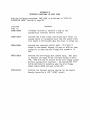
UTILITIES NOT DESCRIBED IN CP/M- MANUALS
These utilities are restricted to use on floppy disk drives.
FORMAT.COM
Formats (or erases) disk.
This utility formats a disk and then reads each sector to verify that
it has been properly formatted. It must be used to format all new
(blank) disks before they can be used with the system.
A>FORMAT B:(cr)
MMS FORMAT VERS 2.23
INSERT BLANK DISK IN DRIVE B: AND PUSH RETURN>
At this point, insert a new disk (or the disk to be erased) into drive
B: and push the RETURN key. Any errors that are detected after
formatting will be reported as follows:
FORMAT ERROR TRACK xx SECTOR yy STATUS zz
Where xx and yy are the track and sector numbers in HEX and zz is the
status in HEX coded as follows:
BITS:
7 6 543 2 1 0
- - - - fm to wp ry
Here "ry" indicates DRIVE READY if "1", "Wp" means the disk is WRITE
PROTECTED, ItO" means a RECALIBRATE (SEEK TRACK 0) failed and "fm"
indicates that the READ/WRITE operation was unsuccessful (if "fm" is
"1", ItO" and "Wp" are "0", and "ry" is "1" then the error was in the
format on the disk).
If any errors occurred the program reports "DISK DID NOT FORMAT!"
before prompting for another disk. Push ©C to return to CP/M (without
rebooting).
NOTES on MAGNOL IA CP /W" on the 189
Page 2.3
8/18/81
FILECOPY.COM
Single drive file copier.
This utility copies a file using only one drive. It will sequentially
prompt the user to "INSERT SOURCE DISK" and fill memory with as much
of the file as will fit, then prompt "INSERT DESTINATION DISK" and
write the block to the new file of the same name. Care must be taken
to keep track of which disk is source and which is destination. When
the file has been transferred the program will prompt "INSERT SYSTEM
DISK" at which time the user puts the disk with the CP/M system on it
into the drive.
A>FILECOPY d:filename.type(cr)
MMS FILECOPY VERS 2.23
INSERT SOURCE DISK, PUSH RETURN >1£rl
INSERT DESTINATION DISK, PUSH RETURN >(cr)
INSERT SYSTEM DISK, PUSH RETURN >1£rl
A>
ONECOPY.COM
Single drive whole-disk copier.
This utility copies the entire contents of a disk using one drive.
Operates like FILECOPY except no filename.type is entered.
A>ONECOPY (cr)
(or ONECOPY d:)
MMS ONECOPY VERS 2.23
INSERT SOURCE DISK, PUSH RETURN >
(etc. )
NOTES on MAGNOLIA CP/Mm on the '89
8/18/81
COPY.COM
Page 2.4
Two-drive repeating disk copier.
This utility is adapted from DIGITAL RESEARCH's "COPY". It uses the
entry parameter liS: TO d:" where "s:" is the source drive name and
"d:" is the destination drive name. This utility will copy the entire
disk (both sides if the drives are double sided).
A>COPY B: TO C:(cr)
+COPY VERS 2.23
+SOURCE ON DRIVE B:
+BLANK ON DRIVE C:
+<RET> TO COPY, ©C TO EXIT
>~
+COPY B: TO C:
+SOURCE ON DRIVE B:
+BLANK ON DRIVE C:
+<RET> TO COPY, ©C TO EXIT >©c
A>
The program \,/i 11 report any "SOURCE" or "DESTINATION" errors and
compares each track after write and reports any "COMPARE" errors. An
error will abort the copy and prompt for new disks (will not return to
CP/M unless ©C is pushed instead of <RET».
NOTES on MAGNOLIA CP /W" on the 189
8/18/81
Page 2.5
The following utilities are not restricted to use on floppy drives.
SETAUTO.COM
Execute a CP/M command line (run a program) on boot.
CP/M can save a command line on a disk which is executed when CP/M is
booted. The utility IISETAUTO II is used to define the command line to
be executed. For example, to cause the program S1200.COM to be
executed automatically when CP/M m boots:
(assume disk to be altered is in B:)
A>SETAUTO B:(cr)
MMS SETAUTO VERS 2.23
ENTER COMMAND LINE:
*S1200(cr)
COMPLETED.
A>
To disable the "AUTO" command, clear the "AUTO" field:
A>SETAUTO B:
MMS SETAUTO VERS 2.23
ENTER COMMAND LINE:
*(cr)
COMPLETED.
A>
NOTE: The command line entered will NOT be converted to uppercase.
If CP/Mm is to recognize the command in uppercase, it must be entered
in uppercase in the SETAUTO command line.
NOTES on MAGNOLIA
CP/M~
on the '89
Page 2.6
8/18/81
SET.COM
Declaring a drive to be Double (or Single) sided on a
temporary basis.
Use SETUP for permanent changes.
This utility limits (or permits) CP/M's use of the second side of a
drive which has been defined in the BIOS as double (or single) sided.
This is useful if a double-sided drive is temporarily added to a
system, or if it is desired to only use the "first" side of a
double-sided drive when duplicating disks to be used on single-sided
drives.
The status of a drive may be display by specifying only the drive
name:
A>SET B:(cr)
%DRIVE B: IS SINGLE SIDED.
A>
To set drive B: to double-sided, type:
A>SET B:DS(cr)
%DRIVE B: SET TO DOUBLE SIDED.
A>
The drive may be set back to single sided by typing "SET B:SS".
The format utility (FORMAT.COM) will check to see if the drive it is
formatting is double sided and if it is, will format both sides of the
disk. Once you are running double sided, all new disks should be
formatted on both sides even if they are only intended for use on a
single sided drive. This way if the disk is mistakenly used in a
double sided drive it will not produce "BAD SECTOR" errors if CP/M
finds the first side full and writes to the second side.
If the second side is accessed and the disk or the drive is not double
sided, a "BAD SECTOR" error will be reported. Type ©C to reboot, then
set the drive to the proper configuration.
NOTES on MAGNOLIA CP/Mm on the 189
8/18/81
SETUP.COM
Page 2.7
Defining system parameters
Use SETUP to change the configuration of your MOVCPM.COM file in the
following areas:
default baud rates (printer, modem, auxiliary)
mini-floppy step rate
mini-floppy default side and track density control
The program is menu-driven and uses some H19 terminal features.
Initiate the program by:
A>SETUP(cr)
The defau 1t fi 1ename i s II~'OVCPMII" and the defau 1t type is IICOM". The
screen will clear and the program will examine the file for current
configurations and validity of data. Then the screen will initialize
to:
SETUP VERSION 2.23
•
•
•
•
•
•
•
DISPLAY CURRENT CONFIGURATION
SET LOGICAL/PHYSICAL DRIVE ASSIGNMENTS
SET BAUD RATES
SET MINI-FLOPPY STEP RATE
SET MINI-FLOPPY DEFAULT DOUBLE SIDED CONTROLS
SET 8" FLOPPY DEFAULT DENSITY/SIDED CONTROLS
EXIT TO CP/M
ENTER = EXECUTE FUNCTION
<UP> = MOVE UP A LINE
<DOWN> = MOVE DOWN A LINE
HOME = JUMP TO TOP LINE
the cursor indicated by the II Move the cursor, using the
right keypad (which is in the shifted mode), to the desired function
and push the ENTER (or RETURN) key. The screen will re-initialize for
the particular function. In general, the RED key returns you to the
menu without updating the file, the WHITE (or GRAY) key restarts the
function with the previous data (nullifies current changes), and the
BLUE key updates the file with the currently displayed information •
. Other keys are defined by the function selected and are displayed on
the lower portion of the screen. Any errors that occur will be
displayed on the top line, above" the menu. The display and a brief
description of each function follows.
~Hth
II
NOTES on MAGNOLIA CP/Mm on the 189
8/18/81
Page 2.8
DISPLAY CURRENT CONFIGURATION
display:
...
BOOT ROUTINE: MINI-FLOPPY
MODULES INSTALLED:
MINI-FLOPPY, STEP RATE: 30
(O)=SS/ST (l)=SS/ST (2)=SS/ST
BAUD RATES:
AUXILIARY: 9600
PRINTER: 9600
MODEM: 300
"(n)=xx"
IISD"
IIDD"
"55 11
IIST"
PHYSICAL DRIVElS DENSITY/SIDED
DEFAULT STATUS
= SINGLE DENSITY
= DOUBLE DENSITY
or "05 11 . = Single or Double SIDED
or IIDT" = Single or Double TRACK Density
PUSH <RED> KEY FOR MENU
The only valid key is RED which returns to the menu. Notice that all
mini-floppy drives (0,1,2) are single-sided and the step rate is 30
.mSec. Note, also, that the printer is initialized to 9600 baud.
NOTES on MAGNOLIA CP /M'" on the 189
8/18/81
Page 2.9
SET BAUD RATES
display:
BAUD RATES:
AUXILIARY: 9600
PRINTER: 9600
MODEM: 300
A = 19200
B = 9600
C = 4800
o = 2400
E = 1200
F = 600
G = 300
H = 150
I = 110
<RED> = QUIT (NO UPDATE)
<BLUE> = END AND UPDATE FILE
<WHITE>= RESTART WITH ORIGINAL DATA
<UP> = MOVE UP A LINE
<DOWN> = MOVE DOWN A LINE
HOME = JUMP TO TOP LINE
Enter the letter (A-I) for the desired baud rate. The displayed rate
will change instantly. To change the printer to 1200 baud use the
<DOWN> arrow key to move the cursor to the printer baud rate line and
push an "E" which is the code for 1200 baud. The rate displayed will
now be 1200. Push the <BLUE> key to update MOVCPM.
NOTES on MAGNOLIA
8/18/81
CP/M~
on the 189
Page 2.10
MINI-FLOPPY STEP RATE
display:
STEP RATE: 30m5
<RED> = QUIT (NO UPDATE)
<BLUE> = END AND UPDATE FILE
<WHITE>= RESTART WITH ORIGINAL DATA
Enter the digits for the step rate (leading zero is required) and the
digits will roll left. To change the step rate to 12m5 enter a 11111
and then a 11211 and the display should read 1112m5 11 • Push the <BLUE>
key to update MOVCPM.
MINI-FLOPPY DEFAULT DOUBLE SIDED CONTROLS
display:
(0)=55/5T
(1)=55/5T
(2)=SS/5T
1155 11 or IIDS II = 5ingle or Double SIDED.
115TII or IIDTII = 5ingle or Double TRACK density
<RED> = QUIT (NO UPDATE)
<BLUE> = END AND UPDATE FILE
<WHITE>= RE5TART WITH ORIGINAL DATA
<UP> = MOVE UP A LINE
<DOWN> = MOVE DOWN A LINE
HOME = JUMP TO TOP LINE
Enter the appropriate indication to single or double sided and/or
single or double track density. If you make any changes donlt forget
to push the <BLUE> key to apply these changes to MOVCPM.
REMEMBER, as indicated by the sign-off message, that the system which is
runni ng has not been affected by thi s procedure. You must run IIr~OVCPMII,
115Y5GEN II your disk, and IICOLD BOOT II to implement any changes made.
NOTES on MAGNOLIA
8/18/81
STAT.COM
CP/M~
on the 189
Page 2.11
Logical/Physical I/O Assignments (IOBYTE).
The current logical/physical I/O assignment options are:
CON:=TTY:
CRT:*
BAT:
UC1:
aux serial port
Z89 console
input=RDR:/output=LST:
modem port
LST:=TTY:
CRT:
LPT:*
UL1:
aux serial port
Z89 console
LP port
modem port
RDR:=TTY:
PTR:*
URI:
UR2:
aux serial port
modem port
Z89 console
LP port
PUN:=TTY:
PTP:*
UP1:
UP2:
aux serial port
modem port
Z89 console
LP port
The default assignments (indicated by * above) may be changed using
STAT.COM as described in IIINTRODUCTION TO CP/M m FEATURES AND
FACILITIES" section 6.1, page 14. For example:
A) STAT LST:=TTY:(cr)
will cause all subsequent output to the LST: device to be routed to
the auxiliary seria) port (alternate printer port) IF it has been
installed on your 189.
See "SYSTEM ALTERATION" Section 6, page 15 for information on
accessing tne IOBYTE from other programs. Also, refer to USER.ASM on
the distribution disk for details on how the IOBYTE is utilized.
BASECPM.COM
This is a renamed MOVCPM file that contains no disk I/O modules. It
will not generate a usable system in its present form, and is
furnished so that we may supply future updates to you more easily.
Further instructions will be furnished with the updates as they are
released.
NOTES on MAGNOL IA CP /W" on the 189
8/18/81
Page 2.12
FIXMSOFT.COM
This utility patches Heath/Zenith copies of various Microsoft products
(such as BASIC-80 and FORTRAN) so that they will operate on 189s that
have the MMS ORG-O CP/M Modification Board installed. Microsoft
products used on 189s without the MMS Board do not have to be patched.
To use the utility type:
A>FIXMSOFT(cr)
FIXMSOFT version 1.1
Insert Heath/Zenith MICROSOFT disk in drive A:
push RETURN (or ©C to EXIT) [insert a copy of your
Microsoft Distribution
fixed: MBASIC
fixed: OBASIC
Disk]~
[The utility will report what
programs are beint patched]
Insert Heath/Zenith MICROSOFT, disk in drive A:
push RETURN (or ©C to EXIT) [insert the disk you booted with]©C
A>
Write protect the patched copy, and consider it your IIMasterll from now
on.
READ.ME
This text file, if present on your distribution disk, will contain
information newer than that included in these printed instructions.
To view the file, type:
A>TYPE READ.ME(cr)
Use IIControl S" to stop and start the di spl ay of the fi 1e on your
terminal.
NOTES on MAGNOLIA CP/M'" on the 189
8/18/81
Page 2.13
MODIFYING SYSTEM CONFIGURATION
»»
REMEMBER!
ANY CHANGES MADE IN "MOVCPM. COM" WILL NOT BE EFFECTIVE UNTIL A
NEW SYSTEM IS CREATED AND SYSGEN'O. SEE "INTRODUCTION TO CP/W"
FEATURES AND FACILITIES" SECTION 6.9 OR PAGE 1.11 FOR THIS
PROCEDURE.
Because the system size will change as more disk I/O modules are added, the
number of pages to save after altering MOVCPM.COM or CPMyy.COM must be
determined by the user. Observe the "NEXT" address given Hhen the file is
loaded under DDT. This address determines the amount that must be saved.
Subtract 0100 from this address and round up to the next 256-byte boundary.
Convert the two most-significant digits to decimal and use this number in
the "SAVE" command. This procedure is also covered on page 2 of "DDT USERS
GUIDE".
CHANGING DEVICE DRIVERS
All device drivers (both Logical and PhYSical) are located in a 512 byte
portion of the BIOS entered via a jump table. The source code for this
"USER AREA" in the BIOS is on the distribution disk as "USER.ASM". A
memory map of the entire BIOS can be found in Appendix A.
Generate (using MOVCPM) an image of CP/Mm for the desired memory size and
save it as CPMyy.COM (where yy is the memory size). Use DDT to find the
starting address of the USER area (the "CONST" console status routine).
Edit USER.ASM~ making your desired changes and setting the starting address
of the USER area, and ASMble it. Then load the CP/Mm image file under DDT
and overlay your USER code using the BIAS given in the assembler listing.
A sample follows for a 48K system:
A>DDT CPM48.COM(cr)
DDT VERS 2.2
NEXT PC
2BOO 0100
-L2000
2000 JMP 1601
2003 JMP 175C
2006 JMP 1900 <--- this is the address we want
NOTES on MAGNOLIA
8/18/81
CP/M~
Page 2.14
on the 189
Edit USER.ASM, including the address found above, then assemble it and get
the BIAS address from the listing:
A>TYPE USER.PRN
OAOO=
;--------------------------------------------------BIAS
;OFFSET FOR DDT
EQU
2000-BIOS
;---------------------------------------------------
(strike any key to stop listing)
And now merge it into CPM48.COM:
A>DDT CPM48.COM
DDT VERS 2.2
NEXT PC
2BOO 0100
-IUSER.HEX
-ROAOO
NEXT PC
2800 0000
-©C
A>
Now SYSGEN the new system:
A>SYSGEN
SYSGEN VER 2.23
SOURCE DRIVE NAME (OR RETURN TO SKIP)(cr) (skip, system is already in
memory)
DESTINATION DRIVE NAME (OR RETURN TO REBOOT)A(cr)
DESTINATION ON A THEN TYPE RETURN(cr)
FUNCTION COMPLETE (new system has been placed on disk)
DESTINATION ON A: THEN TYPE RETURN (after LED is off press SHIFT/RESET)
Re-boot using the new system:
H: ~ootl£!:l
Type SPACES if HDOS
48K Magnolia Microsystems CP/M on Heath Z89
v2.23
A>
Your re-configured system is now up and running.
Or the new image may be saved by typi ng "SAVE xx CPM48 .COW'.
NOTES on MAGNOLIA CP /W" on the 189
8/18/81
Page 2.15
CHANGING BAUD RATES FROM A PROGRAM
A short example program follows which changes a portis baud rate to a
pre-determined value:
NAME
S1200
PRINTER EQU
MODEM EQU
AUX
EQU
OEOH
OD8H
ODOH
B19200 EQU
B9600 EQU
B4800 EQU
B2400 EQU
B1200 EQU
B600
EQU
B300
EQU
B150
EQU
B110
EQU
6
12
24
48
96
192
384
768
1047
ORG
;DIVISORS FOR INS8250
0100H
LXI
H,B1200 ;EXAMPLE FOR 1200 BAUD PRINTER
MVI
A,80H
OUT A PRINTER+3
MOVA
A,L
OUT
PRINTER
MOV
A,H
OUT
PRINTER+1
MVI
A,03H ;NO PARITY, 1 STOP, 8 DATA BITS
OUT
PRINTER+3
RET
;RETURN TO CCP
This program can be called (after assembly and loading) by typing
IS1200"(cr) at the CP/W" prompt ")" or it can be set into the "AUTO" field
of the CCP so that the baud rate is set whenever CP/M~ ;s booted.
For more information on the INS8250 refer to section 14 in your Z89
"OPERATIONS/SERVICE MANUAL".
NOTES on MAGNOLIA CP/Mm on the 189
8/18/81
Page 2.16
CHANGING THE "AUTO" IMPLEMENTATION
To allow the IIAUTO" command 1 i ne to be executed on WARM BOOT as well as
cold, use DDT to patch MOVCPM.COM as follows:
A>DDT MOVCPM.COM(cr)
DDT VERS 2.2
NEXT PC
zzzz 0100
-D2160,216F(cr)
2160 03 00 E5 2A FE 1A 36 C9 21 00 08 22 6E 16 DE 00
-S2160(cr)
2160 03 00
2161 00.
-©C
A>SAVE xx MOVCPM.COM(cr)
••• * .. 6. ~ .... n•••
NOTES on MAGNOLIA
8/18/81
CP/M~
on the 189
Page 2.17
BIOS DETECTION OF ESCAPE SEQUENCES
Provisions have been made in the BIOS which optionally allow the Escape
Sequence codes generated by the terminal portion of the Z89 to be passed to
an application program as a single character. This can greatly simplify
application programs which use the function keys.
This patch must be applied dynamically by the application program and will
be nullified by any WARM BOOT. When active, any special-function key that
generates a two character escape code will be returned from the CONIN
routine as the 7 bit ASCII code of the second character of the sequence,
with the 8th bit set high tp indicate that an escape character immediately
preceded this character. For example, the fl key generates ESC-S and would
be returned as OD3H (ASCII "S" (53H) + bit 7 = OD3H). The ESCAPE key will
still return IBH. Sample code to enable the patch follows:
LHLD
LXI
DAD
MOV
MVI
LXI
DAD
MOV
INX
MOV
XRA
STAX
1
0,5
0
D,M
E,O
H,IFEH
0
E,M
H
D,M
A
0
;GET ADDRESS OF BIOS JUMP TABLE,
;POINT (HL) TO HI-BYTE OF USER AREA ADDRESS
;POINT (DE) TO START OF USER AREA
;ADDRESS WE \'JANT IS 510 BYTES PAST THAT
;(HL) POINT TO ADDRESS
;(DE) CONTAINS THE ADDRESS OF THE BYTE TO PATCH
;(NOP) CODE IS ZERO
;REPLACE (RET) WITH (NOP)
The patch is now active and CONIN will set the MSB on characters
immediately preceded by an ESCAPE. To dynamically disable the patch:
LHLD
LXI
DAD
MOV
MVI
LXI
DAD
MOV
INX
MOV
MVI
STAX
1
0,5
0
D,M
E,O
H,IFEH
0
E,M
H
·D,M
A,OC9H
D
;SAME AS BEFORE •••
;(DE) IS THE ADDRESS OF BYTE TO PATCH·
; (RET) CODE
;CAUSE ROUTINE TO END THERE
The CONIN routine will now pass ESC-sequences as individual (ESC) and
(code) characters.
NOTES on MAGNOLIA
8/18/81
CP/M~
on the '89
Page 2.18
LOGICAL/PHYSICAL DRIVE ASSIGNMENTS
Before a drive is selected the drive number is converted in the SELDSK
routine. SELDSK is called with a logical drive number in register C and
returns the corresponding physical drive number in register C. The table
used for this conversion can be altered using SETUP.COM. The physical
mini-floppy drives are:
o = First (built-in) Mini Floppy
1 = Second Mini Floppy (1st add-on)
2 = Third Mini Floppy (2nd add-on)
Other physical numbers will be assigned to disk types as they are released.
If you are booting from a drive other than the first mini-floppy the
logical-physical drive table in the system being booted must put drive A:
as the disk you are booting so that the CCP file can be loaded.
NOTES on MAGNOLIA CP/M m on the 189
8/18/81
Page 2.19
MINI-FLOPPY TRACK/SECTOR ALLOCATION TABLE
CP/M m module name
Track#
Sector#
00
00
01
02
00
00
00
00
00
00
00
00
00
00
00
00
00
00
00
00
00
00
---01
01
01
01
01
01
01
01
01
01
03
04
05
06
07
08
09
10
11
12
13
14
15
16
17
18
19
20
01
02
'03
04
05
06
07
08
. 09
10
BOOS
01
01
01
01
01
01
01
01
01
01
---02
02
02
02
02
02
11
12
13
14
15
16
17
18
19
20
01
02
03
04
05
06
BIOS
Memory Addres·s
-----------------------------------------------------------2280
2300
Cold start loader
I I
I I
I I
I I
I I
I I
I I
I I
I I
I I
I I
I I
I I
I I
I I
I I
I I
I I
BOOS--------I I
I I
I I
I I
I I
I I
1'1
I I
BOOS
I I
I I
I I
I I
I I
I I
I I
I I
I I
EXTENDED BIOS AREA----I I
I I
I I
I I
BIOS
NOTES on MAGNOLIA CP/Mm on the 189
8/18/81
Page 2.20
BIOS
02
02
02
02
02
02
02
02
02
02
02
02
02
02
07
08
09
10
11
12
13
14
15
16
17
18
19
20
03
1-16
Oirectory*
03
04
17-20
1-20
Oata*
I I
I I
I I
I I
I I
I I
I I
I I
I I
I I
I I
I I
BIOS
I I
I I
I I
39
I I
I I
40
1-20
I I
I I
I I
75
I I
I I
I I
double-sided only --------------------I I
------------------------------------------------------------* The system Console Command Processor. (CCP) is contained on the
disk in a file named CCP.SYS under user #31 and is loaded during a
cold boot into RAM just in front of the BOOS.
NOTES on MAGNOLIA CP/M m on the 189
8/18/81
Page 2.21
MEMORY MAP
Standard CP/M Mode (Org 0)
HOOS Mode (RESET)
64K
32 or 48K System
64K System
----------------- 64K ----------------Floppy ROM
Floppy RAM
Reserved RAM
----------------- 60K
Reserved ROM
RESERVED
System ROM
MAGNOLIA
MICROSYSTEMS
16K Add-On
User' RAM
56K
16K Expansion
User RAM
RESERVED
16K Expansion
·User RAH
16K Expansion
User RAM
----------------- 40K
16K Expansion
User RAM
32K -----------------
-24K
16K Expansion
User RAM
16K Expansion
User RAM
USER
RAM
16K ----------------USER
RAM
----------------- 8K
USER
RAM
Floppy ROM
----------------- 6K
Floppy RAM
----------------- 5K
Reserved RAM
----------------- 4K
Reserved ROM
----------------- 2K
SYSTEM ROM
------------------
0
OK------------------
INTERFACING PERIPHERALS TO THE Z89 AND CP/M m
The standard CP/M physical I/O routines (see USER.ASM on the distribution
disk) are designed to utilize hardware handshaking with peripherals, not
the software protocol used by some HDOS drivers.
The drivers expect to find both RTS (pin 4) and DTR (pin 20) IIHighll before
sending data out to the external device. Either (or both) signal(s) may be
used as a IIBusyll signal to cause the Z89 to stop sending data to the
peripheral device until it is not busy. An open circuit on either pin will
be interpreted as IIBusyll, and CP /W" wi 11 hang up whenever the pri nter is
accessed, so connect unused inputs to a IIHighll level.
The following data will help you connect your printer to the Z89 s LP port
(PI) if you choose to use the standard device drivers furnished with your
CP /M'".
1
If you prefer, you may change the standard device driver by following the
procedure given on page 21. HOWEVER, Magnolia Microsystems can provide no
technical assistance to help you with non-standard device drivers. If you
are only making a minor change, you may wish to use DDT on MOVCPM.COM or on
an image fi 1e of CPMxx. CO~1 to II patch II the code, instead of re- assemb 1i ng
and overlaying it as described. Several customers have reported that
changing the following two bytes has allowed them to use their standard
HEATH (HDOS) cables, but this change HAS NOT BEEN VERIFIED and IS NOT
SUPPORTED by MMS:
LPTSTO:
IN
ANI
CPI
MVI
;Z89 LP PORT OUTPUT STATUS;
PRINTER+6
00110000B
;CTS,DSR --> ANI 00010000
00110000B
;BOTH
--> CPI 00010000
A,O
;CTS ONLY
;JUST ONE
DIABLO 630:
Install a jumper between pins 5 and 6 at location A60 on the HYPRO
Circuit Board. Other pins may already be jumpered. Do not move any
of those.
Use the standard Pin-to-Pin cable furnished with the 630 to connect it
to the Z89.
Interfacing Peripherals to the '89 and MMS CP/M
4/29/81
Page 3.2
DIABLO 1640/1650:
Install the optional IIPrinter Ready Signal per section 3.9.2 in the
XEROX-Diablo 1640-1650 Product Description (document 90412-01, October
1979):
11
move the black wire from pin 3 to pin 2 of the 12-pin connector
on the HPR04 end ( ••• the end of the interface card inside the
printer ••• ) of the Serial I/O cable as follows. Lightly depress the
hold-in tab thru the small hole at pin 3 of the connector, so the pin
can be pulled out of the connector body. Being sure the tab is bent
outward ( ••• enough to secure the pin in the housing ••• ), reinsert the
pin into the connector body at pin 2•••
11 • • •
11
NEe 5510/5520 Spinwriter:
Build an RS-232 adapter as shown:
NEC
1
2
3
4
5
6
7
8
19
20
Z89
1
2
3
4
5
6
7
8
20
OR this change may be effected internally to the NEC. Remove the
printer cover and trace the RS-232 cable back to the interface PC
card. Disconnect the cable at the card and remove the hold-down clip
on the connector housing to expose the hold-in tabs on the connector
pins. Remove the pin from connector position 3. Remove the pin from
connector position 8 and insert it into position 3. Insert the pin
originally in position 3 into position 8. Re-assemble the connector
and re-connect it at the interface PC card. Replace the printer
cover.
ALSO, set the DIP SWITCH just inside the front cover, on the left end:
OFF: 1,3,4,5,6 (S5 off --> Reverse Channel Active High)
ON:
2,7,8
(S7 and S8 on --> 1200 baud)
Interfacing Peripherals to the '89 and MMS CP/M
4/29/81
Page 3.3
TI 810:
Install the "ONB" option on the Printer's CPU board: Remove the
printer's cover and the cover to the card-cage. The CPU board is
tagged GREEN on its right ejector. Near the center of the right half
of the CPU board is a set of jumpers labeled "E4","E5", and "E6". To
enable the "ONB" option E5 must be connected to E6. Carefully re-seat
the CPU board and re-assemble the printer case. Use an RS-232 cable
configured as shown:
TI810
Z89
1-------1
2
2
3
3
4
4
5
6
7
5
6
7
8
20
8
20
Alternately, this same strapping
can be performed at XU1 on the
motherboard of the 810:
Remove the resistor pak at XU1.
Bend pin 8 up and over and
solder to pin 7.
Replace resistor pak at XUl.
TI 820:
Select configuration code 14 (and 28 for 9600 baud) AND build an
RS-232 cable as shown:
3
4
5
6
Z89
1
2
3
-4
5
6
7
7
8
11
8
TI820
1
2
20
Interfacing Peripherals to the 189 and MMS CP/M
4/29/81
Page 3.4
H14:
Strap the H14 internally to provide "NOT BUSY" on pin 15 (as described
in HEATHKIT manual H14/ 595~2172), and build the following RS-232
adapter cable:
H14
Z89
1-------1
2
3
2
3
4
4
5
6
7
5
6
7
Note: NO connection on
pins 5 or 8.
8
8
15-------20-------------20
EPSON MX-80:
Epson is currently supplying two types of serial cards, Model 8140 and
8141. They are supported by selecting 9600 baud, 8-bit words, and NO
parity checking, as follows:
8140:
8141:
Cut option jumpers IJ8/7", IJBl", IJB2", and "JPDS".
Set dip switches 1-1 thru 1-8 all "OFF".
On BOTH cards, add a small jumper wire to the back of the female
RS-232 onBector (for handshaking) connecting pin 4 (RTS) to pin 11
(Printer Ready), or, build the following cable for use between the
MX-80 and 189:
MX-80
1
2
3
4
5
6
7
8
11
20
Z89
1
--2
3
4
5
6
7
8
20
Interfacing Peripherals to the 189 and MMS CP/M
Page 3.5
4/29/81
QUME SPRINT 5:
No Printer changes or Cable Adapters necessary -- just plug it in!
STARWRITER
The CITOH "Stan~ri ter" Oa i sy Wheel pri nter prov ides handshak i ng on pi n ZO
4 only. Add a wire between pins 4 and 20 inside the Starwriter and
use a pin-to-pin cable, or, add the jumper between pins 4 and 20
inside the cable as follows:
Starwriter
Z89
1-------1
2
2
3
3
4
5
4
5
6
6
7
7
8
8
20
'20
~
APPENDIX A
BIOS MEMORY MAP
JUMP TABLE
CONFIGURATION
51 bytes
57 bytes
768 b ytes
3 pa ges
PROPRIETARY
BIOS
CODE
USER JUMP TABLE
21 bytes
DISK I/O
MODULES
It
512 b ytes
2 pag es
I/O
DRIVERS
ESC SEQ PATCH LOC
I~
2 bytes
t
t
var~
BUFFER
AREA
Top of Memory
es
i
APPENDIX B
RESERVED LOCATIONS IN PAGE ZERO
~Jith the follo\'Jing exceptions, PAGE ZERO is as defined in IICP/M 2.0
ALTERATION GUIDE II section 9, page 23.
Locations
from to
OOOSH-OOOAH
Contents
(interupt location 1) Contains a jump to the
interrupt service routine.
sy~tem-clock
OOOBH-OOOCH
Contains the 2 byte (least significant byte first) tic
counter which is incremented each time ~he system clock
tics (every 2 milliseconds when the clock is turned on).
OOODH-OOODH
Contains the interrupt control byte. This byte is
output to the General Purpose I/O port at OF2H for each
system tic or when the mini-floppy disk system is in
use.
OOOEH-OOOEH
Contains the mini-floppy disk control byte. This byte
is normally the image of the last byte output to port
7FH. Some bits may be altered by the mini-floppy system
during a system-clock interrupt. The appropriate bits
can be monitored to determine when the mini-floppy
SELECT and/or MOTOR has been turned off.
0030H-0032H
Contains the interupt service routine for the Double
Density Controller's 1797 IIINTRQII output.
S~ECIAL
APPENDIX C
ENHANCEMENTS TO BOOS and CCP
Magnolia Microsystems has enhanced the BOOS and CCP provided with this copy
of CP/M to add the following features: (Unsophisticated users shouldn't
expect to understand this!)
BOOS Enhancements:
Default USER 0 search: If a file being OPENed is not found on the current
USER number then USER 0 is searched for that file. This means that
utilities only have to exist on USER 0 but can be accessed from all
USER numbers.
Default RIO disk assignment: The last two bytes in the BOOS (addresses
1FFE,lFFF in MOVCPM) are the initial Drive RIO vector. This value is
pre-loaded into the RIO vector whenever a system reset is initiated.
This will force certain drives to be RIO. This value as shipped is
0000 so that no drives are assumed RIO. The least significant bit
corresponds to drive A: and the most significant bit to drive P:. A
disk 1/0 module can access this value to further insure file
protection. The following code in the WRITE-SECTOR routine will
effect this:
INIT$RO
EQU
PATCH-2
WRITE$SECTOR:
LXI
H,MIXER
B,16
LXI
lOA NEWDSK
CCIR
JNZ
ERROR
lHlD INIT$RO
INR C
ROTl
DAD H
OCR C
ROTl
JNZ
JC
ERROR
;address of default RIO vector (relocatable)
;find out what logical drive we are
;search 16 drives
;drive we1re looking for
;Z80 Compare, Increment, Repeat
;error if drive not found
;get RIO vector
;(C) points to proper bit in vector
;rotate'(Hl} left
;count bits
;keep rotating until bit is in carry
;if bit is set we must not write to disk
Deblocking codes: In addition to the deblock-code usually passed in
register C on BIOS disk-write calls, the ACTUAL RECORD number is also
passed in the DE register pair. This makes determining sequential
writes much easier in that the next TRACK and SECTOR numbers do not
have to be calculated before every write.
CCP Enhancements:
Default Command Drive: The last byte in the CCP module (address IIFF in
MOVCPM) is used to determine what drive a command will be loaded from.
If this byte is zero (as shipped) then the current disk is used, as
normally expected. If this byte is 01 thru 10 (hex) then the
indicated drive (OI=A:, 10=P:) is assumed for loading commands. This
allows all utilities to be on only one predetermined drive and not all
working disks. This also enhances the system when used with a hard
disk being accessed by many users (ie, CORVUS Winchester drive with
CONSTELLATION multiplexer).
Disk Reset Command: A new intrinsic command has been included that will
reset the disk system without re-booting. The command is IRES(cr)"
and it has no parameters. It allows all drives to be reset to RjW and
logged-off but it does not require a system disk in A: asl©C" does.