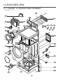
1
Website: http: //www.LGEservice.com
E-mail: http: //www.LGEservice.com/techsup.html
WASHING MACHINE
SERVICE MANUAL
!
CAUTION
READ THIS MANUAL CAREFULLY TO DIAGNOSE
PROBLEMS CORRECTLY BEFORE SERVICING THE UNIT.
MODEL: WM2277H*/WM2077CW
WM2177H*/WM2677H*M
WM2477H*/WM2377C*
WD-11270BD
100
JUL. 2006 PRINTED IN KOREA
P/No.: MFL30599103
101
CONTENTS
1. SPECIFICATIONS .........................................................................................................................3
2. FEATURES & TECHNICAL EXPLANATION ................................................................................ 4
3. PARTS IDENTIFICATION ............................................................................................................ 7
4. INSTALLATION & TEST ............................................................................................................... 8
5. OPERATION ................................................................................................................................11
6. WIRING DIAGRAM/PROGRAM CHART .....................................................................................14
7. TROUBLESHOOTING.................................................................................................................17
7-1. BEFORE PERFORMING SERVICE ...................................................................................17
7-2. QC TEST MODE.................................................................................................................17
7-3. HOW TO CHECK THE WATER LEVEL FREQUENCY ......................................................17
7-4. ERROR DISPLAY ...............................................................................................................18
8. ERROR DIAGNOSIS AND CHECK LIST ....................................................................................20
8-1. DIAGNOSIS AND SOLUTION FOR ABNORMAL OPERATION ........................................20
8-2. FAULT DIAGNOSIS AND TROUBLESHOOTING ..............................................................23
9. DISASSEMBLY INSTRUCTIONS ...............................................................................................32
10. EXPLODED VIEW .....................................................................................................................41
10-1. CABINET & CONTROL PANEL ASSEMBLY....................................................................41
10-2. DRUM & TUB ASSEMBLY................................................................................................42
10-3. DISPENSER ASSEMBLY .................................................................................................43
2
1. SPECIFICATIONS
ITEM
WM2277H*
WD-11270BD
WM2477H*
WM2677H*M
COLOR
WM2077CW
WM2377C*
W: BLUE WHITE, B: BLACK PEARL, S: TITANIUM
POWER SUPPLY
AC 120 V, 60 Hz
PRODUCT WEIGHT
190 lbs. (86 kg)
WASHING
280 W
DRAIN MOTOR
80 W
ELECTRIC POWER
CONSUMTION
WM2177H*
WASH HEATER
REVOLUTION SPEED
1000 W
WASH
SPIN
CYCLES
–
42 rpm
0-1320 rpm
0-1150 rpm
9
7
WASH/RINSE TEMPERATURES
5
SPIN SPEEDS
5
OPTIONS
Prewash, Stain Cycle, Extra Rinse, Rinse+Spin, Delay Wash, Water Plus
CUSTOM PROGRAM
WATER CIRCULATION
Incorporated
Incorporated
–
OPERATIONAL WATER PRESSURE
4.5-145 psi (30-1000 kPa)
CONTROL TYPE
Electronic
WASH CAPACITY [cu. ft.]
3.32 (3.83 IEC)
DIMENSIONS
DELAY WASH
27” (W) X 29 3/4” (D) X 3811/16” (H), 5013/16” (D, door open)
up to 19 hours
up to 12 hours
DOOR SWITCH TYPE
PTC + Solenoid
WATER LEVEL
10 steps (by sensor)
LAUNDRY LOAD SENSING
Incorporated
ERROR DIAGNOSIS
Incorporated
AUTO POWER OFF
Incorporated
CHILD LOCK
Incorporated
RLM ENABLE
0-1000 rpm
Incorporated
–
3
up to 9 hours
2. FEATURES & TECHNICAL EXPLANATION
2-1. FEATURES
■
Direct Drive System
The advanced Brushless DC motor directly drives the drum
without belt and pulley.
■
Tilted Drum and Extra Large Door Opening
Tilted drum and extra large door opening make it possible
to load and unload easily.
■
Water Circulation
Spray detergent solution and water onto the load repeatedly.
Clothes are soaked more quickly and thoroughly during the wash cycle.
Detergent suds are eliminated more easily by the water shower
during rinse cycle. The water circulation system uses both
water and detergent more efficiently.
■
RollerJets
Washing ball enhances wash performance and reduces
damage to clothing. The jets spray and help tumble clothes to enhance
washing performance while maintaining fabric care.
■
Automatic Wash Load Detection
Automatically detects the load and optimizes the washing time.
■
Built-in Heater
Internal heater automatically heats the water to the optimum temperature
on selected cycles.
추가선택, 예약,
■
Child Lock
The Child lock feature prevents children from pressing any buttons
to change the settings during operation.
■
Using the RLM (Remote Laundry Monitor)
The RLM monitors status of your washer and/or dryer. You can plug the
display unit into any power outlet in your home.
The RLM Display Unit can be purchased separately for this washer.
4
2-2. NEURO FUZZY WASHING TIME OPTIMIZATION
To get the best washing performance, optimal time is determined by the water temperature,
the selected washing temperature, and the size of the load.
water
temperature
washing time
selected
washing
temperature
NEUROFUZZY
the best
washing
performance
rinsing time
spin rhythm, time
load
size
SENSING
PROCESSING
DETERMINATION
EFFECT
2-3. WATER LEVEL CONTROL
● This model incorporates a pressure sensor which can sense the water level in the tub.
● The water supply is stopped when the water level reaches the preset level, the washing
program then proceeds.
● Spinning does not proceed until the water in the tub drains to a certain level.
2-4. DOOR CONTROL
● The door can be opened by pulling the door handle whenever washer is not in operation.
● When the cycle is completed, the DOOR LOCKED light will turn off.
● If a power failure has occurred while in operation, the door will unlock after 5 minutes.
● Clicking sounds can be heard when the door is locked/unlocked.
5
2-5. THE DOOR CAN NOT BE OPENED
● While program is operating
● When a power failed and power plug is taken out in operation
● While Door Lock lights turn on.
● White the motor is in the process of intertial rotating, through the operation is paused.
2-6. DOOR LOCKED LAMP LIGHTS
● When the frequency of water level is lower than 22.9 kHz
(It can be canceled when the frequency is more than 23.8 kHz)
● When the temperature inside the tub is higher than 45 °C and water level is not 25.5 kHz
(It can be canceled when the water level is 25.5 kHz or the temperature inside the tub is lower than 40 °C)
2-7. CHILD LOCK
● Use this option to prevent unwanted use of the washer. Press and hold PRE WASH button for 3 seconds to
lock/unlock control.
● When Child lock is set, CHILD LOCK lights and all buttons are disabled except the Power
lock the washer while it is operating.
2-8. WATER CIRCULATION
● When Washing and Rinsing function of shower at the upper part of Gasket.
● When Washing, it continuously operates for 3 minutes and intermittently.
● When Rinsing, it continuously operates after completion of water supply at first rinse.
6
button. You can
3. PARTS IDENTIFICATION
울
란제 리
Water Circulation Nozzle
A
Safety Cover (PLC Moderm)
■ ACCESSORIES
7
4. INSTALLATION & TEST
1⃞ Before servicing, ask the customer what the trouble is.
2⃞ Check the setup (power supply is 120 V AC, remove the transit bolts....).
3⃞ Check with the troubleshooting guide.
4⃞ Plan your service method by referring to the disassembly instructions.
5⃞ Service the unit.
6⃞ After servicing, operate the appliance to see whether it functions correctly.
■ STANDARD INSTALLATION
The appliance should be installed as follows:
REMOVE THE SHIPPING
INSTALL THE APPLIANCE
ADJUST THE
BOLTS
ON A FLAT AND FIRM SURFACE
LEVELING
Remove the 4 shipping bolts
with the supplied wrench.
Turn the leveling feet to adjust
the appliance.
※ Do first lower side to remove easily.
Keep the shipping bolts and
spanner for future use.
Insert the 4 caps
(provided) into the hole.
Turn clockwise to raise;
counterclockwise to lower.
8
■ HOW TO CONNECT THE INLET HOSE
Verify that the rubber washer is inside of the
valve connector.
Tighten the inlet hose securely to prevent leaks.
■ CONNECT THE DRAIN HOSE
· Make sure that the hose is not twisted.
· Avoid submerging the end of the hose.
※ The end of the drain hose should be placed less than 96” from the floor.
■ CONNECT POWER PLUG
· Avoid connecting several electric devices, as
doing so may cause a fire.
· Connect the power plug to the wall outlet.
9
TEST OPERATION
Preparation for
washing.
Press the POWER button.
Connect the power plug to
the outlet.
Connect the inlet hoses.
Check the water heating
function.
Press the Start/Pause
button.
Listen for a click to determine if
the door has locked.
Check the automatic
reverse rotation.
Check the water supply.
MAX
SOFTENER
Press the WASH/RINSE button
and the present temperature will
be displayed.
Check the drain and spin
functions.
Power off and the power on.
Press the SPIN SPEED button.
Press the START/PAUSE button.
Check the spin and drain
functions.
Check if the drum rotates
clockwise and counterclockwise.
Press the
START/PAUSE button.
Listen for a click to determine
if the door is unlocking.
10
Check if water is supplied
through the detergent dispenser.
Water removal
If SVC is needed during check,
remove the remaining water by
pulling out the hose cap.
5. OPERATION
■ WM2277H*/WM2177H*//WM2477H*
SPINSENSE TM
WATER
PLUS
■ WM2077CW//WM2377C*
SPINSENSE TM
WATER
PLUS
■ WM2677H*M
11
• Use this button to turn the power
On/Off.
• This display shows:
a) the estimated time remaining in the
cycle when operating.
b) an error code when an error has been
detected.
• Use this option to prevent
Press and hold PRE WAS
lock/unlock control.
• When Child lock is set, CH
buttons are disabled exce
You can lock the washer w
• Rotate the Cycle selector
knob to select the cycle
designed for different
types of fabric and soil
levels.
• Allows you to store a customized wash cycle for future use.
• Use this button to Start/
Stop the washer.
• To create a Custom Program:
1) Select a cycle.
2) Select the other desired Wash/Rinse Temp., Spin Speed, Soil Level.
3) Select the desired Options.
4) Press and hold the Custom Program button for 3 seconds (2 beep sounds).
The Custom Program is now stored for future use.
• To reuse the program, select Custom Program and press Start/Pause
.
• Se
lo
• To
b
op
• To
b
• Pr
12
ent unwanted use of the washer.
WASH button for 3 seconds to
CHILD LOCK lights and all
xcept the Power
button.
er while it is operating.
• Allows the start of any cycle
to be delayed for 1~12
hours.
• Select a water temperature based on the type of
load you are washing.
• To change the spin speed, press the Spin Speed
button repeatedly to cycle through available
options.
• To change the soil level, press the Soil Level
button repeatedly until the desired setting is on.
• These lights show which portion of
the cycle the washer is operating.
• Lights whenever the door
of the washer is locked.
• The door can be unlocked
by pressing the
Start/Pause
button to
stop the washer.
SPINSENSE TM
WATER
PLUS
• Prewash: Use this option for loads that need pretreatment. It
adds 16 minutes prewash and drain.
• Rinse+Spin: Use this option to rinse and then spin.
• Extra Rinse: This option provides an additional rinse cycle.
• Stain Cycle: Adds time to the wash and rinse cycles for better
stain removal. Automatically provides a rinse.
• Water Plus: Adds extra water to the wash and rinse cycles for
superior results.
• Press repetedly to adjust the volume of the Beeper.
13
6. WIRING DIAGRAM/PROGRAM CHART
■ WM2277H*//WM2477H*
■ WM2077CW//WM2377C*
14
■ WM2177H*
BL GN
/
YL
BN
GN
/
YL
RD
1 2 3
1 2 3
NOISE
FILTER
WH
1 2 3
1 2 3
BK GN
WH
POWER
CORD
■ WM2677H*M
CON3
NA 1 2 3 4 5 6 7 8 9 10 11
DISPLAY PWB
WH 3 2 1
3 21
RD 4 3 2 1
4 3 21
CON3
NA
RD
2 13
2 31 4
2 13
2 31 4
YL BL RD GY WH
2 1 3
2 1 3
SB
BL
1 2 3 4 5 6 7 8 9 10 11 12
1 2 3 4 5 6 7 8 9 10 11 12
BL
1 23 45 6
1 23 45 6
VT SB WH YL RD BL
BN BK YL BL GY WH
1 2 3
1 2 3
WH
SB OR
BL
YL
RD
2 3 1 4
2 3 1 4
YL BL RD GY WH
BL RD
WH
WH
1 2 3 4 5 6 7 8 9 10 11 12 13
1 2 3 4 5 6 7 8 9 10 11 12 13
1 2 3
1 2 3
1 2 3 4 5
1 2 3 4 5
WH
YL RD BL
1 2
1 2
BK
RD
BL
NA
BK
WASHING
HEATER
GN
/
YL
BL
1 2
1 2
1 2
HOT
VALVE
PRE
WASH
MAIN
BLEACH
WASH
INLET VALVE
BALL
SENSOR
THERMISTOR
BK
WH
GND
Ha
Hb
U V W
BK
BL GN
/
YL
1 2
RD
BK
NA
#250TERMINAL
#250TERMINAL+HOUSING
1PIN CONNECTOR
2PIN CONNECTOR
3PIN CONNECTOR
4PIN CONNECTOR
5PIN CONNECTOR
6PIN CONNECTOR
1 3 2
1 3 2
RD
YL BL
SB
PRESSURE
SWITCH
BN
BK
BK
SB
12PIN CONNECTOR
13PIN CONNECTOR
RING TERMINAL GROUND
DRAIN PUMP
WH
YL
1
2
BK GN
CIRCULATION PUMP
RD
BK
BK
8
7
6
5
4
3
2
1
PLC MODEM
1 2 3
1 2 3
WH
P
T
C
DOOR LOCK SWITCH
15
BK
WH
P
T
C
SOLE
NOID
GN
/
YL
WH
RD BK
4 3 2 1
2 3 4 5
3 2 1
3 2 1
YL
BN
NOISE
FILTER
MOTOR
(NOTES)
BL
1 23 4
1 23 4
1 2 3
1 2 3
FUSE
BL RD
BL
CON1
1 2 3 4 5 6 7 8 9 10 11 12
1 2 3 4 5 6 7 8 9 10 11 12 13 1 2 3 4 5 6 7 8 9 10 11 12
1 2 3 4 5 6 7 8 9 10 11 12 13 1 2 3 4 5 6 7 8 9 10 11 12
CON2
CON1
BL
YL
WH
RD
WH
3 21 4 32 1
1 23
1 23
3 21
3 21 4 32 1
1 23
1 23
3 21
MAIN PWB
NA
1 23 45 6
1 23 45 6
CON2
1 2 3 4 5 6 7 8 9 10 11 12 13
POWER
CORD
Cool-down
**Approx.
(Minutes)
*
*
* Wash time is in minutes.
** The total working time will vary with the load size,
water temperature and ambient temperature.
16
7. TROUBLESHOOTING
7-1. BEFORE PERFORMING SERVICE
■ Be careful of electric shock when disconnecting parts while troubleshooting.
■ The voltage of each terminal is 110/120 V AC and DC when the unit is plugged in.
7-2. QC TEST MODE.
The washer must be empty and the controls must be in the off state.
1. Press the SPIN SPEED and SOIL LEVEL buttons simultaneously.
2. Press the Power
button, while the above condition. Then buzzer will sound twice.
3. Press the Start/Pause
button repeatedly to cycle through the test modes.
Number of times the
Start/Pause button is pressed
1)
Check Point
Display Status
None
Turns on all lamps and locks the door.
1 time
Tumble clockwise.
rpm (40~50)
2 times
Low speed Spin.
rpm
3 times
High speed Spin.
rpm
4 times
Inlet valve for prewash turns on.
Water level frequency (25~65)
5 times
Inlet valve for main wash turns on.
Water level frequency (25~65)
6 times
Inlet valve for hot water turns on.
Water level frequency (25~65)
7 times
Inlet valve for bleach turns on.
Water level frequency (25~65)
8 times
Tumble counterclockwise.
rpm (40~50)
9 times
Heater turns on for 3 sec.
Water temperature
10 times
Circulation pump turns on.
Water level frequency (25~65)
11 times
Drain pump turns on.
Water level frequency (25~65)
12 times
Power off and unlock the door.
Turn off all lamps.
: WM2277H*/WM2177H*//WM2477H*
: WM2077CW//WM2377C*
: WM2677H*M
7-3. HOW TO CHECK THE WATER LEVEL FREQUENCY
Press the SPIN SPEED and SOIL LEVEL button simultaneously.
The digits indicate the water level frequency ( x.1 kHz ).
So, for example a display indicating 241: a Water level frequency of 241 x.1 kHz
= 24.1 kHz
17
7-4. ERROR DISPLAY
If you press the START/PAUSE button when an error is displayed, any error exceptd ewill
disappear and the machine will go into the pause status.
In case ofd e
d
,
e
d
,
eif the error is not resolved within 20 sec., or the in case of other errors,
if the error is not resolved within 4 min., power will be turned off automatically and the error code will
blink. But in the case ofd e
, power will not be turned off.
ERROR
1
WATER INLET
ERROR
SYMPTOM
CAUSE
• Correct water level (246) is not reached within 8 minutes
after water is supplied or it does not reach the preset water
level within 25 minutes.
• The load is too small.
• The appliance is tilted.
• Laundry is gathered to one side.
• Non distributable things are put into the drum.
2
IMBALANCE
ERROR
3
DRAIN
ERROR
4
OVER FLOW
ERROR
• Water is overflowing (water level frequency is over 213).
※ If
is displayed, the drain pump will operate to
drain the water automatically.
5
PRESSURE
SENSOR
ERROR
• The SENSOR SWITCH ASSEMBLY is out of order.
6
DOOR OPEN
ERROR
7
HEATING
ERROR
• Not fully drained within 10 minutes.
• Door not all the way closed.
• Loose electrical connections at Door switch and
PWB Assembly.
• The DOOR SWITCH ASSEMBLY is out of order.
• The THERMISTOR is out order.
18
ERROR
8
OVER
CURRENT
ERROR
SYMPTOM
CAUSE
• MAIN PWB ASSEMBLY is out of order.
• Winding in the STATOR ASSEMBLY is short-circuited.
• The connector (3-pin, male, white) in the MOTOR
HARNESS is not connected to the connector
(3-pin, female, white) of STATOR ASSEMBLY.
• The electric contact between the connectors
(3-pin, male, white) in the MOTOR HARNESS
and 4-pin, female, white connector in the MAIN PWB
ASSEMBLY is bad or unstable.
• The MOTOR HARNESS between the STATOR
ASSEMBLY and MAIN PWB ASSEMBLY is cut (open
circuited).
• The hall sensor is out of order/defective.
9
LOCKED
MOTOR
ERROR
10
BALL SENSOR
ERROR
• Loose Ball Sensor Connector.
• Ball Sensor is out of order.
※ Displayed only when the START/PAUSE button is first
pressed in the QC Test Mode.
11
EEPROM
ERROR
• EEPROM is out of order.
※ Displayed only when the START/PAUSE button is first
pressed in the QC Test Mode.
12
POWER
FAILURE
• The washer experienced a power failure.
19
8. ERROR DIAGNOSIS AND CHECK LIST
8-1. DIAGNOSIS AND SOLUTION FOR ABNORMAL OPERATION
SYMPTOM
No power
GUIDE FOR SERVICE CALL
Is the power plug connected firmly to
120 V AC outlet?
YES
Power failure? or Breaker opened?
Is the outlet controlled by a switch?
NO
Visit to service.
Water inlet trouble
Is
displayed?
YES
Is the tap opened?
YES
Is the tap frozen?
NO
Is the water supply shut-off?
NO
Is filter in the inlet valve clogged with
foreign material?
NO
Visit to service.
20
YES
Clean the filter of
inlet valve
SYMPTOM
GUIDE FOR SERVICE CALL
Door error
Was the load too large?
Visit to service.
Drain trouble
Visit to service.
21
SYMPTOM
Suds overflow from the
appliance.
(In this condition, wash and
spin do not operate normally)
GUIDE FOR SERVICE CALL
Is a low-sudsing detergent used?
YES
Is the proper amount of detergent used
as recommended?
LOW-SUDSING
YES
Recommend to reduce the amount
of detergent.
This appliance has an automatic suds sensing function which
prevents overflow.
When excessive suds are sensed, the suds removing
implementations such as drain, water input, pause will operate,
without rotating the drum.
Liquid laundry products do not
flow in.
Is liquid laundry product put in the correct
compartment of the dispenser?
MAX
SOFTENER
YES
Is the cap clogged?
YES
Explain proper use of liquid laundry products.
Clean the compartment.
Visit to service.
22
8-2. FAULT DIAGNOSIS AND TROUBLESHOOTING
CAUTION
1. Be careful of electric shock if disconnecting parts while troubleshooting.
2. First of all, check the connection of each electrical terminal with the wiring diagram.
3. If you replace the MAIN PWB ASSEMBLY, reinsert the connectors correctly.
NO POWER
Is the supplied voltage 110/120 V AC?
NO
Check the fuse or reset
the circuit breaker.
NO
Replace the FILTER
ASSEMBLY (CIRC).
NO
Replace MAIN PWB
ASSEMBLY.
YES
Reconnect.
NO
Replace the MAIN PWB
ASSEMBLY.
YES
Connector
Is the voltage between the 2 FILTER ASSEMBLY
connectors 120 V AC?
YL
WH
WH
BK
YL
BL
BK
YL
RD
RD
BL
SB
YES
WH
BL
BL
WH
RD
SB
Is the LED (1) on?
SB
WH
SB
WH
WH
BL
YL
WH
BL
WH
WH
BK
YL
BL
BK
YL
RD
RD
BL
SB
YES
RD
Are the connectors (2) on the PWB loose?
SB
SB
WH
SB
WH
NO
Is wire of the DISPLAY PWB ASSEMBLY
broken?
YES
Replace DISPLAY PWB ASSEMBLY
or repair wire.
23
VIBRATION & NOISE IN SPIN
Have all the transit bolts and base packing
been removed?
NO
Remove the transit bolts
and Base packing.
NO
Move the washer or
reinforce the floor.
YES
Is the washer installed on a solidly constructed
floor?
YES
Base Packing
Level
Check if the washer is perfectly level as follows:
Check the leveling of the washer with a Level
and check that the washer is stable.
Put an unbalance part (rubber) inside of drum
and start QC test mode and run in high spin
(Refer to section 7-2).
When the machine is spinning in high speed,
verify that it is stable.
If you do not have the unbalance part, put 4.5 to
6.5 lbs (2 to 3 kg) of clothing. Once loaded,
press power, Rinse+Spin and the start/pause
button in sequence.
When the machine is spinning in high speed,
verify that it is stable.
Unbalance Part
Lock
Nut
YES
Higher
Adjustable feet
If it is not stable, adjust feet accordingly. After
the washer is level, tighten the lock nuts up
against of the base of the washer. All lock nuts
must be tightened.
Lower
Adjustable feet
24
If it still has severe vibration and noise, regulate a specific spin speed that generates excessive vibration and
noise as follows:
1) Put an unbalance part (rubber) inside of the drum.
2) Start the QC test mode (Refer to section 7-2).
3) Press Delay Wash button, then ‘
’ is displayed.
4) Press the Spin Speed button repeatedly to select Extra High.
5) Press the Quick Cycle button, the spin speed is displayed.
6) Press the Start/Pause button.
7) Press the Beeper button repeatedly to set spin speed (600, 900, 1020, 1120 rpm) and check if there is vibration
and noise.
8) If there is no vibration and noise, increase the spin speed by pressing Beeper button.
9) If there is vibration and noise, rotate the Cycle selector knob clockwise to reduce the Spin Speed (reduce by 50
and 100 rpm). In case of 600 rpm, it can not reduce the spin speed.
10) If vibration and noise are reduced, press the Quick Cycle button to store (2 beep sounds).
* If you want to return to factory default spin speed setting, repeat above steps except step 9).
25
NO WATER SUPPLY
Is water supply shut-off?
NO
Is the tap opened?
NO
Open the tap.
YES
Check the AIR CHAMBER
and the tube (clogged).
YES
Clean the filter.
NO
Replace the INLET VALVE
ASSEMBLY.
NO
Check electrical connection.
Replace the MAIN PWB
ASSEMBLY.
YES
When you press both SPIN SPEED button and
SOIL LEVEL button simultaneously, is the water
level frequency below 246?
NO
Is the inlet valve filter clogged?
NO
Is resistance between each terminal of INLET
VALVE ASSEMBLY 0.8-1.2 kΩ?
YES
Verify the voltage of the inlet valve connector is
120 V AC.
(Refer to 7-2 QC TEST MODE)
DETERGENT DOES NOT FLOW IN
NO
Is water supplied?
YES
Are receptacles correctly connected to the
terminals of the INLET VALVE ASSEMBLY?
YES
MAX
SOFTENER
NO
Refer to
^NO WATER SUPPLY_
Check the wiring.
Put the detergent in the
correct place.
Has detergent been put in the correct compartment
NO
of the dispenser?
YES
Is the detergent caked or hardened?
26
YES
Clean the dispenser.
LIQUID DETERGENT/SOFTENER/BLEACH DOES NOT FLOW IN
Prewash
Bleach
Hot water
Main wash
MAX
SOFTENER
Bleach cap
SOFTENER
Refer to
^NO WATER SUPPLY_
Is water supplied?
Are the plugs correctly connected to the terminals of
the INLET VALVE ASSEMBLY?
Check the wiring on the
dispenser.
Is liquid detergent/softener/bleach put in the correct
compartment of the drawer?
Put it in the correct
compartment.
Is the liquid detergent/softener/bleach cap clogged?
Clean the Cap and
Container.
MAX
SOFTENER
Softener
cap
Liquid detergent cap
ABNORMAL SOUND
Is the motor bolt loosened?
Secure the bolt.
Is there friction noise coming from the motor?
Replace the STATOR
ASSEMBLY or ROTOR
ASSEMBLY.
27
HEATING WITHOUT WATER
WH
BL
YL
WH
YES
Replace the MAIN PWB
ASSEMBLY.
YES
Repair the DRAIN HOSE
ASSEMBLY.
YES
Remove foreign material.
YES
Reconnect or repair the
connector
YES
Replace the DRAIN
PUMP ASSEMBLY.
NO
Replace the MAIN PWB
ASSEMBLY.
YES
WH
BK
YL
BL
BK
NO
Replace the
SENSOR SWITCH
ASSEMBLY.
YL
RD
RD
BL
SB
When pressing SPIN SPEED and SOIL LEVEL at the
same time after draining, is the water level frequency
255?
When pressing SPIN SPEED and SOIL LEVEL buttons
at the same time while washing, is the water level
frequency between 230 - 243 ?
BL
WH
RD
SB
SB
WH
SB
WH
Check the voltage between two pins while pressing
the POWER button. Is the voltage 120 V AC?
DRAIN MALFUNCTION
Is the drain hose twisted or frozen?
NO
Is the impeller of the drain pump clogged?
NO
Is the connector disconnected, disassembled?
NO
WH
BL
YL
WH
WH
BL
WH
RD
SB
SB
WH
NO
BK
YL
BL
BK
YL
RD
RD
BL
SB
Is the coil of the drain pump too high or low?
(resistance of the coil is 10-20 Ω)
SB
When checking voltage between connectors during
WH
spin, is the voltage 120 V AC as in the figure?
28
WASH HEATER TROUBLE
BL
WH
BL
BK
YL
YL
WH
RD
BK
RD
BL
WH
SB
YL
BL
WH
RD
SB
SB
WH
SB
WH
HEATING CONTINUOUSLY ABOVE
THE SETTING WATER TEMPERATURE
Extra Hot: 70 °C
25
WH
BL
BL
BK
YL
YL
WH
RD
BK
RD
BL
WH
SB
YL
BL
WH
RD
SB
SB
WH
SB
WH
(1)
When checking the THERMISTOR on the tub,
is the THERMISTOR loose?
29
Push the THERMISTOR
tightly to the rubber.
WILL NOT CIRCULATE WATER
Is the impeller of the drain pump clogged?
Hose
Connector
(White)
Hose
YES
Remove foreign material.
YES
Remove foreign material.
YES
Reconnect or repair
the connector.
YES
Replace PUMP MOTOR
ASSEMBLY.
NO
Replace the MAIN PWB
ASSEMBLY.
NO
Are the Hose Connector and/or Hose clogged?
NO
Connector
Is the connector disconnected, disassembled?
NO
Connector
Is the coil of the right side of drain pump open
or short circuited? (Coil R is 18-30 Ω)
NO
BL
WH
BL
YL
WH
BK
YL
BL
BL
WH
RD
WH
SB
RD
BK
YL
RD
SB
When checking voltage between the
connectors during spin, is the voltage 120 V AC,
as the figure?
SB
WH
SB
WH
30
SPIN TROUBLE
Check during spin if the frequency of the water
level is 248 or more.
BL
WH
BL
Check the SENSOR SWITCH
ASSEMBLY or HOSE (Pressure).
If the problem is on the SENSOR
SWITCH ASSEMBLY or the
HOSE, replace the SENSOR
SWITCH ASSEMBLY or the
HOSE.
Press the START/PAUSE button 2 times in QC
Test mode, is the drum spinning at low speed?
Normal
Is it disconnected, or disassembled?
[Red: 3pin (1), NA: 4pin (2)]
Correct the connection.
BK
YL
YL
WH
RD
BK
RD
BL
WH
SB
YL
BL
WH
RD
SB
SB
WH
SB
WH
(1)
(2)
Check the motor connector, Is the resistance of
the terminal the same as the figure?
MOTOR TERMINAL
Replace the STATOR
ASSEMBLY
Resistance of terminal:
- / - / - : About 5 Ω -15 Ω
Replace the MAIN PWB ASSEMBLY
BL
WH
BL
Does the spring of Latch Hook actuate?
Replace Door Assembly.
Is there clicking sound once or twice when the
START/PAUSE button is pressed to start the cycle?
Check the DOOR SWITCH
ASSEMBLY Connector and
MAIN PWB ASSEMBLY
(Red 3 pin, Yellow 4 pin and
white 3 pin connector (1)).
Is DOOR SWITCH ASSEMBLY broken?
Replace the DOOR
SWITCH ASSEMBLY.
BK
YL
YL
WH
RD
BK
RD
BL
WH
SB
YL
BL
WH
RD
SB
SB
WH
SB
WH
31
9. DISASSEMBLY INSTRUCTIONS
Be sure to unplug the machine out of the outlet before disassembling and repairing the parts.
CONTROL PANEL ASSEMBLY
TOP PLATE ASSEMBLY
① Unscrew 2 screws on the back of the top plate.
② Pull the top plate backward and upward as shown.
③ Disconnect the Display PWB Assembly connector
from Trans cable.
④ Pull out the drawer and unscrew 2 screws.
DRAWER
⑤ Lift the left side of the Control Panel Assembly and
pull it out.
CONTROL PANEL ASSEMBLY
DISPLAY PWB ASSEMBLY
⑥ Unscrew the 9 screws from the Control Panel
Assembly.
⑦ Disassemble the Display PWB Assembly.
32
MAIN PWB ASSEMBLY
① Disconnect the POWER connector and SENSOR
SWITCH ASSEMBLY.
② Remove the Protect Cover.
PROTECT COVER
③ Disconnect the connectors.
④ Unscrew 1 screw on the back.
⑤ Disassemble the Main PWB.
33
DISPENSER ASSEMBLY
① Disassemble the top plate assembly.
② Pull out the drawer.
③ Push out the DISPENSER ASSEMBLY after
unscrew 2 screws.
④ Unscrew the nut at the lower part of the dispenser.
⑤ Disassemble the 4 connectors from the valves.
※ Wire Color
① Blue Housing (OR-BK)
② White Housing (WH-BK)
③ Blue Housing (GY-BK)
④ Red Housing (BL-BK)
⑥ Unscrew 2 screws from the back of the cabinet.
NOISE FILTER
① Disassemble two (or three) connectors from
the NOISE FILTER.
② Unscrew a screw from the TOP BRACKET.
34
CABINET COVER
① Unscrew the 4 screws from upper of the canbinet
cover.
② Unscrew the screw from filter cover.
③ Put a flat ( - ) screwdriver or putty knife into the both
sides of the filter cover, and pull it out.
④ Unscrew the screw from the lower side of the cabinet
cover.
35
⑤ Open the door.
⑥ Disassemble the clamp assembly.
⑦ Tilt the cabinet cover.
⑧ Disconnect the door switch connector.
※ NOTE: When assembling the CABINET
COVER, connect the connector.
⑨ Lift and separate the cabinet cover.
⑩ Disassemble the clamp assembly.
⑪ Disassemble the Gasket.
36
DOOR
① Open the door.
② Unscrew the 7 screws from the HINGE COVER.
③ Put a flat ( - ) screwdriver into the openng of the hinge,
and pull out the hinge cover.
④ Unscrew a screw from the lower side of door.
⑤ Disassemble the door upward.
※ Be careful! The door is heavy.
DOOR LOCK SWITCH ASSEMBLY
① Open the door and disassemble the CLAMP
ASSEMBLY.
② Unscrew the 2 screws.
※ NOTE
• Reconnect the connector after replacing the
DOOR SWITCH ASSEMBLY.
37
PUMP
① Disassemble the cabinet cover.
② Separate the pump hose, the bellows
and the circulation hose assembly from the
pump assembly.
③ Disassemble the pump assembly in arrow
direction.
HEATER
① Disassemble the cabinet cover.
② Separate 2 connectors from the heater.
③ Loosen the nut and pull out the heater.
※ CAUTION
• When assembling the heater, insert the
heater into the heater clip on the bottom of
the tub.
• Tighten the fastening nut so the heater is
secure.
THERMISTOR
① Disassemble the cabinet cover.
② Unplug the white connector from the thermistor.
③ Pull it out by holding the bracket of the
thermistor.
38
WHEN FOREIGN OBJECT IS STUCK BETWEEN DRUM AND TUB
① Disassemble the cabinet cover.
② Separate the heater from the tub.
③ Remove any foreign objects (wire, coin, etc.) by
inserting a long bar in the opening.
MOTOR/DAMPER
① Disassemble the back cover.
② Remove the bolt.
③ Pull out the Rotor.
① Unscrew the 2 screws from the tub bracket.
② Remove the 6 bolts on the stator.
③ Unplug the 2 connectors from the stator.
① Disassemble the damper hinges from the tub
and base.
② Separate the dampers.
※ NOTE
• Once removed, replace the damper pin with
new one.
39
10. EXPLODED VIEW
10-1. CABINET & CONTROL PANEL ASSEMBLY
F215
A485
F210
F110
A455
A450
A110
A102
A111
A410
A104
A105
A106
A103
A150
A154
A152
A101
A141
A151
A153
A390
A100
A131
A130
A430
A140
A133
A440
A155
A300
A310
A201
A220
A303
A200
40
10-2. DRUM & TUB ASSEMBLY
K143
K123
K350
K351
K360
F140
K610
K411
K410
K611
K115
F466
K110
K141
K111
K140
F315
F310
F465
F463
K122
F464
K125
K130
K320
K530
K310
K121
K510
K311
K105
K135
K131
K340
F467
F468
K520
K550
F461
K540
K342 K346
K344
F145
41
10-3. DISPENSER ASSEMBLY
F323
F322
F462
F321
F300
F170
F160
F227
F226
F225
F436
F430
F220
F431
F441
F440
F435
F120
A275
A276
HOT (RED)
F130
COLD (BLUE)
F432
42