1
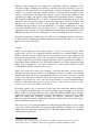
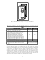
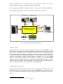
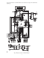
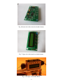
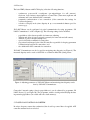
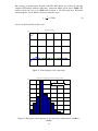
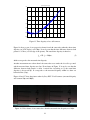
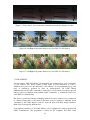
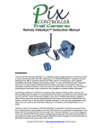
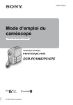
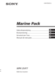
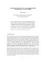
SYNCHRONISATION OF TWO CAMCORDERS WITH PI
CONTROLLER – 3D LANC MASTER
Damir Vrančić
Department of Systems and Control, J. Stefan Institute,
Jamova 39, SI-1000 Ljubljana, Slovenia
e-mail: [email protected]
Abstract: A device, which keeps two camcorders permanently in synchronisation,
has been developed. The mentioned device uses LANC (CONTROL-L) camcorder’s
inputs for synchronisation. It enables controlling of two camcorders simultaneously
via built-in buttons, by using external LANC remote controller and/or by the PC via
serial (RS232) communication. Since device requires LANC inputs on camcorders
(or still cameras), it can be used on some camcorders produced by manufacturers
Sony and Canon or some still cameras produced by Sony. Permanent
synchronisation can be achieved only on some camcorders produced by Sony. The
effectiveness of the proposed device is demonstrated by several experiments.
Keywords: stereoscopy, camcorder, PI controller, synchronization.
1. INTRODUCTION
Stereo (3D) photography is almost as old as classical photography, since the first stereoscopic
camera with two lenses was made in 1849. The first stereoscopic film was made by brothers
Lumiére in 1903. Popularity of stereoscopy had risen until the 1950s, when CinemaScope
wide-angle format won over the stereoscopic films, mainly due to reduced production costs
and higher quality. Today stereoscopic video cameras are again gaining in popularity due to
cheaper ways of producing and showing stereoscopic content. The stereoscopy is mostly used
in geodesy, medicine, chemistry and in entertainment industry. However, amateur
stereoscopic video maker is still faced with relatively high costs of stereoscopic video
equipment. One of the main requirements for making stereoscopic videos is that both
camcorders are tightly synchronised. Such synchronisation is required in order to correctly
fuse left and right pictures of the moving objects into one stereoscopic (3D) picture.
Figure 1 depicts the case when an object is moving horizontally. If the cameras are not
synchronised (right picture is taken some time interval after the left one), the right picture of
the object is taken at position b instead of a so the fused (stereoscopic) image is created in
incorrect position d instead of c. The fused stereoscopic picture therefore appears righter and
closer than in reality. The second case is when the object is moving vertically (see Figure 2).
Due to non-ideal synchronisation, the right picture is taken in position b instead of a. In this
case the stereoscopic picture cannot be fused at all. There appears double picture d instead of
one stereoscopic picture c.
1
a
b
a
b
c
c
d
d
Fig. 2. Vertical displacement due to shooting
time difference
Fig. 1. Horizontal displacement due to
shooting time difference
Accurate synchronization of camcorders (or still cameras) is therefore very important in
stereoscopy. Precise synchronisation can be achieved by using some professional video
camcorders which are equipped with connectors dedicated for synchronisation. However,
those inputs are not available in consumer video equipment, so taking quality stereoscopic
video stays out of reach for ordinary amateur videographer.
Video frames are taken from camcorder’s CCD chip about 25 (PAL) or 30 (NTSC) times per
second. The exact video frame rate depends on the frequency of camcorder’s internal
oscillator. If the first camcorder’s frame rate is f1 and the second one is f2, then time disparity
S will change over time as follows:
S=
f1 − f 2
t + S0 ,
f1
(1)
where t denotes time and S0 is initial disparity at time origin (t=0). For example, if the frame
rate of the first camcorder were f1=25.000 Hz and the frame rate of the second camcorder
were f2=25.001 Hz, the time disparity would be 2.4ms after 1 minute provided that they were
perfectly synchronised at time origin (S0=0).
Recently, some dedicated devices for synchronisation of still cameras and camcorders, like
“LANC Shepherd” [4] or “ste-fra® LANC” [2], have appeared on the market. They are using
the so-called LANC or CONTROL-L inputs on camcorders and still cameras to power-up the
cameras at the same instant. Since both camcorders should be of the same type, they become
relatively well synchronised at time origin (initial disparity S0 (1) becomes relatively small).
However, since internal oscillators in both devices are running at slightly different
frequencies, the time disparity changes over time (1), and soon becomes unacceptable.
2
Drifting of time disparity can be eliminated by modifying oscillator’s frequency of one
camcorder. Namely, changing one frequency is enough to keep time disparity S as close as
possible to 0. The question is how to modify the oscillator’s frequency? Straightforward
solution is to open the camcorder, find the oscillator’s electronic circuit and apply control
voltage to varicap diode connected to the oscillator’s crystal. Varicap diode changes its own
capacitance according to the applied voltage which results in modified oscillator’s frequency.
The additional requirement here is to have a controller which permanently keeps the time
disparity at S=0. A practical example of proposed design can be found in [7], where time
disparity was S=+-50ns. However, even though the achieved synchronisation was
remarkable, the approach has one major drawback, i.e. it requires modification of existing
camcorder’s hardware. Firstly, this can only be done by a skilled electrical engineer (with
appropriate service manual). Secondly, unauthorised modifications incur warranty loss and
additional plug has to be placed on camcorder’s body for controlling camcorder’s frame rate.
The question remained is if there exists any other way of modifying camcorder’s frame rate
by using existing standard plugs without opening a camcorder? Yes, there is a way, but it
applies only to some camcorders.
2. LANC
LANC1 (Local Application Control Bus System) is a protocol developed by Sony which
enables video devices to be controlled externally, usually from a connected LANC remote.
Remote controllers, based on LANC protocol, are frequently used by video enthusiasts and
professionals for controlling zoom, focus, record/pause commands, etc. The LANC protocol
is similar to RS232 protocol with exception that video device is permanently sending socalled LANC frames which have to be filled with command codes. Shorter explanation of the
LANC protocol, timing and codes can be found in [3]. Some specifics related to LANC
communication with still cameras is given in [8].
LANC protocol has also been used for “hacking” some Sony camcorders in order to remove
DV-input and video-input protection on some European models or to enable several hidden
functionalities. However, it is less known that LANC protocol can also be used to view and
modify some camcorder’s internal settings like white balance settings, adjustments of
brightness and contrast, etc. One of the most useful settings is oscillator adjustment. More
precisely, LANC input can be used to modify frequency of the internal oscillator on some
models of Sony camcorders2. How can it be done?
By sending specific codes to camcorder’s LANC input, basic camcorder functional settings
can be altered by modifying data bytes stored on particular pages and addresses as shown in
Figure 3. There are 16 pages (0-F) and each contains 256 addresses (00-FF) where 8-bit data
is stored. For example, modifying data on Page F and Address 1C in camcorder Sony TRV900E will change main oscillator’s frequency and therefore camcorder’s frame rate.
Particular pages and addresses which affect camcorder’s frame rate for several other Sony’s
camcorder models are given in Table 1.
The easiest way to alter camcorder functional settings through LANC input is to buy original
Sony service remote and modify data at appropriate page/address. Cheaper way is to build
simple electronic circuit and use parallel port of a PC and adequate software3 for emulating
service remote controller [6].
1
LANC is also known as Control-L.
According to author’s best knowledge, this feature is not available on still cameras produced by Sony.
3
Note that free versions of emulation software are mostly running on WIN95 and WIN98 systems.
2
3
Page=F
Page=1
00
Page=0
01
Address
Data
00
00
01
00
02
00
02
FF
FF
00
Fig. 3. Camcorder functional settings stored on pages and addresses.
Table 1 Pages and addresses of the data which affects frame rate for several Sony camcorder
models
Camcorder model
DCR-TRV900(E), VX2100(E), DCR-PC1E, DCR-PC2E,
DCR-PC3(E), DCR-PC10E, DCR-TRV9
DCR-DVD91E, DCR-DVD101(E), DCR-DVD100(E),
DCR-DVD200(E), DCR-DVD300, DCR-HC14E,
DCR-HC15(E), DCR-HC16E, DCR-HC18E,
DCR-HC20(E), DCR-HC30(E), DCR-HC85(E),
DCR-PC106E, DCR-PC107E, DCR-PC108(E),
DCR-PC330(E), DCR-PC350(E), DCR-TRV255E,
DCR-TRV260, DCR-TRV260(E), DCR-TRV360,
DCR-TRV361, DCR-TRV460(E), DCR-TRV461E
DCR-PC100E
DCR-TRV103, DCR-TRV410
DVD201(E), DVD301(E), HDR-HC1, DCR-HC40(E),
DCR-HC65, DCR-HC1000(E), DCR-IP1(E), DCRPC109(E)
Page (hex)
Address (hex)
F
1C
F
10
F
F
12
40
frame rate cannot be adjusted
Camcorder functional settings can be modified in two ways. The settings can be modified
temporary by changing data in camcorder’s volatile (RAM) or permanently by changing data
in non-volatile (e.g. E2PROM) camcorder’s memory. Temporary change of settings is
relatively safe and the change is reset after switching off the camcorder. On the contrary,
permanent change of data may stop the functioning of camcorder, since the checksum of nonvolatile memory is calculated every time after turning on the camcorder. If the calculated
checksum is different from the previously calculated checksum data, the camcorder stops
functioning. Usually, frame-rate settings are not protected by the checksum.
4
An experiment has been conducted where camcorder’s frame rate has been changed
(modifying volatile or non-volatile data at page F and address 1C) for camcorder TRV900E.
In accordance with modified data, the change of camcorder’s frame rate has been detected.
3. SPECIFICATIONS
After promising result of the previous experiment it has been decided to develop a portable
device which is able to control and maintain synchronisation of two camcorders.
The control device should comply with or have:
-
two LANC ports for connecting two camcorders or still cameras,
additional LANC port for connecting external LANC remote controller,
HMI interface (keys and LCD display) with optional external keys,
serial (RS232) connection with a PC (configuration and measurements),
time offset measurement between two LANC frames with accuracy <= 1µs,
versatile power management (internal rechargeable batteries with long autonomy and
different charging sources),
closed-loop control of time disparity (if camcorder has appropriate setting for
modifying oscillator frequency),
commands for record/pause, tele/zoom, focus near/far, camcorder’s menu operations,
etc. and
user-defined speed for tele/zoom operation and additional user-defined LANC
commands.
The block scheme of device is given in Figure 4. Since the author had previous experience
with Atmel microcontrollers, the microcontroller Atmel ATMega8 [1] has been chosen. It
offers 16kB internal program memory, 1kB static RAM, 512Bytes of E2PROM, 3 counters,
10-bit ADC converter, USART (serial communication) and several interrupt sources. The
microprocessor has been programmed by CodeVisionAVR Compiler [5], since it offers
several pre-defined functions and templates (wizards) for ATMega8.
The device has been named “3D LANC Master”.
4. 3D LANC MASTER
The electronic scheme of device is given in Fig 5. The core is microcontroller ATMega8,
which is connected to LANC ports through open-collector inverters 74LS05 and to serial port
via MAX232. The microcontroller is directly connected to 2x16 display LM016 and 4 keys
(by using pull-up and pull-down resistors). The power is taken from rechargeable batteries
and supplied by DC-to-DC converter MAX619. The electronic schemes, layouts and
programmes are given in [8]. The circuit board is shown in Figures 6 and 7 and assembled
prototype in Figure 8.
4.1 Inputs and outputs.
There are three LANC connectors in 3D LANC Master. Two are used for connecting two
camcorders (or still cameras) and one for external LANC remote controller (if desired). The
signals on LANC connector are the following: ground, power supply voltage (about 5.5V)
and LANC signal. LANC signal (either LS, RS or MS) is connected to open-collector
5
inverters (74LS054) in order to separate voltage levels (optical decouplers can be used as
well, but current consumption should be taken into consideration).
Serial communication (RS232) with PC is enabled via 9-pin serial port (DB9) and MAX232.
In-circuit (ISP) programming of the microcontroller is enabled by connector K2.
Left camcorder
Right camcorder
LANC
LANC
RS232
LANC
Microprocessor-based
closed-loop control
In-circuit
programming
Remote controller
PC
4 keys
2x16 LCD display
Fig. 4. Block scheme of 3D LANC Master.
4.2 Power supply.
3D LANC Master is powered by internal rechargeable batteries (3xAAA NiMH) in order to
reduce power consumption of connected camcorders or still cameras (the latter are usually
more sensitive to additional power consumption). The batteries can be re-charged either by
connected camcorders/still cameras, by applying external power supply (4.5-6V DC voltage)
on dedicated input or by charging the batteries in external battery charger. Charging is
controlled by switch S1A (either 3D LANC Master is switched on or off). The charging
current is controlled by a current source (transistors T1 and T2). The estimated battery
capacity is shown on LCD display. It is estimated that 3D LANC Master functions for about
10 hours with one charging. The main switch is S2A. The voltage from the batteries is
increased and stabilised to 5V by using DC-DC converter MAX619.
4.3 Human-Machine Interface.
On-board Human-Machine Interface (HMI) consists of keyboard and LCD display. The
keyboard has 4 keys, 3 are function keys and one is SHIFT/MENU key. Display consists of
two lines, each with 16 characters. Top line displays current commands associated to 3
buttons.
4
HCT05 version of the integral circuit is being currently tested.
6
Several other functions of 3D LANC Master can be achieved by using serial communication
with PC [8].
Fig. 5. Electronic circuit of “3D LANC Master”.
7
Fig. 6. Bottom side of the circuit board with elements.
Fig. 7. Upper side of the circuit board with elements.
Fig. 8. Prototype of 3D LANC Master.
8
4.4 Functions.
The basic HMI (4 buttons with LCD display) offers the following functions:
-
-
synchronous power-on/off, record/pause (pre-trigger/trigger for still cameras),
tele/zoom, focus far/near, menu functions on camcorders (enter menu, up/down and
submenu) and 2 user-defined LANC commands,
permanent synchronisation of two camcorders (if the camcorder has settings for
oscillator frequency),
selection of display mode (time disparity in µs or recommended shutter speed for
stereoscopy).
3D LANC Master can be configured via serial communication by using programme “3D
LANC Communicator” on PC computer [8]. The following settings can be modified:
-
page/address of the data responsible for frame-rate adjusting,
duration and offset of power-on signal (separately for camcorder and still camera)
duration of power-off signal during reset,
speed of tele/wide commands for camcorders,
proportional and integral gain of the PI controller responsible for keeping permanent
synchronisation between two camcorders, and
two additional LANC commands for camcorders.
3D LANC Communicator can also be used for monitoring time disparity (see Figure 9). The
measured disparity can be saved as ASCII file or as Windows Meta-File (wmf) picture.
Figure 9. Adjusting parameters of 3D LANC Master and monitoring time disparity can be
done by 3D LANC Communicator.
Camcorder’s internal settings (data in pages/addresses) can be adjusted by programme 3D
LANC Doctor [8] (see Figure 10). The programme enables viewing and modifying the data
in particular page/address (in volatile and non-volatile memory).
5. CLOSED-LOOP CONTROL ALGORITHM
In order to keep two camcorders synchronised, the closed-loop control has to be applied. A PI
controller structure has been selected:
9
t
u (t ) = K P e(t ) + ∫ K i e(τ )dτ ,
(2)
t0
where u is controller output, e is measured time disparity in µs, KP is proportional gain and Ki
is integral gain of the PI controller. Signal u represents camcorder’s data byte at particular
page/address (depends on camcorder model – see Table 1). Integration inside expression (2)
is performed only when calculated u is between 0 and 255, otherwise u is limited to either 0
or 255. The initial value of the integrator is the first measured value of data byte.
Proportional gain (KP) and integral gain (Ki) can be adjusted with programme 3D LANC
Communicator by modifying proportional factor (PF) and integral factor (IF):
1
PF
.
1.28
Ki =
IF
KP =
(3)
Figure 10. “3D LANC Doctor” can modify camcorder’s internal settings by changing data
within camcorder
6. RESULTS
When 3D LANC Master was built, it was tested on two Sony DCR-TRV900E camcorders.
First, reset impulse of length 100ms was sent to camcorders. After 20 seconds 3D LANC
Master has been switched into the closed-loop configuration (PI controller became active). PI
controller parameters were KP=0.25 (PF=4) and Ki=0.005 (IF=256). The corresponding time
disparity is shown in Figure 11 and histogram of the signal is shown in Figure 12. It can be
seen that time disparity remained within ±10µs after 200s and practically within ±5µs after
1000s.
Another experiment has been conducted on two Sony DSC-V1 still cameras. The reset
impulse of the same length (100ms) was sent to both cameras. Time disparity is shown in
Figure 13. Since the closed-loop control of time disparity is not possible, the cameras cannot
be kept in synchronisation.
10
The accuracy of measured time disparity with 3D LANC Master was verified by shooting
computer CRT monitor with two camcorders. Camcorder shutter speeds were 1/10000s. The
monitor refresh rate was set to 100Hz and resolution to 768 horizontal lines. Horizontal
refresh frequency was 81.4kHz, so electron beam takes about
tL =
1
= 12.3 µs
fV
(4)
to draw one horizontal line on the screen.
synchronisation level [µs]
200
switched into the closed−loop
150
100
50
0
−50
0
500
1000
1500
2000
2500
time [s]
Figure 11. Time disparity of two camcorders
Histogram of time disparity in time interval from t=1000s to t=2400s
400
Mean = 0.49
Standard deviation = 1.78
350
300
250
200
150
100
50
0
−4
−2
0
2
Time disparity [µs]
4
6
8
Figure 12. Histogram of time disparity of two camcorders in time interval t=1000s to
t=2400s.
11
synchronisation level [µs]
100
50
0
−50
−100
−150
−200
−250
0
100
200
300
400
500
time [s]
600
700
800
900
1000
Figure 13. Time disparity of two still cameras
Figure 14 shows a part of one progressive frame from both camcorders when the shown time
disparity (on LCD display) was 180µs. It can be seen that the time difference between both
pictures is 15 lines (see left edge of the picture). The actual time disparity is therefore:
tD = 15 ⋅ tL = 184µs ,
(5)
which corresponds to the measured time disparity.
Another measurement was taken when both camcorders were under the closed-loop control
and the measured time disparity was 2µs. From frames in Figure 15 it can be seen that the
difference between both pictures is about 1 vertical line. According to (5), the actual time
disparity is about tD=12µs. It corresponds to the measured disparity within less than one
horizontal line (12µs).
Figures 16 and 17 show the pictures taken by Sony DSC-V1 still cameras (measured disparity
was between 50µs and 100µs).
Figure 14. Video frames of two camcorders when the measured time disparity was 180µs.
12
Figure 15. Video frames of two camcorders when the measured time disparity was 2µs.
Figure 16. Left-Right-Left picture taken by two Sony DSC-V1 still cameras.
Figure 17. Left-Right-Left picture taken by two Sony DSC-V1 still cameras.
7. CONCLUSIONS
A device named “3D LANC Master” has been made for synchronisation of two camcorders
(or still cameras). The device requires LANC signal on both camcorders in order to
simultaneously power-on both camcorders (still cameras). It can permanently keep some
types of camcorders, produced by Sony, in synchronisation. 3D LANC Master
simultaneously sends LANC commands to camcorders or still cameras according to pressed
buttons, received commands from standard LANC commander, or commands received via
serial (RS232) communication.
The device is powered by internal recharging batteries in order to reduce power consumption
of connected camcorders or still cameras (the latter are more sensitive to additional power
consumption). 3D LANC Master works for about 10 hours with fully charged batteries,
which can be recharged in different ways.
Some internal parameters of 3D LANC Master can be configured by using programme 3D
LANC Communicator. The programme is written for PC computers and offers visual
13
inspection of time disparity as well. Some camcorder’s parameters can be modified (with
extreme caution!) by using programme “3D LANC Doctor”.
It was shown that 3D LANC Master worked on a pair of Sony DCR-TRV900E camcorders,
where permanent time disparity within ±10µs has been achieved. Unfortunately, permanent
synchronisation can be achieved only on some camcorders (according to Table 1)
REFERENCES
[1] Atmel. Atmel Corporation. http://www.atmel.com
[2] Bloss, W. ste-fra® LANC. http://www.digi-dat.de/produkte/index_eng.html.
[3] Boehmel M. How SONY LANCTM protocol works. http://www.boehmel.de/lanc.htm.
[4] Crockett, R. LANC Shepherd. http://www.ledametrix.com/index.html.
[5] HP InfoTech. http://www.hpinfotech.com.
[6] Kovacevic M. Enabling DV-IN on D8 & DV. http://lea.hamradio.si/~s51kq/DV-IN.HTM.
[7] Vrančić, D. (2004). Synchronizing two camcorders.
http://www-e2.ijs.si/damir.vrancic/personal/trv900/Sync/.
[8] Vrančić, D. (2005). 3D LANC Master.
http://www-e2.ijs.si/3DLANCMaster/.
14