1
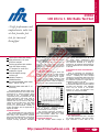
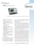
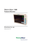
Test Equipment Solutions Datasheet
Test Equipment Solutions Ltd specialise in the second user sale, rental and distribution of
quality test & measurement (T&M) equipment. We stock all major equipment types such as
spectrum analyzers, signal generators, oscilloscopes, power meters, logic analysers etc from
all the major suppliers such as Agilent, Tektronix, Anritsu and Rohde & Schwarz.
We are focused at the professional end of the marketplace, primarily working with customers
for whom high performance, quality and service are key, whilst realising the cost savings that
second user equipment offers. As such, we fully test & refurbish equipment in our in-house,
traceable Lab. Items are supplied with manuals, accessories and typically a full no-quibble 2
year warranty. Our staff have extensive backgrounds in T&M, totalling over 150 years of
combined experience, which enables us to deliver industry-leading service and support. We
endeavour to be customer focused in every way right down to the detail, such as offering free
delivery on sales, covering the cost of warranty returns BOTH ways (plus supplying a loan
unit, if available) and supplying a free business tool with every order.
As well as the headline benefit of cost saving, second user offers shorter lead times, higher
reliability and multivendor solutions. Rental, of course, is ideal for shorter term needs and
offers fast delivery, flexibility, try-before-you-buy, zero capital expenditure, lower risk and off
balance sheet accounting. Both second user and rental improve the key business measure of
Return On Capital Employed.
We are based near Heathrow Airport in the UK from where we supply test equipment
worldwide. Our facility incorporates Sales, Support, Admin, Logistics and our own in-house
Lab.
All products supplied by Test Equipment Solutions include:
- No-quibble parts & labour warranty (we provide transport for UK mainland addresses).
- Free loan equipment during warranty repair, if available.
- Full electrical, mechanical and safety refurbishment in our in-house Lab.
- Certificate of Conformance (calibration available on request).
- Manuals and accessories required for normal operation.
- Free insured delivery to your UK mainland address (sales).
- Support from our team of seasoned Test & Measurement engineers.
- ISO9001 quality assurance.
Test equipment Solutions Ltd
Unit 8 Elder Way
Waterside Drive
Langley
Berkshire
SL3 6EP
T: +44 (0)1753 596000
F: +44 (0)1753 596001
Email: [email protected]
Web: www.TestEquipmentHQ.com
Wireless - Radio Test Sets
2965A
100 kHz to 1 GHz Radio Test Set
A high performance and
comprehensive radio test
set that provides fast
tests for increased
throughput
Fast and accurate radio testing
High performance, full span
spectrum analyzer
Tracking generator with variable
level and offset tracking
FFT analyzer for audio and
modulation signals
500 kHz digital storage
oscilloscope
Variable Frequency
SINAD/Distortion
Accurate broadband power meter
from 1 mW to 150 W
Selective power meter with 2 µV
sensitivity
The 2965A Radio Test Set builds on the
benchmark performance of its 2955 series
predecessors by offering superior speed
and ease of use. Its benefits include
competitive pricing and performance, well
proven ergonomics and broad range of
applications and options. It boasts many
features that are not found in test sets
selling for much higher prices. The design
allows high speed of operation and
accuracy of measurements, resulting in
higher throughput and the application of
tighter test limits.
Standard Features
The 2965A Radio Test Set follows the
philosophy of offering a complete package
with many of the features as standard.
Among the standard features of the 2965A
Radio Test Set are full span spectrum
analyzer, tracking generator, broadband
power meter, 500 kHz oscilloscope and a
PC compatible memory card with internal
autorun capability.
The 2965A Radio Test Set includes RF
and LF high performance spectrum
analyzers with features that are normally
only found on dedicated high performance
spectrum analyzers.
RF Spectrum Analysis
The RF spectrum analyzer allows fast
high resolution analysis of signals applied
to either of the RF inputs over a wide
dynamic range including off-air signals.
Facilities include flexible frequency level
settings, steerable markers for absolute or
relative measurement of level or frequency
and control of the resolution bandwidth.
The update rate is remarkable for this
type of product, allowing real-time
measurements on off-air signals.
The tracking generator provides a
convenient method of alignment for filters
and sub-modules whilst the offset
generator facilitates mixer testing.
LF Spectrum Analysis
The FFT analyzer allows analysis of
audio signals demodulated from RF or via
the audio input. Interference and
intermodulation products can be analyzed
and distortion observed at a range of
frequencies. An automatic sweep facility to
20 kHz complements the manual facilities
of the FFT.
Comprehensive Audio and Modulation
Sources
Three LF generators are provided for
audio stimulus along with three modulation
sources - enabling the most complex
signaling to be generated without the need
for external oscillators. These sources can
be combined to produce a single audio or
modulation source to 100 kHz.
Major signaling protocols are included
as standard to reduce the need for external
encoders and decoders. User definable
tones may be stored in non-volatile
memory so that non-standard tone
systems can easily be emulated.
Large Bright Display
The 2965A Radio Test Set is designed
for intuitive operation. The large, bright,
high resolution screen with its 22
http://www.ifrinternational.com
2695A
1
2965A
associated soft keys has significant
benefits for automated as well as manual
testing. From switch on, the 2965A Radio
Test Set welcomes the user with features
that make radio testing simple, fast and
accurate.
Selective Test Modes for Specific
Tests
The 2965A Radio Test Set allows a wide
range of radio testing.
The DUPLEX mode shows both transmit
and receive paths so that any interaction
can be observed. If one path needs closer
examination, it may be selected without
disturbing the other path.
The RF test mode is for testing
repeaters, mixers and RF systems including
SSB measurements. This mode also gives
access to the tracking generator which can
be configured to allow RF to IF and IF to RF
conversions, doubler and ÷2 analysis.
Likewise the AF Test mode provides audio
testing when the RF is not required giving
access to an audio sweep facility.
Comprehensive Cellular Testing
Testing of cellular and trunked radio is
required at many stages in the life-cycle of
a radio. For applications ranging from
factory production through to repair and
customer assurance, the test requirements
vary considerably. Simple checks through
to a full performance test of all the
important radio parameters are required.
The 2965A Radio Test Set meets all these
demands and is flexible yet easy to
operate.
The 2965A Radio Test Set provides ‘cell
site simulation’. This generates the
signaling protocol that the radio would see
from the real network. It is then possible to
place and receive calls. This activates the
receiver and transmitter, so that normal
parametric measurements can be made.
The signaling may also be verified,
permitting faults and errors to be traced
before releasing a phone on to the
network.
All system options allow ‘system
definition’ so that future changes and new
country variants can be defined by the user.
This flexibility ensures that the 2965A
Radio Test Set can develop with a rapidly
expanding market.
Built-in Automatic Tests
There are four built-in test programs,
ranging from simple call processing to
comprehensive performance testing. Each
of the tests may be run in a variety of ways
to suit individual requirements. The 2965A
Radio Test Set can offer a solution for every
application using internally run programs.
Manual Test Mode
A manual testing mode is included,
allowing tests to be repeated or varied to
identify faults.
Data Displays
Data displays show the messages being
sent to and from the radio under test.
Corrupted messages are indicated on the
display and the screen can be easily
downloaded to a printer whenever the need
arises.
2
2965A
Programming
The control capabilities and Autorun
facilities of the 2965A Radio Test Set
benefit users who are automating testing in
an attempt to reduce failures. Programs
can be written in an interpreted form of
BASIC by the user and stored inside the
instrument. Additional programs can be
downloaded via the RS-232 into the user
defined area allowing custom programs to
be run. Speed is important in all aspects of
testing particularly in automatic control.
The 2965A Radio Test Set allows multitasking for parallel measurements to be
made, further enhancing its speed.
Test Program Generation made easy
GPIB Edit and Runtime Software is a PC
based test programming and test executive
environment for developers of automatic
test applications. It runs under Windows
and allows the 2965A Radio Test Set to be
programmed using high-level language
commands. While providing simple access
to its powerful facilities the software offers
experienced designers the speed and
efficiency benefits of a high-level
programming environment. The 2965A
Radio Test Set GPIB software driver
implements all the control functions.
Commands are provided for low level
access to the 2965A Radio Test Set as well
as the main test modes and
measurements. The driver allows remote
control of transmitter and receiver testing,
off air signaling and general purpose RF
and AF testing.
Size and Weight
Not only does the 2965A Radio Test Set
pack the performance you would normally
see on a bench full of instruments, it
weighs in at under 18 kg (39.5 lb) so it is
portable when the need arises.
Results Storage
Results may be stored in a number of
ways. They may be transferred to the PC
compatible memory card or sent via the
RS-232 or parallel interface to a printer.
The memory card meets the PCMCIA 2
standard for standardization of memory
card formats.
Utilities Disk
A collection of PC software utilities is
available to aid users in programming the
2965A Radio Test Set.
A screen capture facility is available so
any screen displayed on the 2965A Radio
Test Set can be saved direct to a PC, via
the serial port, as a bit map file. These
screens can then be imported into
documents or retained on a database.
A GPIB command transfer program is
also available for use with a suitably
equipped PC – this program allows single
command transfer, file transfer into internal
memory and running of remote control
programs.
APPLICATIONS
Base Stations
Many base stations are situated with
other transmitters meaning that it is very
important to control the problems of out of
band radiation and intermodulation
products. Most are multi-channel and
operate in full duplex, which requires the
use of combiners, duplexers and filters.
The quality spectrum analyzer with tracking
generator will greatly facilitate base station
testing. The sensitivity of the receiver also
allows remote monitoring and field strength
measurements to be taken. The 2965A
Radio Test Set is light enough and small
enough to be easily carried on-site.
Antenna feeder forward and reverse
power, and VSWR measurements can be
made using the 2955 Directional Power
Head accessories which are compatible
with 2965A Radio Test Set.
The software to interface with the
Directional Power Head is supplied as
standard within the 2965A Radio Test Set.
Comprehensive
audio
waveform
generation and analysis facilities are
included for use with modems, speech
processors, filters and tone encoders.
The inclusion of a 500 kHz DSO (Digital
Storage Oscilloscope) allows audio and
demodulated signals to be analyzed,
including sequential tones. The multimeter
function completes the picture.
Production
Modern production facilities for mobile
radio equipment fall into two classes – fully
automated and fully de-skilled. In the case
of fully de-skilled processes remote control
is of primary importance. The use of IEEE488.2 commands and syntax, multitasking and high speeds make the 2965A
Radio Test Set ideal. The ease of use of the
Autorun capability, the small footprint and
the low capital outlay per work station
make it ideally suited to this application.
User calibration allows the instrument to
be
optimized
for
the
operating
environmental conditions, i.e. in an
http://www.ifrinternational.com
equipment rack or on the bench. Once run,
it will not be necessary to re-run the user
calibration unless the operating or ambient
temperature changes by more than 5°C.
Quality Assurance
With escalating exports of mobile radio
equipment around the world, the need for
acceptance testing and quality audits away
from the production environment is
increasing. It is essential in these
situations that the tests be performed with
equipment comparable to that used in
production. It is often the case, however,
that these remote centres are poorly
funded and therefore the price/
performance of the instrument is a key
issue. The 2965A Radio Test Set provides
a cost effective solution to meet these
needs.
Research and Development
The 2965A Radio Test Set with its
spectrum analyzer and high performance
signal generator is ideal for use in research
and development laboratories. The 2965A
provides a complete solution for laboratory
needs yet with flexibility to allow field
testing and fault location to be easily
achieved.
Surveillance
The needs for this market are growing.
The basic tools of this trade are a spectrum
analyzer and receiver. The 2965A Radio
Test
Set
combines
both
these
requirements.
(–17 dBm with AM)
TNC socket: –115 dBm to +13 dBm
(+3 dBm with AM)
Resolution
0.1 dB
Indication
4 digits plus sign (dBm, dBµV, µV, mV PD/EMF)
Accuracy
N-Type socket:
±1 dB up to 575 MHz,
±1.5 dB up to 1 GHz for levels above –120 dBm
±1.2 dB 575 MHz to 1 GHz over the temperature
range 15 to 35°C.
A GSM upgrade path is available for the
2965A Radio Test Set allowing effective
testing of digital GSM systems.
SSB Option
The
SSB
option
allows
the
demodulation of SSB transmissions with
CW, upper and lower sideband analysis
capabilities. The displayed frequency is
always the carrier frequency, calculated
from the mode (e.g. CW, upper SB and
lower SB) and the audio generator
frequency. Analysis capabilities include
carrier and alternate sideband suppression
to 50 dBc and audio analysis via the FFT.
Two fully variable audio generators are
available
to
perform
two
tone
measurements.
Reverse Power Protection
N-Type socket: With instrument switched on 150 W.
Overload indicated by visual and audible warning.
TNC socket: Protection up to 10 W. Reset available
on removal of RF power. Excess power indicated by
visual and audible warnings.
Output Impedance
50 Ω nominal
VSWR
N-Type socket: better than 1.2 up to 500 MHz;
better than 1.3 up to 1 GHz (typically 1.2).
TNC socket: typically 1.3 at 900 MHz.
SPECTRAL PURITY
Residual FM (CCITT weighted)
Less than 6 Hz RMS up to 575 MHz
Less than 12 Hz RMS up to 1 GHz
Residual AM (CCITT weighted)
Less than 0.05% RMS
Harmonics
Better than –30 dBc for levels up to +7 dBm (TNC)
Better than –30 dBc for levels up to –13 dBm
(N-Type)
SSB Phase Noise (20 kHz offset)
Better than –114 dBc/Hz up to 575 MHz;
Better than –108 dBc/Hz up to 1 GHz.
RF Carrier Leakage
Less than 0.5 µV PD generated at the carrier
frequency in a 50 Ω load by a 2 turn loop 25 mm or
more from the case with output level set to below
–60 dBm and terminated in a sealed 50 Ω load.
AMPLITUDE MODULATION – INTERNAL
Specification
Certain characteristics are shown as typical. These
provide additional information for use in applying the
instrument but they are unwarranted.
(Applies to version 7.00 and above)
RF Signal Generator
FREQUENCY
Range
100 kHz to 1 GHz, useable 90 kHz to 1.15 GHz
Resolution
1 Hz
Indication
10 digit display
The data display mode allows the
sequence of signaling on both the forward
and reverse channels to be viewed on the
same screen.
Carrier On/Off
Keyboard operation, reduces signal generator output
to less than –120 dBm
Spurious Signals
Better than –45 dBc for carrier frequencies from
100 kHz to 36 MHz;
Better than –50 dBc for carrier frequencies above
36 MHz
Military
The capabilities of the 2965A Radio Test
Set allow a wide range of military AM, FM
and SSB radio equipment to be tested,
including systems using tone signaling.
High power handling capability (up to
150 W) saves the need for external power
attenuators when testing vehicle radios.
Analog Cellular
2965A Radio Test Set has optional
software for major analog systems which
retain the ease of use and comprehensive
test capability of the 2960 series.
Wireless - Radio Test Sets
2965A
Setting
Keyboard entry, delta increment/decrement function
and rotary variable control
Accuracy
As frequency standard
OUTPUT LEVEL
Range
One-port Dx:
N-Type socket: –135 dBm to –40 dBm
TNC socket: –115 dBm to –20 dBm
Rx Test and two port Dx modes:
N-Type socket: –135 dBm to –7 dBm
Frequency Range
100 kHz to 400 MHz, useable to 1.15 GHz
AM Depth Range
0 to 99%
Resolution
0.1%
Indication
3 digits
Setting
Keyboard entry, delta increment/decrement function
and rotary variable control
Accuracy(1) (up to 85% AM)
±4% of setting ±1 digit for modulation frequency
1 kHz
±6% of setting ±1 digit for modulation frequencies
from 30 Hz to 10 kHz
±8% of setting ±1 digit for modulation frequencies
from 10 kHz to 20 kHz
Distortion
Less than 1% at 1 kHz for modulation depths up to
30%, CCITT weighted
Less than 2% for modulation frequencies from
100 Hz to 20 kHz and depths up to 85%
Modulation Frequency
Range: 20 Hz to 15 kHz for carrier frequencies up to
36 MHz; 20 Hz to 20 kHz for carrier frequencies up
to 400 MHz.
Resolution: 0.1 Hz below 10 kHz; 1 Hz below
20 kHz.
http://www.ifrinternational.com
2965A
3
2965A
AMPLITUDE MODULATION – EXTERNAL
Indication
4 digits
Input impedance
Nominally 1 MΩ in parallel with 100 pF
Setting
Keyboard entry, delta increment/decrement function
and rotary variable control
Frequency Range
As internal AM
Accuracy
±5% ±1 digit for modulation frequencies from
250 Hz to 3.4 kHz, over the range 15 to 35°C
(0.1% per °C outside this range)
Modulation Frequency Range
As internal AM with AC or DC coupling
Accuracy
As internal ±2%
Distortion (1)
Less than 1% for modulation frequencies from
250 Hz to 5 kHz (for deviation 1 rad to 160 rads)
Input Sensitivity
1 V RMS for indicated modulation depth
FREQUENCY MODULATION – INTERNAL
Frequency Range
100 kHz to 1 GHz, useable 90 kHz to 1.15 GHz
Maximum Deviation
Modulation Frequency
Range: 250 Hz to 5 kHz
Resolution
0.1 Hz
PHASE MODULATION – EXTERNAL
Input Impedance
Nominally 1 MΩ in parallel with 100 pF
Frequency Range
As internal phase modulation
Modulation Frequency Range
250 Hz to 5 kHz
Input Sensitivity
2.828 V pk-pk for indicated deviation
Accuracy
As internal ±2%
Indication
4 digits
Setting
Keyboard entry, delta increment/decrement function
and rotary variable control.
Accuracy(1)
±3% ±1 digit at 1 kHz over the range 15 to 35°C
(0.1% per °C outside this range)
Typically ±3% ±1 digit for modulation frequencies
from 20 Hz to 5 kHz
Typically ±7% ±1 digit for modulation frequencies
from 5 kHz to 20 kHz
Typically ±10% ±1 digit for modulation frequencies
from 20 kHz to 75 kHz
Distortion(1)
Less than 0.5% for modulation frequencies from
250 Hz to 5 kHz (for deviation 1 kHz to 800 kHz).
Less than 1% for modulation frequencies from
50 Hz to 20 kHz (for deviation 1 kHz to 800 kHz).
Modulation Frequency Range(6)
20 Hz to 20 kHz Mod generators 1, 2, 3 or
20 Hz to 100 kHz Mod generator 4
Resolution
0.1 Hz
FREQUENCY MODULATION – EXTERNAL
Input Impedance
Nominally 1 MΩ in parallel with 100 pF
Frequency Range
As internal FM
Modulation Frequency Range
DC to 100 kHz (DC coupled)
10 Hz to 100 kHz (AC coupled)
Input Sensitivity
2.828 V pk-pk for indicated deviation
Accuracy
As internal ±2% for frequencies up to 20 kHz
PHASE MODULATION – INTERNAL
Frequency Range
100 kHz to 1 GHz, useable to 1.15 GHz
Maximum Deviation
INTERNAL MODULATION AND AUDIO SOURCES
Up to 6 tone sources can be assigned as 3
modulation generators and 3 audio tone generators
Modulation Modes
Internal generators may be assigned to AM, FM, ΦM
Audio Voltmeter
Input Impedance
Nominally 1 MΩ in parallel with 100 pF
Accuracy (bandpass filter selected)
±0.5 dB ± resolution
Sensitivity
100 mV for 46 dB SINAD
Audio Distortion Meter
Frequency
1 kHz default. User selectable up to 20 kHz
Distortion Range
0 to 100%
Resolution
0.1% distortion for readings greater than 1%
0.2% distortion for readings less than 1%
Indication
3 digits and barchart with peak hold.
Accuracy
±5% of reading ± resolution (Bandpass filter
selected)
Sensitivity
100 mV for 0.5% distortion
Audio S/N Meter
S/N Range
0 to 100 dB
Resolution
0.1 dB for readings less than 50 dB
0.2 dB for readings less than 70 dB
Indication
3 digits and barchart with peak hold
Accuracy
±0.5 dB ± resolution
Sensitivity
2 V for 60 dB, 200 mV for 40 dB
Level Ranges
0 to 10, 0 to 30, 0 to 100, 0 to 300 mV, 0 to 1,
0 to 3, 0 to 10, 0 to 30 V RMS reading
(autoranging or fixed)
Operating Modes
Single or Repetitive sweep
Level Indication
4 digits and barchart with peak hold
Level Accuracy (DC Coupled)(3) (5)
±2% of reading ±1 mV ± resolution, DC and 100 Hz
to 20 kHz
±4% of reading ±1 mV ± resolution, 40 Hz to
100 kHz
Level Accuracy (AC Coupled)(3)
±2% of reading ±1 mV, ± resolution 150 Hz to
20 kHz
±4% of reading ±1 mV, ± resolution 100 Hz to
100 kHz
Residual Noise
100 µV RMS CCITT weighted
Audio Frequency Meter
Range
10 Hz to 500 kHz
Resolution
0.1 Hz from 10 Hz to 5 kHz
1 Hz from 5 kHz to 50 kHz
10 Hz from 50 kHz to 500 kHz
Indication
6 digits
Sensitivity
On barchart greater than 25% FSD (DC coupled)
Audio SINAD Meter
Frequency
1 kHz default. User selectable up to 20 kHz
SINAD Range
5 to 50 dB
2965A
Indication
3 digits and barchart with peak hold
Frequency Range
DC and 20 Hz to 500 kHz
AC only 20 Hz to 500 kHz
Polarized DC less than 10 Hz
Accuracy
As frequency standard ±1 digit ± resolution
4
Resolution
0.1 dB for readings less than 20 dB
0.2 dB for readings less than 25 dB
Audio Oscilloscope
Frequency Range
DC to 500 kHz
10 Hz to 500 kHz (AC coupled)
Glitch Catching
1 µs minimum
Voltage Ranges
2 mV/div to 20 V/div in a 1, 2, 5 sequence
Voltage Accuracy
±5% of full scale
Timebase
5 µs/div to 10 s/div in a 1, 2, 5 sequence
Timebase Accuracy
As frequency standard
Trigger Mode
Auto trigger
Marker Indication
Level: M1-M2, M2-M1
Time: M1-M2, M2-M1
Graticule
10 Horizontal by 8 Vertical divisions
Can be magnified to full screen
Audio FFT Analyzer
Span Widths
50 Hz to 50 kHz in a 5, 10, 25 sequence.
Above 40 kHz signals are attenuated by
80 dB/octave
Graticule
10 Horizontal by 8 Vertical divisions
Can be magnified to full screen
Level Reference (top of screen)
10 mV to 20 V, in a 1, 2, 5 sequence
Level Accuracy
±0.3 dB 100 Hz to 15 kHz; typically ±1 dB 40 Hz
to 40 kHz
http://www.ifrinternational.com
Vertical Scaling
1, 2, 5, 10 dB/div
RF Frequency Meter
Dynamic Range
60 dB
Range
100 kHz to 1 GHz
Max Hold Facility
Resolution
1 Hz or 10 Hz selectable
Audio Sweep facility
DC to 20 kHz
Indication
Up to 10 digits
Marker Indication
Level: M1, M2, M1-M2
Frequency: M1, M2, M1-M2
Accuracy
As Frequency Standard ±2 Hz ± resolution
Audio Barcharts
Displays: AF voltage, SINAD, Distortion, S/N.
Vertical Resolution: 1% of full scale
Ranging: Autoranging, range hold or manual
selection (up/down), 1, 3, 10 sequence with
hysteresis
With peak hold facility
Audio and Modulation Filters
300 Hz Lowpass (±0.1 dB less than 150 Hz,
±0.2 dB, 150-200 Hz relative to 100 Hz).
300 Hz to 3.4 kHz Bandpass (±0.4 dB, 400 to
2100 Hz relative to 1 kHz).
5 kHz Lowpass (±0.3 dB at <3 kHz relative to
1 kHz)
20 kHz Lowpass ±0.3 dB at <12 kHz, typically
–0.9 dB at <15 kHz and –3 dB at 20 kHz relative to
1 kHz
CCITT Psophometric
C-MESSAGE
See also under Environmental/User Calibration
Multimeter
Input Terminals
3 x 4 mm, ‘Volt/Ohm’, ‘Current’ and ‘Common’
Maximum Input Voltage
375 V with respect to instrument chassis
Dynamic Range (Auto tuned)
As RF Power Meter (broadband)
Frequency Range (Auto tuned)
10 MHz to 999.9 MHz
Sensitivity
Manual tuned: –100 dBm (TNC) dependent on
receiver bandwidth in off air test mode
Offset Frequency Range
±1 MHz dependent on receiver bandwidth
RF Power Meter (Broadband)
Frequency Range
100 kHz to 1 GHz
Dynamic Range (Auto tuned)
10 mW to 150 W (N-Type), 100 µW to 0.5 W (TNC)
Power Reading
True mean power
Indication Units
Watts
Resolution
Better than 1%
Indication
3 digits and barchart with peak hold
RF Spectrum Analyzer
Frequency
Range: 100 kHz to 1 GHz, useable from 30 kHz to
1.05 GHz
Spans
500 Hz/div to 100 MHz/div, in a 1, 2, 5 sequence
Resolution Bandwidth
300 Hz to 300 kHz in a 1, 3, 10 sequence and
3 MHz (automatically selected according to span
and manually selectable).
Video bandwidth – fixed at 3 kHz
Filter Shape
Nominally 3 dB/60 dB, 1:11 (300 Hz to 30 kHz
bandwidth)
Reference Level (top of screen)
–100 dBm to +70 dBm
On Screen Dynamic Range
80 dB
Vertical Resolution
0.5 dB on 10 dB/div, 0.05 dB on 1 dB/div
Level Accuracy (5)
Typically ±2.5 dB
See also under Environmental/User Calibration
Intermodulation Distortion
Less than 80 dB for 2 signals on screen at
reference level
Sweep Speeds
Optimum sweep speed selected according to span
and resolution bandwidth
Modes
Single sweep and continuous
Graticule
10 horizontal by 8 vertical divisions
Expanded Mode
Can be made to occupy full screen for high
definition
Resolution
0.1% of FSD
Accuracy(5)
100 kHz to 500 MHz:
±7.5% (0.3 dB), 0.1 W to 50 W (N-Type).
±10% (0.4 dB), 20 mW to 150 W (N-Type).
±12% (0.5 dB), 200 µW to 50 mW (TNC).
500 MHz to 1 GHz:
±12% (0.5 dB), 20 mW to 150 W (N-Type).
±15% (0.6 dB), 200 µW to 50 mW (TNC).
100 kHz to 1 GHz:
±7.5% (0.3 dB), 0.1 W to 50 W (N-Type) +10%
(0.4 dB).
1 mW to 50 mW (TNC) for ambient temperatures in
the range 15 to 35°C.
See also under Environmental/User Calibration
Accuracy (5)
±3% of reading ±1 mV ±1 digit
See also under Environmental/User Calibration
Maximum Safe Continuous Rating
N-Type: 50 W
TNC: 0.5 W; overload protected to 10 W
Level Range
–135 dBm to +13 dBm
Indication
4 digits and barchart with peak hold
Intermittent Rating
N-Type: 150 W for limited periods, typically two
minutes at 20°C. Typical off to on ratio is 6:1.
Overload indicated by audible and visual warning
VOLTMETER
Voltage Range
0 to 300 V, 0 to 30 V, 0 to 3 V, 0 to 300 mV,
Terminals, ‘Volt/Ohm’ and ‘Common’, maximum
crest factor 3:1 at range full scale
Frequency Range
Polarized DC or 40 Hz to 1 kHz
Input Impedance
Nominally 6 MΩ in parallel with 100 pF
AMMETER
Current Range
0 to 1 A and 0 to 10 A
RF Power Meter (Selective)
Frequency Range
Polarized DC or 40 Hz to 1 kHz
Frequency Range
100 kHz to 1 GHz
Resolution
1 mA below 1 A; 10 mA below 10 A
IF Bandwidth
300 Hz to 30 kHz in a 1, 3, 10 sequence and
110 kHz, 280 kHz and 3 MHz
Accuracy
±5% of reading ±1 mA ±1 digit
Dynamic Range (Manual tuned)
0 dBm to +50 dBm (110 kHz IF bandwidth)
(N-Type
–90 dBm to +20 dBm (110 kHz IF bandwidth)
(TNC)
Indication
4 digits and barchart with peak hold
RESISTANCE METER
Power Reading
Average
Resistance Ranges
100 Ω, 1 kΩ, 10 kΩ, 100 kΩ, 1 MΩ
Indication Units
dBm
Resolution
1 Ω below 1 kΩ or 3 digits
Accuracy (5)
±5% of reading ±1 Ω ±1 digit
Continuity Test continuous tone if reading is less
than 10 Ω
Indication
4 digits and bar chart with peak hold
Resolution
0.1 dB
Indication
3 digits + barchart with peak hold
Accuracy (5)
Typically ±2.5 dB N-Type & TNC
See also under Environmental/User Calibration
Wireless - Radio Test Sets
2965A
Markers
M1 and M2
Indication
Level: M1, M2, M1-M2
Frequency: M1, M2, M1-M2
TRACKING GENERATOR
Available in RF TEST mode
Frequency Range
100 kHz to 1 GHz
Offset Tracking
Allows testing of mixers, IFs, fundamental and 2nd
harmonic analysis (up, down, x2, ÷2)
Modulation Analyzer
Dynamic Range (Auto tuned)
As RF Power Meter (Broadband)
Sensitivity (Manual tuned)
N-Type –30 dBm (110 kHz IF bandwidth)
TNC –50 dBm (110 kHz IF bandwidth)
TNC (off-air test mode) –101 dBm (2 µV 10 dB
SINAD in 30 kHz IF bandwidth and CCITT weighting)
Demodulation
Accuracy maintained on signals greater than
–60 dBm
Receiver Bandwidths
300 Hz to 30 kHz in a 1, 3, 10 sequence and
110 kHz, 280 kHz and 3 MHz
Demodulation Filters
As audio analyzer plus 5 kHz lowpass (+0.3 dB at
less than 3.4 kHz relative to 1 kHz)
Audio Output
Available in to an internal loudspeaker, demodulated
output or accessory socket for external loudspeaker
or headphones.
Switching Speed
Nominally less than 1 ms channel to channel up to
50 MHz apart, settling to within 1 kHz of final
frequency
Demodulated Output
Nominal output impedance less than 10 Ω. Output
http://www.ifrinternational.com
2965A
5
2965A
voltage is range dependent (2 V peak at top of range).
Range
0.1 mV to 5 V RMS (maximum AF output 7 V peak,
all generators combined)
AMPLITUDE MODULATION
Setting
Keyboard entry, delta increment/decrement function
and rotary control
Frequency Range
100 kHz to 1 GHz
Accuracy
±3% ±1 digit, 250 Hz to 5 kHz
±5% ±1 digit, 10 Hz to 20 kHz
±10% ±1 digit, 20 kHz to 75 kHz
Resolution
0.1% AM
Indication
3 digits and barchart with peak hold
Accuracy (up to 85% AM)(1) (5)
±% of reading, ±1% AM, 250 Hz to 5 kHz.
Typically ±5% of reading, ±1% AM, 50 Hz to 15 kHz.
Demodulation Distortion(1)
Less than 1% at 1 kHz, CCITT weighted
Output Impedance
Nominally 5 Ω
Protection
Maximum applied voltage 50 V
SIGNAL PURITY
Distortion(2)
Less than 0.5% at 1 kHz measured in a 30 kHz
bandwidth
Less than 1% from 20 Hz to 20 kHz measured in an
80 kHz bandwidth
Typically 0.1% for levels greater than 100 mV
Residual AM
Less than 0.1% AM, CCITT weighted
FREQUENCY MODULATION
Frequency Range
1 MHz to 1 GHz
Residual Noise
Less than 50 µV RMS (CCITT weighted)
Modulation Frequency Range
20 Hz to 20 kHz
DC Offset
Less than 10 mV
Deviation Range
0 to 100 kHz
Signaling Encoder/Decoder
Resolution
10 Hz below 10 kHz deviation; 100 Hz below
100 kHz deviation
Indication
3 digits and barchart with peak hold
Accuracy (1) (3) (5)
±3% ± resolution for modulation frequency of 1 kHz
±5% ± resolution for modulation frequencies from
100 Hz to 15 kHz
Demodulation Distortion(1)
Less than 0.5% at 1 kHz, CCITT weighted
Residual FM
Less than 25 Hz RMS CCITT weighted
Sequential tones functions
Encodes and decodes up to 40 tones.
CCIR, ZVEI, DZVEI, EEA, EIA or user defined.
Any of the tones may be extended.
Continuous, burst and single step modes available.
User defined tones
Up to three frequency plans may be defined and
stored within the 2965 for sequential tones.
Any of the standard tone frequency plans may be
copied to user defined and modified.
Tone length 10 ms to 1 s.
Extended tone length 100 ms to 10 s.
CTCSS tones mode
Standard tone frequencies may be selected from a
menu
PHASE MODULATION
Frequency Range
1 MHz to 1 GHz
Modulation Frequency Range
250 Hz to 5 kHz
DTMF Encoder/Decode
Generation and decode of DTMF tones, displaying
Hi/Lo frequencies, frequency error, timing information
and twist.
Deviation Range
0 to 20 rads
DCS Encode/Decode
Generation and decoding of digitally coded squelch
Resolution
0.01 rads
POCSAG generator
Generation of POCSAG code CCIR No.1
Rec 584. Bit rates from 400 to 9600 bit/s
Indication
3 digits and barchart with peak hold
Audio Monitor
Audio and demodulation signals and audio signals
may be monitored via the internal loudspeaker or via
the accessory socket output or BNC socket on the
rear panel
Accuracy (1) (3) (5)
±5% ± resolution
Demodulation Distortion(1)
Less than 0.5% at 1 kHz, CCITT weighted
SSB Option
Audio Generators
See section on modulation generators for interaction
of audio and modulation generators.
FREQUENCY
Range(6)
1 Hz to 20 kHz AF Gens 1, 2 & 3 or
1 Hz to 100 kHz AF Gen 4
Setting
Keyboard entry, delta increment/decrement function
and rotary control
Indication
6 digits
Resolution
0.1 Hz
Accuracy
As frequency standard
2965A
– as RF Gen (AM mode)
– to 0.1 Hz resolution
– as SINAD meter
– as Distortion meter
in SSB option
General Features
Keyboard and Display
Logical color coded keyboard with bright high
resolution CRT
Resolution
0.1 mV
AM Depth Range
0 to 99.9%
SSB Rx
Sideband Generator
Offset measurement
SINAD
Distortion
Note: No audio is available
INTERFACES
Indication
4 digits
Modulation Frequency Range
20 Hz to 20 kHz
6
LEVEL
Squelch
A manual squelch control is provided with a variable
threshold
SSB Tx
Frequency, Range and
meter accuracy
Power, level and
meter accuracy
Detection Range
AF Demod range
Demod distortion
Carrier and Alternate
s/band suppression
Sideband/CW Analyzer
Spectrum Analyzer
Audio Generator
Sideband Selection
– as RF frequency
– as Broadband power
– 100 µV to 150 W
– 10 Hz to 5 kHz
– <2% @ 1 kHz, CCITT
weighted
– Better than –50 dBc
– max 5 kHz full span
frequency range
– as RF spectrum
analyzer
– two – as audio
generator
– LSB, USB, CW
GPIB
Full control of all major instrument functions via the
GPIB interface
Flexibility is further enhanced by IFR’s
implementation of IEEE-488.2.
Capability
Complies with the following subsets as defined in
IEEE-488.1-1978:- SH1, AH1, T5, TE0, L4, LE0,
SR1, RL1, PP0, DC1, DT1, C1, E1.
Serial
Serial interface is provided for connection of RS-232
for instrument remote control. 9 Way socket. Control
language is based on IEEE P1174.
Parallel Printer
Connector 25 way female D-Type. Provision made
for graphics screen dump. A selection of printer
drivers are included.
Accessory Socket
Allows the connection of various optional
accessories.
With suitable adapters is compatible with most
2955 series accessories.
Memory Card
Meets PCMCIA2/JEIDA – 4 standard. The memory
card facility allows the storage of results and set
ups.
Video Output
Color, compatible with most VGA monitors.
15 way Sub Miniature D Type.
Frequency Standard
Internal Frequency Standard Output
Frequency
10 MHz
Level
Nominally 2 V pk-pk
Output Impedance
Nominally 50 Ω
Temperature Stability
Better than 5 in 108, 5 to 50°C
Ageing Rate
Better than 1 in 107 per year, after 1 month
continuous use
Warm Up Time
Less than 10 minutes to within 2 in 107 at 20°C
External Frequency Standard Input
Frequencies
1, 2, 5 and 10 MHz
Level
From 1 V pk-pk to 5 V pk-pk
Input Impedance
Nominally 1 MΩ in parallel with 40 pF
Power Requirements
AC supply
Voltage
88 V to 132 V and 188 V to 265 V
Supply frequency
45 Hz to 65 Hz
Power
Nominally 135 W, 260 W maximum, for future
options
http://www.ifrinternational.com
Electromagnetic Compatibility
Conforms with the protection requirements of
Council directive 89/336/EEC.
Complies with the limits specified in the following
standards:
EN55011 Class B
CISPR11
EN50082-1
IEC 801-2, 3, 4
EN60555-2
IEC 555-2
Safety
Complies with IEC 1010-1, BS EN61010-1 for class
1 portable equipment and is for use in a pollution
degree 2 environment. The instrument is designed
to operate from an installation category 1 or 2
supply.
Environmental
Rated Range Of Use
0 to 50°C and up to 95% relative humidity at 40°C.
User Calibration
User calibrations are provided to maintain high
accuracy for any ambient temperature (e.g. in ATE
racks or in field measurements). Having allowed the
instrument to stabilize, running the user calibrations
optimizes the performance at that temperature.
A change in temperature of 5°C from the calibration
temperature affects readings as below. These figures
are provided as a guide to typical performance.
Typical variations are as follows for a 5°C change in
temperature.
Power Meter:
Broadband
2%
Selective
0.5 dB
Spectrum Analyzer Level
0.5 dB
Audio Analyzer & Modulation Filters
Audio Voltage
0.4%
Demod depth & deviation 0.4%
Multimeter:
Voltage
0.5%
Current
0.5%
STORAGE AND TRANSPORT
Parametric Auto Test Routines
AF Frequency
AF Level
FM Deviation
Mod Frequency
Rx Distortion
Rx Expansion
Rx Sensitivity
Rx SINAD
Rx S/N
Tx Compression
Tx Distortion
Tx Frequency
Tx Level
Tx Power Level
Tx Limiting
Tx Mod Level
Tx Noise
Tx SINAD
Tx S/N
SAT Deviation
SAT Frequency
ST Duration
ST Frequency
ST Deviation
Data Deviation
DSAT Deviation
Signaling Auto Test Routines
Registration/Roaming Update
Place Call
Clear From Mobile
Page Mobile
Handoff
Clear From Land
Hook Flash
DTMF Decode
Data Performance
PTT On
PTT Off
Auto Test Pause Modes
Pause Manual Only
Pause On Failure
Pause Always
DIMENSIONS AND WEIGHT
Excluding handle, feet and covers.
Height
Width
Depth
177 mm
370 mm
540 mm
(6.9 in)
(14.5 in)
(21.2 in)
Including handle, feet and covers.
Height
Width
Depth
203 mm
(7.9 in)
420 mm
(16.5 in)
600 mm
(23.6 in)
Temperature
–40 to +70°C
Weight
Less than 18 kg (39.5 lb)
Altitude
Up to 2500 m (pressurized freight at 27 kPa
differential)
NOTES
(1) At low modulation levels the residual AM/FM
may become significant.
(2) At low audio levels the residual noise may
become significant.
(3) Audio and Modulation filter passband errors not
included.
(4) Typical performance figures are non-warranted.
(5) Refer to USER CALIBRATION section.
(6) Either 3 modulation plus 3 audio generators up
to 20 kHz or 1 modulation or 1 audio generator
to 100 kHz.
Internal Test Software
OPTION 10 NMT CELLULAR SOFTWARE
NMT450
NMT900
Benelux
NMTF
Austria
Spain
Malaysia
Indonesia
Saudi 1
Saudi 2
Thailand
Oman
Tunisia
Hungary
Poland
Russia
Czech
Bulgaria
Slovenia
Turkey
USER DEFINED NMT
OPTION 11 AMPS CELLULAR SOFTWARE
E-AMPS
N-AMPS
USER DEFINED AMPS
OPTION 12 TACS CELLULAR SOFTWARE
E-TACS
TACS-2
C-TACS I
C-TACS II
J-TACS
N-TACS
USER DEFINED TACS
OPTION 13 MPT1327
Band III
UK Water
Autonet
Madeira
NZ MPT1327
USER DEFINED MPT
TRUNKING SOFTWARE
JRC
Hong Kong
AMT
NL-TRAXYS
PH-INDO
Versions and Accessories
When ordering please quote full ordering number
information
Ordering
numbers
2965A
Versions
Radio Test Set
Options
Option 01
French Language Version
Option 02
Spanish Language Version
Option 03
German Language Version
Option 09
SSB receiver option
Option 10
NMT Cellular Radio option*
Option 11
AMPS Cellular Radio option
(including N-AMPS)*
Option 12
TACS Cellular Radio option
(including N-TACS)*
Option 13
MPT 1327/MPT 1343 Trunked
Radio option*
Option 14
PMRTEST for FM
* Specify which analog cellular option (options 10 to 14) is
required at time of ordering
Contact your local sales outlet for details of availability
of options
Option 21
GSM Hardware and Software Upgrade,
P-GSM, E-GSM, User Defined GSM
Supplied with
AC Supply lead
Operating Manual
Multimeter Lead Kit (Two 4 mm leads to
test points)
Accessories
54421/001
BNC Telescopic antenna
54431/023
20 dB AF attenuator (BNC)
54112/158
Hard Transit Case
54112/157
Soft Carrying Case
54127/310
Rack Mounting Kit
59000/189
Memory Card (128 k)
54411/052
Impedance Matching Unit
(requires 46884/645 Accessory socket
adapter)
46884/645
Accessory socket adapter (for use with
2955 accessories)
46884/646
Accessory Socket ‘Y’ adapter
46884/560
Parallel Printer Interface Cable
46884/649
Serial port to PC Cable 25 way
46884/650
Serial port to PC Cable 9 way
43129/189
GPIB Cable
43130/596
Coaxial cable N-Type(m) to TNC(m)
(double screened)
54311/095
Coaxial cable N-Type(m) to N-Type(m)
(1 metre)
54311/071
TNC(m) to BNC(f) adapter
54311/092
N-Type(m) to BNC(f) adapter
52388/900
1 GHz Active Probe
54441/012
Power supply for probe 52388/900
B27033
GPIB Edit and Runtime Software,
Single User, Dongled.
B27071
2965A Radio Test Set GPIB Software Driver
46880/056
Service manual
Option 21
GSM Hardware and Software Upgrade
Note that this option is only available as a
retrospective upgrade. To order a complete
Radio Test Set, with GSM capability, see
2966A.
Service Support
W2
Two year warranty
W3
Three year warranty
Contact your local sales outlet for availability of these
and other service plans
Wireless - Radio Test Sets
2965A
OPTION 14 PMRTEST SOFTWARE
USER DEFINED PMR for FM radios
General Features (Systems)
Test Modes
Auto Test/Manual Test
Auto Test Programs
Call Processing Only
Call and RF Testing
Brief Testing
Comprehensive Testing
User Defined Test
http://www.ifrinternational.com
2965A
7
2965A
IFR Americas, Inc., 10200 West York Street, Wichita, Kansas
67215-8999, USA. E-mail: [email protected]
Tel: +1 316 522 4981 Toll Free USA: 1 800 835 2352 Fax: +1 316 522 1360
IFR Ltd, Longacres House, Norton Green Road, Stevenage, Herts
SG1 2BA, United Kingdom. E-mail: [email protected]
Tel: +44 (0) 1438 742200 Freephone UK: 0800 282 388 Fax: +44 (0) 1438 727601
As we are always seeking to improve our products, the information in this document gives only a general indication of the product capacity, performance and suitability, none of which shall form part of any
contract. We reserve the right to make design changes without notice. All trademarks are acknowledged. Parent Company IFR Systems, Inc. © IFR Ltd. 1999.
8
2965A
http://www.ifrinternational.com
Part no. 46891-017
Issue 1