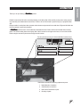
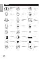
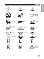
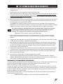
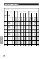
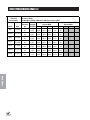
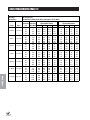
1
Spray Star 1000
with Manual 3-Way Valve
SN: 100413
December 2008
CONTENTS
Introduction
Introduction ................................................................................. 1-9
Introduction .................................................................................. 1
Symbols ................................................................................... 2-3
Safe Practices ............................................................................. 4
Safe Spraying Practices .............................................................. 5
Operation
Specifications .............................................................................. 6
Optional Equipment ..................................................................... 6
Setup .......................................................................................... 7
Controls & Instruments ............................................................. 8-9
Operation .................................................................................. 10-14
Schematics
Spraying Procedure ................................................................. 15-21
Spraying Introduction ................................................................. 15
Turf Management ....................................................................... 15
Hose & Handgun Spraying ......................................................... 16
Nozzles ................................................................................ 16-17
Spraying Procedures
Calibration Introduction .............................................................. 18
The Nozzle Chart Method ..................................................... 19-20
The “128” Methood ................................................................ 20-21
Nozzle Charts ............................................................................ 22-27
Nozzle Performance Chart #1 .................................................... 22
Nozzle Performance Chart #2 .................................................... 23
Nozzle Charts
Nozzle Performance Chart #3 .................................................... 24
Nozzle Performance Chart #4 .................................................... 25
Nozzle Performance Chart #5 .................................................... 26
Nozzle Performance Chart #6 .................................................... 27
Reference .................................................................................. 28-29
Abbreviations and Conversions .................................................. 28
Reference
Declaration of Conformity ........................................................... 29
Warranty ........................................................... Inside Back Cover
Thank you for purchasing a Smithco product.
Read this manual and all other manuals pertaining to the Spray Star 1000 carefully as they have safety, operating, assembly and maintenance instructions. Failure to do so could result in personal injury or equipment damage.
Keep manuals in a safe place after operator and maintenance personnel have read them. Right and left sides are
from the operator’s seat, facing forward.
All Smithco machines have a Serial Number and Model Number. Both numbers are needed when ordering
parts. The serial number plate on the Spray Star 1000 is located on the right main frame, in front of the oil tank.
Refer to engine manual for placement of engine serial number.
For easy access record your Serial and Model numbers here.
Information needed when ordering replacement parts:
1. Model Number of machine.
2. Serial Number of machine.
3. Name and Part Number of part.
4. Quantity of parts.
1
Introduction
INTRODUCTION
Introduction
SYMBOLS
2
Read Operator’s
Manual
Electrical Power
No Electrical
Power
Engine - Stop
Engine - Start
Engine - Run
Engine Oil
Temperature
Light
Water
Temperature
RPM
Gasoline
Diesel
Glow Plug - On
Glow Plug - Off
Glow Plug
Hour Meter
Hour Meter
Hand Throttle
Choke - Closed
Choke - Open
Park Brake
Park Brake
Release
Hydraulic Oil
Level
Fuse
H
R
Up/Down Arrow
Down/Lower
Up/Raise
No Smoking
Moving Parts
Manual
Operation
Pinch Point
Step
Hot Surface
Hydraulic Fluid
Penetration
Lift Arm
Tractor
Engage
Disengage
PTO
Ground Speed
Fast
Slow
High
Reverse
L
N
Low
Neutral
F
Introduction
SYMBOLS
Forward
Warning
Danger
Caution
3
SAFE PRACTICES
Introduction
1. It is your responsibility to read this manual and all publications associated with this machine.
2. Never allow anyone to operate or service the machine or its optional equipment without proper training and
instructions. Never allow minors to operate any equipment.
3. Learn the proper use of the machine, the location and purpose of all the controls and gauges before you
operate the equipment. Working with unfamiliar equipment can lead to accidents.
4. Wear all the necessary protective clothing and personal safety devises to protect your head, eyes, ears,
hands and feet. Operate the machine only in daylight or in good artificial light.
5. Inspect the area where the equipment will be used. Pick up all debris you can find before operating.
Beware of overhead obstructions and underground obstacles. Stay alert for hidden hazards.
6. Never operate equipment that is not in perfect working order or without decals, guards, shields, or other
protective devices in place.
7. Never disconnect or bypass any switch.
8. Carbon monoxide in the exhaust fumes can be fatal when inhaled, never operate a machine without proper
ventilation.
9. Fuel is highly flammable, handle with care.
10. Keep engine clean. Allow the engine to cool before storing and always remove the ignition key.
11. Disengage all drives and set park brake before starting the engine.
12. Never use your hands to search for oil leaks. Hydraulic fluid under pressure can penetrate the skin and
cause serious injury.
13. This machine demands your attention. To prevent loss of control or tipping of the vehicle:
A. Use extra caution in backing up the vehicle. Ensure area is clear.
B. Do not stop or start suddenly on any slope.
C. Reduce speed on slopes and in sharp turns. Use caution when changing directions on slopes.
D. Stay alert for holes in the terrain and other hidden hazards.
14. Before leaving operator’s position:
A. Disengage all drives.
B. Set park brake.
C. Shut engine off and remove the ignition key.
D. If engine has to run to perform any maintenance keep hands, feet, clothing and all other parts of body
away from moving parts.
15. Keep hands, feet and clothing away from moving parts. Wait for all movement to stop before you clean,
adjust or service the machine.
16. Keep the area of operation clear of all bystanders.
17. Never carry passengers.
18. Stop engine before making repairs/adjustments or checking/adding oil to the crankcase.
19. Use parts and materials supplied by Smithco only. Do not modify any function or part.
20. Use caution when booms are down as they extend out beyond the center line of the machine.
21. The tank is a confined space, take precaution.
These machines are intended for professional maintenance on golf courses, sports turf, and any other
area maintained turf and related trails, paths and lots. No guarantee as to the suitability for any task is
expressed or implied.
4
Persons engaged in the handling, preparation or application of chemicals must follow accepted practices to
insure the safety of themselves and others,
1. WEAR protective clothing including: gloves, hat, respirator, eye protection and skin covering suitable for
protection from chemicals being used.
2. BATHE thoroughly after any exposure to chemicals, giving particular attention to eyes, nose, ears and
mouth.
3. CLEAN equipment and materials in accordance with employer, municipal and state regulations. Use only
approved areas and drains.
4. DISPOSE of chemicals and rinse solutions by approved and legal means.
5. PROVIDE methods and materials for operators to wash eyes and hands immediately during the spraying
process.
6. PROVIDE methods and materials for control, safe dilution and neutralization of chemical spills during
preparation, spraying, transporting and cleanup.
7. Always check and follow the directions and safety warnings of the chemicals to be used.
8. Secure the discharge lines before starting the pump. An unsecured discharge line may whip.
9. Periodically inspect the pump and the system components.
10. Check hoses for weak or worn condition before each use. Make certain that all connections are tight and
secure.
11. Do not operate unit with leaks, frayed, kinked hoses or tubing. Repair or replace immediately.
12. Use only pipe, hose and fittings rated for maximum pressure or pressure at which pressure relief valve is
set at. When replacing pipe, hose or fittings, use new product.
13. Do not operate a gasoline engine in an enclosed area. Be sure the area is well ventilated.
14. Do not use these pumps for pumping water or other liquids for human or animal consumption.
15.
Do not pump flammable or explosive fluids such as gasoline, fuel oil, kerosene, etc.
Do not use in explosive atmospheres. The pump should be used only with liquids
compatible with the pump component materials.
16. Be sure all exposed moving parts are guarded and that all coupling devices are securely attached before
applying power.
17. Before servicing, disconnect all power, make sure all pressure in the system is relieved, drain all liquids
from the system and flush.
18. Protect pump from freezing conditions by draining liquid and pumping rust inhibiting antifreeze solution
through the system, coating the pump interior.
5
Introduction
SAFE SPRAYING PRACTICES
SPECIFICATIONS
Introduction
WEIGHTS AND DIMENSIONS
Length
Width
Width With Boom Open
Height
Wheel Base
Weight Empty
Weight Full
112" (285 cm)
70" (178 cm)
180" (457 cm)
48" (122 cm)
53" (135 cm)
1200 lbs (544 kg)
2200 lbs (998 kg)
SOUND LEVEL (DB)
At ear level
At 3 ft (0.914 m)
At 30 ft (9.14 m)
88 dB
84 dB
72 dB
ENGINE
Make
Model#
Type / Spec#
Horsepower
Fuel
Cooling System
Lubrication System
Alternator
Kohler
Command CH25S
PA 68673
25 hp (18 kW)
Unleaded 87 Octane Gasoline Minimum
Air Cooled
Full Pressure
25 amp
WHEELS & TIRE
Front: Two 20 x 10.00 x 10 NHS Multi-Rib; 20 psi (1.4 bar)
Rear: Two 24 x 12.00 x 12 NHS Multi-Trac; 20 psi (1.4 bar)
SPEED
Forward Speed
Reverse Speed
0-8 m.p.h. (0-12.8 kph)
0-3 m.p.h. (0-4.8 kph)
BATTERY
BCI Group
Cold Cranking Amps
Ground Terminal Polarity
Maximum Length
Maximum Width
Maximum Height
Automotive type 24F - 12 volt
Size 24
575 minimum
Negative (-)
10.25" (26 cm)
6.88" (17 cm)
10" (25 cm)
FLUID CAPACITY
Crankcase Oil
Fuel
Hydraulic Fluid
Grade of Hydraulic Fluid
See Engine Manual
7 gallon (26.5 liters)
5 gallon (19 liters)
SAE 10W-40 API Service SJ or higher Motor Oil
OPTIONAL EQUIPMENT
10-417
10-419
10-103
10-160
10-301
10-365
10-377
16-129
16-906
6
Chemical Cleanload Safe Fill System
1002 203 Spray System
Fresh Water Tank
1008 440 Spray System
Electric Actuator Lift Kit
1010 3-Way Manual System
15' Stainless Steel Boom - manual
10-378 Foam Marker
15' Terrain Following Boom
15-622 Weather Canopy
Water Meter KIt (gallons)
10-370 Water Meter Kit (liters)
Hose Reel Mounting Kit
33-541 Triple Nozzle Kit for 15ft/5m 9 nozzle Boom
Manual Rewind Hose Reel, 200-foot/61-meter capacity
Electric Rewind Hose Reel, 200-foot/61-meter capacity
The Spray Star 1000 arrives from Smithco setup and ready for service. Depending on freight conditions the
battery may have to be installed.
The spray system is normally shipped attached to the 1000 Prime Mover. If a spray system is to be fitted to a
Prime Mover by a dealer or end user, assemble and attach the components in accordance with the parts drawings in the Spray Star 1000 Parts/Service Manual.
1. Check the tire pressure. The front and rear tires are 20 psi
(1.4 bar).
2. Battery is located under the seat. This is a negative grounding system.
Connecting battery cables to the wrong post could
result in personal injury and/or damage to the
electrical system. Make sure battery and cables do
not interfere or rub on any moving part. Connect
red positive (+) cable (A) to battery first. When
disconnecting remove black negative (-) cable (B)
first.
3. Check hydraulic fluid level in tank located on the left side of
the seat. Remove cap and add SAE 10W-40 API Service SJ or higher motor oil if necessary. Fluid level
should be about 2-21/2" (5-6.4 cm) from the top of the tank when cold. DO NOT OVERFILL.
4. Fill fuel tank, located on the right side, with Unleaded 87 Octane gasoline (minimum).
Fuel is flammable, caution must be used when storing or handling it. Do not fill fuel tank
while engine is running or an enclosed area, fumes are explosive and dangerous to inhale.
DO NOT SMOKE while filling the fuel tank. DO NOT OVERFILL.
5. Machine should be greased before starting, refer to Spray Star 1000 Parts/Service Manual for location.
6. Attach the Spray Boom and any other Optional Equipment to the Prime Mover, in accordance with
instructions in the Spray Star 1000 Parts/Service Manual. The nozzles must be the correct distance above
the turf as described in Turf Spraying Guide. The spray boom must operate properly and the outer sections must break away safely if an object is struck by them, they must then return to normal operation
position.
7. Be sure to double check boom heights, nozzle spacing and displacement before spraying.
8. Machine is shipped with windshield washer fluid in Spray System to prevent freezing. Flush system
completely with clear water. Fill tank with water and retighten the four bolts used to hold the tank in place.
9. Read operating instructions before starting.
Never allow pump to run dry! The valve on the suction side of the pump (between the pump
and tank) must be fully open whenever the pump is operated.
7
Introduction
SETUP
CONTROLS $ INSTRUCMENTS
Introduction
A. Hour Meter - The hour meter indicates hours of machine operation. It operates only when the ignition
switch is on.
B.
Speedometer - The Speedometer indicates ground speed of the vehicle in miles per hour and kilometers
per hour.
C. Oil Light - The oil light should come on when the ignition is on without the engine running and go out when
the engine is running. The oil light will light when the oil pressure is low. If oil light should come on, shut
engine off immediately and find the cause.
D. Ignition Switch - The ignition switch has three positions: Off - Run - Start.
E. Tilt Steering - Hold lever down and adjust steering wheel to desired position and release lever.
F. Buzzer - The buzzer sounds if the pump is running dry.
G. Lights - This rocker switch turns lights on by pushing on the top and off by pushing on the bottom.
H. Spray Pump - This rocker switch turns the spray pump on by pushing on the top and off by pushing on the
bottom.
I. Left Boom Switch - This rocker switch lifts and lowers the left
boom.
J. Right Boom Switch - This rocker switch lifts and lowers the right
boom.
K. Choke - The choke is used in starting the engine. Pull choke out to
close choke plate when starting a cold engine. Push in when
engine starts. A warm engine may not require "choking" to start.
L. Hand Throttle - The hand throttle is used to regulate engine speed.
M. Park Brake - The park brake is only a parking brake. Pull back to
release, push forward to apply. Some adjustment can be made by
turning the knob clockwise to tighten and counter clockwise to
loosen.
8
Introduction
CONTROLS & INSTRUMENTS
N. Spray Boss Control - Engages and disengages speed boss. Forward
is engage and all the way back is disengage. When the lever is
engaged it sets a stop for the accelerator. The accelerator pedal must
be used to maintain this speed. To adjust speed use the knob on the
end of the lever, counter clockwise increases speed and clockwise
decreases speed. Disengage the lever and you will have full accelerator pedal range.
O. Cup Holder - Holds standard cup.
P. Master Boom Switch - is used to override the master switch on the
computer console of the spray systems.
Q. Reverse Pedal - This pedal controls ground speed in the reverse
direction.
R.
Accelerator Pedal - This pedal controls ground speed. Press pedal to
increase speed. Varying the amount of movement of the pedal will
vary the ground speed.
MASTER BOOM SWITCH
The master boom switch (P), located on the left floorboard is used to override the master switch on the computer
console of the spray systems. By pushing down it will turn on/off the booms. For the Raven 440 System the
Master Switch on the computer must be off for the master boom control switch to work.
9
OPERATION
Before operating the Spray Star 1000, become familiar with all controls and functions. Also complete all maintenance requirements and read all safety warnings. Knowing the Spray Star 1000 thoroughly, how it operates, and
by doing the prescribed maintenance steps, you can expect trouble free operation for years to come.
SAFETY
Safety needs to always be the concern of an operator of a moving vehicle or any machine with moving parts.
1. Keep all shields and guards in place.
Operation
2. Keep the parking brake engaged any time the operator is away from the vehicle or whenever service is
performed.
3. Always wear the necessary protective clothing and equipment.
4. Turn engine off when refueling or performing maintenance not specifically requiring engine power.
DAILY CHECKLIST
1. Check the engine oil level. Add as needed. DO NOT OVERFILL. Refer to engine owner's manual for oil
grade and procedure.
2. Tire pressure should be 20 psi (1.4 bar) maximum.
3. Inspect the electrical system and battery cables for loose connections or frayed wiring. Replace any faulty
equipment or tighten if loose.
4. Check hardware for loose or missing nuts, bolts, screws, etc., and tighten or replace as needed.
5. Inspect hydraulic lines for damage or leaks. Never use hands to inspect for leaks.
6. Check the hydraulic fluid level. The hydraulic fluid tank is located on the left side of the machine. The fluid
level should be 2"-2½" (5 - 6.4 cm) from the top of the tank when cold. Use only SAE 10W-40 API Service
SJ or higher Motor Oil.
7. Inspect the steering, throttle and shift linkages for good hookups and
clear travel.
8. Check controls for smooth, proper working operation. Lubricate as
needed.
9. Check park brake adjustments. Adjust as required.
10. Check anti-vibration mounts on engine frame.
STARTING THE ENGINE
1. Make sure the fuel flow valve is ‘On’. It is located on the fuel tank.
2. The ignition switch is located on the dashboard. Insert the key (A) and
turn clockwise until the engine starts (C). Release the key and it will return to the run position (B). Use the choke and hand throttle as necessary.
3. Allow engine to idle and warm up before selecting direction of travel.
STOPPING THE ENGINE
If the engine has been running under high power, let it run at slow idle speed a few minutes
to cool the engine down, before turning the ignition switch to the OFF position.
1. Disengage spray pump.
2. Move the throttle lever to “slow” and turn ignition key to the “off” position.
3. Remove the ignition key and engage the park brake.
Never leave the vehicle unattended with the engine running. Always bring the vehicle to a
complete stop, engage park brake, turn key off and remove key.
10
OPERATION
Before using the Spray Star, the operator and spray technician must familiarize themselves with all of the information on
chemical spraying contained in the Turf Spray Guide.
TOWING UNIT
When it is necessary to move the Spray Star 1000 without the engine running, the bypass valve built into hydrostatic
pump must be "open" by turning it counterclockwise. The valve is located on the bottom of the pump. An "open" valve
allows fluid to pass through the wheels freely. When normal driven operation is desired, valve should be "closed" by
turning it clockwise. Failure to "close" the valve with engine running means no power to wheels.
HILLSIDE OPERATION
Do NOT stop or start suddenly on any slope. Be especially cautious when changing direction. Do NOT operate on
slopes greater than 20°.
BATTERY
Batteries normally produce explosive gases which can cause personal injury. Do not allow flames, sparks or any ignited object to come near the battery. When charging or working near battery, always shield your eyes and always provide proper ventilation.
Battery cable should be disconnected before using “Fast Charge”.
Charge battery at 15 amps for 10 minutes or 7 amps for 30 minutes. Do not exceed the recommended charging rate. If
electrolyte starts boiling over, decrease charging.
Always remove grounded (-) battery clamp first and replace it last. Avoid hazards by:
1.
Filling batteries in well-ventilated areas.
2.
Wear eye protection and rubber gloves.
3.
Avoid breathing fumes when electrolyte is added.
4.
Avoid spilling or dripping electrolyte.
Battery Electrolyte is an acidic solution and should be handled with care. If electrolyte is splashed on
any part of your body, flush all contact areas immediately with liberal amounts of water. Get medical
attention immediately.
JUMP STARTING
Use of booster battery and jumper cables. Particular care should be used when connecting a booster
battery. Use proper polarity in order to prevent sparks.
To jump start (negative grounded battery):
1.
Shield eyes.
2.
Connect ends of one cable to positive (+) terminals of each battery, first (A) then (B).
3.
Connect one end of other cable to negative (-) terminal of
"good" battery (C).
4.
Connect other end of cable (D) to engine block on unit being
started (NOT to negative (-) terminal of battery)
To prevent damage to other electrical components on unit being
started, make certain that engine is at idle speed before disconnecting jumper cables.
11
Operation
All testing and calibrating of sprayers is to be done with water, not chemicals. This insures the safety
to all involved in performing the calibration operation. Only after all calibration procedures are completed should chemical be added to the sprayer.
OPERATION
SPRAY TANK AGITATION
The gate valve on the suction side of the pump, between the tank and the pump must be open before pump is
engaged. Close this valve only when necessary to clean the filter with spray material in the spray tank.
Front View
Back View
Operation
A. Main Pressure Adjustment - Turn to adjust desired pressure on the pressure gauge.
B. Main Boom Lever - Allows pressure to enter the system. Down is engage, up is disengage.
C. Pressure Gauge - indicates in PSI when spraying.
D. Boom Levers - Three levers that turn on each boom section, right - center - left.
E. Boom Pressure Adjustment - Three adjustment knobs that adjust the pressure for each boom. They
match the boom lever that is above them. To raise pressure close knob. To lower pressure open knob.
SPRAYER VALVE SETTING
1. Engage the main boom lever (B) to allow pressure into the system.
2. Flip all boom levers (D) up to engage.
3. Adjust the main pressure (A) to show desired pressure on pressure gauge (C).
4. Doing one boom section at a time, Push the first boom lever (D) down or shut off. If pressure gauge drops
in psi close the boom pressure knob (E) below boom lever. If pressure rises open boom pressure knob.
Objective is to have equalized pressure when the boom lever is flipped. Do this with all three boom levers.
5. When pressure is equalized an all three booms the valve has been configured for spraying.
12
OPERATION
If your Spray Star is fitted with a hose reel, there is a third ball valve on the discharge system to supply material
to the hose reel.
Nozzle
Diameter
1
/8"
/8"
1
/8"
5
/32"
5
/32"
5
/32"
3
/16"
3
/16"
3
/16"
1
Input to
Agitator
in gpm
Input to
Agitator
in L/min
1.9
2.7
3.8
2.8
4.2
5.5
3.6
5.6
7.9
7.2
10.2
14.4
10.6
15.9
20.8
13.6
21.2
29.9
Agitator Agitator
Pressure Pressure
in psi
in bar
25
50
100
25
50
100
25
50
100
1.7
3.4
6.9
1.7
3.4
6.9
1.7
33.4
6.9
Agitator
Output
in gpm
Agitator
Output
in L/min
6.3
10.0
15.0
7.6
12.2
17.5
9.1
14.3
18.7
23.8
37.9
56.8
28.8
46.2
66.2
34.4
54.1
70.8
Operation
The Quadrajet agitation system operates with four venturi jets in the tank bottom. These jets have replaceable
orifice discs which discharge the following amounts of spay material.
You can change orifice disc sizes to enhance spray system performance. Smaller discs reduce amount of agitation (desirable in some foaming materials) and make more dischargeable liquid available for nozzles. Larger (or
none) discs increase amount of agitation and make less dischargeable liquid available for nozzles.
SPRAY OPERATION (After Proper Setup and Calibration)
1. Add 1/2 the amount of water required for the spray operation to tank using air gap filler.
2. Start engine, set engine speed below 2000 RPM, and engage pump after taking all previously described
safety and operation precautions.
3. Open agitator valve.
4. Add chemicals (taking all precautions described in this manual and by the chemical manufacturer).
a. Liquids may be poured directly into tank.
b. Wettable powder chemicals must be pre-mixed with water in a container to form a slurry. The mixture
is then added to the tank through the fillwell strainer.
c. Chemical in soluble packs are place into the fillwell strainer basket and dissolved by adding water
through the basket.
The balance of the water required for the spray operation is added to the tank through the fillwell strainer,
using the air gap filler. This will wash any undissolved chemical into the tank.
5. Transport to sprayer site with and agitator operating.
6. Set Engine speed between 2000-3200 RPM.
7. (Optional) Engage ground speed control.
8. Obtain desired spraying speed before activating spray with switches on spray control console.
Review the capacity of nozzles being used. Total capacity of all nozzles plus agitation
system must not exceed pumping system capabilities refer to Spraying Procedure section of
this manual. FLUSH PUMP AFTER USE
Shut-Off 20GPM 40GPM 60GPM 80GPM 100GPM
120psi 100psi 80psi
60psi
30psi
10psi
100psi 95psi
76psi
52psi
26psi
5psi
80psi
75psi
62psi
45psi
21psi
60psi
55psi
40psi
25psi
5psi
To determine the correct performance data for your application, first shut off all flow on discharge side of pump and
detemine the shut-off pressure at the pump. Use this Shut-Off pressure to determine which line of data applies.
13
SPRAY OPERATION
One of the most common causes for faulty-pump performance is corrosion inside the pump. Flush the pump and
entire system with a solution that will chemically neutralize the liquid pumped. Mix according to manufacturer’s
directions. This will dissolve most residue remaining in the pump, leaving the inside of the pump clean for the
next use.
Operation
TO PREVENT CORROSION
After cleaning the pump as directed, flush it with a permanent type automobile antifreeze (Prestone, Zerex, etc.)
containing a rust inhibitor. Use a 50% solution that is, half antifreeze and half water. Then coat the interior of the
pump with a substance which will prevent corrosion such as Fluid Film or WD40. If unit will not be used for an
extended period of time, disconnect hoses into and out of the pump, seal openings to the pump with caps or
tape. Dispose of fluids according to all federal, state and local regulations.
All chemicals and chemical residue must be removed after each use. Dispose of fluids and
residue according to all federal, state and local regulations.
SPRAYER CLEANING
Empty tank and clean unit thoroughly after each use following these instructions:
1. Remove coupling and rinse inside of tank thoroughly with clean water, replace coupling.
2. Fill tank ten percent full with clean water, start pump and discharge water through spray hose or spray
boom (with nozzles removed), until empty.
3. Remove drain coupling again and rinse tank interior thoroughly.
4. Rinse exterior of sprayer thoroughly with clean water.
MANUAL HOSE REEL
Located at the back of the Spray Star behind the tank. Open the ball valve located near the pump to allow fluid to
flow into the hose reel. Place the lockout pin in the unlocked position by pulling and turning it half a turn, this will
allow you to pull out additional hose or to use the handle and wind up the hose. To prevent movement during
transport or storage place the lockout pin in the locked position.
ELECTRIC HOSE REEL
Located at the back of the Spray Star behind the tank. Open the ball valve located near the pump to allow fluid to
flow into the hose reel. To unwind hose just pull on the hose to get the desired amount. To wind up the hose
make sure the toggle switch is in the ON position, push the momentary push button switch until you have reeled
in the amount of hose desire. Turn off the safety switch when not in use.
FOAM MARKER
The control box is located to the right of the control panel. Use lever on compressor to designate which boom is
to be used to dispense foam. Use dial located on the foamer to adjust pressure for the amount of foam that will
be dispensed. Switch on compressor also turns foamer on or off.
14
SPRAYING INTRODUCTION
This section is intended to offer practical guidelines for the distribution of liquid chemicals over an area of
turfgrass such as golf courses, park land, school grounds and lawns.Smithco makes no representation as to
the suitability of any technique or product for any particular situation. This section is suitable for self-propelled
spray vehicles or sprayers mounted onto vehicles.
Boom Spraying is the most effective, accurate and efficient method of applying chemicals to large turf areas. It
may be done by means of:
• A dedicated spray vehicle
• A sprayer mounted upon a utility vehicle
Sprayers are typically equipped with wide spray booms. Generally these booms are between 15 feet (4.5 m) and
20 feet (6 m) in width. They are divided into three sections, with hinges that permit the long outer sections to
automatically move out of the way and reset if an obstacle such as a tree or fence is in you path.
To minimize the chance for missed areas or double application use a device to mark the outside boundaries of
each spray swath. Foam markers and dye markers are advisable.
TURF MANAGEMENT
Turf management chemicals are made for four general purposes:
1. Fungicides: Prevent or cure fungus on turfgrass. They are made in 2 general types:
2. Insecticides: Eliminate damaging insects and worms (such as grubs, beetles, ants, etc.)
3. Herbicides: Control and eliminate undesirable weeds and grass from turf areas and non-turf areas such
as bunkers, trails, fences, etc.
4. Nutrients & Fertilizer: Promote growth, beauty and color in turfgrass.
Some materials have to be applied so that they get into the soil below the plant leaves, This is called "soil application". In order to do this, they are best applied with a large volume of water. They are often then watered-in
using the irrigation system. This type of chemical material includes systemic chemicals and chemicals designed to destroy pests which live in the thatch and the soil.
Other materials must be applied to reach a problem that is present on the plant leaves. This is called “Foliar
Application” and requires a lower volume of water. Instead of irrigation water, these materials are further activated
by dry air and sunshine. They include contact fungicide and many herbicides.
The user of sprayers and chemicals must follow the directions provided with the spray material. It is the only
way to insure safe and effective results. It provides information on how much chemical and how much water is to
be applied to the area to be sprayed.
Though there are many types and sizes of nozzles, two specific types have proven most successful in turfgrass
management.
• The first type is target-directed. It sprays material in a direct line downwards to the target turfgrass.
These are flat fan nozzles, commonly referred to as TeeJet nozzles. They are available in a wide variety of
sizes for any required discharge volume rate. They are the best for many contact or foliar applied pesticides. They are spaced either 10" (25 cm) or 20" (51 cm) apart and overlap one another by about 1/3.
• The second type useful in turf management are broadcast type nozzles. They are commonly referred to
as turfjet or floodjet nozzles. They spray a hollow-cone shaped pattern of much larger droplets which fall
quickly to the turf under their own weight. They are best for systemic pesticides or any material requiring a
large volume of water for soil application. The larger droplets are not as subject to drift from wind and are a
safer, more environmentally friendly choice in many situations.
15
Spraying Procedures
• Systemic - Chemicals enter the plant system and protect or cure it of, fungus.
• Contact - Kills fungus with which it comes into contact.
HOSE & HANDGUN SPRAYING
A handgun (hand-nozzle or hand-lance) is used to control and direct the spray pattern to the ground, shrub or
tree. They must be constructed of long lasting and noncorrosive materials such as brass, stainless or aluminum.
The handgun fits to a hose of any length from the sprayer allowing operator mobility. The hose should be as
short as possible while still permitting operator mobility.
Liquid looses pressure due to friction as it travels through the hose, 1-3 psi (0.07-0.21 bar) for each foot (30 cm)
of hose. For most operations 1/2" (1.25 cm) inside diameter hose is adequate. Trees over 40 ft (12 m) high require 3/4" (2 cm) inside diameter hose and a sprayer pump capable of delivering a volume of at least 20 gpm (75
lpm) and a pressure of at least 400 psi (28 bar).
NOZZLES
Always be alert to the possibility of a plugged or damaged nozzles. Serious misapplications may result. Check
nozzle output periodically.
Modern nozzles use spring and diaphragm check valves to insure positive cutoff of chemicals without drip.
Snap-on caps make replacing and cleaning nozzles, quick, easy and fool proof with proper reinstallation.
An operator can see at a glance if all nozzles are the same size by the color code.
3 FUNCTIONS FOR A SPRAY BOOM NOZZLE
1. Regulating the flow is done through size of the orifice (opening) within the nozzle. All nozzles, regardless
of type, have some point within them that regulates the flow of liquid. Obviously, the larger the opening the
greater the rate of flow volume. Volume is expressed in Gallons Per Minute (gpm) or Liters Per Minute
(lpm). Do not confuse the term volume with application rate, which will be covered later.
Spraying Procedures
As pressure increases, the flow volume in a given nozzle also increases. For example, an average size
nozzle which discharges 0.52 gpm (1.4 lpm) at 30 psi (2 bar), will discharge 0.73 gpm (2 lpm) at 60 psi (4
bar). In this example, an increase in pressure of 100% has caused an increase in discharge of 40%.
Some nozzles deliver a small volume (for example: 0.2 gpm (0.75 lpm)). Some nozzles deliver a relatively
large volume (for example: 1.5 gpm (5.7 lpm)), or 71/2 times as much as the smaller nozzle in this example.
The amount of material (volume) to be applied is determined by the effect the chemical has on the turf.
2. The nozzle on a sprayer is to form the liquid into droplets. The size of the droplet is determined by two
factors design and system pressure (psi/bar).
Particular applications are done best by big droplets such as systemic fungicides, insecticides and some
herbicides in order to reduce drift. Other applications require small droplets like contact fungicides and
some herbicides. Again, this is determined by whether the chemical is foliar applied or soil applied. Large
droplets for soil applied material, small droplets for foliar applied materials that evenly cover the plant
better.
Pressure also affects droplet size. More pressure at the same nozzle produces smaller droplets, more
subject to drift. The general rule on pressure is to use the lowest pressure possible with just enough to
form adequate spray nozzle patterns.
16
NOZZLES
(CONTINUED)
3. Disperse the material in a specific pattern that will insure even distribution of chemical across the swath
covered by the boom.
As shown (to the right) the pattern formed by flat
fan (TeeJet) nozzles would show most liquid
concentrated at the center, then tapering off where
it begins to overlap with the next nozzle-approximately 1/3. The pattern of liquid dispersed by the
hollow-cone is more even across its width. Each
nozzle overlaps the adjoining nozzle by 100%.
That is to say the area covered by each nozzle
extends to the center of the two nozzles on either
side.
In order to properly develop their spray pattern, each nozzle must be the proper distance from the next
nozzle (spacing) and the proper height above the ground.
NOZZLE SCREENS (STRAINERS)
Smaller nozzles require nozzle screens or strainers to prevent clogging.
• Teejet type nozzles size 11001 and 110015 require 100 mesh screens.
• Teejet type nozzles from size 11002 through 11008 require 50 mesh screens.
• Turbo TurfJet Nozzles Size 1/4 TTJ02-VS and larger do not require strainers.
• Turbo Floodjet Nozzles TF-VS2 through TF-VS3 require 50 mesh screens.
SPACING
Turf spray nozzles are normally 20" (51 cm) apart. Some cases 40" (101 cm), depending on the type of spray
boom and type of area to be sprayed.
Very fine, level areas (golf greens and tees, bowling lawns, tennis courts, etc.) may be sprayed with nozzles
spaced every 10" (25 cm).
BOOM HEIGHT
Height is very important in permitting spray nozzles to develop their proper spray pattern. If nozzles are too high,
excessive overlap develops. If nozzles are too low, there is not enough overlapping of nozzle spray patterns.
NOZZLE
TYPE
80° Flat Fan
65° Flat Fan
Turbo TurfJet
Turbo TurfJet
Turbo Floodjet
Turbo Floodjet
NOZZLE
SPACING
20" (51 cm)
20" (51 cm)
20" (51 cm)
40" (101 cm)
20" (51 cm)
40" (100 cm)
HEIGHT ABOVE
THE GROUND
18" (45 cm)
12" (30 cm)
15" (38 cm)
19" (48 cm)
16" (41 cm)
18" (45 cm)
Improper nozzle height or spacing prevents proper application of chemical. Some areas are under treated and
chemicals are ineffective. Some areas are overtreated with wasted chemical and possible turf damage.
Operating your sprayer at a desired speed and pressure on a hard, dry surface is a good method of checking
spraying consistency. Observe nozzles in operation, observe if the area dries evenly. If there are alternating wet
and dry streaks, raise or lower the spray boom. If the wet streaks are directly under the nozzle, the boom is too
low. If the wet streaks are between the nozzles, the boom is too high.
17
Spraying Procedures
• Turbo Floodjet Nozzles TF-VS4 and larger do not require screens.
CALIBRATION INTRODUCTION
Calibrating simply means to adjust a set of variables on the sprayer in order to deliver the desired amount of
chemical to a known area of turf.
The job of calibrating the sprayer consists of balancing these variables so that your sprayer delivers the desired
application rate. That is, an amount of chemical on a given area. It is expressed as:
Gallons Per Acre (gpa) (1 US gpa = 0.83 UK gpa)
or Gallons Per 1,000 Square Feet (gpt)
or Liters Per Hectare (lph) (1 US gpa = 9.35 lph)
A number of acceptable methods for calibrating a turf sprayer are widely available. The calibration method chosen must take these variables into account. They must include known ground speed (by measurement or from
an accurate speedometer) and nozzle output (gpm or lpm) from a nozzle chart or from actual measurement. The
variables are:
PRESSURE
Just as pressure increases the volume discharge rate, it also increases the application rate. Pressure must
increase by 4 times in order to double the application rate. Small pressure changes of 10 psi (1.4 bar) or less do
not greatly affect performance.
Pressure is established and maintained by a pressure control valve or by a flow control valve located on the
sprayer.
NOZZLE CAPACITY (VOLUME)
We have covered the different types of spray patterns of various nozzles and made our selection of type accordingly. We now have to choose a size which will provide the correct application rate.
Spraying Procedures
Sizes are available for all requirements. Consult the nozzle chart in this manual for your nozzle type in order to
select the correct size.
TRAVEL SPEED
Increased travel speed decreases the application rate (gpa, gpt or lph). Travel speed must be safe and appropriate for the area to be sprayed.
Unlike pressure changes which have only a minor effect on application rate, ground speed changes have a more
major and direct effect. For example: 50% decrease in ground speed means a 100% increase in application
rate. If the vehicle does not have an accurate speedometer, correct speed must be determined by timing the
sprayer travel over a measured distance. (Refer to the page in this manual titled, “Abbreviations and Conversions”.
To calibrate a sprayer, the user must:
1. Understand the Variables
2. Set those variables using one of the proven methods available.
3. Make a trial run and measure the output (use water, not chemical).
4. Determine the output.
5. Make adjustments to the 3 variables until the output is at the desired level.
This covers the principles of what must be known to prepare a sprayer for operation.
There are other acceptable and proven methods of calibrating a turf sprayer for application.
Other techniques may be more suitable depending on operational needs and technical
competence of the operator.
18
THE NOZZLE CHART METHOD OF CALIBRATION
The Nozzle Chart Method is useful when the sprayer nozzles are new or nearly new. It is also the most useful
method to employ when the sprayer is equipped with an Electronic Spray Control System. The Electronic Spray
Control System does most of the calibration work, it is up to the operator to select the proper combination of
nozzle size and ground speed which will deliver the desired application rate.
The nozzle chart method requires the use of the appropriate nozzle charts which are found in the back of this
manual (Nozzle Charts 1 through 8). Nozzle charts for other nozzles are available from the manufacturer.
CALIBRATION STEPS
1. Determine “HOW” your sprayer is to be calibrated from the list of variables below.
a. Nozzle Type (Teejet, Turbo Turf, Turbo Flood)
b. Spacing (10" (25 cm) or 20" (51 cm) or 30" (76 cm))
c. Expression of Application Rate (gpa or gpt or lph)
The answers to these three questions will direct you to the appropriate nozzle chart for your application.
The correct nozzle chart MUST be used.
2. Determine the Desired Application Rate.
This is determined from the information on chemical labels or other technical information available from a
variety of sources.
Conditions over which the sprayer will operate generally dictate the appropriate ground speed. Within the
limits of practicality and efficiency, spraying should generally be done at lowest possible speed. This
increases operator safety and contributes to more precise application of chemicals. For example, golf
greens and tees and hill areas would generally be sprayed in the range of 21/2 to 31/2 mph (4-6 kph).
Larger, open and more level areas such as golf fairways and park or school grounds would be sprayed at
41/2 to 6 mph (7-10 kph).
The vehicle which carries or tows the sprayer should be equipped with a precise low-speed speedometer.
If it is not, exact ground speed at a given engine speed must be determined by timing the travel of the
sprayer over a measured distance.
4. Determine Nozzle Size.
Refer to the appropriate nozzle chart in the back of this manual for your nozzle TYPE (the type of nozzle
you have or type you wish to use), nozzle SPACING and CALIBRATION TYPE (gpm, gpt or lph).
You will note from the chart, that application rates from any given nozzle decrease as the ground speed
increases. In other words, the faster you drive, the less material you are applying.
Application rates are shown in the columns to the right of the charts. Once the desired application rate is
decided upon, it should be located, as nearly as possible in one of these columns on the appropriate chart
for your operation. It could well be that the approximate rate desired would be obtained from the nozzles
already installed in the boom. If this is not possible, then nozzles will need to be changed.
When selecting a new nozzle size refer to the “Discharge Rate Column” on the nozzle
charts. The Discharge Rate (gpm or lpm) multiplied by the number of nozzles should not
exceed 75% of the actual discharge volume of the sprayer pump. [i.e., if you need to use
nozzles which discharge 0.8 gpm (3.0 lpm), and the spray boom is equipped with 12 nozzles,
the sprayer pump would have to produce an actual discharge volume of 13 gpm (49 lpm) in
order to properly supply these nozzles.] If the collective volume of the spray boom nozzles
exceeds the actual discharge volume of the pump, inadequate pressure and poor nozzle
distribution patterns may result.
Once nozzle type and size have been determined, those nozzles are installed in the sprayer boom.
Nozzles should be expected to be replaced after 15-20 hours of actual sprayer operation. After nozzles
are installed, make trial application of water over a known area to check application rate.
19
Spraying Procedures
3. Determine an Acceptable Ground Speed.
THE NOZZLE CHART METHOD OF CALIBRATION (CONTINUED)
5. For Sprayer with Electronic Spray Control Systems.
On sprayers equipped with Electronic Spray Control Systems such as those manufactured by Raven Ind.,
Micro-Trak Co. and Dickey-John Co., it is still important to select the right type and size of nozzle for the
required operation. Electronic Spray Control Systems cannot function properly if the nozzles are not
capable of delivering the programmed (desired) application rate. Nozzles which are too large will not
develop adequate pressure or satisfactory spray patterns. Nozzles which are too small will not allow the
discharge of spray material at the programmed application rate.
Further, when calibrating sprayers which are equipped with Electronic Spray Control Systems, care must
be taken to use the mode of operation on the Spray Control System (Gallons per acre “US” Mode);
Gallons per 1,000 Square Feet (“Turf” Mode); or Liters per Hectare (Standard International Model), which
corresponds with the nozzle calibration charts (gpa, gpt or lph).
6. Using the Nozzle Charts.
Select the correct chart based on your nozzle type, nozzle spacing and desired expression of application
rate (gpa, gpt or lph). If the desired operating speed is not found on the nozzle chart, it is simple to
determine application rate at different speeds by estimating from the known facts.
Example 1: If the desired speed is 21/2 MPH (4 kph) on a sprayer using TurfJet nozzles (Chart 5). The
average between the application rates for 2 MPH and 3 MPH may be assumed to be the application rate
for 21/2 MPH.
Example 2: The desired speed is 6 MPH. Use the application rate column for 3 MPH a divide by 2.
7. Converting Nozzle Chart Method to British Gallons.
Spraying Procedures
To convert any of the Gallon Per Acre rates to Imperial Gallons per acre, (Imp gpa) multiply by 0.83. To
convert any of the Liter Per Hectare rates to Imperial Gallons Per Hectare (Imp GPH), multiply by 0.22.
8. Checking the Actual Application Rate.
After the combination of ground speed, nozzle size and operating pressure has been selected, the sprayer
should be operated with water only to determine if the target application rate is achieved.
THE “128” METHOD OF BOOM SPRAYER CALIBRATION
The “128” Method is useful for calibrating sprayers and also for checking the calibration of sprayer calibrated by
the Nozzle Chart Method and sprayers using Electronic Spray Control Systems. The “128” is based on a convenient mathematical relationship that exists between US Gallons, liquid ounces and acres.
An ounce is 1/128th of a (US) gallon. If an area which was “1/128th of an acre” could be found, the number of
ounces applied to that small area would be equal to the number of gallons applied to the acre Thus, no mathematical computations would be required.
To determine an area which is 1/128 of an acre:
• On nozzles with 20 inch (51 cm) spacing, measure off a distance of 204 ft (62 meters). Mark a “START”
and a “STOP” line. The rectangle formed by this distance and the spraying width of one nozzle 20" (51
cm) is equal to 340 square feet which is equal to 1/128 acre. Therefore, the amount of material applied to
this area by one nozzle in OUNCES is the same amount of material applied to an acre in GALLONS
(gpa).
• On nozzles with 10 inch (25 cm) spacing, the measure distance is 408 feet (124 meters).
• On nozzles with 30 inch (76 cm) spacing the measured distance is 136 feet (41 meters).
CALIBRATING FOR APPLICATION
1. Fill the sprayer tank with water. Run the sprayer, inspect it for leaks and make sure all systems function
properly.
2. Drive the sprayer through the measured distance discussed above at normal spraying speed, record the
travel time required to cover the measured distance in seconds with a stopwatch.
20
THE “128” METHOD OF BOOM SPRAYER CALIBRATION (CONTINUED)
The carrying or towing vehicle is to be traveling at the desired speed when it crosses the start line of the
measured course.
Repeat this procedure and determine the average of the two times.
3. With the sprayer parked, run the sprayer at the required pressure level. Catch the output of each nozzle in
a container which is marked or graduated in Ounces for the exact same period of time which it took the
sprayer to cover the measured course in step #2. It is necessary to operate the vehicle engine at spraying
speed using a hand throttle.
4. Observe the volume of water in the collection bottle. The number of OUNCES collected in the time it takes
to cover the marked course. Take the average nozzle output by adding the outputs of each nozzle and
then dividing that sum by the number of nozzles.
The NUMBER OF OUNCES collected in the time required to cover the SMALL AREA is equal to the
NUMBER OF GALLONS applied per ACRE. For example: if an average of 40 ounces of water is collected
in the time required to cover the 1/128 acre area, the application rate is 40 gallons per acre (gpa).
As a practical matter, if high application rates are desired (above 75 gpa), the measured
course length should be reduced by half (i.e. 102 ft (31 m) for 20 inch (52 cm) spaced
nozzles). The volume collected (above) is then doubled (multiplied by 2).
AVERAGE OUTPUT (Ounces) = APPLICATION RATE (gpa)
6. Compare this actual application rate with the recommended rate. If the actual rate is more than 5% higher
or lower than the intended rate, adjustments must be made.
7. Minor adjustments in application rate may be made by increasing or decreasing the spraying pressure.
Lowering spraying pressure decreases application rate. Increasing spraying pressure increases application rate. This procedure normally does not apply to spray systems controlled by an Electronic Spray
Control System, which governs flow rate.
8. Adjustments in application rate may be made by increasing or decreasing the travel speed of the sprayer
if conditions permit. Slower speeds increase application rate. Faster speeds decrease application rate.
9. Nozzle sizes can be changed to provide the correct application rate. Refer to the nozzle charts in this
book for the desired nozzle type.
10. Re-calibrate the sprayer (steps 2-6) after any adjustments are made.
As previously discussed, there are other acceptable methods of Turf Sprayer Calibration. Chemical
suppliers, Agricultural Extension Agents, Universities and consultants of various types offer helpful advice
on this subject. Technical catalogues are available from nozzle manufacturers.
TRANSFERRING THE “128” METHOD INTO METRIC (LITERS PER HECTARE)
The same steps are used that are used when calibrating in gallons per acre. First a relationship between a measurable amount (milliliters) and the calibration amount (liter) is determined. That ratio is 1:1000.
Now an area which is 1/1000th of a hectare must be measured.
On spray booms with 51 cm (20 inch) spacing, mark off an area which is 20 meters (65.6 feet) long . The area
formed by that length and the width of one spray nozzle (20 meters by 0.5 meters) is 10 square meters which is
1/1000 of a hectare. Therefore, the amount of spray material applied to this small area in milliliters is equal to
the amount applied to one hectare in liters.
Then, follow the remaining steps 2-10, substituting milliliters for ounces, liters for gallons, square meters for
square feet and hectares for acres.
AVERAGE OUTPUT (Milliliters) = APPLICATION RATE (LITERS/HECTARE)
21
Spraying Procedures
5. Observe individual nozzle output volumes. If an individual nozzle is 10% above or below the average
output, check for blockages in the nozzle or in the nozzle strainer. If the nozzle is worn or damaged,
replace it.
NOZZLE PERFORMANCE CHART #1
Nozzle Type:
Spacing:
Calibration:
Size
Orange
X11001
Green
XR110015
DG11001
5
Yellow
XR11002
DG11002
Blue
XR11003
DG11003
Red
XR11004
DG11004
Brown
XR11005
DG11005
Gray
XR11006
White
XR11008
Steel
SS11010
Nozzle Charts
Color
22
XR TeeJet & DG TeeJet
20 inch (51cm)
US Gal/Acre (GPA) & US Gal/1,000 Square Feet (GPT)
Application
Nozzle
Application Rate GPA
Speed
Pressure Capacity
Speed MPH
4
5
6
7
2
3
psi
(Gal/Min)
20
0.071
5.3
4.2
3.5
3.0
0.24
0.16
30
0.087
6.5
5.2
4.3
3.7
0.31
0.21
40
0.10
7.4
5.9
5.0
4.2
0.34
0.23
60
0.12
8.9
7.1
5.9
5.1
0.41
0.28
20
0.11
8.2
6.5
5.4
4.7
0.38
0.25
30
0.13
9.7
7.7
6.4
5.5
0.44
0.30
40
0.15
11.1
8.9
7.4
6.4
0.51
0.34
60
0.18
12.6
10.7
8.9
7.6
0.61
0.41
20
0.14
10.4
8.3
6.9
5.9
0.48
0.32
30
0.17
12.6
10.1
8.4
7.2
0.58
0.39
40
0.20
14.96 11.9
9.9
8.5
0.68
0.45
60
0.24
17.8
13.1
11.9
10.2
0.82
0.54
20
0.21
15.6
12.5
10.4
8.9
0.72
0.48
30
0.26
19.3
15.4
12.9
11.0
0.89
0.59
40
0.30
22.0
17.8
14.9
12.7
1.02
0.68
60
0.37
27.0
22.0
18.3
15.7
1.26
0.84
20
0.28
21.0
16.6
13.9
11.9
0.98
0.64
30
0.35
26.0
21.0
17.3
14.9
1.20
0.80
40
0.40
30.0
24.0
19.8
17.0
1.40
0.91
60
0.49
36.0
29.0
24.0
21.0
1.70
1.10
20
0.35
26.0
21.0
17.3
14.9
1.20
0.80
30
0.43
32.0
26.0
21.0
18.2
1.50
0.98
40
0.50
37.0
30.0
25.0
21.0
1.70
1.10
60
0.61
45.0
36.0
30.0
26.0
2.10
1.40
20
0.42
31.0
25.0
21.0
17.8
1.40
0.95
30
0.52
39.0
31.0
26.0
22.0
1.80
1.20
40
0.60
45.0
36.0
30.0
25.0
2.00
1.40
60
0.73
54.0
43.0
36.0
31.0
2.50
1.70
20
0.57
42.0
34.0
28.0
24.0
1.90
1.30
30
0.69
51.0
41.0
34.0
29.0
2.40
1.60
40
0.80
59.0
48.0
40.0
34.0
2.70
1.80
60
0.98
73.0
58.0
49.0
42.0
3.30
2.20
40
1.00
128
74.0
59.0
50.0
3.40
2.30
60
1.20
156
91.0
72.0
60.0
4.10
2.80
Rate GPT
MPH
4
5
0.12
0.10
0.16
0.11
0.17
0.14
0.21
0.16
0.19
0.15
0.22
0.18
0.26
0.20
0.31
0.25
0.24
0.19
0.29
0.23
0.34
0.27
0.41
0.33
0.36
0.29
0.44
0.35
0.51
0.41
0.63
0.50
0.48
0.38
0.60
0.48
0.68
0.55
0.84
0.67
0.60
0.48
0.73
0.59
0.85
0.68
1.00
0.83
0.72
0.57
0.89
0.57
1.00
0.82
1.20
0.99
0.97
0.78
1.20
0.94
1.40
1.10
1.70
1.30
1.70
1.40
2.10
1.70
NOZZLE PERFORMANCE CHART #2
Color
Size
Orange
X11001
Green
XR110015
DG11001
5
Yellow
XR11002
DG11002
Blue
XR11003
DG11003
Red
XR11004
DG11004
Brown
XR11005
DG11005
Gray
XR11006
White
XR11008
Steel
SS11010
XR TeeJet & DG TeeJet
20 inch (51cm)
Liters Per hectare
Nozzle
Application Rate l/ha
Pressure Capacity
Speed km/h
4
5
6
7
bar
(l/min)
1.5
0.28
84
67.2
56.0
48.0
2.0
0.32
96
76.8
64.0
54.9
3.0
0.39
117
93.6
78.0
66.9
4.0
0.45
135
108
90.0
77.1
1.5
0.42
126
101
84.0
72.0
2.0
0.48
144
115
96.0
82.3
3.0
0.59
177
142
118
101
4.0
0.68
204
163
136
117
1.5
0.56
168
134
112
96.0
2.0
0.65
195
156
130
111
3.0
0.79
237
190
158
135
4.0
0.91
273
218
182
156
1.5
0.83
249
199
166
142
2.0
0.96
288
230
192
165
3.0
1.18
354
283
236
202
4.0
1.36
408
326
272
233
1.5
1.12
336
269
224
192
2.0
1.29
387
310
258
221
3.0
1.58
474
379
316
271
4.0
1.82
546
437
364
312
1.5
1.39
417
334
278
238
2.0
1.61
483
386
322
276
3.0
1.97
591
473
394
338
4.0
2.27
681
545
454
389
1.5
1.68
504
403
336
288
2.0
1.94
582
466
388
333
3.0
2.37
711
569
474
406
4.0
2.74
822
658
548
470
1.5
2.23
669
535
446
382
2.0
2.58
774
619
516
442
3.0
3.16
948
758
632
542
4.0
3.65
1095
876
730
626
3.0
3.95
1185
948
790
677
4.0
4.56
1368 1094
912
782
Nozzle Charts
Nozzle Type:
Spacing:
Calibration:
23
NOZZLE PERFORMANCE CHART #3
Nozzle Type:
Spacing:
Calibration:
Color
Size
Red
TF-VS2
Brown
TF-VS2.5
Gray
TF-VS3
White
TF-VS4
Blue
TF-VS5
Green
TF-VS7.5
Black
TF-VS10
Nozzle Charts
24
Turbo FloodJet
40 inch (100cm)
US Gal/Acre (GPA) & US Gal/1,000 Square Feet (GPT)
Nozzle
Application Rate GPA
Application Rate GPT
Pressure Capacity
Speed MPH
Speed MPH
4
5
6
7
4
5
6
7
psi
(Gal/Min)
20
0.28
10.4
8.3
6.9
5.9
.24
30
0.35
13.0
10.4
8.7
7.4
.30
20
0.35
13.0
10.4
8.7
7.4
.30
30
0.43
16.0
12.8
10.6
9.1
.37
20
0.42
15.6
12.5
10.4
8.9
.36
30
0.52
19.3
15.4
12.9
11.0
.44
20
0.57
21.0
16.9
14.1
12.1
.48
30
0.69
26.0
20.0
17.1
14.6
.59
20
0.71
26.0
21.0
17.6
15.1
.60
30
0.87
32.0
26.0
22.0
18.5
.74
20
1.06
39.0
31.0
26.0
22.0
.90
30
1.30
48.0
39.0
32.0
28.0
1.11
35.0
30.0
1.20
20
1.41
52.0
42.0
43.0
37.0
1.47
30
1.73
64.0
51.0
NOZZLE PERFORMANCE CHART #4
Color
Size
Red
TF-VP2
Brown
TF-VP2.5
Gray
TF-VP3
White
TF-VP4
Blue
TF-VP5
Green
TF-VP7.5
Black
TF-VP10
Turbo FloodJet
40 inch (100cm)
Liters Per Hectare
Nozzle
Pressure Capacity
bar
(l/min)
1.5
1.11
2.0
1.29
1.5
1.40
2.0
1.61
1.5
1.68
2.0
1.94
1.5
2.23
2.0
2.57
1.5
2.79
2.0
3.22
1.5
4.19
2.0
4.83
1.5
5.58
2.0
6.45
Application Rate l/ha
Speed km/h
4
6
8
10
167
111
83.3
66.6
194
129
96.8
77.4
210
140
105
84.0
242
161
121
96.6
252
168
126
101
291
194
146
116
335
223
167
112
386
257
193
129
419
279
209
167
483
322
242
193
629
419
314
251
726
484
363
290
837
558
419
335
968
645
484
387
Application Rate GPT
Speed MPH
Nozzle Charts
Nozzle Type:
Spacing:
Calibration:
25
NOZZLE PERFORMANCE CHART #5
Nozzle Type:
Spacing:
Calibration:
Nozzle Charts
Color
Size
Yellow
1/4 TTJ02-VS
Red
1/4 TTJ04-VS
Brown
1/4 TTJ05-VS
Gray
1/4 TTJ06-VS
White
1/4 TTJ08-VS
L. Blue
1/4 TTJ10-VS
L. Green
1/4 TTJ15-VS
26
Turbo TurfJet
20 inch (51cm)
US Gal/Acre (GPA) & US Gal/1,000 Square Feet (GPT)
Nozzle
Application Rate GPA
Application Rate GPT
Pressure Capacity
Speed MPH (KPH)
Speed MPH (KPH)
4 (6)
5 (8) 6 (10)
3 (5)
4 (6)
5 (8) 6 (10)
psi
(Gal/Min) 3 (5)
25
.16
15.8
11.9
9.5
7.9
.36
.27
.22
.18
30
.17
16.8
12.6
10.1
8.4
.39
.29
.23
.19
40
.20
19.8
14.9
11.9
9.9
.45
.34
.27
.23
50
.22
22
16.3
13.1
10.9
.50
.37
.30
.25
25
.32
32
24
19.0
15.8
.73
.54
.44
.36
30
.35
35
26
21
17.3
.79
.60
.48
.40
40
.40
40
30
24
19.8
.91
.68
.54
.45
50
.45
45
33
27
22
1.0
.77
.61
.51
25
.40
40
30
24
19.8
.91
.68
.54
.45
30
.43
43
32
26
21
.97
.73
.58
.49
40
.50
50
37
30
25
1.1
.85
.68
.57
50
.56
55
42
33
28
1.3
.95
.76
.63
25
.47
47
35
28
23
1.1
.80
.64
.53
30
.52
51
39
31
26
1.2
.88
.71
.59
40
.60
59
45
36
30
1.4
1.0
.82
.68
50
.67
66
50
40
33
1.5
1.1
.91
.76
25
.63
62
47
37
31
1.4
1.1
.86
.71
30
.69
68
41
41
34
1.6
1.2
.94
.78
40
.80
79
59
48
40
1.8
1.4
1.1
.91
50
.89
88
66
53
44
2.0
1.5
1.2
1.0
25
.79
78
59
47
39
1.8
1.3
1.1
.90
30
.87
86
65
52
43
2.0
1.5
1.2
.99
40
1.00
99
74
59
50
2.3
1.7
1.4
1.1
50
1.12
111
83
67
55
2.5
1.9
1.5
1.3
25
1.19
118
88
71
59
2.7
2.0
1.6
1.3
30
1.30
129
97
77
64
2.9
2.2
1.8
1.5
40
1.50
149
111
89
74
3.4
2.6
2.0
1.7
50
1.68
166
125
100
83
3.8
2.9
2.3
1.9
NOZZLE PERFORMANCE CHART #6
Color
Size
Yellow
1/4 TTJ02-VP
Red
1/4 TTJ04-VP
Brown
1/4 TTJ05-VP
Gray
1/4 TTJ06-VP
White
1/4 TTJ08-VP
L. Blue
1/4 TTJ10-VP
L. Green
1/4 TTJ15-VP
Turbo TurfJet
20 inch (51cm)
Liters Per Hectare
Nozzle
Application Rate l/ha
Speed KPH (MPH)
Pressure Capacity
8 (5) 10 (6)
(l/min) 4 (2.5) 6 (4)
bar
1.0
0.46
69.0
46.0
34.5 27.6
1.5
0.56
84.0
56.0
42.0 33.6
2.0
0.65
97.5
65.0
48.8 32.5
3.0
0.80
120.0 80.0
60.0 48.0
1.0
.091
137
91.0
68.3 54.6
1.5
1.11
167
111
83.3 66.6
2.0
1.29
194
129
95.8 77.4
3.0
1.58
237
158
119 94.8
1.0
1.14
171
114
85.5 68.4
1.5
1.40
210
140
105 84.0
2.0
1.61
242
161
121 96.6
3.0
1.97
296
197
148 118
1.0
1.37
206
137
103 82.2
1.5
1.68
252
168
126 101
2.0
1.94
291
194
146 116
3.0
2.37
356
237
178 142
1.0
1.82
273
182
137 109
1.5
2.23
335
223
167 134
2.0
2.57
385
257
193 154
3.0
3.15
473
315
236 189
1.0
2.28
342
228
171 137
1.5
2.79
419
279
209 167
2.0
3.22
483
322
242 193
3.0
3.95
593
395
295 237
1.0
3.42
513
342
257 205
1.5
4.19
629
419
314 251
2.0
4.84
726
484
363 290
3.0
5.92
888
592
444 355
Nozzle Charts
Nozzle Type:
Spacing:
Calibration:
27
ABBREVIATIONS AND CONVERSIONS
gpm
Gallons per minute
cm
Centimeters
lit/min
Liters per minute
dm
Decimeters
dl/min
Deciliter per minute
m
Meter
psi
Pounds per square inch
mm
Millimeters
km
Kilometers
mph
Miles per hour
gpa
Gallon per acre
km/h
Kilometers per hour
lit/ha
Liters per hectare
us
Volume per ACRE
ml/ha
Milliliter per hectare
Si
Volume per Hectare
gpk
Gallons per 1,000 sq ft
TU
Volume per 1,000 sq ft
AREA & SPEED
Distance (feet) x 0.68 = Travel Speed (MPH) Travel Time (seconds)
Time Required in Seconds to Travel a Distance of:
100 Ft
200 Ft
300 Ft
Speed (MPH)
1.0
1.5
2.0
2.5
3.0
3.5
4.0
4.5
5.0
68
46
34
27
23
20
17
15
13
136
92
68
54
46
40
34
30
28
205
136
103
82
68
58
52
46
41
LIQUID/VOLUME
1 US Gallon x 128 = Fluid Ounces
1 US Gallon x 3.785 = Liters
1 US Gallon x 0.83267 = Imperial Gallons
1 US Gallon x 8.34 = Pounds (Water)
1 Gallon Per Acre = 2.9 Fluid Ounces per 1,000 Square Feet = 9.35 Liters Per Hectare
1 Gallon Per 1,000 Square Feet = 43.56 Gallons Per Acre
1 Gallon = 128 Fluid Ounces = 8 Pints = 4 Quarts = 3.79 Liters = 0.83 Imperial Gallons
gpa =
5940 × GPM ( per nozzle)
MPH × Nozzle Spacing Width (inches)
MPH x Nozzle Spacing Width (inches)
GAL. 1,000 Square Feet =
136 × GPM (per nozzle )
MPH × Nozzle SpacingWidth (inches)
LENGTH/DISTANCE
1 millimeter (mm) = 0.039 inch
1 centimeter (cm) = 0.393 inch
Reference
1 meter (m) = 3.281 feet
1 kilometer (km) = 0.621 mile
1 inch = 25.4 millimeters; 2.54 centimeters
1 mile = 5280 Feet = 1610 Meters = 1.609 Kilometers
RE-CALIBRATE FLOWMETER
Corrected Meter Cal number =
28
Meter Cal x Total Volume
Predetermined amount of measured liquid
EC Declaration of Conformity • Déclaration de Conformité CE •
EG Conformiteits-Declaratie • EG-Konformitatsbescheinigung •
Certificato di Conformità CE • EF Konformitetserklæring
EU Uppfyllandecertifikat • Ilmoitus yhdenmukaisuudesta ey:n sääntöjen kanss • Declaración de
Conformidad de la CE • Declaração de Conformidade da CE
We the undersigned • Nous, soussignés • Wij, ondergetekenden • Wir, die Unterzeichnenden • Noi sottoscritti Undertegnede •
Undertecknarna • Me allekirjoittaneet • Los abajo firmantes • Nós, abaixo assinados
Smithco Inc.
34 West Avenue
Wayne, PA 19087-3311
Declare that the machine Described Below • Certifions que la machine suivante • verklaren dat onderstaand beschreven machine •
erklären, dass die nachfolgend beschriebene Maschine • Dichiariamo che la macchina descritta di seguito • Erkl´rer, at fY´lgende
maskine • Deklarerar att den maskin som beskrivs nedan • vahvistamme, että alla kuvattu kone • Certificamos que la máquina
descrita abajo • declaramos que a máquina a seguir descrita
Make & Type • Nom & Type • Merk & Type • Marke und Typ • Marca e tipo •
Fabrikat og type • Fabrikat & typ • Malli ja tyyppi • Marca y Tipo • Marca & Tipo ......... Spray Star 1000
Category • Mod´le •Categorie • Kategorie • Categoria • Kategori • Luokka •
Categoría • Categoria ........................................................................................................ Sprayer
Series • Série • Serie • Sarja ............................................................................................ 10-100
Engine • Motor • Moteur • Motore • Moottori .................................................................... Kohler Command CH25S
Type • Typ • Tipo • Tyyppi ................................................................................................. PA68673
Net Installed Power • Puissance nette • Netto ge´nstalleerd vermogen •
installierte Antriebsleistung • Potenza installata netta • Nettoeffekt installere •
Installerad nettoeffekt • Asennettu nettoteho • Potencia instalada neta •
Pot´ncia real instalada ..................................................................................................... 19 KW
Complies with the provisions of the following European directives and amendments and the regulations transposing it into national
law • Est conforme aux prescriptions des normes, modifications et r´gles européennes suivantes • voldoet aan de bepalingen van
de volgende Europese Richtlijnen en Amendementen, alsmede aan de verordeningen die deze omzetten in nationale wetgeving •
den Bestimmungen der folgenden Europa-Richtlinien einschließlich aller Änderungen und Ergänzungen sowie den Vorschriften, die
diese in das nationale Recht umsetzen, entspricht • soddisfa quanto previsto dalle seguenti direttive ed emendamenti europei e dalle
normative che li riportano in legge nazionale • Overholder bestemmelserne i fY´lgende EF-direktiver med ´ndringer og i de
forordninger, hvorved de oms´ttes til national lov • Uppfyller kraven i följande europeiska direktiv med tillägg och regler
transponerade till nationell lagstiftning • täyttää seuraavana mainittujen Euroopan direktiivien ja muutosten ja säännösten asettamat
edellyt
ISO 1219-1976
SAE HS-2800
ISO 5681
SAE J1362”BS EN 907
BS6356
ISO 5682-1”ISO 8169
ISO 4102”BS 8356-4”BS 6356-5
BS 6356-8
ISO 5682-3
BS ISO 10625
EN 294”EN 349– 92/59
98/37/EC ”EN ISO 1210
Operator Ear Noise Level • Bruit au niveau des oreilles de l’opérateur •
Geluidsniveau op oorhoogte bediener • Schallpegel am Ohr des Fahrers •
Livello rumorositU orecchio operatore • StY´jniveau ved betjening •
Bullerniv: vid operatörens öron • Käyttäjän korvaan kohdistuva äänitaso •
Nivel de ruido en el oido del operari • Nível de ruído nos ouvidos do operador ........... 88 dB(A)Leq (98/37/EC)
Keeper of Technical File, Place & Date of Declaration • Lieu & Date de déclaration • Plaats & datum verklaringsaflegging • Ort und
Datum dieser Erklärung • Luogo e data della dichiarazione • Sted og dato for erkl´ringen • Plats & datum för deklaration • Lausunnon
paikka ja päivämäärä • Lugar y fecha de la declaración • Local e data da declaraç´o
12.05.2007
D. Zimmerman
Technical Director1
(Footnotes)
1 English, French, Dutch, German, Italian, Danish, Swedish, Finnish, Spanish, Portuguese
29
The Smithco Commercial Products Two-Year Limited Warranty
Smithco, Inc. (Smithco) warrants your 2007 or newer Smithco Commercial Product (“Product”) purchased after
January 1, 2007, to be free from defects in materials or workmanship for the period of time listed below. Where
a warrantable condition exists, Smithco will repair the Product at no cost to you including diagnosis, labor (at the
Smithco standard labor rate, subject to the Smithco flat rate schedule), and parts.
Warranty Duration is:
(1) Two years, 1500 operational hours* from the date of delivery to the original purchaser or three years
from the date of original manufacturer of the product, whichever occurs first. (*Products equipped with
hour meter).
(2) Products used in rental situations are covered for 90 days from date of delivery to original user/renter.
Owner Responsibilities:
As the Product owner, you are responsible for required maintenance and adjustments stated in your Owner’s
Manual. Failure to perform required maintenance and adjustments can be grounds for disallowing a warranty claim.
You are particularly responsible to train all present and future operators of this product on the safe operation of
this product at your location.Instructions for Obtaining Warranty Service:
You are responsible for notifying the Authorized Smithco Products Distributor from whom you purchased the Product
as soon as you believe a warrantable condition exists and not later than 30 days from discovery of the condition.
If you need help locating an Authorized Smithco Distributor, or if you have questions regarding your warranty rights or
responsibilities, you may contact us at:
Smithco Product Support Department
Highway SS @ Poplar St.
Cameron, Wisconsin 54822
Telephone: 715-458-4192
E-Mail: [email protected]
Maintenance Parts:
Parts scheduled for replacement as required maintenance (“Maintenance Parts”), are warranted for the period of
time up to the scheduled replacement time for that part. Items/Conditions Not Covered:
Not all product failures or malfunctions that occur during the warranty period are defects in materials or workmanship. The items/conditions listed below are not covered by this warranty:
[* File contains invalid data | In-line.JPG *] Product failures which result from the use of non-Smithco replacement
parts, or from installation and use of add-on, modified, or unapproved accessories are not cov-ered.
Product failures which result from failure to perform required maintenance and/or adjustments are not cov-ered.
Product failures that result from operating the Product in an abusive, negligent or reckless manner are not covered.
This warranty does not apply to parts subject to con-sumption through use, unless found to be defective. Examples of
parts which are consumed, or used up, during normal Product operation include, but are not limited to: blades, tines,
teeth, scarifiers, rakes, plates, wear plates, castor wheels, tires, batteries, filters, belts, nozzles, etc.
This warranty does not apply to failures caused by out-side influence. Items considered to be outside influ-ence
include, but are not limited to, weather, storage practices, contamination, use of unapproved coolants, lubricants,
additives, or chemicals, etc.
This warranty does not apply to normal “wear and tear” items. Normal “Wear and Tear” includes, but is not lim-ited to,
damage to seats due to wear or abrasion, worn painted surfaces, scratched decals or windows, etc.
Smithco may require the return of failed parts or components in order to determine the validity of any warranty claim.
Smithco will not be obligated to replace components of other manufacturers if inspection by the original component
manufacturer indicates that failure was due to normal wear and tear, expected consumption through use or improper
care or service.
Other Legal Disclaimers:
The above remedy for product defects through repair or replacement by an authorized Smithco distributor or dealer is
the purchaser’s sole remedy for any defect. This warranty gives you specific legal rights, and you may also have other
rights which vary from state to state.
THERE ARE NO OTHER EXPRESS WARRANTIES OTHER THAN THOSE SET FORTH ABOVE. ALL IMPLIED
WARRANTIES OF MERCHANTABILITY AND FITNESS FOR USE ARE LIMITED TO THE DURATION OF THE LIMITED
WARRANTIES CONTAINED HEREIN.
Some states may not allow limitations on how long an implied warranty lasts, so the above limitation may not
apply to you.
THE SMITHCO COMPANY IS NOT LIABLE FOR INDIRECT, INCIDENTAL OR CONSEQUENTIAL DAMAGES IN
CONNECTION WITH THE USE OF THE PRODUCT, INCLUDING ANY COST OR EXPENSE OF PROVIDING A SUBSTITUTE
PRODUCT OR SERVICE DURING PERIODS OF MALFUNCTION OR NON-USE.
Some states may not allow the exclusion of indirect, incidental or consequential damages, so the above exclusion
may not apply to you.
Smithco neither assumes, nor authorizes any person to assume for it, any other liability in connection with the
sale or use of this product.
SMITHCO, INC.
Wayne, PA 19087