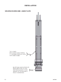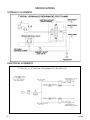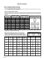
1
OPERATOR’S MANUAL WELD-ON HYDRAULIC THUMB SERIAL NUMBER: ___________________ MODEL NUMBER: ___________________ Manual Number: OM70M Rev: 800-433-6404 I www.paladinattachments.com 8822 Apison Pike, Ooltewah, TN 37363, United States of America Copyright © 9-4-13 TABLE OF CONTENTS PREFACE....................................................................................................................................................... 5 SAFETY PRECAUTIONS Safety Statements............................................................................................................................... 6 General Safety Precautions.............................................................................................................. 6-7 Equipment Safety Precautions......................................................................................................... 8-9 DECALS Decals & Decal Placement................................................................................................................ 10 INSTALLATION Required Tools....................................................................................................................................11 Machine Set-Up..................................................................................................................................11 Installing Thumb........................................................................................................................... 12-13 Welding Guidelines - Base Plate....................................................................................................... 14 Connecting Hydraulics....................................................................................................................... 15 OPERATION Intended Use..................................................................................................................................... 16 Operating the Attachment.................................................................................................................. 16 Storage.............................................................................................................................................. 17 Lift Points, Tie-Down Points & Transporting...................................................................................... 18 MAINTENANCE Maintenance Schedule...................................................................................................................... 19 Greasing the Attachment................................................................................................................... 19 TROUBLESHOOTING.................................................................................................................................. 20 SPECIFICATIONS Welding Specifications for Installation Process................................................................................. 21 Hydraulic & Electrical Schematics..................................................................................................... 22 Bolt Torque Specifications................................................................................................................. 23 LIMITED WARRANTY.................................................................................................................................. 25 OM70M 3 THIS PAGE IS INTENTIONALLY BLANK 4 OM70M PREFACE GENERAL COMMENTS Congratulations on the purchase of your new C&P product! This product was carefully designed and manufactured to give you many years of dependable service. Only minor maintenance (such as cleaning and lubricating) is required to keep it in top working condition. Be sure to observe all maintenance procedures and safety precautions in this manual and on any safety decals located on the product and on any equipment on which the attachment is mounted. This manual has been designed to help you do a better, safer job. Read this manual carefully and become familiar with its contents. WARNING! Never let anyone operate this unit without reading the "Safety Precautions" and "Operating Instructions" sections of this manual. Always choose hard, level ground to park the vehicle on and set the brake so the unit cannot roll. Unless noted otherwise, right and left sides are determined from the operator’s control position when facing the attachment. NOTE: The illustrations and data used in this manual were current (according to the information available to us) at the time of printing, however, we reserve the right to redesign and change the attachment as may be necessary without notification. BEFORE OPERATION The primary responsibility for safety with this equipment falls to the operator. Make sure the equipment is operated only by trained individuals that have read and understand this manual. If there is any portion of this manual or function you do not understand, contact your local authorized dealer or the manufacturer. Keep this manual available for reference. Provide this manual to any new owners and/or operators. SAFETY ALERT SYMBOL This is the "Safety Alert Symbol" used by this industry. This symbol is used to warn of possible injury. Be sure to read all warnings carefully. They are included for your safety and for the safety of others working with you. SERVICE Use only manufacturer replacement parts. Substitute parts may not meet the required standards. Record the model and serial number of your unit on the cover of this manual. The parts department needs this information to insure that you receive the correct parts. SOUND AND VIBRATION Sound pressure levels and vibration data for this attachment are influenced by many different parameters; some items are listed below (not inclusive): • prime mover type, age condition, with or without cab enclosure and configuration • operator training, behavior and stress level • job site organization, working material condition and environment Based on the uncertainty of the prime mover, operator and job site it is not possible to get precise machine and operator sound pressure levels or vibration levels for this attachment. NOTE: A list of all Paladin Patents can be found at http://www.paladinattachments.com/patents.asp. OM70M 5 SAFETY STATEMENTS THIS SYMBOL BY ITSELF OR WITH A WARNING WORD THROUGHOUT THIS MANUAL IS USED TO CALL YOUR ATTENTION TO INSTRUCTIONS INVOLVING YOUR PERSONAL SAFETY OR THE SAFETY OF OTHERS. FAILURE TO FOLLOW THESE INSTRUCTIONS CAN RESULT IN INJURY OR DEATH. DANGER THIS SIGNAL WORD IS USED WHERE SERIOUS INJURY OR DEATH WILL RESULT IF THE INSTRUCTIONS ARE NOT FOLLOWED PROPERLY. WARNING THIS SIGNAL WORD IS USED WHERE SERIOUS INJURY OR DEATH COULD RESULT IF THE INSTRUCTIONS ARE NOT FOLLOWED PROPERLY. CAUTION . HIS SIGNAL WORD IS USED WHERE MINOR INJURY COULD RESULT IF T THE INSTRUCTIONS ARE NOT FOLLOWED PROPERLY. NOTICE NOTICE INDICATES A PROPERTY DAMAGE MESSAGE. GENERAL SAFETY PRECAUTIONS WARNING! READ MANUAL PRIOR TO INSTALLATION Improper installation, operation, or maintenance of this equipment could result in serious injury or death. Operators and maintenance personnel should read this manual, as well as all manuals related to this equipment and the prime mover thoroughly before beginning installation, operation, or maintenance. FOLLOW ALL SAFETY INSTRUCTIONS IN THIS MANUAL AND THE PRIME MOVER’S MANUAL(S). READ AND UNDERSTAND ALL SAFETY STATEMENTS Read all safety decals and safety statements in all manuals prior to operating or working on this equipment. Know and obey all OSHA regulations, local laws, and other professional guidelines for your operation. Know and follow good work practices when assembling, maintaining, repairing, mounting, removing, or operating this equipment. KNOW YOUR EQUIPMENT Know your equipment’s capabilities, dimensions, and operations before operating. Visually inspect your equipment before you start, and never operate equipment that is not in proper working order with all safety devices intact. Check all hardware to ensure it is tight. Make certain that all locking pins, latches, and connection devices are properly installed and secured. Remove and replace any damaged, fatigued, or excessively worn parts. Make certain all safety decals are in place and are legible. Keep decals clean, and replace them if they become worn or hard to read. 6 OM70M GENERAL SAFETY PRECAUTIONS WARNING! PROTECT AGAINST FLYING DEBRIS Always wear proper safety glasses, goggles, or a face shield when driving pins in or out, or when any operation causes dust, flying debris, or any other hazardous material. WARNING! LOWER OR SUPPORT RAISED EQUIPMENT Do not work under raised booms without supporting them. Do not use support material made of concrete blocks, logs, buckets, barrels, or any other material that could suddenly collapse or shift positions. Make sure support material is solid, not decayed, warped, twisted, or tapered. Lower booms to ground level or on blocks. Lower booms and attachments to the ground before leaving the cab or operator’s station. WARNING! USE CARE WITH HYDRAULIC FLUID PRESSURE Hydraulic fluid under pressure can penetrate the skin and cause serious injury or death. Hydraulic leaks under pressure may not be visible. Before connecting or disconnecting hydraulic hoses, read your prime mover’s operator’s manual for detailed instructions on connecting and disconnecting hydraulic hoses or fittings. • Keep unprotected body parts, such as face, eyes, and arms as far away as possible from a suspected leak. Flesh injected with hydraulic fluid may develop gangrene or other permanent disabilities. • If injured by injected fluid, see a doctor at once. If your doctor is not familiar with this type of injury, ask him or her to research it immediately to determine proper treatment. • Wear safety glasses, protective clothing, and use a piece of cardboard or wood when searching for hydraulic leaks. DO NOT USE YOUR HANDS! SEE ILLUSTRATION. CARDBOARD HYDRAULIC HOSE OR FITTING FIG00001 MAGNIFYING GLASS OM70M 7 EQUIPMENT SAFETY PRECAUTIONS WARNING! KNOW WHERE UTILITIES ARE Observe overhead electrical and other utility lines. Be sure equipment will clear them. When digging, call your local utilities for location of buried utility lines, gas, water, and sewer, as well as any other hazard you may encounter. WARNING! EXPOSURE TO RESPIRABLE CRYSTALLINE SILICA DUST ALONG WITH OTHER HAZARDOUS DUSTS MAY CAUSE SERIOUS OR FATAL RESPIRATORY DISEASE. It is recommended to use dust suppression, dust collection and if necessary personal protective equipment during the operation of any attachment that may cause high levels of dust. WARNING! REMOVE PAINT BEFORE WELDING OR HEATING Hazardous fumes/dust can be generated when paint is heated by welding, soldering or using a torch. Do all work outside or in a well ventilated area, and dispose of paint and solvent properly. Remove paint before welding or heating. When sanding or grinding paint, avoid breathing the dust. Wear an approved respirator. If you use solvent or paint stripper, remove stripper with soap and water before welding. Remove solvent or paint stripper containers and other flammable material from area. Allow fumes to disperse at least 15 minutes before welding or heating. WARNING! END OF LIFE DISPOSAL At the completion of the useful life of the unit, drain all fluids and dismantle by separating the different materials (rubber, steel, plastic, etc.). Follow all federal, state and local regulations for recycling and disposal of the fluid and components. OPERATING THE ATTACHMENT • • • • • • • • 8 Never use your attachment for a work platform or personnel carrier. Do not exceed the lifting capacity of your prime mover. Operate only from the operator’s station. When operating on slopes, drive up and down, not across. Avoid steep hillside operation, which could cause the prime mover to overturn. Reduce speed when driving over rough terrain, on a slope, or turning, to avoid overturning the vehicle. An operator must not use drugs or alcohol, which can change his or her alertness or coordination. An operator taking prescription or over-the-counter drugs should seek medical advice on whether or not he or she can safely operate equipment. Never lift, move, or swing a load or attachment over anyone. Before exiting the prime mover, lower the attachment to the ground, apply the brakes, turn off the prime mover’s engine and remove the key. OM70M EQUIPMENT SAFETY PRECAUTIONS TRANSPORTING THE ATTACHMENT • Travel only with the attachment in a safe transport position to prevent uncontrolled movement. Drive slowly over rough terrain and slopes. • When driving on public roads use safety lights, reflectors, Slow Moving Vehicle signs etc., to prevent accidents. Check local government regulations that may affect you. • Do not drive close to ditches, excavations, etc., as a cave-in could result. MAINTAINING THE ATTACHMENT OM70M • Before performing maintenance (unless otherwise specified), lower the attachment to the ground, apply the brakes, turn off the engine and remove key. • Never perform any work on the attachment unless you are authorized and qualified to do so. Always read the operator service manuals before any repair is made. After completing maintenance or repair, check for correct functioning of the attachment. If not functioning properly, always tag “DO NOT OPERATE” until all problems are corrected. • Worn, damaged, or illegible safety decals must be replaced. New safety decals can be ordered from your local dealer or the manufacturer. • Never make hydraulic repairs while the system is under pressure. Serious personal injury or death could result. • Never work under a raised attachment. 9 DECALS DECAL PLACEMENT GENERAL INFORMATION The diagram below shows the location of decals used with the attachment. The decals are identified by their part numbers and with reductions of the actual decals. Use this information to order replacements for lost or damaged decals. Be sure to read all the decals before operating equipment. They contain information you need to know for both safety and product longevity. CAUTION! HYDRAULIC PRESSURE PART #TC001 WARNING! CLEARANCE HAZARD PART #TW001 IMPORTANT! LOAD IMBALANCE PART #TI001 SERIAL TAG LOCATION 3 2 1 ITEM QTY PART NUMBER 1 1 TW001 2 1 TI001 3 1 TC001 Decals can only be ordered as kit# TK03 IMPORTANT: Keep all safety decals clean and legible. Replace all missing, illegible or damaged safety decals. When replacing parts with safety decals attached, the safety decals must also be replaced. REPLACING SAFETY DECALS: Clean the area of application with nonflammable solvent, then wash the same area with soap and water. Allow surface to fully dry. Remove the backing from the safety decal, exposing the adhesive surface. Apply the safety decal to the positon shown in the diagram above and smooth out any bubbles. 10 OM70M INSTALLATION Thoroughly read and understand this manual before starting installation. There are many different types of attachments that can be used in combination with the thumb. Care should be taken in coordinating installation to coincide with the appropriate attachment (bucket, etc.) for the machine. WARNING! KEEP ALL UNNECESSARY PERSONNEL FROM INSTALLATION AREA. Attachment can drop without warning if not properly attached. Failure to do so could result in serious injury or death. REQUIRED TOOLS • Standard English and metric wrench sets • Standard English and metric Allen wrench sets • Phillips head and flat head screwdrivers • Two or more people • 8 lb. Hammer • Lift chain and strap • Grinder for weld preparation • Welder capable of 7018 low hydrogen or equivalent. • Wire cutters and crimpers • Measuring tape • Torque wrench MACHINE SET-UP: • Thoroughly clean the arm / bucket joint area at the end of the machine arm to avoid bearing contamination. • Disconnect battery before doing any welding on the machine. If possible, disconnect the onboard computer. Failure to do so could result in damage to the machine’s electrical system. • If using a coupler, ALWAYS remove the bucket from the coupler before installing the thumb. DO NOT remove the bucket or coupler from the machine arm. OM70M 11 INSTALLATION DO NOT WELD ACROSS WIDTH OF MACHINE ARM. Always weld parallel to the long axis of the arm. Failure to do so could result in weakening of the machine arm. PROTECT SURROUNDING AREA BEFORE WELDING Weld spatter can cause damage to components such as pins, cylinders, hydraulic hoses and fittings, etc. NOTE: See general welding specifications listed on page 21 before welding. INSTALLING THUMB Position the hydraulic thumb on the ground near the end of the machine arm. Move the machine arm to a position near the thumb. Place bucket in full curl up position. Locate thumb with approximately 1” between bucket and thumb bracket. Mark location. 1 Remove paint from machine arm along sides of thumb base plate parallel to the long axis of the arm. Tack weld (1) four corners and centers of the base plate. After locating and tacking the thumb base plate, position thumb over bucket to check alignment. Use bucket radius (2) and thumb radius (3) to check for clearance. With both of these attachments having two different pivot points it is important to check for proper fit throughout rotating range of thumb. 12 2 3 OM70M INSTALLATION Fully rotate the hydraulic thumb, checking for clearances before final welding. Be sure to re-check that all pins, nuts and bolts are installed and tightened. Improper alignment could impair thumb performance and cause damage to the machine arm and attachments. Once thumb is in proper location, proceed with final welding of base plate. Reference page 14 for further welding guidelines. OM70M 13 INSTALLATION WELDING GUIDELINES - BASE PLATE TYP. 2 PLACES WELD LENGTH SHOULD EXTEND 1”-2” BEYOND LENGTH OF PLATE & TAPER DOWN TO 0.08” 1/2” NO WELDING SHOULD BE APPLIED ACROSS BOTH ENDS OF PLATE. PERPENDICULAR WELD TO THE LONG AXIS OF THE ARM COULD RESULT IN WEAKENING. 14 N OM70M INSTALLATION CONNECTING HYDRAULICS 1. Before starting, consult the manual provided in the hydraulic kit for specific makes and models. 2. Turn off the machine engine and then turn the ignition key back to the ON position. DO NOT start the engine. Relieve the hydraulic pressure in the system. Turn the ignition key to the OFF position and remove it from the ignition switch. Following the machine service manual, bleed the air pressure from the hydraulic oil tank. The hydraulic oil pressure supply to operate the thumb will attach to the bucket cylinder retract circuit. Relieving all hydraulic pressure will minimize loss of hydraulic fluid. 3. Attach a vacuum pump to the machines hydraulic fluid reservoir to minimize drainage of hydraulic fluid. 4. Finish attaching all hydraulic hose and fittings needed for installation. Reference hydraulic hose requirements below. 5. Turn off vacuum pump and remove it from the hydraulic fluid reservoir. 6. Check that all hydraulic fittings are tight. Hydrauic pressure on the thumb cylinder should not exceed 2500 PSI. It is essential to ensure the bucket always overpowers the thumb. Refer to prime mover operator’s/service manual for procedures on checking and adjusting auxiliary circuit valve to the recommended pressure. OM70M 15 OPERATION INTENDED USE The thumb is designed to be used in conjunction with a specific attachment and machine type for loading, unloading and transporting objects or material. Use in any other way is considered contrary to the intended use. MISUSE Forms of misuse include, and are not limited to: using the thumb to “rake” material, to “push” or “pull” material, using the sides of the thumb to move material, using the thumb with rope/chain as a lifting device or using the thumb as a “pry bar” to dislodge objects. Misuse of the thumb may cause damage to the bucket, stick and boom and result in a loss of warranty and serious personal injury or death. OPERATING THE THUMB NOTE: If thumb is installed on an extendable stick, only operate with stick in the fully retracted position. Read all Safety Precautions before operating the equipment. Also refer to the prime mover operator’s manual for attachment operation. Buckets used in conjunction with the thumb may come from a different manufacturer. Always refer to the attachment manufacturer’s product manual for proper usage instructions. If a coupler is used with the thumb, refer to the coupler manufacturer’s product manual for proper usage instructions. • The operator should become familiar with the machine controls and how they function to operate the attachment. • DO NOT overload the bucket and thumb capacity or damage to the bucket, thumb and/or machine stick may result. • Close the thumb to the fullest extent possible and lift the attachment slightly to be certain the load is secure. NOTE: If the load appears to be unstable, lower the attachment to the ground, open the thumb and reposition the load to attain full stability. Repeat until full stability is achieved. Because a heavy load (rock or logs) can generate a great deal of momentum in side-to-side movements, the operator should always use caution and avoid sudden stops and starts. 16 OM70M OPERATION LOCKING THE THUMB (STORAGE POSITION) For applications when the thumb is not in use, it can be locked out of the way with the use of a lock pin. To lock the thumb: Remove quick pin and remove lock pin from stored position. Retract thumb until hydraulic cylinder is fully compressed. This should align holes in thumb body with holes in lock back bracket on stick. Reinsert lock pin and secure with quick pin. Lock Pin STORAGE: • • • • • • Clean the unit thoroughly, removing all mud, dirt, and grease. Apply a light coating of oil to all exposed metal parts to prohibit corrosion. Inspect for visible signs of wear, breakage, or damage. Order any parts required and make the necessary repairs to avoid delays upon removal from storage. Tighten loose nuts, capscrews and hydraulic connections. Seal hydraulic system from contaminants and secure all hydraulic hoses off the ground to help prevent damage Store unit in a dry and protected place. Leaving the unit outside will materially shorten its life. Additional Precautions for Long Term Storage: • Touch up all unpainted surfaces with paint to prevent rust REMOVAL FROM STORAGE: • • • • Remove cover Wash unit and replace any damage and/or missing parts Lubricate grease fittings Check hydraulic hoses for damage and replace as necessary OM70M 17 OPERATION LIFT POINTS Lifting points are identified by lifting decals where required. Lifting at other points is unsafe and can damage attachment. Do not attach lifting accessories around cylinders or in any way that may damage hoses or hydraulic components. • Attach lifting accessories to unit at any recommended lifting points. • Bring lifting accessories together to a central lifting point. • Lift gradually, maintaining the equilibrium of the unit. WARNING! Use lifting accessories (chains, slings, ropes, shackles and etc.) that are ca pable of supporting the size and weight of your attachment. Secure all lifting accessoriesin such a way to prevent unintended disengagement. Failure to do so could result in the attachment falling and causing serious personal injury or death. TIE DOWN POINTS Tiedown points are identified by tiedown decals where required. Securing to trailer at other points is unsafe and can damage attachment. Do not attach tie down accessories around cylinders or in any way that may damage hoses or hydraulic components. • Attach tie down accessories to unit as recommended. • Check unit stability before transporting. WARNING! Verify that all tiedown accessories (chains, slings, ropes, shackles and etc.) are capable of maintaining attachment stability during transporting and are attached in such a way to prevent unintended disengagement or shifting of the unit. Failure to do so could result in serious personal injury or death. TRANSPORTING Follow all local government regulations that may apply along with recommended tiedown points and any equipment safety precautions at the front of this handbook when transporting your attachment. 18 OM70M MAINTENANCE GENERAL INFORMATION Regular maintenance is the key to long equipment life and safe operation. Maintenance requirements have been reduced to an absolute minimum. However it is very important that these maintenance functions be performed as described below. Read and follow all safety precautions before performing any maintenance or troubleshooting on this equipment. MAINTENANCE SCHEDULE PROCEDURE DAILY Remove debris from attachment Check that pins and pin locking hardware are secure Lubricate grease points WEEKLY Check attachment for cracked, bent or broken components and distressed welds Check hydraulic hoses/components for leaks and/or damage Ensure daily checks are carried out NOTES Primarily around cylinder Refer to torque table Reference diagram below for grease point locations. In extreme conditions, such as heavy dust or underwater use, lubricate every 4 hours. Clean attachment thoroughly before inspection. If a crack is found in either the steel structure or welds, the attachment must be removed from the machine and the manufacturer contacted immediately. Replace broken or missing parts if required. GREASING THE ATTACHMENT 3 To keep the attachment in proper working condition, it must be greased on a daily basis. Grease points on the attachment are as shown. If any grease fittings are missing or damaged, replace and grease. 2 NOTE: Cylinders and pins that are supplied without grease zerks DO NOT need to be greased. 1 - Main Pin 2 - Cylinder Rod 3 - Cylinder Base OM70M 1 19 TROUBLESHOOTING PROBLEM Thumb cylinder does not extend or retract properly. 20 POSSIBLE CAUSE Hoses or valves are plugged by dirt. POSSIBLE REMEDY Remove hoses and valve. Clean hoses and valve spool. Blow air through valve to check operation. OM70M SPECIFICATIONS WELDING SPECIFICATIONS FOR INSTALLATION PROCESS The sole purpose of this section is to provide specific details and instruction for the installation process of the thumbs stated within. Articles to be addressed are as follows: • Approved Welding Process/Electrodes and Protection - (SMAW/GMAW) • Weld Quality - VWI (AWS D1.1. 2004 Edition) • Specific Weld Sizes and Locations Article I. Section 1.01 Approved Welding Process/Electrodes and Protection The SMAW or GMAW process is suited for the installation process of all thumbs produced by C&P. If an SMAW process is chosen for this installation, the type of electrode to be utilized is an E7018. Refer to AWS D1.1 Section 5.3.2.1, 2004 Edition for Low - Hydrogen Electrode Storage Condtions The conditions for maintaining the specified electrodes shall be satisfied prior to the installation process. If the GMAW process is utilized, the classification strength of the filler metal should meet the same characteristics/properties as that of the E7018 of the SMAW process. Article II. Section 2.01 Weld Quality - (VWI) To insure the highest level of quality is provided a Visual Weld Inspection should be performed after the welding process is complete. This process should be performed in accordance with AWS D1.1 Section 4.8.1 Visual Inspection. If any discontinuities or discrepancies are identified they should be repaired in accordance to AWS D1.1, Section 5.26 Repairs. Article III. Section 3.01 Specific Weld Sizes and Locations Refer to page 14 for specific weld sizes and locations. OM70M 21 SPECIFICATIONS HYDRAULIC SCHEMATIC ELECTRICAL SCHEMATIC 22 OM70M SPECIFICATIONS BOLT TORQUE SPECIFICATIONS BOLT TORQUE SPECIFICATIONS GENERAL TORQUE SPECIFICATION TABLES Use the following charts when determining bolt torque specifications when special torques are not given. Always use grade 5 or better when replacing bolts. SAE BOLT TORQUE SPECIFICATIONS NOTE: The following torque values are for use with extreme pressure lubricants, plating or hard washer applications Increase torque 15% when using hardware that is unplated and either dry or lubricated with engine oil. SAE GRADE 5 TORQUE Bolt Size Inches Millimeters 1/4 5/16 Pounds Feet UNC UNF Newton-Meters UNC UNF SAE GRADE 8 TORQUE Pounds Feet UNC UNF 6.35 7.94 8 14 9 17 11 19 12 23 10 20 13 25 14 27 18 34 62 3/8 9.53 30 36 41 49 38 46 52 7/16 11.11 46 54 62 73 60 71 81 96 1/2 12.70 68 82 92 111 94 112 127 152 9/16 14.29 94 112 127 136 163 184 221 5/8 15.88 128 153 174 207 187 224 254 304 3/4 19.05 230 275 312 373 323 395 438 536 7/8 22.23 340 408 461 553 510 612 691 830 1 25.40 493 592 668 803 765 918 1037 1245 1-1/8 25.58 680 748 922 1014 1088 1224 1475 1660 1-1/4 31.75 952 1054 1291 1429 1547 1700 2097 2305 1-3/8 34.93 1241 1428 1683 1936 2023 2312 2743 3135 1-1/2 38.10 1649 1870 2236 2535 2686 3026 3642 4103 152 Bolt head identification marks as per grade. NOTE: Manufacturing Marks Will Vary Newton-Meters UNC UNF METRIC BOLT TORQUE SPECIFICATIONS NOTE: The following torque values are for use with metric hardware that is unplated and either dry or lubricated with engine oil. Reduce torque 15% when using hardware that has extreme pressure lubricants, plating or hard washer applications. Bolt head identification marks as per grade. Size of Bolt Grade No. Pitch (mm) Pounds Feet Newton-Meters Pitch (mm) Pounds Feet Newton-Meters M6 5.6 8.8 10.9 1.0 3.6-5.8 5.8-.4 7.2-10 4.9-7.9 7.9-12.7 9.8-13.6 - - - M8 5.6 8.8 10.9 1.25 7.2-14 17-22 20-26 9.8-19 23-29.8 27.1-35.2 1.0 12-17 19-27 22-31 16.3-23 25.7-36.6 29.8-42 M10 5.6 8.8 10.9 1.5 20-25 34-40 38-46 27.1-33.9 46.1-54.2 51.5-62.3 1.25 20-29 35-47 40-52 27.1-39.3 47.4-63.7 54.2-70.5 M12 5.6 8.8 10.9 1.75 28-34 51-59 57-66 37.9-46.1 69.1-79.9 77.2-89.4 1.25 31-41 56-68 62-75 42-55.6 75.9-92.1 84-101.6 M14 5.6 8.8 10.9 2.0 49-56 81-93 96-109 66.4-75.9 109.8-126 130.1-147.7 1.5 52-64 90-106 107-124 70.5-86.7 122-143.6 145-168 M16 5.6 8.8 10.9 2.0 67-77 116-130 129-145 90.8-104.3 157.2-176.2 174.8-196.5 1.5 69-83 120-138 140-158 93.5-112.5 162.6-187 189.7-214.1 M18 5.6 8.8 10.9 2.0 88-100 150-168 175-194 119.2-136 203.3-227.6 237.1-262.9 1.5 100-117 177-199 202-231 136-158.5 239.8-269.6 273.7-313 M20 5.6 8.8 10.9 2.5 108-130 186-205 213-249 146.3-176.2 252-277.8 288.6-337.4 1.5 132-150 206-242 246-289 178.9-203.3 279.1-327.9 333.3-391.6 OM70M 10360 3-20-08-3 23 THIS PAGE IS INTENTIONALLY BLANK 24 OM70M Limited Warranty Paladin Heavy Construction (“Paladin”) warrants its products against faulty design, material, and workmanship for a period of one (1) year from date of delivery or 2,000 hours, whichever comes first. Standard Series Loader Couplers are warranted for three (3) years or 3,000 hours, whichever comes first. Special Interchange Loader Couplers and Excavator Couplers are warranted for a period of one (1) year from date of delivery or 1,000 hours, whichever comes first. Hydraulic kits and components are warranted for one (1) year from factory delivery date. Cylinders must be returned in their entirety and not have been disassembled to be considered for warranty. After Warranty and Purchased Parts include cylinders, hydraulic valves, seal kits, electrical components and wear parts are warranted for 90 days. Disassembly, modification or welding of cylinders without Paladin’s written authorization voids the warranty on the cylinder and the seals. All valves must be packaged and sealed to prevent contaminates from entering the valve during shipment. Valves improperly packaged will not be considered for warranty. Hydraulic hoses are warranted against failure due to workmanship. Improper installation, ripping or cutting due to unauthorized modifications of Paladin Heavy Construction installation procedures is not warranted. A qualified Paladin dealer or Paladin representative must install hydraulic kits and components for failures to be given warranty consideration. Paladin will repair or replace, at its sole option, any equipment proven to Paladin’s satisfaction to be of faulty design, material or workmanship. Warranty replacement parts will be shipped second day air. This warranty does not include or cover purchased subassemblies including, but not limited to, teeth, tines (forks), cylinders, blades, etc. Such purchase subassemblies are covered only by the OEM’s warranty, if any, of their respective manufacturers, and not by Paladin. Claims received 30 days past the repair date will not be considered for warranty coverage and shall be null and void. LIMITATIONS AND EXCLUSIONS: This LIMITED WARRANTY does not cover product, which in the opinion of Paladin, is damaged due to abuse, misuse, misapplication, prohibited operation, improper maintenance, alteration, unauthorized service, contamination by the base machine, or normal wear and tear. This LIMITED WARRANTY is void if the product is modified in any way without the written consent or instruction of Paladin. This LIMITED WARRANTY is null and void if the product is used in a prohibited operation, or unauthorized adjustment/assembly/disassembly has occurred. This LIMITED WARRANTY is the exclusive warranty and is given in lieu of any and all other warranties, whether expressed or implied, arising in any fashion including but not limited to the course of dealing and course of performance, and including but not limited to warranty of merchantability or warranty of fitness for a particular purpose. Dealers or Agents of Paladin have no authority to make any type of representation or warranties on behalf of Paladin beyond those expressly set forth in this document. Paladin Heavy Construction couplers are manufactured with a patented design to interface with Paladin attachments, OEM attachments and Paladin female adapters (ribs). The use of attachments other than Paladin attachments, OEM attachments and Paladin female adapters (ribs) will void all warranty on the Paladin Heavy Construction coupler. The use of Paladin Heavy Construction adapters on unapproved attachments is not sanctioned. A “home made” or nonstandard attachment outside the specifications for the machine will void the warranty on the Paladin Heavy Construction coupler. In no event shall Paladin be liable to any party, including but not limited to buyer, for any direct, incidental, consequential, punitive, or special damages, including but not limited to loss of profits, loss of productivity, in any way related to or arising, directly or indirectly, from the product. The liability of Paladin for any and all losses and damages to buyer, its successors and assigns, resulting from any cause whatsoever, including the negligence of Paladin, irrespective of whether such defects are discoverable or latent, shall in no event exceed the purchase price of the product with respect to which such losses or damages are claimed. Attachment Technologies Inc., a subsidiary of Paladin Brands Holding, Inc. (PBHI) is referred to herein as Paladin Heavy Construction. 1 OM70M 25