1
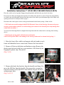
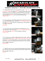
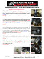
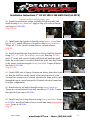
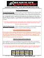
Installation Instructions 7” Lift Kit 2015 F150 4WD ONLY(44-2575) IF YOUR ReadyLIFT® OFF ROAD SUSPENSION PRODUCT IS MISSING A PART OR HAS A DAMAGED PART, PLEASE CONTACT CUSTOMER SERVICE DIRECTLY. A NEW REPLACEMENT PART WILL BE SENT TO YOU IMMEDIATELY (800) 549-4620 MON-FRI 7AM-5PM PST OR EMAIL: [email protected] WEBSITE: www. ReadyLIFT.COM **Please retain this document in your vehicle at all times** ReadyLIFT® Off Road Suspension Limited Warranty Limited Warranty details for ReadyLIFT® Off Road Suspension. The ReadyLIFT® Off Road Suspension Limited Lifetime Warranty covers defective materials or defective workmanship for the life of the product to the original purchaser and only on the original vehicle which the product was installed. The ReadyLIFT® Off Road Suspension Limited Lifetime Warranty excludes the following wearable items: bushings, bushing sleeves, bump stops, top-out stops, spherical bearings (uniballs), heim joints (rod ends), and misalignment spacers (upper control arm and steering). These items are considered wear items and are covered for 90 days from the original purchase date, therefore these items will not be considered defective because of wear. Wear is subject to use of product, use of vehicle, driving conditions, weather conditions, cleanliness of product/components, and maintenance/up-keep. The degree of wear and overall lifetime of each wear item is subject to afore mentioned conditions and circumstances. ReadyLIFT® Off Road Suspension will only warranty wear items in the case of workmanship and defects for the period of 90 days following the date of purchase. Please note that all products should be inspected by a professional technician before installing any part/kit onto the vehicle. In addition, all products should be installed by a qualified technician. Please contact ReadyLIFT® Off Road Suspension if there is any question as to the quality of workmanship of each component or its installation procedure. Contact ReadyLIFT® Off Road Suspension directly about any potentially defective parts prior to removing any parts from the vehicle. If it appears that the part is warrantable, you will be given an RGA number and asked to return the part freight prepaid. If the part is found to be warrantable, at the sole discretion of ReadyLIFT® Off Road Suspension, it will be repaired or replaced and returned to you. The limited warranty expressed by ReadyLIFT® Off Road Suspension supersedes that of any claims made by authorized and unauthorized dealers of ReadyLIFT® Off Road Suspension products. www.ReadyLIFT.com 8‐28‐15 MMC www.ReadyLIFT.com - Phone: (800) 549-4620 Installation Instructions 7” Lift Kit 2015 F150 4WD ONLY(44-2575) Please read Instructions thoroughly and completely before beginning installation. Installation by a certified mechanic is recommended. ReadyLIFT® Off Road Suspension is NOT responsible for any damage or failure resulting from improper installation. Safety Warning: Suspension systems or components that enhance the on and off-road performance of your vehicle may cause it to handle differently than it did from the factory. Extreme care must be used to prevent loss of control or vehicle rollover during abrupt maneuvers. Always operate your vehicle at reduced speeds to ensure your ability to control your vehicle under all driving conditions. Failure to drive safely may result in serious injury or death to driver and passengers. Driver and passengers must ALWAYS wear your seat belts, avoid quick sharp turns and other sudden maneuvers. ReadyLIFT® Off Road Suspension does not recommend the combined use of suspension lifts, body lifts, or other lifting devices. You should never operate your vehicle under the influence of alcohol or drugs. Constant maintenance is required to keep your vehicle safe. Thoroughly inspect your vehicle before and after every off-road use. It is the responsibility of the retailer and/or the installer to review all state and local laws, with the end user of this product, related to bumper height laws and the lifting of their vehicle before the purchase and installation of any ReadyLIFT® products. It is the responsibility of the driver/s to check their surrounding area for obstructions, people, and animals before moving the vehicle. All raised vehicles have increased blind spots and damage, injury and/or death can occur if these instructions are not followed. Installation Warning: All steps and procedures described in these instructions were performed while the vehicle was properly supported on a two post vehicle lift with safety jacks. Use caution during all disassembly and assembly steps to insure suspension components are not over extended causing damage to any vehicle components and parts included in this kit. Included instructions are guidelines only for recommended procedures and are not meant to be definitive. Installer is responsible to insure a safe and controllable vehicle after performing modifications. This suspension system was developed using a 35” x 12.5” tire with 20” x 9” wheel and a offset of +25mm. If wider tires are used, offset wheels may be necessary and trimming may be required. Factory wheels can be used but are not recommended with tires over 11” wide. The stock spare rim can be run in an emergency. Please note that if running the spare factory tire, it is done for short distances and a speed not to exceed 45mph or damage to differentials may occur. VEHICLE MEASURMENTS Driver Front: 8‐28‐15 MMC Driver Rear: Pass. Front: Pass. Rear: www.ReadyLIFT.com - Phone: (800) 549-4620 2 Installation Instructions 7” Lift Kit 2015 F150 4WD ONLY(44-2575) 8‐28‐15 MMC www.ReadyLIFT.com - Phone: (800) 549-4620 3 Installation Instructions 7” Lift Kit 2015 F150 4WD ONLY(44-2575) 8‐28‐15 MMC www.ReadyLIFT.com - Phone: (800) 549-4620 4 Installation Instructions 7” Lift Kit 2015 F150 4WD ONLY(44-2575) Bill of Materials 44‐2575‐1 (Box 1 of 7) Assembly, Front Cross Member Assembly, Rear Cross Member Hardware Pack, F&R Cross Member Bolt, 18mm x 2.5 x 150mm, 10.9 Hex Head Bolt, 18mm x 2.5 x 140mm, 10.9 Hex Head Cam Adj Plate and Nut Nut, m18‐2.5 Stover Washer, M18 washer, flat 48‐2351 Front Differential Skid Plate 48‐2937 Front Skid Plate Hardware Pack Bolt, Grade 8, 3/8" ‐ 16 x 1.00", Hex Head Washer, 3/8" Grade 8, Flat 48‐2910 Instructions and Warranty 44‐2575‐2 (Box 2 of 7) 48‐2403 Steering Knuckle ‐ Pass Side 44‐2575‐3 (Box 3 of 7) 48‐2402 Steering Knuckle ‐ Driver Side 44‐2575‐4 (Box 4 of 7) 48‐2301 Differential Drop, Pass Side 48‐2300 Differential Drop, Driver Side 48‐2305 Differential Support Bracket 48‐2931 Hardware Pack, Diff Breather 5/16" Barbed Straight Connector 5/16" Neoprene Rubber Tubing 48‐2315 Steering Extension Assembly 48‐2303‐5 Steering Extension Shaft 48‐2303‐2 Universal Joint 48‐2303‐4 Rod End, 3/4" x 3/4" Set Screws—Pre‐installed 48‐2360 Front Driveshaft Spacer 48‐2936 Hardware Pack, Ft Driveshaft Bolt,10mm x 1.5 x 100mm, Allen 48‐2115 48‐2215 48‐2905 1 1 1 2 4 4 2 8 1 1 6 6 1 1 1 1 1 1 1 1 1 1 1 1 1 1 1 6 44‐2575‐4 (Box 4 of 7) Continued Hardware PK, Diff ‐ Steer Bolt, 14mm‐2.0 x 90mm Allen Screw Washer, 14mm Flat Bolt, 9/16"‐18 x 4.0", HHB, GB YZ Nut, 9/16"‐18, Stover, G8, YZ Washer, 9/16", Flat, G8 48‐2306 Sway Bar Drop Brackets 48‐2307 Sway Bar Drop Brackets 48‐2950 Hardware Pack, SB Drop Bracket Bolt, 7/16" ‐ 14 x 1.25", G8Hex Head Washer, Flat, 7/16 Grade 8 Nut, 7/16" ‐ 14, Grade 8 Crimp Lock 48‐2601 Brake Line Support Bracket ‐ Front 48‐2961 Hardware Pack , Brake Lines Bolt, 5/16" ‐ 18 x 1", G8 Hex Head Washer, Flat, 5/16 Grade 8 Nut, 5/16" ‐ 18, Grade 8 Crimp Lock M6‐1.0 ‐ 16MM M6, Washer, Flat Zip Tie 48‐2610 R. Brake Bracket 48‐2621 R. E Brake Brackett 26‐2505 5" Rear Blocks Pair Left and Right Set of 4 U‐Bolts w/Nuts and Washers 44‐2505 Front 7" Strut Spacers ‐ Pair Nut, M10‐1.25, Serrated Flange, 10.9 Nut, M10‐1.50, Serrated Flange, 10.9 93‐2057R Rear Shocks 48‐2920 Lower Ball Joint Spacer (5mm Thick) 48‐2941 1 1 1 3 3 6 1 1 1 4 8 4 2 1 4 8 4 2 2 6 1 1 1 1 1 6 6 2 2 Safety Warning Before you start installation: ReadyLIFT® Off Road Suspension highly recommends that the installation of this product be performed by a professional mechanic with experience working on and installing suspension products. Professional knowledge and skill will typically yield the best installation results. If you need an in‐ staller in your area, please contact ReadyLIFT® Suspension customer service to find one of our “Pro‐Grade” Dealers. Notes: Installation by a professional mechanic is highly recommended. A Factory Ford Service Manual for your specific Year / Make / Model is highly recommended for reference during installation. Installation requires cutting and welding of the vehicle frame. Vehicles with a two piece rear driveline may require a carrier bearing drop support bracket, call technical assistance for details. Vehicles achieving more than 5” of rear lift may require rear driveline modifications, call technical assistance for details. All lifted vehicles may require additional driveline modifications and or balancing. A four wheel vehicle alignment will need to be performed after installation of this product. Speedometer / Computer recalibration is required if changing +/‐ 10% from factory tire diameter. Use of a Vehicle Hoist will greatly reduce installation time. Vehicle must be in excellent operating condition. Repair or replace any and all worn or damaged components prior to installation. 8‐28‐15 MMC www.ReadyLIFT.com - Phone: (800) 549-4620 5 Installation Instructions 7” Lift Kit 2015 F150 4WD ONLY(44-2575) Place the vehicle on level ground. Engage the parking brake and block the rear wheels for safety. Record stock vehicle ride height measurements on both the front and the rear, this will provide and guideline on vehicle rake and lift height. Measure from the center of the wheel up to the bottom edge of the fender well opening and record on chart provided on page 2. Disconnect the vehicle power source at the ground terminal on the battery using a 10mm socket. ***2011 and newer models equipped with EPAS (Electronic Power Assist Steering), disconnect the power steering control module connector to avoid arching of the contacts in the internal power relay during disassembly and reassembly*** You must Lock Steering Wheel in straight forward position with the column lock or steering wheel locking device. ***Rotating the steering wheel while disconnected from the vehicle rack & pinion WILL cause damage to the steering column and /or internal clock spring.*** 1. Raise the front of the vehicle and support with jack stands at each frame rail behind the lower control arms. Remove the front wheels. 2. Remove all factory skid plates and hardware using. Remove the plastic guard in between the two cross members of the frame by unclipping the plastic clips. Discard all. (Fig 1 A, B) Fig 1 B Fig 1 A 3. Remove the brake line brackets from the knuckle and frame. Remove the ABS line from the knuckle. Disconnect the vacuum line from the actuator on the backside of the knuckle. Repeat for driver and passenger sides. (Fig 2 A, B, C) Fig 2 A 8‐28‐15 MMC Fig 2 B Fig 2 C www.ReadyLIFT.com - Phone: (800) 549-4620 6 Installation Instructions 7” Lift Kit 2015 F150 4WD ONLY(44-2575) Repeat for driver and passenger sides 4. Disconnect the ABS wires from the engine compartment and remove from brake line brackets. Unclip electrical connectors from plastic holders to gain slack for reassembly later. (Fig 3 A, B) Fig 3 A Fig 3 B 5. Remove the tie rods from the knuckle. Strike the tie rod boss on the knuckle with a dead blow hammer to dislodge the taper from the knuckle. (Fig 4) Fig 4 6. Remove the brake caliper anchor bracket bolts using a. Remove the caliper from the knuckle and hang the out of the way using a S‐ Hook or suitable strap. DO NOT let the caliper hang by the brake hose. (Fig 5) Fig 5 7. Remove the brake rotor and dust shield. (Fig 6) 8. Remove the axle nut dust cover. Then remove the axle nut. (Fig 7 A, B) Fig 7 A 8‐28‐15 MMC Fig 6 Fig 7 B www.ReadyLIFT.com - Phone: (800) 549-4620 7 Installation Instructions 7” Lift Kit 2015 F150 4WD ONLY(44-2575) Repeat for driver and passenger side 9. Loosen the upper ball joint nut. Strike the ball joint boss on the knuckle with a dead blow hammer to dislodge the taper. Remove the upper ball joint nut and separate the upper control arm ball joint from the knuckle. Remove the hardware holding the vacuum actuator on the knuckle and slide it and the axle off to the side. Carefully remove the vacuum hub from the axle. USE CAUTION TO NOT DAMAGE THE VACUUM ACTUATOR. Loosen the lower ball joint nut. Strike the ball Fig 8 joint boss on the knuckle with a dead blow hammer to dislodge the taper and slide the knuckle off of the ball joint. (Fig 8) Fig 9 A Fig 9 B 10. Remove the sway bar end link and strut from the lower control arm. (Fig 9 A, B) 11. Remove the lower control arms. (Fig 10) Fig 10 12. Remove the strut from the frame. (Fig 11) Fig 11 8‐28‐15 MMC www.ReadyLIFT.com - Phone: (800) 549-4620 8 Installation Instructions 7” Lift Kit 2015 F150 4WD ONLY(44-2575) Repeat for driver and passenger side 13. Remove the sway bar from the frame. (Fig 12) Fig 12 14. Remove the rear cross member from the frame. Discard cross member and driver side hardware. They will not be reused. Save passenger side hardware. (Fig 13) Fig 13 15. Mark driveshaft to differential location for reinstall later. (Fig 14) 16. Remove the driveshaft mounting bolts. Remove from the front differential. Allow the driveshaft to rest out of the way. (Fig 15) Fig 14 17. Remove both the driver side and passenger side CV axle. Strike the shaft with a mallet or soft hammer to dislodge it from the c-clip. Fig 15 This step makes handling the differential much easier, but is not necessary. (Fig 16) ***Warning: The front differential is heavy and awkward. It is best removed by two people. Do not tilt the differential towards the opening on the driver side as gear oil will spill out.*** 8‐28‐15 MMC Fig 16 www.ReadyLIFT.com - Phone: (800) 549-4620 9 Installation Instructions 7” Lift Kit 2015 F150 4WD ONLY(44-2575) 18. Support the differential with a suitable jack. Remove the vent tube. Remove the 3 differential mounting bolts from the frame and lower differential out of vehicle. (Fig 17 A, B, C) Fig 17 A Fig 17 B 19. Locate the rack & pinion coupler pinch bolt. Mark the alignment of the rack and pinion input shaft and the coupler. Remove the pinch bolt and separate. (Fig 17 C) Fig 17 C 20. Disconnect the electrical leads to the rack and pinion. (Fig 18) Fig 18 21. With the rack supported, locate the two large bolts that hold the rack & pinion to the vehicle frame and remove. Carefully lower the rack & pinion assembly from the vehicle. (Fig 19) Fig 19 8‐28‐15 MMC www.ReadyLIFT.com - Phone: (800) 549-4620 10 Installation Instructions 7” Lift Kit 2015 F150 4WD ONLY(44-2575) Front Installation 22. The driver’s side rear lower control arm frame pocket must be modified to provide clearance for the differential in its relocated position. On the front and back side of the frame pocket measure from the outside edge 2 5/8”. Mark a vertical cut line at the mark, all the way to the bottom. Connect the 2 lines across the top of the pocket. Using a suitable cutting tool, cut this pocket off the frame. Sand and Fig 20 paint exposed metal with quality rust preventative paint. (Fig 20) 23. Locate the upper differential frame mount. Mark a line across the center of the mount. Make a cut to the frame. Cut the front half off the frame and sand flush with the frame. Paint exposed metal with quality rust preventative paint. This cut is for clearance of the steering shaft extension and u-joint. Fig 21 (Fig 21) 24. Locate the driver side differential drop bracket and the 3/4” rod end. Install the rod end into the pinch bung on the drop bracket. Set the distance from the edge of the pinch bung to the middle of the rod end to 1 3/4”. Set the rod end horizontal to the lower mounting bolt holes. Torque the pinch bung Allen bolt to 95 in-lbs using 3/16” Al- Fig 22 len tool. (Fig 22) 25. Install the completed driver side drop bracket into the factory location using the 14mm x 90mm Allen bolt and flat washer from bag (48-2941). Do not tighten at this time. Fig 23 (Fig 23) 26. Locate passenger side differential drop bracket and install into the factory location using factory bolt and flag nut. Do not tighten at this time. (Fig 24) 8‐28‐15 MMC Fig 24 www.ReadyLIFT.com - Phone: (800) 549-4620 11 Installation Instructions 7” Lift Kit 2015 F150 4WD ONLY(44-2575) 27. Install differential onto the drop brackets using 2, 9/16” x 4” bolts, and 2 washers from bag 48-2941 from the front of the vehicle facing the rear. Do not install the 2nd washer and nut at this time. Rack and pinion shown for illustration purposes. Install vent tube extension from bag 48-2931 onto vent tube and differential. (Fig 25 A, B) Fig 25 A 28. Locate passenger side differential brace and install onto passenger differential drop bracket. Install the 9/16” 2nd washers and c-nuts from bag 48-2941 onto both driver and passenger side drop bolts. Do not tighten at this time. (Fig 25 B) Fig 25 B 29. Locate the sway bar drop brackets. Install brackets to corresponding sides of the frame using 7/16” x 1 1/4” bolts, flat washers, and c-nuts from bag 48-2950. Do not tighten at this time. (Fig 26 A, B) Fig 26 A 30. Locate rear cross member and install into the factory control arm frame pockets using 18mm x 150mm bolts, flat washers, and c-nuts from bag 48-2905. Go through the sway bar drop brackets and then the factory control arm frame pockets from the rear of the vehicle. Do not tighten at this time. (Fig 26 A, B) Fig 26 B 31. Install factory rear cross member bolts and nuts into the passenger side frame pocket and into passenger differential support bracket. Do not tighten at this time. (Fig 27) Fig 27 8‐28‐15 MMC www.ReadyLIFT.com - Phone: (800) 549-4620 12 Installation Instructions 7” Lift Kit 2015 F150 4WD ONLY(44-2575) 32. Install rear differential mount using 9/16” x 4” bolt, flat washers, and c-nut from bag 48-2941. Do not tighten at this time. (Fig 28) 33. Locate and install front cross member using the factory control arm bolts and nuts from the rear of the vehicle facing forward. Do not tighten at this time. (Fig 29) Fig 28 Fig 29 34. Locate the steering u-joint assembly. Install the complete assembly onto the rack and pinion. Torque the u-joint Allen pinch bolt to 165 in-lbs. (Fig 30) Fig 30 35. Install the rack and pinion unit onto the front cross member using the factory bolts, lining up the steering extension through the 3/4” rod end. Attach factory intermediate shaft to extension using factory pinch bolt. Use a drop of Loctite on pinch bolt. Torque to 165 in-lbs. Plug electrical connectors into rack and pinion. Front differential not shown for picture taking purposes. Do not tighten main Fig 31 A bolts at this time. (Fig 31 A, B, C) Fig 31 B 8‐28‐15 MMC Fig 31 C www.ReadyLIFT.com - Phone: (800) 549-4620 13 Installation Instructions 7” Lift Kit 2015 F150 4WD ONLY(44-2575) 36. Install driver and passenger axles at this time if removed by sliding them together with the differential until c-clip engages. 37. Install driver and passenger side lower control arms into corresponding sides of the cross members using 18mm x 140mm, flat washer, cam bracket and cam nut from bag 48-2905. Bolts facing to the ends of the vehicle and cam plates on the outside of the cross member. Do not tighten at this time. (Fig 32) Fig 32 38. Tighten all differential, rack and pinion, and cross member hardware at this time. Starting with differential, torque all differential hardware to 95 ft-lbs, differential brace to cross member to 45 ft-lbs, cross member main hardware to 200 ft-lbs, torque sway bar drop bracket hardware to 60 ft-lbs, torque the rack and pinion to front Fig 33 A cross member hardware to 150 ft-lbs. (Fig 33 A, B, C, D, E) Fig 33 C Fig 33 D Fig 33 B Fig 33 E 39. Install the front skid plate 48-2351 using 3/8” x 1” hardware from bag 48-2937 and 9/16” socket. Torque to 35 ft-lbs. (Fig 34) Fig 34 40. Install driveshaft spacer and driveshaft in the same orientation with the marks made in step 15 using the 10mm x 100mm Allen head bolts from bag 48-2936. Apply Loctite to all bolts. Torque hardware to 76 ft-lbs. (Fig 35) Fig 35 8‐28‐15 MMC www.ReadyLIFT.com - Phone: (800) 549-4620 14 Installation Instructions 7” Lift Kit 2015 F150 4WD ONLY(44-2575) Repeat for driver and passenger sides 50. Install the driver and passenger side strut spacers to their corresponding struts using supplied 10mm x 1.50 flange nuts and 14mm socket. They are marked D for drivers and P for passenger. Torque to 35 ft-lbs. (Fig 36) Fig 36 51. Install completed strut assemblies into vehicle frame and lower control arms in their corresponding locations using supplied 10mm x 1.25 flange nuts from 44-2507, factory lower hardware. Torque upper nuts to 35 ft-lbs and lower nuts to 90 ft-lbs. (Fig 37) Fig 37 52. Locate Readylift driver knuckle and factory driver knuckle. Remove hub assembly. Inspect the mounting surface for any corrosion or dirt and clean as necessary. Install to aftermarket knuckle in the same orientation using factory hardware. Torque to 148 ft-lbs. Repeat procedure for the passenger knuckle 48-2403. (Fig 38) Fig 38 53. Locate the vacuum hub assembly and place onto the factory axle. (Fig 39) 54. Install new knuckles onto the lower ball joints using factory ball joint nut, 3/4” thick washer from bag 48-2920. Run tight at this time. Will torque in later step. Fig 39 (Fig 40 A, B, C) Fig 40 A 8‐28‐15 MMC Fig 40 B Fig 40 C www.ReadyLIFT.com - Phone: (800) 549-4620 15 Installation Instructions 7” Lift Kit 2015 F150 4WD ONLY(44-2575) *** Important*** Read and understand following steps. Failure to do so may result in broken or damaged vacuum actuator.*** Repeat for driver and passenger side 55. Raise knuckle towards upper control arm while guiding the axle shaft into the hub assembly. Take vacuum actuator and move to knuckle mounting surface making sure to engage the splined inner ring to the hub assembly and that the vacuum ports are pointing to the top of the knuckle. Once engaged to splines, install upper ball joint to knuckle using factory ball joint nut. Leave loose at this time. Install vacuum actuator using factory hardware. Torque to 5 ft-lbs. Fig 41 A Grab axle and pull towards the hub assembly while rotating the hub to engage the splines of the axle with the vacuum actuator. Once the splines have been engaged, install factory axle nut. Torque to 18 ftlbs. You will be able to tell if the axle has been fully engaged to vacuum actuator and hub assembly when the shoulder of the axle is visible through the hub and when rotating hub assembly the axle will rotate also. The shoulder should be 2mm under the nut mounting surface. If this is not the case, then the hub assembly will need to be ro- Fig 41 B tated more until full engagement of splines. These steps are very important to follow. The vacuum actuator is made of plastic and is very easily damaged. Repeat steps for driver and passenger sides. (Fig 41 A, B, C, D) Fig 41D Fig 41C 56. Install the ABS sensor onto the hub assembly using factory Allen bolt hardware. Torque to 5 ft-lbs. Repeat for driver and passenger sides (Fig 42) Fig 42 57. Install dust shield to knuckle using factory hardware. Torque to 5 ft-lbs. Repeat for driver and passenger sides. (Fig 43) Fig 43 8‐28‐15 MMC www.ReadyLIFT.com - Phone: (800) 549-4620 16 Installation Instructions 7” Lift Kit 2015 F150 4WD ONLY(44-2575) Repeat for driver and passenger side 58. Install rotor and brake caliper assembly to hub assembly and knuckle using factory hardware. Apply a drop of Loctite to threads and torque to 148 ft-lbs. (Fig 44 A, B) Fig 44 A Fig 44 B 59. Install brake line bracket to knuckle using 6mm x 16mm from bag 48-2961. Install ABS wire to knuckle using factory hardware. Torque all 10 ft-lbs. Install vacuum lines to vacuum actuator. (Fig 45) 60. Install front brake line drop bracket to factory hard line bracket Fig 45 using 5/16” x 1” bolts, flat washers, and c-nuts from bag 48-2961 and 1/2” socket and wrench. Gently pull down and bend the metal brake line at the frame to be able to attach the brake line drop bracket to the factory location using the factory hardware. Torque all brake line bolts to 10 ft-lbs. (Fig 46 A, B) 61. Attach ABS wire to factory locations on factory brake line brackets. Run the ABS line on the outside of the strut tower next to the vacuum lines at strut tower location, attach to the frame with a zip tie through the upper control arm pocket. Reattach electrical connectors in engine compartment. 62. Install outer tie rod ends to knuckle using factory hardware. Torque tie rod end nut and lower ball joint nut to 110 ft-lbs. Torque the upper ball joint nut to 85 ft-lbs. Fig 46 A Fig 46 B 63. Install sway bar to drop brackets using factory hardware. Torque to 35 ft-lbs. Install end links to lower control arm using factory hardware. Torque to 40 ft-lbs. (Fig 47) Fig 47 8‐28‐15 MMC www.ReadyLIFT.com - Phone: (800) 549-4620 17 Installation Instructions 7” Lift Kit 2015 F150 4WD ONLY(44-2575) 64. Install the wheels and tires and lower the vehicle to the ground. Torque lug nuts to wheel manufacturer specifications. 65. Jounce the front of the vehicle to settle the front suspension. Move the lower control arm eccentric cams to full inboard. Torque to 150 ft-lbs. Rear Install 1. Block the front wheels and raise the rear of the vehicle. Place jack stands under the frame rails ahead of the spring hangers. 2. Remove the rear wheels. 3. Remove the rear emergency brake line bracket from the frame ahead of the driver side spring. (Fig 1) Fig 1 4. Remove the brake line bracket from the frame. (Fig 2) 5. Support rear axle with a suitable jack and remove the shocks. DisFig 2 card shocks as they will not be reused. 6. Slightly loosen but do not remove the driver side u-bolts. Remove the passenger side u-bolts completely and discard. Lower the axle just enough to remove the factory blocks and install the lift blocks 26-2505. Locate the passenger side lift block, making sure the tapered end points to the front and the bump pad is facing the inside of the vehicle. Install the lift block on the axle pad aligning the pins. Raise the axle and the block up to the spring while aligning the cen- Fig 3 ter pins. Install the provided u-bolts, washers and nuts. Snug the ubolt nuts but do not fully tighten at this time. Repeat steps for driver side. (Fig 3, 4) 7. Install new rear shocks with factory hardware. Torque to 60 ft-lbs. Fig 4 8‐28‐15 MMC www.ReadyLIFT.com - Phone: (800) 549-4620 18 Installation Instructions 7” Lift Kit 2015 F150 4WD ONLY(44-2575) 8. Install the rear brake line drop bracket to the frame using factory hardware. Gently pull the rear hard lines down and attach the rear brake line bracket to the drop bracket using 5/16” x 1” bolt, washers, and c-nut from bag 48-2961. Torque all to 10 ft-lbs. (Fig 4) 9. Install the rear emergency brake line drop bracket 48-2621 to the frame using the factory hardware, the emergency brake line bracket to the drop bracket using 5/16” x 1” bolt, washers and c-nut. Torque to 10 ft-lbs. (Fig 5) 10. Install rear wheels and lower vehicle to the ground. Torque lug nuts to wheel manufacturers specifications. Fig 5 Fig 6 11. Jounce vehicle to settle suspension. Torque rear u-bolts to 120 ftlbs. ***Final install and checks*** Recheck that all hardware is of proper torque values and all electrical connections are hooked up. Start vehicle and verify that all dash warning lights are off. Cycle the steering wheel from lock to lock to check for any interference of steering intermediate shaft, steering extension, steering u-joint. wheels, tires, brake lines, hoses, wires, ect and ensure adequate clearance through out the suspension cycle. Adjust as necessary. *** Due to manufacturer frame variances, if there is any contact between steering extension, u-joint or intermediate shaft, it may be necessary to remove extension from intermediate shaft and u-joint to adjust rod end in to gain clearance.*** If driving vehicle to an alignment shop, adjust toe prior to vehicle operation. Install all warning tags and decals as directed: 1. Rear view mirror hanging warning card: Hang from rear view mirror to warn driver of vehicle modification. 2. Lifted truck warning decal: Apply decal to the upper left hand corner of the inside of the windshield facing the driver. Give all installation instructions, warranty information, and all remaining literature to the end user to keep with vehicle records. 8‐28‐15 MMC www.ReadyLIFT.com - Phone: (800) 549-4620 19 Installation Instructions 7” Lift Kit 2015 F150 4WD ONLY(44-2575) Final Checks & Adjustments Post Installation Warnings: Once the vehicle is lowered to the ground, check all parts which have rubber or urethane components to insure proper torque. Torque wheels to factory specs. Move vehicle backwards and forwards a short distance to allow suspension components to adjust. Turn the front wheels completely left then right and verify adequate tire, wheel, brake line, and ABS wire clearance. Test and inspect steering, brake and suspension components for tightness and proper operation. Inspect brakes hoses and ABS lines for adequate slack at full extension. ***FAILURE TO PERFORM THE POST INSPECTION CHECKS MAY RESULT IN VEHICLE COMPONENT DAMAGE AND/OR PERSONAL INJURY OR DEATH TO THE DRIVER AND/OR OTHERS*** Vehicle Handling Warning: Vehicles with larger tires and wheels will handle differently than stock vehicles. Take time to familiarize yourself with the handling of your vehicle. Wheel Alignment/Headlamp Adjustment: It is necessary to have a proper and professional wheel alignment performed by a certified alignment technician. Align the vehicle to factory specifications. It is recommended that your vehicle alignment be checked after any off-road driving. In addition to your vehicle alignment, for your safety and others, it is necessary to check and adjust your vehicle headlamps for proper aim and alignment Vehicle Re-Torque and Safety Inspection: Upon completion of all services and adjustments performed on your vehicle, and within 50 miles of driving, check to ensure all fasteners and hardware are properly torqued to specification as noted in the vehicles factory service manual or the torque chart included. ***RECHECK ALL HARDWARE FOR PROPER TORQUE VALUES AFTER 500 MILES, AND THEN PERIODICALLY AT THE EACH SERVICE INTERVAL THERAFTER.*** Recommended Alignment Specs 8‐28‐15 MMC Camber -0.3 -0.3 Tolerance +/- 0.5 Caster +3.5 +3.5 Tolerance +/- 0.5 Toe +.10 +.10 Total +.20 www.ReadyLIFT.com - Phone: (800) 549-4620 20