1
Cat alog Title
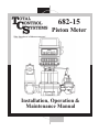
682-15
Piston Meter
Catalog Subtitle
Installation, Operation &
Maintenance Manual
Page 2
Table of Contents
Safety Warning Symbols
Receipt & Inspection
Notice
Meter Overview
Meter Specifications
Meter Types
Material of Construction
System Recommendations
System Recommendations (Continued)
System Recommendations (Continued)
System Recommendations (Continued)
Start Up Recommendations
Start Up Recommendations (Continued)
Meter Calibration
Meter Calibration (Continued)
Meter Calibration (Continued)
Calibration Adjustment
Maintenance
Maintenance (Continued)
Storage Instructions
Dimensions
Meter Assembly
Meter Assembly (Continued)
2
3
3
4
5
5
6
6
7
8
9
10
11
11
12
13
14
15
16
16
17
18
19
Air Eliminator & Strainer Assembly
Air Eliminator & Strainer Assembly (Continued)
Hydraulic Preset Valve Assembly
Hydraulic Preset Valve Assembly (Continued)
Torque Specifications
Meter Body Repair
Meter Bonnet Repair
Compensator Shaft Repair
Drive Shaft Repair
Plunger Cup Replacement
Air Eliminator Repair
Air Eliminator Repair (Continued)
Hydraulic Valve
Hydraulic Valve (Continued)
Meter Trouble Shooting
Air Eliminator Trouble Shooting
Hydraulic Preset Valve Trouble Shooting
Material Safety Data Sheet
MSDS (Continued)
MSDS (Continued)
MSDS (Continued)
Notes
Notes
Warranty
20
21
22
23
24
25
26
27
28
29
30
31
32
33
34
35
36
37
38
39
40
41
42
43
Warning Symbols
CAUTION
Follow the warning instructions within the following information to avoid equipment failure,
personal injury or death.
TURN POWER OFF
Before performing any maintenance, be sure to
turn system power off to avoid any potential
electric spark.
FLAMMABLE
Flammable liquids and their vapors may cause a
fire or explosion if ignited.
EYE PROTECTION
Pressurized systems may cause hazardous leaks
and spray that may be dangerous for your eyes.
Always wear eye protection around pressurized
systems and its hazardous liquids.
INJURY
Wear gloves for protection from hazardous liquids that may cause irritation or burns.
READ
Read and understand all related manuals thoroughly. The Engineering and OIM manuals will
provide the knowledge for all systems, maintenance and operation procedures. If you have any
questions, please consult the factory.
Page 3
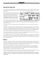
Receipt & Inspection
Upon receipt of meter shipment, be sure to inspect the packaging and the flow meter assembly for any damage before signing the receipt of the shipment. Notify the delivery company about possible damage and refuse receipt of
the shipment.
Flow Meter Identification Plate
Meters are individually boxed and are protected
with packing material. Each package is identified
with the flow meter assembly part number, description, direction of flow and serial number.
Verify the meter model is the correct model, size,
and configuration as ordered. Contact your distributor if there is any discrepancy or question.
Meter assemblies should be handled with appropriate methods for the awkwardness of size and weight involved. Appropriate clothing and shoes need to be utilized. Transport the meter package to the installation site with appropriate transportation methods, careful not to
damage the flow meter.
Be careful of any loose or protruding staples from the packaging, as they can be very sharp and may potentially
cause injury.
If foam has been used to protect meter, carefully remove top foam layer before attempting to remove meter assembly from box. Foam packaging maybe formed around the meter assembly making it difficult to remove. If meter is
bolted upon a wood pallet remove bolts while being careful not to let the meter tip over when the support has been
removed. Do not lift the meter assembly by flex hoses, thermowells, wires, pulsers, or put objects through meter.
Removing meter assembly from packaging without adhering these warnings may cause serious injury.
The wooden pallets and bases meet the ISPM 15; Guidelines for Regulating Wood Packaging Material in International Trade through the Timber Products Inspection Company (TP #2134).
Every effort has been made to remove the calibration fluid before shipment. All TCS flow meters are plugged and
foam packed flow meters are enclosed in a plastic bag. A Material Safety Data Sheet (MSDS) can be reviewed on
PAGE 37. Appropriate precautions should be taken regarding any personal, environmental and material compatibility with the end use system.
Notice
Total Control Systems (TCS) shall not be liable for technical or editorial errors in this manual or omissions from
this manual. TCS makes no warranties, express or implied, including the implied warranties of merchantability and
fitness for a particular purpose with respect to this manual and, in no event, shall TCS be liable for special or consequential damages including, but not limited to, loss of production, loss of profits, etc.
The contents of this publication are presented for informational purposes only, and while every effort has been
made to ensure their accuracy, they are not to be construed as warranties or guarantees, expressed or implied, regarding the products or services described herein or their use or applicability. We reserve the right to modify or
improve the designs or specifications of such products at any time.
TCS does not assume responsibility for the selection, use or maintenance of any product. Responsibility for proper
selection, use and maintenance of any TCS product remains solely with the purchaser and end-user.
All rights reserved. No part of this work may be reproduced or copied in any form or by any means – graphic,
electronic or mechanical – without first receiving the written permission of Total Control Systems, Fort Wayne,
Indiana USA.
Page 4
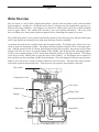
Meter Overview
The 682 meter is a true Positive Displacement Meter, with the inlet and outlet on the same horizontal
plain (straight in - straight out). Within the meter, three (3) plungers are fitted within their respective cylindrical measuring chambers. The plungers are joined to a wobble plate, which has a shaft extending
from its upper surface. The wobble plate also has a valve pivot attached beneath it. The valve pivot
drives a sliding valve from piston to piston as product flows, controlling the sequence of events.
The wobble plate shaft is always held at an inclined position by the center gear post, and the wobble plate
itself is prevented from rotating by four guide pins on the pivot bracket assembly.
As product enters the meter, it initially flows into the upper housing. The sliding valve will now be in position to open one measuring cylinder. The plunger for that particular cylinder will be at the upper position. With the pressure below it relieved, and an upper housing full of product, the pressure on top of that
plunger will cause it to move toward the bottom of the cylinder, thus forcing out the remaining product.
As this occurs, another plunger will be forced from the down position to the upper position. The sliding
valve moves via the wobble plate to open the inlet of this cylinder. As the plunger moves upward, it
draws product into the measuring cylinder from the bottom. Once this plunger reaches the upper position,
and the cycle will repeat, so long as product continues to enter the meter. If product flow stops, pressure
in the meter equalizes and motion stops. Thus the meter only operates when product is flowing.
Drive Shaft
Counter Drive Gear
Valve Pivot
Wobble Place
Sliding Valve
Plunger
Measuring Chamber
Inlet Flow
Outlet Flow
Page 5
Meter Specifications
Flange Connection:
1-1/2” NPT Flange Connection, 1” and 2” NPT Flange. Optional
BSPT, Slip Weld or ANSI flanges available upon request.
Flow Rate:
0.2 to 50 GPM
(0.76 to 189 LPM)
Maximum Pressure:
150 PSI
(10.5 BAR)
Working Temperature:
-20 F to 160 F
(-28.9 C to 71 C)
Meter Types
SP - Standard Petroleum
For metering refined petroleum products such as Fuel Oils, Gasoline, Diesel, Bio-Diesel, Motor Oils, Kerosene, Vegetable Oils, Ethylene Glycol, Naptha, etc.
SPA - Standard Petroleum (Aviation)
For metering refined petroleum products such as Aviation Gasoline, Fuel Oils, Jet Fuels, Gasoline, Diesel,
Bio-Diesel, Kerosene, etc.
SPD - Standard Petroleum (Ductile Iron)
For metering refined petroleum products such as Leaded and Unleaded Gasoline, Fuel Oils, Diesel, BioDiesel, Aviation Gasoline, Ethanol Blends, Methanol Blends, Kerosene, Vegetable Oils, Motor Oils,
Ethylene Glycol (Antifreeze), etc.
AF - All Ferrous
For metering Pesticides, Nitrogen Solutions, Fertilizer, Chlorinated Solvents and Paints, Inks, Alcohols,
Adhesives, Motor Oils, Molasses, Liquid Feeds, etc.
SS - Stainless Steel
For metering the same liquids as the SP, SPA, SPD and AF flow meters, but includes food processing and
special handling fluids such as Nitric, Phosphorus and Glacial Acetic Acids, Anti-Icing Fluids, Vinegar,
Fruit Juices, etc.
SSD - Stainless Steel (Diesel Exhaust Fluid)
For metering Diesel Exhaust Fluid (DEF), AdBlue, ARLA and AUS32
Page 6
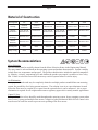
Material of Construction
Description
SP
SPA
SPD
AF
SS
SSD
Housing
Anodized
Aluminum
Anodized
Aluminum
Ductile Iron
Ductile Iron
Stainless Steel
Stainless Steel
Internal
Mechanism
Iron, Steel &
Stainless Steel
Ni-Resist II
Iron, Steel &
Stainless Steel
Iron, Steel &
Stainless Steel
Stainless Steel
Stainless Steel
Ball
Bearings
Stainless Steel
Stainless Steel
Stainless Steel
Stainless Steel
Ceramic
Ceramic
Internal
Hardware
Stainless Steel
Stainless Steel
Stainless Steel
Stainless Steel
Stainless Steel
Stainless Steel
Packing Seal
FKM
FKM
Simriz®
Simriz®
Simriz®
EPDM
Body O-ring
FKM
FKM
PTFE
PTFE
PTFE
EPDM
Simriz® is a registered trademark of Freudenberg-NOK.
System Recommendations
Meter Selection
The flow meter must be carefully chosen from the Meter Selection factors in the Engineering Manual.
The meter must be selected based on the operating system and product characteristics. System variables
include flow rate, temperature and pressure. The product characteristics include the material compatibility, lubricity, viscosity, suspensions, pH, and whether the product can congeal, crystallize or leave a dry
film. Failure to select the correct flow meter may result in system failure or serious injury.
Air Elimination
In any system that the tank may be completely drained or multiple products manifold into one metering
system, the possibility of air being present increases. The solution is an air or vapor eliminator located
before the flow meter to vent the air or vapor from the system before it can be measured. Air or vapor
elimination is required for all weights and measures regulatory approvals in custody transfer applications.
Control Valves
Safety and isolation valves should be used throughout the metering system. In any pumping system where
there is one (1) pump and multiple flow meters, a digital or hydro-mechanical Rate-of-Flow control valve
must be used at each flow meter to prevent over speeding of the flow meters.
Page 7
System Recommendations (Continued)
Best Plumbing Configuration
1). Flow meter must have secure mounting to a riser or foundation
2). The inlet and outlet piping must be securely supported, in a manner of not to allow pipe stress on flow
meter.
3). System should be designed to keep the flow meter full of liquid at all times.
4). System piping should have full 1-1/2” pipe diameter throughout the metering system to allow for
minimal pressure loss.
5). The pipe should be laid out as straight as possible to reduce pressure loss from flow restriction.
6). The meter and piping must be installed in such a way as to avoid accidental draining of the meter.
Meter inlet and outlet should be lower than the associated system plumbing (sump position).
7). It is not necessary for the air eliminator to be installed directly bolted to the meter. It can be installed
upstream from the meter. For effective operation of the air eliminator, it should be mounted between
the meter and any valves, tees or any other potential places where air may enter the system.
8). The metering system should include a means for calibration.
Protection From Debris
On new installations, care must be taken to protect the meter from damage during start-up. It is recommended to put a strainer before the meter. Damage may result from the passage through the meter of dirt,
sand, welding slag or spatter, thread cuttings, rust, etc. The insertion of a spool (a flanged length of pipe
equal in length to the meter and accessories attached to the meter) in place of the meter until the system is
flushed, temporarily bypassing the plumbing around the meter, will also protect the meter from debris.
Once the system has run “clean” for a period of time the meter may be reinstalled or protective devices
removed.
Thermal Expansion
As with most liquids, they will expand and contract with temperature. In any system where there is a
chance for liquid to be captured between closed valves without relief, thermal expansion will likely occur
and create dangerously high pressures within the system. Care should be taken in designing the system in
which thermal shock may occur by implementing Pressure Relief Valves or Thermal Expansion Joints in
the system design.
When product is trapped within the system, the pressure will increase by 126 PSI (8.69 BAR) for every
one (1) temperature degree increase.
Page 8
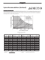
System Recommendations (Continued)
Viscosity VS. Pressure Loss
The product viscosity will have a direct relationship on the flow rate of the system. The following chart is the flow meter limitation in relation to the flow rate and pressure loss, based on product viscosity. If the system flow rate and viscosity do not
meet your requirements, please select a flow meter from our range of 700 series rotary flow meters that have the capability to
handle higher flow rates with a lower pressure loss.
Viscosity Conversion Chart
(Specific Gravity = 1)
SSU
Saybolt
Universal
31
34
38
47
60
80
100
130
160
210
260
320
370
430
480
530
580
690
790
900
CPS
Centipoise
1
2
4
7
10
15
20
25
30
40
50
60
70
80
90
100
120
140
160
180
CPS
Centipoise
200
220
240
260
280
300
320
340
360
380
400
420
440
460
480
500
550
600
700
800
SSU
Saybolt
Universal
1,000
1,100
1,200
1,280
1,380
1,475
1,530
1,630
1,730
1,850
1,950
2,050
2,160
2,270
2,380
2,480
2,660
2,900
3,380
3,880
CPS
Centipoise
900
1,000
1,200
1,300
1,400
1,500
1,700
1,800
1,900
2,000
2,200
2,400
2,500
3,000
3,500
4,000
5,000
5,500
6,000
6,500
SSU
Saybolt
Universal
4,300
4,600
5,620
6,100
6,480
7,000
8,000
8,500
9,000
9,400
10,300
11,200
11,600
14,500
16,500
18,500
23,500
26,000
28,000
30,000
CPS
Centipoise
7,000
8,000
8,500
9,000
9,500
10,000
15,000
20,000
30,000
40,000
50,000
60,000
70,000
80,000
90,000
100,000
125,000
150,000
175,000
200,000
Centipoise
Centistokes
=
Centipoise = Centistokes x Specific Gravity
Specific Gravity
SSU
Saybolt
Universal
32,500
37,000
39,500
41,080
43,000
46,500
69,400
92,500
138,500
185,000
231,000
277,500
323,500
370,000
415,500
462,000
578,000
694,000
810,000
925,000
Page 9
System Recommendations (Continued)
Hydraulic Shock (Water Hammer)
Hydraulic shock is a rise in pressure, which happens when an operating system has immediate change in
direction of flow such as a fast valve closure at a high operating flow rate. Hydraulic shock can damage
any item in the way of the product flow such as internal parts of the meter, valves, and pump. System design and improper operating procedures will elevate this problem. The use of 2-stage preset control
valves or surge suppressing bladders or risers will help reduce or eliminate this problem.
To compute the shock pressure when a valve is closed quickly (recommended to be less than 6 PSI):
Shock Pressure (PSI) = 63 x Velocity (FPS)
In order to eliminate hydraulic shock, you need to slow down the valve closure rate. The time required to
close the valve so that the line pressure will not exceed the normal pressure at no flow is:
Time (seconds) = 0.027 x L x V
N–F
V
L
N
F
=
=
=
=
Velocity in Feet/Seconds
Length of pipe before the valve in feet
Line pressure at no flow
Line pressure at full flow
Products that Dry/Congeal/Crystallize
There are many liquids that crystallize, harden and/or solidify on contact with air or with an increase in
temperature. A proper system design and a good understanding of the product being measured will help
to avoid the possibility of air entering into the system and the product being affected.
Calibration
The meter shall be tested and calibrated with the product it is intended to measure when installed. Total
Control Systems shall not be responsible for loss of product or any damages resulting from the end user’s
failure to test this meter to insure proper calibration. Every 682 series meter is tested and calibrated at the
factory to prove it is calibratable in your system. It is the owner’s responsibility to report this device to
the local Weights and Measures officials for their inspection before the meter is put to use.
Page 10
Start up Recommendations
¡WARNING!
Test equipment should be grounded to prevent a possible spark. Test area should have no ignition source. Operators should
wear personal protection and prevent any product exposure and environmental issues.
Start-up instruction for new installations or after maintenance and repairs:
1). Only properly trained personal should design, install, or operate metering system.
2). Remove plastic threaded plugs placed in meter for shipping protection. They are not to be used in
meter system because of the PVC plugs low rated pressure, compatibility, and sealing issues.
3). Place the meter in an area with ample workspace, secure from vibration, and pipe line stress. Mount
and bolt down on to a fixed stand or platform. This prevents meter stress, which will cause leakage
and metal fatigue.
4). Apply thread sealing compound and gasket materials that are compatible with product.
5). Do not weld to meter or accessories. This will weaken housings and cause o-ring and casting leaks.
6). Always wear personal safety protection equipment such as goggles, steel toed shoes, gloves and full
body clothing.
7). Be sure to install a pressure relief valve or expansion joint in the system to protect against thermal
expansion.
8). Make sure all system components are properly secured and tightened.
9). All meter assembly bolts and connections are tight.
10). Air eliminator vapor release is properly vented and piped into a reservoir container or back to the
supply tank.
11). Electrical connections are properly installed and start/stop switches are off and locked-out.
12). Flooded suction to the Pump. Fluid is available to system and will not starve or cavitate pump.
13). Slow flooding of system
Start up system with all shut off valves in the closed position. When a pump is turned on and a
valve opened in a new, dry system, tremendous liquid and air pressure can be built up in the piping
and forced through the meter. The high pressure and volume of air causes the meter to operate more
quickly than normal. When product reaches the meter, there is an abrupt slowing of the meter
pistons, which could cause damage to the register, piston arms, plunger cups, main pivot bracket
assembly, drive gear and other internal components. The recommended method of starting any
system is to flood the piping gradually. This allows product to slowly force the air from the entire
system.
Page 11
Start-Up Recommendations (CONTINUED)
14). When operating the meter with accessories, valves should be opened slowly to avoid a pressure
surge that can damage the meter or air eliminator. System pressures should be maintained below
70 PSI (4.9 BAR).
15). Custody transfer metering systems must be calibrated by a regulatory agency before product can
be sold off the meter. Contact your local authorities for proper calibration.
16). Strainers should be cleaned frequently or have a maintenance schedule. This will ensure a clean
system and long service life.
Meter Calibration
The method of proving should be selected, and necessary provisions made, during the design stage of the
installation. Of the most common used systems, portable provers have the advantage of more closely reproducing the condition under which the product is normally delivered.
Use Accurate Prover
Scientifically designed provers are commercially available for proving meters, and no other kind should
be used. Even scientifically designed provers should be checked periodically for accuracy. Weights and
Measures officials have been very cooperative in giving assistance to checking privately owned volumetric provers.
Recommended size of test measure:
The prover capacity should be equal to at least one minute’s flow through the meter at its maximum rate.
These provers are not merely truck compartments or drums, but are scientifically designed test measures,
having proper drainage means built into them, a calibration gauge glass neck, and protection against deformation (which causes volume changes).
A “homemade” prover, whether a drum or a tank is not likely to be satisfactory, and may cause expensive
errors due to inaccurate meter calibration.
Setting a Prover
The prover should be set level, using the levels provided on the prover, or separate ones. This insures consistent results when moving the prover from meter to meter.
Page 12
Meter Calibration (Continued)
Where to Test a Meter
The best place to test is in its normal operating position, instead of a test stand. In this way, the correctness of the installation and of the operation conditions will be verified by the test. Always test a meter
with the same liquid it is to measure, because a difference in viscosity, temperature and system plumbing
slightly affects meter accuracy.
Discharge Line from Meter
Where a portable prover is used, the liquid is generally discharged in to the prover in the same manner, as
a normal delivery would be made. Where a special test connection is used, the discharge line must be arranged to drain to the same point on each test. The meter flow rate and off/on is controlled at the end of
the discharge line.
Wetting the Prover
Reset the meter register to zero, and fill the prover to the zero or 100% marking of the scale. Disregard
the meter reading. Drain the prover, and reset the register. The reason for disregarding the first meter
reading is that the prover must be wetted, as its calibrated capacity is determined on its wet measure capacity by its manufacturer, and because the prover will be wet for the subsequent tests to be run.
After the prover has drained, allow a definitive time of a few minutes for drainage from the sides of the
tank. Total drainage time should be the same between all tests to insure uniform results. If a considerable
length of time is to elapse between tests, the wetting operation can be eliminated by allowing the prover to
remain full until the next test is to be run.
Making the Tests
The setup is now ready for accuracy the test. Reset the register to zero, and run the required test through
the meter. Do not exceed the maximum recommended rate of flow for the meter. Maximum and minimum
recommended rates of flow are marked on the 682 flow meter’s identification plate and maintenance manuals.
Determining Test Results
Run the meter to the mark on the indicator corresponding to the prover capacity, and read the over or under delivery in cubic inches or percent on the calibrated plate on the neck of the prover. If the plate is calibrated in cubic inches, the percentage error can readily be computed on the following basis:
(a) One gallon equals 231 cu.in.
(b) A 100-gallon prover holds 23,100 cu.in. Therefore, 23.1 cu.in. represents 0.1% error.
Page 13
Meter Calibration (Continued)
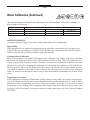
The National Institute of Standards and Technology, in its NIST Handbook 44 specifies a tolerance of
plus or minus the following:
Indication of Device
Wholesale
Vehicle
Acceptance Test
0.2%
0.15%
Tolerance
Maintenance Test
0.3%
0.3%
Special Test
0.5%
0.45%
METER TOLERANCE
Acceptance tolerances apply to new meters and repaired meters after reconditioning.
Repeatability
When multiple tests are conducted at approximately the same flow rate and draft size, the range of test
results for the flow rate shall not exceed 40% of the absolute value of the maintenance/normal tolerance
and the results of each test shall be within the applicable tolerance.
Changing Meter Calibration
Refer to meter literature for method of changing meter calibration. Any change in the meter calibration
adjustment will change the delivery in the same amount for all rates of flow. That is, the calibration curve
retains its shape, but is moved up or down. Therefore, if a meter tests satisfactorily at full flow, but drops
off too much at low flow, changing the calibration will not remedy this condition; it will bring the low
flow test to 100%, but it will also bring the full flow above 100% by the same amount that the low flow
was raised. A condition of this kind is caused either by the metering system, need for meter cleaning or
repairs, or because of an attempt to retain accuracy below the minimum recommended rate of flow for the
meter.
Temperature Correction
If the conditions of testing are such that there will be a change of more than a few degrees in the temperature of the liquids between the time it passes through the meter and the time the prover is read, it will be
advisable to make a temperature correction to the prover readings. To do this, it is necessary to install
thermowells; to take readings of the temperature of the liquids in the meter and in the prover; and to take
the degrees API of the liquid. Corrections can then be easily made by the use of the National Standard
API Tables.
Page 14
Calibration Adjustment
A.
It is important to test the repeatability and accuracy of your meter. To test repeatability:
1) Run a fast (high gallons per minute) test in your prover and record how much the meter is over or
under registering. Do NOT change the meter's calibration.
2) Run a slow (low gallons per minute) test and again record how much the meter is over or under
registration.
If the results from the fast and the slow test are the same or close to the same, the meter can be successfully calibrated. If the test results differ beyond the rated tolerance of the meter, then repairs are necessary
before the meter can be calibrated.
B.
C.
D.
E.
F.
G.
H.
I.
J.
K.
L.
M.
A valve or nozzle must be at the end of the delivery hose (at the prover).
Turn on the pump and purge the system of air. Leave the pump on.
Shut off the valve at the end of the delivery hose and let the system pressurize.
Wet the prover and empty it, letting it drip for 30 seconds.
Reset the register on the meter to "0".
Fill the prover to the line marked "0".
Record what the register reads. Every1/10 gallon difference between the register and the 5 gallons
known to be in the prover equals a +/- 2% inaccuracy. For example, a reading of 4.9 gallons on
the register, compared with a 5 gallon prover filled to the "0" line means the meter is giving away
2% of the product it meters.
The top disc on the calibrator has a tab sticking up. The tab is marked with a "plus" and a "minus"
sign. This indicates "plus" product and "minus" product. By turning the disc in one direction or
the other, product delivery will be increased or decreased.
A full revolution of the disc will change the calibration of the meter 3%. Therefore, if the meter
shows 4.9 gallons on the register, the disc should be turned 2/3 of one revolution (2%) in the minus direction, since in this case we want less product through the meter (5 gallons passed through
it in the test, and only registered 4.9 gallons).
Empty the prover and let it drip for 30 seconds.
Run a second test and make a fine adjustment; and then another test to check your fine adjustment.
Replace the pin into the disc, and seal it with the seal wire.
NOTE: If your meter has a mechanical or electronic preset, it should be set high enough so that it doesn't
affect the calibration process. Only a valve at the prover should be used to control the flow during calibration.
Page 15
Maintenance
¡WARNING!
Test equipment should be grounded to prevent a possible spark. Test area should have no ignition source. Operators should
wear personal protection and prevent any product exposure and environmental issues.
1).
Keeping accurate maintenance and calibration records can be an excellent tool in determining the
frequency of inspection or maintenance for a system. As the meter wears, the calibration will be affected and require adjustment. A personality profile can be created for each meter to help guide in a
maintenance schedule.
2).
Great care should be utilized in the maintenance of the metering system. Personal safety protection,
environmental hazards, and government regulations need to be the foremost priority. Only fully
trained personnel should be involved in maintenance. Failure to use original TCS replacement parts
will void any Weights & Measures approvals and risk damage to the meter system.
3).
ALWAYS RELIEVE INTERNAL SYSTEM PRESSURE TO ZERO BEFORE DISASSEMBLY
OR INSPECTION.
4).
SERIOUS INJURY OR DEATH FROM FIRE OR EXPLOSION COULD RESULT FROM
MAINTENANCE OF AN IMPROPERLY DEPRESSURIZED AND EVACUATED SYSTEM.
5).
Total Control Systems flow meters and accessories are often used with petroleum, solvents, chemicals, and other liquids that may be explosive, extremely flammable, very toxic, oxidizing, and corrosive. Severe injury or fatalities may arise if appropriate safety precautions are not followed.
6).
Before replacing or cleaning filter/strainer screen, the electrical system must be turned off. Product
needs to be drained from system. Collect all product and return to storage or dispose of properly.
Replace all drain plugs that were removed. Personal safety protection must be warn at this time.
Make sure there is adequate ventilation in the area. The metering system will not completely drain
so make sure you collect extra product when you remove the strainer cover. Clean the screen once a
week, or more often if there is a lot of sediment in the system. Make sure there is no ignition source
and the system is grounded. Replace all plugs that were removed for drainage.
7).
The metering system is heavy and awkward so take precaution to handle it properly.
8).
When inspecting the spring loaded preset valves do not place anything inside the housing, as the
action of the valve will pinch this object when the valve closes.
Page 16
Maintenance (CONTINUED)
¡WARNING!
Test equipment should be grounded to prevent a possible spark. Test area should have no ignition source. Operators should
wear personal protection and prevent any product exposure and environmental issues.
9).
When removing gaskets or o-rings, carefully check for damage or corrosion. Any cracked, rough,
worn, elongated or swollen o-rings need to be replaced. When replacing the o-rings, place grease
along the inside of the o-ring groove or completely around the o-ring to help the o-ring stay in the
o-ring groove during assembly. If o-ring is pinched or not in the o-ring groove, the meter system
will leak and cause serious problems to the environment and equipment. Collect all replaced parts
and dispose of properly. Do not weld any part of the meter system or accessories as this will
weaken the part and allow for leaks
10). All bolts and screws need to be coated with Anti-Seize lubricant. Then follow the torque
specifications for each flow meter, air eliminator, strainer or preset valve bolt on page 24.
11). Recommended levels of maintenance and inspection will depend upon the system variables, such as
the products being measured, their corrosiveness, system pressure requirements, government or
company regulations, and age of metering system. If hydrostatic testing is required, the system pres
sure should not exceed 1.5 times the marked meter pressure. It is not recommended to pneumatically
test the meter system at anytime.
12). If any component of the meter system is removed from the system, it should be thoroughly flushed
with a compatible liquid. After this is done, immediately refill the meter or accessory with a
compatible liquid to prevent corrosion and water build up.
Storage Instructions
Short periods of non-use of the meter (a week or less) should present no problem, provided that the meter
remains full of product. For long periods of non-use, such as winter storage, the following procedure is
recommended. Before long-term storage, a good practice is calibration of the meter to determine that it is
functioning properly.
1).
To store the meter when it is left in line, flush the system with clean water until 70-80 gallons of
water have gone through the meter.
2). Pump a 50% anti-freeze / 50% water solution through the entire system (100% RV antifreeze may
be used instead). With the pump running, shut off a valve downstream from the meter, making
sure that anti-freeze solution is present at that point. Then close an upstream valve, such that the
meter remains full of anti-freeze solution.
3). Remove the register from the meter, and lubricate the drive coupling shaft. After lubrication,
reassemble the register onto the meter.
When starting the system after a period of storage, check the meter's calibration as detailed earlier in the
service manual.
Page 17
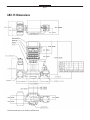
682-15 Dimensions
All measurements are in inches (millimeters)
Page 18
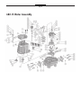
682-15 Meter Assembly
Page 19
682-15 Meter Assembly
Item
1
Description
Screw, 3/8-16 x 1-1/8
Qty
2
SP
297-050361
SPA
297-050361
SPD
297-050361
AF
297-050361
SS
1-126333
SSD
1-126333
1-126334
2
Washer, 3/8 Split Lock
2
15-050641
15-050641
15-050641
15-050641
1-126334
3
Counter Support
1
680050
680050
1-312518
1-312518
1-312518
680050
4
Roll Pin
1
3-130752
3-130752
3-130752
3-130752
3-130752
3-130752
5
Drive Shaft
1
1-126900
1-126900
1-126900
1-126900
1-126900
1-126900
6
Screw, 10-24 x 1/2
6
1-128279
1-128279
1-128279
1-128279
1-128279
1-128279
7
Washer, #10 Split Lock
12
1-126316
1-126316
1-126316
1-126316
1-126316
1-126316
8
Compression Washer
2
1-130872
1-130872
1-130872
1-130872
2-130872
2-130872
9
Drive Shaft Packing Kit
1
226199-1
226199-1
226199-1
226199-1
226199-1
680699-2
10
Washer, 9/16 OD x 0.10 T
5
1-126903
1-126903
1-126903
1-126903
1-126903
1-126903
11
Pipe Plug, 1/4''
2
1-126146
1-126146
1-126146
1-126146
2-126146
2-126146
12
Cover & Post Assembly
1
680250
680250
680253
680253
680252
P680155
13
O-Ring
1
680210
680210
680212
680212
680212
680810
14
Washer, 3/4 OD x 0.015 Rulon
1
1-125120
1-125120
1-125120
1-125120
1-125120
1-125120
15
Counter Drive Gear Assembly
1
226136-1
226136-1
226136-1
226136-1
226136-2
226136-1
16A
Cotter Pin, 1/16 x 1/2
2
-
-
-
-
1-126318
1-126318
16B
Retaining Ring, 0.320 ID x 0.025 T
1
12-053420
12-053420
12-053420
12-053420
-
-
17
Washer, 7/8 OD x 0.15 Rulon
1
1-125407
1-125407
1-125407
1-125407
1-125407
1-125407
18
Drive Shaft Gear
1
226135-1
226135-1
226135-1
226135-1
226135-2
226135-1
19
Cotter Pin, 3/16 x 1-1/4
1
13-052870
13-052870
13-052870
13-052870
1-126319
13-052870
20
Drive Shaft Pin 1/4 x 1-3/32
1
1-126913
1-126913
1-126913
1-126913
1-126914
1-126913
21
Cotter Pin, 1/16 x 1/2
1
1-126318
1-126318
1-126318
1-126318
1-126318
1-126318
22
Seal Wire and Seal
1
1-118849
1-118849
1-118849
1-118849
1-118849
1-118849
23
Seal Pin
1
1-019602
1-019602
1-019602
1-019602
1-126929
1-126929
24
Compensator Shaft
1
1-224081
1-224081
1-224081
1-224081
1-224119
1-224119
25
Nut, 5/15-18
1
2-050301
2-050301
2-050301
2-050301
1-126320
1-126320
26
Compensating Washer
1
1-126927
1-126927
1-126927
1-126927
1-126927
1-126927
27
Index Disc
1
1-126931
1-126931
1-126931
2-126931
1-126931
1-126931
28
Index Plate
1
1-226085
1-226085
1-226085
1-226085
1-130853
1-130853
29
Compression Spring
1
1-130935
1-130935
1-130935
1-130935
1-130935
1-130935
30
Compensator Shaft Seal Kit
1
227000-1
227000-1
227000-1
227000-1
227000-1
680700-2
31A
Screw, 7/16-14 x 1-1/4
7
600054
600054
700054
700054
700054
700054
31B
Drilled Screw, 7/16-14 x 1-1/4
2
600054D
600054D
700054D
700054D
700054D
700054D
32
Flange Washers
1
702018
702018
702018
702018
702018
702018
33
Bearing Retainer, Plunger
3
1-126957
1-126957
1-126957
1-126957
1-126957
1-126957
34
Plunger Screw, 10-32 x 3/8
12
1-126329
1-126329
1-126329
1-126329
1-126329
1-126329
35
Bearing Seat, Plunger
3
1-219378
1-219378
1-219378
1-219378
1-130908
1-130908
36
Piston Connector, Plunger
3
1-126939
1-126939
1-126939
1-126939
1-126939
P1-126939
37
Plunger Disc
3
1-126878
1-126878
1-126878
1-126878
1-126878
P1-126878
38
Plunger Cup Kit (3 Cups)
1
218769-1
218769-1
218769-1
218769-1
218769-1
218769-1
39
Plunger Cup Support
3
1-126876
1-126876
1-126876
1-126876
1-126876
P1-126876
40
Plunger Assembly
3
226182-9
226182-2
226182-9
226182-2
226182-2
219407-6
41
Nut, 1/4-20
3
1-126321
1-126321
1-126321
1-126321
1-126321
1-126321
42
Washer, 1/4 Split Lock
6
1-126317
1-126317
1-126317
1-126317
1-126317
1-126317
43
Slack Roller Assembly
1
219800-1
219800-1
219800-1
219800-1
219800-2
680051
44
Washer, 0.863 OD x 0.030 Rulon
1
1-125103
1-125103
1-125103
1-125103
1-125104
1-125104
45
Slack Spring Assembly
1
898 221403-1
221403-2
898 221403-1
221403-2
221403-5
221403-5
46
Ball, 1/4 Dia.
3
1-124588
1-124588
1-124588
1-124588
2-130905
2-130905
47
Wobble Plate Assembly
1
219331-1
219331-2
219331-1
219331-1
219901-2
219901P
48
Wear Plate
1
1-217934
1-217934
1-217934
1-217934
-
-
49
Ball, 5/8 Dia.
1
1-125046
1-125046
1-125046
1-125046
1-130905
1-130905
50
Main Pivot Assembly
1
219572-4
219572-4
219572-4
219572-4
219572-4
219572-4
51
Compensating Pinion
1
1-129607
1-129607
1-129607
1-129607
1-129607
1-129607
52
Screw, 1/4-20 x 3/4
3
1-126327
1-126327
1-126327
1-126327
1-126327
1-126327
53
Main Pivot Bracket Assembly
1
218236-4
218236-2
218236-4
218236-4
219260-6
219260P
54
Slotted Screw, 1/4-20 x 1
3
1-126962
1-126962
1-126962
1-126962
1-126962
1-126962
55
Screw, 1/4-20 x 1
6
1-126326
1-126326
1-126326
1-126326
1-126326
1-126326
56
Bracket
1
3-218608
3-218608
3-218608
3-218608
6-218608
P6-218608
57
Valve
1
1-219330
1-219330
1-219330
1-219330
220496-2
220496-2
58
Seat
1
1-038618
1-038622
1-038618
1-038618
1-310336
P310336
59
Seat Gasket
1
-
-
-
1-038619
1-038619
1-038619
60
680128P
Body, Seat, and Pin Assembly
1
680125
680122
680124
680126
680118
61A
Flange Bolts
4
702017
702017
702017
702017
702017
702037
61B
Drilled Flange Bolts
4
702017D
702017D
702017D
702017D
702017D
702037D
62A
Flange; 1-1/2” NPT
2
701600
701600
701601
701601
701602
701602P
62B
Flange; 1-1/2” BSPT
2
701603
701603
701621
701621
701812
701812P
Flange O-ring
2
702012
702012
702013
702013
702013
702812
63
Page 20
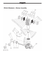
740 Air Eliminator / Strainer Assembly
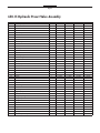
Page 21
740-20 Air Eliminator / Strainer Assembly
740-20
Item
Description
Qty
SP
SPD
IP
AF
SS
SSD
1A
Cap Screw
8
740050
740050
740050
740050
740050
740050
1B
Drilled Cap Screw
4
740050D
740050D
740050D
740050D
740050D
740050D
Ring Washer
12
740051
740051
740051
740051
740051
740051
3A
Outlet Cover; NPT
2
740010
740016
740010
740016
740018
P740018
3B
Outlet Cover; BSPT
2
740710
740716
740710
740716
740718
P740718
4
Encapsulated Valve Plate
2
740205
740215
740215
740215
740215
740205
5
Screw
4
740030
740030
740030
740030
740030
740030
6
Split Lock Washer
2
740017
740017
740017
740017
740017
740017
7A
Cap Screw
2
700054
700054
700054
700054
700054
700054
7B
Drilled Cap Screw
2
700054D
700054D
700054D
700054D
700054D
700054D
8
Flat Washer
4
702018
702018
702018
702018
702018
702018
9
Air Eliminator Housing
1
740020
740022
740020
740022
740024
P740024
10
Plug
1
2-126146
2-126146
2-126146
2-126146
2-126146
2-126146
11
Retaining Clip
2
740012
740012
740012
740012
740012
740012
12
PTFE Reed Strip
2
-
740077
740077
740077
740077
740077
13
Float Assembly
1
740013
740013
740013
740013
740013
740013
14
Diffuser and Shaft Assembly
1
740035
740035
740035
740035
740035
740035
15
Top Seal O-ring
1
740009
740019
740019
740019
740019
740809
16
Strainer Housing
1
742021
742022
742021
742022
742023
P742023
17A
0.050 Strainer Basket, STD
1
-
-
742005
742005
742005
-
17B
40M Strainer Basket, STD
1
742010
742010
-
-
-
P742010
17C
80M Strainer Basket
1
742015
742015
-
-
-
-
17D
100M Strainer Basket
1
742025
742025
-
-
-
-
18
Seal Ring
1
742003
742004
742004
742004
742004
742803
19
Basket Cover
1
742050
742052
742050
742052
742053
P742053
20
Basket Cover; Two 1/2” NPT Ports
1
742055
742056
742055
742056
742057
-
21
3/8” x 1/2” NPT Thermowell
1
740305
740405
740305
740405
740405
-
22
Strainer Cover, Optional
1
740041
740042
740041
740042
740042
-
23
Reed Valve
2
740007
740007
740007
740007
740007
740007
24
Plate Seal
4
740005
740004
740004
740004
740004
-
25
Valve Plate
2
740038
740006
740006
740006
740006
-
26
Valve Plate Kit
2
740138
740106
740106
740106
740106
-
27
1/2” x 1/2” NPT Thermowell
1
740300
740400
740300
740400
740400
-
28
Flange O-ring
1
702012
702013
702012
702013
702013
702812
29
Basket Cover; One 1/2” NPT Port
1
742155
742156
742155
742156
742157
-
2
Page 22
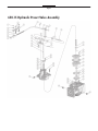
650-15 Hydraulic Preset Valve Assembly
Page 23
650-15 Hydraulic Preset Valve Assembly
Qty
SP
AF
SS
SSD
Retaining Ring
1
6-052482
6-052482
6-052482
6-052482
2
Washer, Flat
1
65034
65034
65034
65034
3
Spacer
2
1-130852
1-130852
1-130852
1-130852
4
Preset Bracket
1
1-226102
1-226102
1-226102
1-226102
5
Washer, Split Lock
2
ZPW 1/4LW
ZPW 1/4LW
ZPW 1/4LW
ZPW 1/4LW
6
Screw
2
68004
68004
68004
68004
7
Locknut
2
65008
65008
65008
65008
8
Swivel Block
1
1-128140
1-128140
1-128140
1-128140
Item
1
Description
9
Connecting Link
1
65025
65025
65025
65025
10
Cotter Pin
4
1-126318
1-126318
1-126318
1-126318
11
Washer
2
1-126903
1-126903
1-126903
1-126903
12
Actuating Arm
1
65016
65016
65016
65016
13
Lifter
1
65010
65010
65010
65010
14
Valve Handle Shaft
1
65005
65005
65005
65005
15
Retaining Ring
2
65026
65026
65026
65026
16
Shaft Bearing
2
65004
65004
65004
65004
17
Bracket
1
65012
65012
65012
65012
18
Screw, 1/4-20 x 1/2
3
65032
65032
65032
65032
19
Washer, Split Lock
3
1-126317
1-126317
1-126317
1-126317
20
Valve Stem
1
65018
65018
65018
65018
21
Roll Pin, 5/32 x 1
1
65027
65027
65027
65027
22
Screw, 10-24 x 1/2
11
1-128279
1-128279
1-128279
1-128279
23
Washer
3
1-126316
1-126316
1-126316
1-126316
24
Compression Washer
1
1-130872
1-130872
1-130872
1-130872
25
Spacer
1
1-130893
1-130893
1-130893
1-130893
26A
Screw, 5/16-18 x 1
2
65033
65033
65033
65033
26B
Drilled Screw, 5/16-18 x 1
2
65033D
65033D
65033D
65033D
27
Seal
2
2-126898
2-126898
2-126898
2-126898
28
Seal O-Ring
2
5-311554
5-311554
5-311554
650803
29
Cover
1
650015
65031-2
65031-4
P65031-4
30
Pipe Plug
3
2-051913
2-051913
2-126146
2-126146
31
Poppet Spring
1
65007
65007
65007
65007
32
Washer, Flat
2
65035
65035
65035
65035
33
Plunger Cup Support
1
65014
65014
65014
65014
34
Plunger Cup
1
65013
65013
65013
65013
35
Plunger
1
65030
65030
65030
65030
36
Valve Disc
1
65009
65009
65009
65019
37
Valve Seat
1
65006
65006
65006
65006
38
Poppet Guide
1
65029
65029
65029
65029
39
Gasket
1
65021
65021
65021
65022
40
O-Ring
1
65001
65001
65001
65002
41
Valve Body Assembly
1
650127
650227
650327
P650427
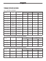
Page 24
TORQUE SPECIFICATIONS
682-15 METER ASSEMBLY
Foot Lbs.
Part Number
Tool
Newton Meter
Bolt/Nut Size
Unlubricated
Lubricated
Unlubricated
Lubricated
TCS 3-23095
/8” hex
wrench/socket
7
/16-14 UNC
50
37.5
67.8
50
TCS 1-130876
/8” hex
wrench/socket
7
/16-14 UNC
27
20
36.6
27
TCS 297-050361
9
/16” hex
wrench/socket
3
/8-16 UNC
30
22.5
40.6
30
TCS 1-126353
9
/16” hex
wrench/socket
3
/8-16 UNC
19.7
11.8
26.7
16
TCS 1-128279
slotted
screwdriver
10-24 UNC
1.9
1.1
2.6
1.5
TCS5-230958
¾” hex
wrench/socket
½-13 UNC
43.1
25.9
58.4
35.1
TCS 1-126329
slotted
screwdriver
10-32 UNF
1.9
1.1
2.6
1.5
TCS 1-126321
/16” hex
wrench/socket
¼-20 NUT
6.3
3.8
8.5
5.2
TCS 1-126327
slotted
screwdriver
¼-20 UNC
6.3
3.8
8.5
5.2
TCS 1-126326
7
/16” hex
wrench/socket
¼-20 UNC
6.3
3.8
8.5
5.2
5
5
7
650-15 HYDRAULIC PRESET VALVE ASSEMBLY
Foot Lbs.
Part Number
Tool
Newton Meter
Bolt/Nut Size
Unlubricated
Lubricated
Unlubricated
Lubricated
/16-18 UNC
11
6.6
14.9
8.9
TCS 65033
½” hex
wrench/socket
TCS 65032
7
/16” hex
wrench/socket
¼-20 UNC
6.3
3.8
8.5
5.2
TCS 1-126279
slotted
screwdriver
10-24 UNC
1.9
1.1
2.6
1.5
5
740-20 AIR ELIMINATOR/STRAINER ASSEMBLY
Foot Lbs.
Part Number
Tool
Newton Meter
Bolt/Nut Size
Unlubricated
Lubricated
Unlubricated
Lubricated
TCS 740050
1/2” hex screw
wrench/socket
5/16-18 UNC 2B
11
6.6
14.9
8.9
TCS 701017
9/16” hex screw
wrench/socket
3/8-16 UNC 2B
19.7
11.8
26.7
16.0
TCS 740030
slotted
screwdriver
8-32 UNC 2B
1.65
1.0
2.2
1.4
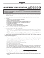
Page 25
682 METER BODY REPAIR INSTRUCTIONS
¡WARNING!
All internal pressure must be relieved to ZERO (0) pressure before beginning disassembly
of meter or components
I. A. Remove all parts and seals from the meter body and clean them. You may air blast parts with a glass bead
material to clean parts.
B. Always replace bracket (#56), screws (#54) & (#34), plunger cups (#38) and Rulon seals (#14, 17 & 44).
C. Check for:
1. Excessive wear on the wobble plate (#47) guide holes.
2. Pitting on ball bearings (#49) & (#46).
3. Excessive wear on the guide posts on main pivot bracket assembly (#53).
4. Wear on the SP/SPA/SPD/AF valve (#57) or SS/SSD valve insert (#57).
5. Wear on the valve seat (#58).
6. Wrinkles on the sleeves in cylinders of the body.
NOTE: Honing sleeves with Emory wheel may buff out wrinkles.
II. A. Mount valve seat (#58) to body (#60), with seat gasket (#59).
B. Lap valve (#57) for SP, SPA, SPD, AF, SS or SSD.
1. SP, SPA, SPD, & AF – Use Rectorseal® Clover lapping compound or equivalent on valve (#57) & seat
(#58). Move valve repeatedly in a Figure 8, and clean compound off valve and seat thoroughly when finished.
2. SS/SSD – Use 220 & 320 grit silicon sand paper to lap valve & insert (#57). Move valve repeatedly in a
Figure 8 on 220 grit paper, then use the 320 grit paper. Wipe valve Rulon insert clean.
C. Replace plunger cups (#38) in piston (#40) and carefully place into cylinders. SEE PLUNGER CUP KIT for
piston repair instructions on page 29.
D. Main Pivot & Wobble Plate Assembly.
1. Screw the main pivot assembly (#50) all the way into main pivot bracket assembly (#53) and place pinion
(#51) in its slot. For AF/SP/SPA/SPD meters, unscrew the pinion and main pivot bracket assembly 5 full
turns. For SS/SSD meters, unscrew the pinion and main pivot bracket assembly 3 ½ full turns. This
should help bring meter within range while calibrating.
2. Drop the slotted screws (#54) into bracket.
3. Place bracket with screws into main pivot bracket assembly.
4. Set 5/8” ball bearing (#49) into position.
5. Place the wear plate (#48) over the screws (#54).
6. Set wobble plate (#47) onto the screws (#54) and fasten down with lock nuts (#41) & lock washers (#42).
7. Set slack spring assembly (#45) on wobble plate post, then the Rulon washer (#44) & slack roller (#43).
8. Mount main pivot bracket assembly to valve (#57) & seat (#58) with lock washers (#42) & screws (#52).
E. Connect Pistons to Wobble Plate.
1. Slide piston plunger assembly into each cylinder, careful not to cut or crimp the plunger cup.
2. Carefully slide connector (#36) over the wobble plate (#47) bearing seats.
3. Place 1/2” ball bearing (#46) onto wobble plate and cover with bearing seat (#35) & retainer
(#33).Tighten bearing seat (#33) with lock washers (#7) and screws (#34).
4. Rotate wobble plate (#47) & pistons (#40) through each cylinder to make sure of smooth flowing characteristics.
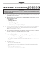
Page 26
682 METER BONNET REPAIR INSTRUCTIONS
¡WARNING!
All internal pressure must be relieved to ZERO (0) pressure before beginning disassembly
of meter or components
I.
A. Remove all parts and seals from the meter bonnet and clean them. You may air blast parts with
a glass bead material to clean parts.
B.
Check for excessive wear or corrosion. NOTE: Problems with any of these following items will
require a new bonnet or shafts.
1. Drive Shaft (#5).
2. Compensator Shaft (#24).
3. Bonnet (#12)
a. Drive shaft packing surface.
b. Compensator shaft surface.
c. Counter drive gear assembly seat (#15) & post.
II. A. Insert drive shaft gear assembly (#18) with Rulon washer (#17) into the meter drive shaft packing. Install drive shaft packing Kit (#9). SEE DRIVE SHAFT PACKING KIT INSTRUCTIONS for more information on page 28.
B.
Slide the counter drive gear assembly (#15) with Rulon washer (#14) over the post. Each meter
uses about 3-4 washers (#10) before the cotter pin (#21) is inserted.
C.
Compensator Shaft Assembly
1. Insert AF/SP/SPA/SPD retaining ring (#16B) or SS/SSD cotter pin (#16A) on to the compensator shaft (#24).
2. Insert compensator shaft into packing gland.
3. Install compensator shaft packing kit (#30).
SEE COMPENSATOR SHAFT PACKING KIT INSTRUCTIONS for more information on
page 27.
D. Mount Bonnet to Base.
1. Place oring (#13) into housing (#60).
2. Move compensator shaft (#24) to match pinion (#51) in the base by using the index disc
(#27).
3. Mount bonnet (#12) to base (#60).
4. Insert screws (#31) and washers (#32), then tighten.
Page 27
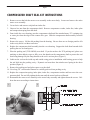
COMPENSATOR SHAFT SEAL KIT INSTRUCTIONS
1. Remove screws that bolt the meter cover assembly to the meter body. Loosen and remove the entire
meter cover assembly.
2. Cut seal wire and remove seal pin from index disc.
3. Unscrew hex nut from the compensator shaft. Remove compensator washer, index disc, index plate
and compression spring from the shaft.
4. From inside the cover housing, turn the compensator shaft until the attached truarc "E" retaining ring
or cotter pin clears the edge of the counter drive gear. Slide the compensator shaft assembly from the
housing.
5. Remove the spacer. Lift the old packing from the housing. Be sure there are no foreign particles left
in the cavity and it is without corrosion.
6. Replace the compensator shaft assembly into the cover housing. Support the shaft from beneath while
packing the new seal and spacer.
7. Place the packing tool (TCS 600200) over shaft. If you do not have the TCS packing tool, please use
masking or other adhesive tape to fully cover the threads on the compensator shaft to protect the seal
from being damaged by the sharp threads as the seal is set into place (Figure 1).
8. Lubricate the seal on the inside up and outside oring prior to installation with bearing grease to help
the seal slide into the packing cavity. Dynamic seal must have the stainless steel spring in the down
position (Figure 2).
9. Remove the packing tool and place spacer over the shaft.
10. Use a long 3/8” socket and a hammer to carefully push seal into packing cavity.
11. Replace the compression spring, index plate, index disc, compensator washer and hex nut to the compensator shaft. Do not fully tighten the hex nut until the meter has been calibrated.
12. Reassemble the meter cover assembly to the meter body assembly and tighten down the screws. Calibrate the meter according to instructions.
1
2
Page 28
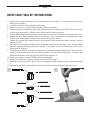
DRIVE SHAFT SEAL KIT INSTRUCTIONS
1. Remove screws that bolt the meter cover assembly to the meter body. Loosen and remove the entire
meter cover assembly.
2. Carefully remove the roll pin from the drive shaft.
3. Remove (3) screws, (3) lock washers, and the compression washer.
4. From inside the cover housing, remove the cotter pin from the counter drive shaft. Remove the counter drive gear and washers. Slide the drive shaft assembly from the housing.
5. Lift the old packing from the housing. Be sure there are no foreign particles or corrosion in the cavity.
6. Replace the drive shaft assembly into the cover housing. Secure in position by reassembling the counter drive gear with the Rulon washers and cotter pin previously removed.
7. Support the counter drive shaft assembly from beneath while packing the spacer bearings, washers
and the new seal.
8. Pack first spacer bearing with flat surface on top and push down into packing cavity. Rulon bearing
material is preassembled into each spacer bearing. Use caution so as to not damage the surface of the
Rulon material (Figure 1).
9. Lubricate the seal inside up and outer oring prior to installation using bearing grease. Place the packing tool (TCS 600100) over shaft to slide the dynamic seal into the packing cavity. Dynamic seal
must have the stainless steel spring in the down position (Figure 2).
10. Insert second spacer bearing with flat surface on the bottom.
11. Replace the compression washer with the screws and lock washers.
12. Insert the roll pin in the drive shaft. Be sure to support the shaft while doing this to prevent bending
it.
13. Reassemble the meter cover assembly to the meter body assembly and tighten down the screws.
1
2
Page 29
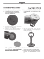
PLUNGER CUP REPLACEMENT
1)
2)
Remove plunger assembly from meter body.
Loosen and remove two (2) round head
screws and lift plunger cup support from
plunger cup and plunger disc.
3)
Discard the old plunger cup kit. Place the new
plunger cup on the plunger disc.
Add the cup support and secure with the two
(2) round head screws previously removed.
4)
NOTE: Apply Red Loctite 271 (or equivalent)
to the screw threads. Be sure the cup is evenly
spaced on the plunger disc and support.
5) Form the cup by turning the plunger assembly
in your hand using your thumb to roll the edge
slightly.
6) After the cup is partially formed, place the
plunger assembly into the meter body and press
into the piston cylinder.
7) Turn the assembly in the piston cylinder to assure the cup is evenly formed to the cylinder.
8) Replace previously removed parts and reassemble meter. Test and calibrate meter for accuracy.
Page 30
¡WARNING!
All internal pressure must be relieved to ZERO (0) pressure before beginning disassembly
of meter or components
1)
2)
3)
4)
5)
1)
Using a hex or socket wrench, remove the four screws and washers from the cover plate.
Remove the cover plate and o-ring from the housing.
Remove the strainer screen.
Check inside housing for any debris and remove using a clean cloth.
Clean strainer screen by rinsing with a liquid cleaning agent compatible to your product
application. A brush may be used to remove imbedded particles. If screen is too dirty to clean,
then replace the screen.
Wipe clean the face of the cover plate and seal ring. Check o-rings for damage and replace as
needed.
Reassembly of 720 Strainer Assembly
1)
2)
3)
Replace the strainer screen into the housing.
Place the end cover o-ring in the groove of the end cover.
Put the end cover with o-ring installed on the strainer housing.
Replace and fasten end cover with the 4 screws and washers. Tighten the screws according to the
torque chart.
Page 31
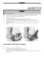
¡WARNING!
All internal pressure must be relieved to ZERO (0) pressure before beginning disassembly
of meter or components
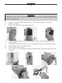
1)
2)
3)
Using a 1/2” wrench or socket, remove the cover screws from air eliminator cover plate.
Remove cover plate.
Remove valve plate, inspect and replace as needed.
1
1)
2)
3)
4)
5)
2
3
To remove the air eliminator assembly, remove the four screws and washers attaching it to the
strainer assembly.
Using a flathead screwdriver, remove the screws attaching reed valves to air eliminator housing.
Remove the two screws on the diffuser screen.
Slide out diffuser shaft assembly.
Remove the two screws attaching reed valve to the float assembly. Inspect and replace reed valves
as needed.
1
2
4
3
5
Page 32
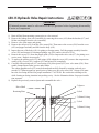
650-15 Hydraulic Valve Repair Instructions
¡WARNING!
All internal pressure must be relieved to ZERO (0) pressure before beginning disassembly
of meter or components
1) Drain all fluid from metering system prior to valve removal.
2) Remove the linkage from valve assembly by removing the screws (#18) from the bracket (#17) and
lift the arm linkage from the valve assembly.
3) Remove valve from meter and piping.
4) Remove the roll pin (#21) from the valve stem (#20). Then remove the screws (#26) from the cover
(#29) and poppet assembly and lift from the body (#41).
5) Inspect the seat of the body (#41) for pitting or foreign matter. Pull the poppet assembly from the
cover (#29) and inspect for a damaged plunger cup (#34) and/or valve disc (#36).
6) Remove the screws (21) from the poppet guide (#38) to inspect the valve seat (#37) for pitting or excessive wear. Replace as necessary.
7) To replace the packing seal (#27) and orings (#28) within the cover (#29), remove the compression
washer (#24), screws (#22), washers (#23) and stem (#20) completely.
8) Carefully slide packing seal (#27) and orings (#28), then spacer (#25) over valve stem (#20). Reassemble compression washer, screws and washers.
The carbon graphite seals (#27) must be heated and carefully formed by rotating each seal on a
smooth 3/8” diameter punch or pencil prior to fitting over the valve stem (#20). Orings (#28) must
have the slot facing the fluid for proper installation. CAUTION: Be certain not to damage seals
while forming or during insertion into packing cavity. See the illustration below for proper installation sequence.
9) Replace the previously removed parts and reassemble the valve.
Drive Shaft
Retaining Plate
5) Spacer
4) Seal
3) Slotted O-ring
2) Seal
1) Slotted O-ring
Page 33
650-15 Hydraulic Valve Repair Instructions
Page 34
Meter Trouble Shooting
A. PROBLEM: The meter allows product to pass through it, but the register on the meter doesn't move.
1) Check the reset knob on the register. On older style Veeder Root registers, this knob can become stuck-in, which will
disengage registration. In this case, though, the totalizer would still register.
2) Check the screws that hold the gear plate onto the bottom of the register. If they become loose, neither the register nor
the totalizer will register.
3) The drive-gear coupling shaft (in the gear plate under the register) is broken or pin missing.
4) The retaining ring on the counter drive gear has come off or broken, allowing the drive gear to disengage from the
drive shaft gear assembly.
5) The post on the wobble plate inside the meter has snapped off. When this happens, it usually indicates that air has
been pumped though the meter.
6) The connector on the piston assembly inside the meter is broken, allowing product to pass.
B. PROBLEM: The meter will not deliver product and will not register.
1) Check any air eliminator and/or strainer screens in the system for blockage. Also, check all valves in the system for
proper operation. If the problem still hasn't been discovered after those checks, determine what the pressure is before
and after the meter (with the pump running). Equal readings would indicate the meter isn't necessarily the problem.
2) On older style offset Tokheim 682 meters, there is a back pressure valve on the discharge of the meter, which can become stuck shut.
3) If it is determined that the problem is in the meter itself, then the meter valve (inside the meter) is stuck down onto the
valve seat.
C. PROBLEM: The meter delivers more product then what is registered.
1) First, the meter should be tested for repeatability. To test repeatability, run a fast (high gallons per minute) test in
your prover and record how much the meter is under registering. Do NOT change the meter's calibration. Then, run a
slow (low gallons per minute) test and again record the amount that the meter is under registering
2) If the results from the fast and the slow test are the same or close to the same, the meter has repeatability and can be
calibrated. If the test results differ beyond the rated tolerance of the meter, then repairs are necessary.
NOTE: If the meter is more than 7% inaccurate (register reading of 4.65 or less gallons in a 5 gallon test), then it cannot be calibrated until repairs are made.
D. PROBLEM: The meter delivers less product than what it registers.
1) The meter could have the wrong gear train in its register.
2) Check for leaks on the suction side of the pump, including the pump seal. Air, which is sucked into the system and
pushed though the meter would affect registration.
3) After eliminating these possible causes, check the meter's repeatability, as outlined in problem C above.
4) Register may need repair.
E. PROBLEM: The meter has excessive knocking noise.
1) Check the calibrator on the meter. If it is adjusted too far out, excessive knocking is possible.
2) If the problem isn't the calibrator, then the meter valve or another internal part may need repair or replacement.
Page 35
Air Eliminator Trouble Shooting
A. PROBLEM: Product is flowing from the Air Eliminators vents
1) Foreign matter located in between seal plate orings and metal reeds.
2) The seal plate oring may be worn through service life.
3) The seal plate oring may be cut or dislodged and requires replacement.
4) The float may have been punctured, containing liquid, not allowing the float to rise and seal the air
vents.
5) The float may have been ruptured from a surge of pressure within the system.
6) The metal reeds may be fatigued and requires replacement.
7) The metal reeds may be out of alignment with the seal plate.
B. PROBLEM: The meter is still registering air within the system
1) There can be numerous reasons why the meter may still register air. First look at the system configuration and see where air is being introduced into the system. Then determine if the meter is
registering “free air” or “entrained air”. Free Air is much easier to remove from the metering system and may require the use of the Spring Loaded Back Check Valve and/or the Differential Air
Check Valve to help the air eliminator operate more effectively. Entrained Air is much more difficult to remove. Typically the best way to eliminate Entrained Air will be to remove the air source
of entry into the system. Some examples are from cavitating pumps and leaking pump/valve seals.
See Air Elimination in the Service Manual for more information.
2) The air return line is not the required minimum of 1/2” ID.
3) The metering system has no sufficient way of eliminating the air to atmosphere. Example: Incorrectly installed “Catch Can” reservoir (lower than the air eliminator itself), or the reservoir is allowed to become full, incorrectly sized vent, etc…)
Page 36
Preset Valve Trouble Shooting
A. PROBLEM: The valve will not close completely.
1)
2)
3)
4)
The shaft of the piston may be bent from excessive force.
Debris may be between the plunger and poppet piston guide.
The plunger cup seal may be worn, cut or torn.
The Veeder Root preset may have a worn or bent trip mechanism that is not allowing the preset to
function correctly.
B. PROBLEM: The valve shuts immediately upon first stage trip, bypassing the second
stage closure.
1) The mechanical linkage might need to be adjusted, moving the Nylon locking nuts forward or
backwards to change the closing of the preset valve.
2) The Veeder Root preset may need to be “raked” or adjusted for the correct shut-off volume. See
Veeder Root 7889 preset service manual for further instructions, which may need to be downloaded from the www.veeder.com website.
3) The Veeder Root preset may have a worn or bent trip mechanism that is not allowing the preset to
function.
C. PROBLEM: The preset batch over or under registers correct volume.
A) The mechanical linkage might need to be adjusted, moving the Nylon locking nuts forward or
backwards to change the closing of the preset valve.
B) The Veeder Root preset may need to be “raked” or adjusted for the correct shut-off volume. See
Veeder Root 7889 preset service manual for further instructions.
C) The Veeder Root preset may have a worn or bent trip mechanism that is not allowing the preset to
function.
Page 37
Material Safety Data Sheet
24 HOUR EMERGENCY ASSISTANCE
(260) 833-3173
GENERAL MSDS ASSISTANCE
(260) 484-0301
CODE: RPS
==========================================================================================
HAZARD RATING>
LEAST-0 SLIGHT-1 MODERATE-2 HIGH-3 EXTREME-4
==========================================================================================
DR LUBRICANTS, INC.
4611 NEWAYGO ROAD, SUITE D
FORT WAYNE, IN 46808
DATE: 01/21/06
TELEPHONE NUMBER: (260 484-0301
==========================================================================================
SECTION I - PRODUCT IDENTIFICATION
==========================================================================================
PRODUCT:
RP 1039
==========================================================================================
SECTION II - COMPOSITION AND HAZARDOUS INFORMATION*
==========================================================================================
OCCUPATIONAL
WT. PERCENT
EXPOSURE LIMITS
CHEMICAL NAME
CAS NUMBER
IS LESS THAN
(TLV-TWA) (TLV-STEL)
——————————————————————————————————————————————————–PETROLEUM
64741-65-7
90.0
100MG/M3
HYDROCARBON
PETROLEUM
HYDROCARBON
64742-53-6
10.0
5MG/M3
*ITEMS NOT SHOWN ARE NOT LISTED IN THE OSHA - T.S.C.A. HAZARDOUS CHEMICALS LISTING.
==========================================================================================
SECTION III - PHYSICAL DATA
==========================================================================================
BOILING RANGE:
ODOR:
APPEARANCE
VOLATILE BY WEIGHT:
VOLATILE BY VOLUME:
NA
PETROLEUM ODOR
AMBER LIQUID
NA
NA
VAPOR DENSITY:
EVAPORATION RATE:
SOLUBILITY:
PRODUCT DENSITY:
NA
NA
INSOLUBLE
0.790
==========================================================================================
SECTION IV - FIRE AND EXPLOSION HAZARD DATA
==========================================================================================
FLAMMABILITY CLASSIFICATION:
DOT:
EXTINGUISHING MEDIA:
COMBUSTIBLE
FLASH POINT: 150 F
(CLEVELAND OPEN CUP)
COMBUSTIBLE LIQUID
CARBON DIOXIDE, DRY CHEMICAL, FOAM
LEL:
UEL:
NA
NA
Page 38
Material Safety Data Sheet (Continued)
PRODUCT: RP 1039
PAGE - 2
==========================================================================================
SECTION IV - FIRE AND EXPLOSION HAZARD DATA
==========================================================================================
UNUSUAL FIRE AND EXPLOSION HAZARDS : DO NOT DIRECT A SOLID STREAM OF WATER ONTO BURNING
PRODUCT. THIS MAY CAUSE SPREADING AND INCREASE THE FIRES INTENSITY. COMBUSTION MAY PRODUCE: OXIDES OF CARBON, AND INCOMPLETELY BURNED HYDROCARBONS IN THE FORM OF FUMES AND
SMOKE.
SPECIAL FIREFIGHTING PROCEDURES: WEAR A SELF-CONTAINED BREATHING APPARATUS WITH FULL
FACEPIECE.
==========================================================================================
SECTION V - HEALTH HAZARD DATA
==========================================================================================
EFFECTS OF OVER EXPOSURE: MAY CAUSE MILD EYE IRRITATION AND REDNESS. PROLONGED OR REPEATED EXPOSURE TO THE SKIN MAY RESULT IN LOSS OF NATURAL OILS ACCOMPANIED BY DRYNESS,
CRACKING AND DERMATITIS. INGESTION MAY RESULT IN NAUSEA, DIARRHEA AND GASTRO INTESTINAL
IRRITATION. OVEREXPOSURE TO MIST MAY CAUSE UPPER RESPIRATORY TRACT IRRITATION AND DIFFICULTY BREATHING.
MEDICAL CONDITIONS PRONE TO AGGRAVATION BY EXPOSURE: NONE KNOWN.
PRIMARY ROUTE(S) OF ENTRY: DERMAL INHALATION INGESTION.
EMERGENCY AND FIRST AID PROCEDURES: IN CASE OF EYE CONTACT, IMMEDIATELY FLUSH EYES WITH
CLEAN WATER FOR AT LEAST 15 MINUTES. IF EYE IRRITATION PERSISTS, CONTACT A PHYSICIAN. IN
CASE OF SKIN CONTACT, REMOVE ANY CONTAMINATED CLOTHING AND RINSE SKIN THOROUGHLY WITH
WATER FOR AT LEAST 15 MINUTES. IF SKIN IRRITATION PERSISTS, CONTACT A PHYSICIAN. IN CASE OF
OVEREXPOSURE TO MIST, REMOVE VICTIM TO FRESH AIR: IF BREATHING IS DIFFICULT ADMINISTER OXYGEN: AND CONTACT A PHYSICIAN IMMEDIATELY. IF PRODUCT IS INGESTED DO NOT INDUCE VOMITING:
CONTACT A PHYSICIAN.
==========================================================================================
SECTION VI - REACTIVITY DATA
==========================================================================================
STABILITY: THIS PRODUCT IS STABLE UNDER NORMAL STORAGE CONDITIONS.
HAZARDOUS POLYMERIZATION: WILL NOT OCCUR UNDER NORMAL CONDITIONS.
HAZARDOUS DECOMPOSITION PRODUCTS: THERMAL DECOMPOSITION MAY RESULT IN THE FORMATION
OF: OXIDES OF CARBON, AND INCOMPLETELY BURNED HYDROCARBONS IN THE FORM OF FUMES AND
SMOKE.
CONDITIONS TO AVOID: AVOID CONTACT WITH OPEN FLAME, STORE IN ROOM TEMPERATURE AREA.
Page 39
Material Safety Data Sheet (Continued)
PRODUCT: RP 1039
PAGE - 3
INCOMPATIBILITY: AVOID CONTACT WITH STRONG OXIDIZING AND REDUCING AGENTS AND STRONG
ALKLI.
==========================================================================================
SECTION VII - SPILL OR LEAK PROCEDURES
==========================================================================================
STEPS TO BE TAKEN IN CASE MATERIAL IS RELEASED OR SPILLED: FOR SMALL SPILLS: SOAK UP SPILL
WITH ABSORBENT MATERIAL. FOR LARGE SPILLS: DIKE SPILL AND PUMP INTO DRUMS FOR PROPER DISPOSAL.
WASTE DISPOSAL METHOD: DISPOSE OF IN ACCORDANCE WITH ALL LOCAL STATE AND FEDERAL REGULATIONS.
==========================================================================================
SECTION VIII - SAFE HANDLING AND USE INFORMATION
==========================================================================================
RESPIRATORY PROTECTION: NORMALLY NOT REQUIRED, HOWEVER, WHEN THE TLV IS EXCEEDED WEAR
THE APPROPRICATE MSHA/NIOSH APPROVED RESPIRATOR.
VENTILATION: PROVIDE ADEQUATE VENTILATION (SUCH AS MECHANICAL OR LOCAL) TO ASSURE TLV IS
NOT EXCEEDED.
PROTECTIVE GLOVES: NORMALLY NOT REQUIRED, HOWEVER, IF HANDS ARE FREQUENTLY IN FLUID
WEAR OIL AND CHEMICAL IMPERVIOUS GLOVES.
EYE PROTECTION: SAFETY GLASSES REQUIRED FOR NORMAL USAGE, WEAR CHEMICAL GOGGLES WHEN
EXCESSIVE SPLASHING MAY OCCUR.
OTHER PROTECTIVE EQUIPMENT: NORMALLY NOT REQUIRED, HOWEVER, WHERE REPEATED CONTACT
OCCURS, WEAR IMPERVIOUS CLOTHING AND BOOTS.
HYGIENIC PRACTICES: FOLLOW STANDARD INDUSTRIAL HYGIENE PRACTICES. LAUNDER ANY CONTAMINATED CLOTHING BEFORE RE-USE.
==========================================================================================
SECTION IX - SPECIAL PRECAUTIONS
==========================================================================================
PRECAUTIONS TO BE TAKEN IN HANDLING AND STORAGE: DO NOT STORE IN THE PRESENCE OF HEAT,
SPARKS, FLAME OR ANY OTHER SOURCES OF IGNITION. STORE AWAY FROM STRONG OXIDIZING AGENTS.
EMPTY DRUMS MAY CONTAIN PRODUCT RESIDUES. ALL SAFETY PRECAUTIONS TAKEN WHEN HANDLING
THIS PRODUCT SHOULD ALSO BE TAKEN WHEN HANDLING EMPTY DRUMS AND CONTAINERS.
OTHER PRECAUTIONS:
NONE
Page 40
Material Safety Data Sheet (Continued)
PRODUCT: RP 1039
PAGE - 4
==========================================================================================
SECTION X - HMIS/NFPA RATINGS
==========================================================================================
HMIS:HEALTH:1 FLAMMABILITY:2 REACTIVITY:0 PERSONAL PROTECTION:C
NFPA:HEALTH:1 FLAMMABILITY:2 REACTIVITY:0 SPECIFIC HAZARD:
==========================================================================================
SECTION XI - OTHER REGULATORY INFORMATION
==========================================================================================
DOT HAZARDOUS:
NATURAL DESCRIPTION:
==========================================================================================
THE INFORMATION CONTAINED HEREIN IS, TO THE BEST OF OUR KNOWLEDGE AND BELIEF, ACCURATE.
HOWEVER, SINCE THE CONDITIONS OF HANDLING AND USE ARE BEYOND OUR CONTROL, WE MAKE NO
GUARANTEE OF RESULTS, AND ASSUME NO LIABILITY FOR DAMAGES INCURRED BY USE OF THIS MATERIAL. IT IS THE RESPONSIBILITY OF THE USER TO COMPLY WITH ALL APPLICABLE FEDERAL, STATE AND
LOCAL LAWS AND REGULATIONS.
==========================================================================================
Page 41
Notes
Page 42
Notes
Page 43
Warranty Information
WARRANTY
New 682 piston meters manufactured by Total Control Systems, a division of Murray Equipment, Inc. ("TCS") with
which this warranty is enclosed, are warranted by TCS to the original purchaser only for a period of ten (10) years from
the date of shipment, to be free, under normal use and service, from defects in material and workmanship. TCS manufactured new equipment or components are warranted for a period of one (1) year from the date of shipment, under normal use and service. This warranty is extended only to the original purchaser. For defects occurring within the stated
warranty period, TCS will repair or replace, at TCS's option; provided that part or parts are returned to TCS transportation charges prepaid, and the TCS's examination discloses the parts or workmanship to have been defective upon delivery to the purchaser.
EXCLUSIONS
TCS’s ten (10) year warranty applies to meters only and does not apply to accessories such as valves and air eliminators. Parts and equipment not manufactured by TCS may be covered by separate warranties of their respective manufacturers. This warranty does not cover any parts or equipment not manufactured by TCS or related companies. This
warranty does not extend to any equipment that has been altered in any way, subjected to misuse, negligence, accident,
or if operated in any manner other than in accordance with TCS's operating instructions or have been operated under conditions more severe than, or otherwise exceeding those set forth in the specifications. General maintenance, calibration,
clean up and normal wear is excluded from this limited warranty.
CLAIM PROCEDURES
In order to obtain performance by TCS of its obligations under this warranty, the original purchaser must obtain a Return
Goods Authorization (RGA) number from TCS’s customer service department within 30 days of discovery of a purported breach of warranty, but not later than the expiration of the warranty period. Once authorization is received,
return the defective meter, piece of equipment, or component covered by this warranty, with transportation charges prepaid, to TCS with a written statement setting forth the nature of the defect and RGA number.
LIMITATIONS
THERE ARE NO OTHER WARRANTIES OF ANY KIND, EXPRESS OR IMPLIED. TCS SPECIFICALLY DISCLAIMS ANY WARRANTY OF MERCHANTABILITY OR OF FITNESS FOR ANY PARTICULAR PURPOSE.
TCS will determine if all parts or meter defect falls within the warranty guidelines and will repair or replace within
a reasonable time span. TCS is not responsible for any in or out bound freight. TCS's sole obligation that shall represent the buyer's sole and exclusive remedy shall be to repair or at TCS's option to replace any product or part determined
to be defective. In no event shall TCS be liable for any special, direct, indirect, incident, consequential or other damages
of similar nature, including without limitation, loss of profits, products, production time, or loss of expenses of any nature
incurred by the buyer or any third party. TCS has not authorized on its behalf any representation or warranties to be
made, nor any liability to be assumed except as expressly provided herein; there is no other express or implied warranty.
REPAIR WARRANTY
All repair work is warranted for (90) days from the date of shipment to customer. Some parts may be warranted for
longer periods by the Original Equipment Manufacturer.
DESIGN AND EQUIPMENT CHANGES
Any changes in design or improvements added shall not create any obligation to install or replace equipment previously sold or ordered.
TCS900020 REV. 2
2515 Charleston Place
Fort Wayne, IN 46808
Toll Free: (800) 348-4753
Phone: (260) 484-0382
Fax: (260) 484-9230
Email: [email protected]