1
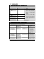
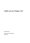
Cerebral State Monitor
Model CSM 2
User Manual
Danmeter A/S
Kildemosevej 13, DK-5000 Odense C, Denmark
Tel.:
+45 63 11 29 30
Fax:
+45 63 11 29 31
e-mail: [email protected]
www.danmeter.com
Rx only
Table of Contents
1
About this Manual .............................................................................................................................1
1.1
Device description ..................................................................................................................1
1.2
Indications for Use..................................................................................................................1
1.3
List of Symbols .......................................................................................................................2
2
Installation and Preparation..............................................................................................................2
3
Skin Preparation and Sensor Positioning..........................................................................................3
4
Description of the Device ..................................................................................................................4
4.1
General Overview ....................................................................................................................4
4.2
Keys and Controls Overview....................................................................................................5
4.3
Light Indicators.......................................................................................................................6
4.4
Description of Keys.................................................................................................................6
4.5
Operation Display Modes........................................................................................................7
4.6
Setup Menu.............................................................................................................................9
4.7
Settings.................................................................................................................................10
4.8
Events...................................................................................................................................11
4.9
CSM Parameters ...................................................................................................................12
5
Principle of Operation .....................................................................................................................14
5.1
High Quality Amplifier............................................................................................................14
5.2
Measurement Principle .........................................................................................................14
5.3
CSI Scale ...............................................................................................................................15
5.4
EMG ......................................................................................................................................16
5.5
Burst Suppression Indicator .................................................................................................16
5.6
Artifact and Noise Control.....................................................................................................16
6
CSM Battery / CSM Power Operation...............................................................................................17
6.1
Using CSM Power and CSM Rechargeable Batteries.............................................................17
7
Data Recording via CSM Link...........................................................................................................18
7
Data Recording via CSM Link...........................................................................................................19
7.1
CSM Link Software ................................................................................................................19
7.2
CSM Link ...............................................................................................................................19
8
Specifications ..................................................................................................................................21
9
Accessories .....................................................................................................................................22
10 Maintenance....................................................................................................................................22
11 Troubleshooting..............................................................................................................................24
12 System and Error Messages ...........................................................................................................26
13 Safety and Warranty ........................................................................................................................26
14 Service and Contacts.......................................................................................................................28
15 Technical description.......................................................................................................................30
This manual is published by Danmeter A/S, who reserves the right to improve and modify the
contents without prior notice. Modifications will, however, be published in future editions. All rights
reserved.
Cerebral State Monitor, CSM & CSI are trademarks of Danmeter A/S
Products manufactured by Danmeter A/S, Kildemosevej 13, DK-5000 Odense C, Denmark
US-English
PN 561105003-04
Declaration of Conformity:
Danmeter A/S hereby declares that the Cerebral State Monitor complies with the following
standards:
EN (IEC) 60601-1,
EN (IEC) 60601-1-2,
EN (IEC) 60601-2-26
UL 60601-1:2003
CAN/CSA-C22.2 No. 601.1-M90
CAN/CSA-C22.2 No. 601.1S1-94
CSA 601.1 Amendment 2:1998
CAN/CSA 601-2-26
1
About this Manual
This manual is intended to assist the user in operating the Cerebral State Monitor (CSM) in a safe
and effective manner.
This version of the manual was originally drafted, approved and supplied by Danmeter A/S in English.
Before operating the monitor read this manual thoroughly, with particular attention to all
warnings and cautions.
Note:
Although the monitor is built and tested to exacting specifications, it is not intended to
replace the supervision of level of consciousness monitoring by medical personnel. The user
should become thoroughly familiar with the features, operations, and accessories of the
monitor and exercise vigilance in its utilization.
WARNINGS
CAUTIONS
NOTES
1.1
are directions which, if not followed, could cause fatal or serious injury to an
operator, patient or any other person.
are directions which, if not followed, could cause damage to the equipment
described in this manual and/or any other equipment or goods, and/or cause
environmental pollution.
are intended to highlight unusual points as an aid to the operator.
Device description
The Cerebral State Monitor (CSM) is a non-invasive measurement tool for use by trained healthcare
professionals to measure the level of consciousness (LOC) in all areas of the hospital. Based on
EEG, an index (CSI) is calculated, which is used in the estimation of LOC. The CSM displays the CSI
but does not perform any data interpretation (i.e., all data interpretation is performed by a
physician).
1.2
Indications for Use
The monitor is intended for use in monitoring the hypnotic state of the brain by data acquisition of
EEG signals of the anesthetized or sedated patient in all areas of the hospital.
Caution:
Federal law (U.S.A.) restricts this device to sale, distribution, and use by or on the order of a
physician.
Cerebral State Monitor - CSM DFU
Page 1
1.3
List of Symbols
Type BF equipment
On / Off
Attention, consult accompanying documents
Do not dispose of in refuse collection. Dispose of at a recycling
station or equivalent in accordance with directive 2002-96-EC WEEE.
2
Installation and Preparation
The Cerebral State Monitor system CSM007 includes the following:
Cerebral State Monitor
CSM Wireless Link
Patient Cable
CSM Software CD
Rechargeable 9V Battery
User manual (this document)
Power Adapter (2 pieces)
Power Cable (2 pieces)
RS-232 Cable/USB Cable
Carrying case
Velcro strip 1.7x0.9”
Clip for patient cable
For replacement accessories, refer to chapter 9
Note
The performance of the CSM monitor by EEG acquisition, processing and calculation of the
CSM parameters and waveforms in the CSM monitor are ONLY guaranteed by the
manufacture when using the CSM Procedure Pack, part no. DMX005.
The possibility to use standard ECG electrodes is NOT RECOMMENDED
Cerebral State Monitor - CSM DFU
Page 2
3
Skin Preparation and Sensor Positioning
To ensure low sensor impedance, clean skin with mild soap and water is recommended as a skin
cleanser.
Note: Alcohol is not recommended as a skin cleanser; it leaves a film layer that may cause
high sensor impedance. If alcohol is used, ensure 30 second dry time.
The CSM Procedure Pack contains a skin preparation product and 3 neuro sensors.
Note: The performance of the CSM is only guaranteed by the manufacturer when the CSM
Procedure Pack is used.
Dry-abrade the skin gently using the skin prep product or with a dry wash cloth or gauze, to remove
the non-conductive skin layer. See diagram below.
Caution:
- Make sure no part of the sensors is in contact with any other conductive parts including
earth/ground.
- If skin rash or other unusual symptoms develop, remove sensors from patient.
- Change sensors every 24 hours to check skin integrity.
Position of the three sensors from your CSM Procedure Pack according the diagram below
Middle of forehead
Left side of forehead
Mastoid left side
Shown above is a left sided setup; right sided is also acceptable. Place sensors at the side farthest
from the surgical area.
The advanced signal processing of the monitor ensures that a deviation in the positioning of the
sensors up to 2 cm (0.78 in) has no significant influence on the index. However, it is recommended
to place the sensors on an area of the skull where only a few muscle fibers are present in order to
achieve the best quality signal.
Note: Once the sensors have been secured on the skin, attach the color-coded wires on the
patient cable to appropriate sensor.
Cerebral State Monitor - CSM DFU
Page 3
4
4.1
Description of the Device
General Overview
On/Off
+
Battery lid
Cerebral State Monitor - CSM DFU
CSM
Patient cable
power/charge connection
connection
Battery
compartment
Page 4
4.2
Keys and Controls Overview
2
RED Error
light
3
GREEN Power
adapter
Charge
Error
1
On/Off
5
Mute
key
4
Display
area
Set
Mute
7
Display
key
Display
Event
6
Set Event
key
8
Event Type
key
9
Control
key
Cerebral State Monitor - CSM DFU
Page 5
4.3
Light Indicators
2 RED Error light
Lights up when neuro sensor error situations are detected
3 Lights when power adapter is connected
4.4
Description of Keys
1 Power On
Press once
1 Power Off
Press and hold until “Power Off” bar disappears
1 Wireless Link connection, disconnection or reconnection
Press twice within 1 second
5 Mute key Mutes alarms
6 Set Event key / Set link
7 Display key
Changes between graphical and information screen
7a - For immediate impedance update. Press down firmly for one second
8 Event key
Select event type / Select link (accessory)
9 Control key
Used for menu selection of parameter settings
9a - Use the Control key to scroll in the menus or set values
9b - Select a submenu or function
9c - Go back one menu level
Cerebral State Monitor - CSM DFU
Page 6
4.5
Operation Display Modes
The CSM always starts with display A
Switch between display A, B, C, D and E by pressing the Display key (7).
Display Mode D
CSI trend histogram with 5-minute interval showing average, lowest and highest
CSI values within the interval. EMG% is displayed as a bar in the right panel
Display Mode C
Display Mode B
CSI trend curve with event markers and BS curve. EMG% is displayed as a bar in
the right panel. Operation time and numeric value of the actual CSI and BS%. The
time scale for the trend curve is 5.27 minutes and each tag is 60 seconds
Displays 3 seconds of EEG waveform. Use Event key (8) to scale up and down. EEG
scales are ±200μV, ±100μV (default), ±50μV, ±20μV and ±10μV
Display Mode A
10:12:05
0:47:11
Main information window with CSI, BS%, EMG%, SQI%, clock, operation time and
battery operation.
Display Mode E.
10:12:05
0:47:11
Sensor impedance, CSI, BS%, clock and operation time. When display E is active,
the sensor impedance is updated every 60 seconds. Press Display key (7a) firmly
for immediate impedance update
Cerebral State Monitor - CSM DFU
Page 7
The EEG waveform derives from the signal recorded between the frontal and mastoid electrodes. The
frequency content is 2-35 Hz. If the EEG amplitude is low then in some conditions the ECG might be
detectable in the EEG waveform
EMG% is shown in the display as a bar in the right-hand side. Operating time and numerical value for
current CSI and BS%. The time scale for the histogram graph is 180 min. The interval between each
tag is 60 min. The high-low bar in the current time interval (high-low bar to the far right) is updated
dynamically.
Special display features
CSI
BS%
EMG
SQI
Artifact
Sensor
alarm
---SQI value
-?-?-?-?-
Cerebral State Monitor - CSM DFU
Page 8
4.6
Setup Menu
General menu structure and menu selections
Top Menu
BS% 0
Menu
47 CSI
1
Alarm
Config
Device information
How to select menu settings from Display Mode
1. Remove battery lid.
2. From any Display Mode, press any arrow on the Control key (9).
3. The top menu appears.
4. Note: The last menu used is chosen.
How to set parameter values
1. Press the Control key (9a) to select menu.
2. Press the Control key (9b) to enter submenu.
3. Press the Control key (9a) to select parameter.
4. Press the Control key (9b) to highlight parameter value.
5. Press the Control key (9a) to select parameter value.
6. Press the Control key (9b) to accept setting or (9c) to cancel the selection and return
without any change.
7. Press the Control key (9c) to go back in one menu level steps.
If the Control key has not been activated in 20 sec. the CSM returns to Operation Display Mode and
stores the settings.
Note:
The change of settings will only be stored for future use after returning to Operation
Display Modes.
Cerebral State Monitor - CSM DFU
Page 9
4.7
Settings
Parameter
Menu
Description
Values (Default)
High Alarm
Alarm
Selects the CSI Alarm High Option
ON/OFF (OFF)
Low Alarm
Alarm
Selects the CSI Alarm Low Option
ON/OFF (OFF)
High Limit
Alarm
Selects the CSI High Alarm Level
2-99
(60)
Low Limit
Alarm
Selects the CSI Low Alarm Level
1-98
(40)
Language
Config
Selects device language
English
Contrast
Config
Selects display contrast
15-35
(20)
RF interface
Config
Select radio link active. If turned
OFF the link is completely inactive.
ON/OFF (ON)
Set clock
Config
Sets clock: Date Format, Year,
Month, Date, Hours, Minutes,
Seconds
Back light
Config
Sets display light and light
brightness
0 = Off
1 = Normal (1)
2 = Bright
AutoLNK
Config
Automatically establishes a
wireless link to any CSM link within
approx. 10 feet or to a specified
CSM link.
Inactive/Active/SN
(Inactive) SN is
only displayed if
link is established
The AutoLNK function
When AutoLNK is set to Inactive:
- active CSM Link(s) within range will pop-up in the Link display. Select the CSM Link serial
number you would like to connect to.
When AutoLNK is set to Active:
- active CSM Link within range will automatically be connected to CSM monitor
When AutoLNK is set to SN:
- CSM monitor automatically connects to the dedicated CSM Link if within range.
Cerebral State Monitor - CSM DFU
Page 10
Device Information:
Select submenu.
BS% 0
47 CSI
Device information
1
Info
Link
Log
Info:
Link:
Log:
4.8
•
•
•
•
Serial number.
SW version.
CSI version.
AD version.
•
•
- indicates no CSM Link connected.
If CSM Link connected the CSM Link serial number and software version will be shown.
•
•
•
Serial number.
#1 total no. of CSM sessions.
#2 total no. running hours.
Events
Pressing the Set Event key (6) results in a continuously numbered event with no description
displayed.
Pressing the Event Type key brings up the following selection menu:
BS% 0
47 CSI
Event types
1
Induction
Intubation
Maintenance
The following options event descriptions can be selected: Induction, Intubation, Maintenance,
Surgery, Injection, Note, End Maintenance and Movement.
When the desired option has been selected, press the Set Event key (6) to confirm. If no selection is
made within 5 seconds the system returns to the current Display Mode. Only the event numbers are
visible on Display Mode C. Event names will only be displayed when using the CSM Link option.
Events can be set with intervals of 3 seconds.
Cerebral State Monitor - CSM DFU
Page 11
4.9
CSM Parameters
BS% Indicator
The amount of Burst Suppression (very low-amplitude or “flat” EEG) is displayed in all Display Modes
at the top left hand side. Please refer to Section 5.5 for further information on the BS%
measurement.
EMG% and EMG bar
The EMG level is displayed either as a numerical percentage (0-100%) value in Display Mode A or
graphically as a bar at the right hand side in Display Mode B. Please refer to Section 5.4 for further
information on the EMG measurement.
Signal Quality Indicator (SQI%)
SQI% measures the quality of the acquired EEG signal. The calculation is based on the number of
artifacts during the last minute. The electrode-to-skin impedance is included in the SQI% calculation.
Higher electrode-to-skin impedances reduces the SQI%. Only electrode-to-skin impedances at 1 and
1 kΩ will result in a SQI% at 100. This quantity is displayed numerically as a percentage (0-100%,
100% equals best signal quality) in Display Mode A.
If the impedance of the white or black sensors exceeds 1kΩ, the SQI will fall gradually. Poor
impedance conditions may cause the SQI to fall to 50%.
Sensor Impedance
The impedance of the white and black sensors is continuously measured and displayed in Display
Mode E. Low sensor impedance values (typically between 1 and 3 kΩ) are essential for good
monitor operation. A “<1kΩ” readout means that sensor impedance is optimal.
Sensor Alarm
The Sensor Alarm signals the interruption of reliable CSI calculation due to corrupted or interrupted
EEG. This is usually caused by the use of diathermia or a faulty sensor connection (high sensor
impedance or disconnection of sensor leads). Should any of these situations occur, the Red Error
light (2) will turn on. The CSI is not calculated during these periods, but is replaced by -?-.
Alarms (High / Low)
Alarms can be set to signal the moment when the CSI rises above and/or falls below preset limits.
The High and Low Alarms can be turned on or off from the Alarm Menu, where the High and Low
Alarm limits can also be set. The High Alarm is ONLY activated when the current CSI has been lower
than the High Alarm value. This is convenient when the High Alarm is set in the awake patient. If High
Alarm is set to 60 and High Alarm ON, then the CSI must be lower than 60 once before the High
Alarm is activated. If the current CSI goes higher than 60 the CSM monitor alarm sounds.
Same functionality is present for Alarm Low.
Cerebral State Monitor - CSM DFU
Page 12
Battery Symbol
An icon labelled “BAT” in Display Mode A indicates the remaining battery capacity. For further
information on battery operation of the CSM, please see section 6.
Battery about 50-percent charged
Battery charging when icon animates
Battery fully charged (if not animated)
Note:
ONLY CSM Battery (CSMX04) will be charged in CSM Monitor
LINK Signal Symbol
An icon labelled “LNK” in Display Mode E indicates the state of the data transfer connection via the
CSM Link. For further information on the CSM Link feature, please see section 7.
Acoustic signals
Start-up
Event
Alarm (High/Low)
Low Battery
Cerebral State Monitor - CSM DFU
3 beeps
1 beep
2 beeps per sec. (Mute = mute 60 sec.)
2 beeps per sec. (Mute = mute 60 sec.)
Page 13
5
Principle of Operation
5.1
High Quality Amplifier
An instrumentation amplifier collects ongoing EEG with a high Common Mode Rejection Ratio
ensuring a high-quality EEG acquisition. Special artifact detection algorithms are used to eliminate
their effects on subsequent CSI calculations.
5.2
Measurement Principle
The performance of the CSM is based on the analysis of the frequency content of the EEG signal.
The energy of the EEG is evaluated in specific frequency bands. These are used to define two energy
ratios called alpha (α) and beta (β). Both of these show a shift in energy content from the higher to
the lower frequencies during anesthesia. The relationship between these quantities is also analysed
as a separate parameter (β-α).
α ratio = ln
E30 − 42.5 Hz
E6 −12 Hz
β ratio = ln
E30 − 42.5 Hz
E11− 21Hz
The monitor also on-line evaluates the amount of instantaneous burst suppression (BS) in each
thirty-second period of the EEG. This measurement quantifies the amount of “silent” or “flat” EEG
periods characteristic of the deepest levels of hypnosis.
These four parameters are used as input to a fuzzy logic classifier system that calculates the
Cerebral State Index.
EEG
αratio
βratio
β-α
BS%
Cerebral State Monitor - CSM DFU
FUZZY LOGIC
CLASSIFIER
CSI
Page 14
5.3
CSI Scale
The CSI is a unit-less scale from 0 to 100, where 0 indicates a flat EEG and 100 indicates EEG
activity corresponding to the awake state. The range of adequate anesthesia is designed to be
between 40 and 60. All values in the table are approximate values based on the mean values of the
patient behaviour.
The relationship among the CSI, the clinical state and the OAAS1 score is shown in the table below
CSI
Clinical State
OAAS
90 – 100
Awake
5
80 – 90
Drowsy
4
60 – 80
Light anesthesia or sedation
3
Range considered as adequate for
2-1
40 – 60
surgical anesthesia
Deep anesthesia, in most cases
1
10 – 40
accompanied by burst suppression
Close to coma, BS (burst suppression)
<1
0 – 10
larger than 75. When CSI is below 3,
the EEG is practically iso-electric.
The prediction probability (Pk) between the CSI and the OAAS was 0.92
The OAAS score correspond to:
OAAS
5
4
3
2
1
1
Clinical State
Responds readily to name spoken in normal tone
Lethargic response to name spoken in normal tone
Responds only after name called loudly and/or repeatedly
Does not respond to mild prodding or shaking
Does not respond to noxious stimulus
Observers Assessment of Alertness and Sedation
Cerebral State Monitor - CSM DFU
Page 15
5.4
EMG
High levels of facial muscular or electromyographic (EMG) activity can interfere with the CSI under
certain circumstances. The monitor incorporates an EMG filter that removes most of the potential
interfering EMG activity. The EMG bar shows the energy of the EMG level in the 75–85 Hz frequency
band (0–100 logarithmic). The bar is located on the right side of the display.
EMG activity is expected to be present when the patient is awake. When the patient is asleep, EMG
activity can increase due to:
•
•
•
•
Reflex reactions to painful stimuli during surgery.
Lack of muscular relaxation.
Muscular rigidity caused by some opioids (analgesics).
Presence of large external electrical fields, e.g. diathermy.
The EMG bar should be checked frequently, especially in case of a sudden increase in the CSI. If the
increase in CSI is accompanied by an increase in muscular activity, there is a risk that EMG is causing
interference. When this happens, attention must be paid to the stimuli received by the patient during
surgery. In the presence of hypnotically unrelated EMG, administration of a neuromuscular blocking
agent will cause the CSI to decrease. Since patients receiving neuromuscular blocking agents cannot
exhibit movement as a sign of arousal, the CSI is a valuable tool in their anesthetic management.
5.5
Burst Suppression Indicator
The monitor includes a Burst Suppression indicator to show periods when the EEG is iso-electric or
“flat”. The indication appears in the upper left-hand side of the graph window in the display and
shows the percentage of burst suppression over the last 30 seconds of the EEG signal. A BS% = 20
readouts means that the EEG has been iso-electric during 20% of the last 30 seconds.
5.6
Artifact and Noise Control
The artifact rejection algorithm ensures that the incoming EEG is not contaminated with noise. When
excessive noise is detected, the signal quality index is reduced reflecting the disturbance. The
artifact rejection algorithm will be active especially when diathermy and equipment creating external
interference is used.
Cerebral State Monitor - CSM DFU
Page 16
6
CSM Battery / CSM Power Operation
Using CSM Power and CSM Rechargeable Batteries
6.1
The CSM can be operated in two different modes
• Battery operated
• CSM Power operated
Warning:
Only standard CSM rechargeable battery CSMX04 or alkaline batteries must be used.
Battery operation (Alkaline batteries)
•
•
Always use new Alkaline batteries to ensure best results
Insert battery correctly
CSM Power operation and CSM rechargeable batteries
Warning:
Only for use with adapter CSMX05 (Ault Inc., Model MW117)
Note:
There is no alarm if the battery is not connected. If no battery is inserted, the monitor is switched off
when the external CSM Power is removed. There is no internal back-up battery in the monitor.
Note:
The clock is powered by an internal battery with a limited life (minimum 6 years from date of
manufacture). When the battery is used up, the clock will be reset, and the clock will blink on start
up. The monitor should then be sent for service.
Note:
To maintain and fully maximize the rechargeable battery lifetime, always connect the monitor to the
CSM Power when the device is not in use.
Battery Lifetime (Fully charged CSMX04 only at normal operation)
Wireless Link
Backlight level
Life time (hours)
OFF
OFF
10.5
OFF
1
9.0
OFF
2
7.0
ON
OFF
10.0
ON
1
8.5
ON
2
6.5
Cerebral State Monitor - CSM DFU
Note:
Using 9V alkaline disposable
batteries the battery life time
indicated in the table can be
multiplied by 2 to 3.
Page 17
CSM Power
Connect to power cable
Connect to CSM Power connection
1.
2.
3.
4.
5.
Insert the CSM rechargeable battery as indicated
Connect power cable to outlet and turn on power
Green indicator (3) lights up
Turn on monitor
When the CSM is connected to an electrical outlet, and turned on, the CSM can be
operated while the CSM battery is charged. If power is disconnected the CSM will continue
running on the CSM battery.
Electrical Operation Only
The CSM can be operated on mains with the CSM Power, with or without any type of approved
battery inserted.
7Note:
When CSM rechargeable battery (CSMX04) is used, it will charge automatically while the
electrical power is connected. ONLY CSM Battery (CSMX04) will be charged in the CSM
monitor.
Cerebral State Monitor - CSM DFU
Page 18
Data Recording via CSM Link
7.1
CSM Link Software
The real-time data capturing software for the Cerebral State Monitor makes it possible to record
online data wireless via the CSM Link. The following data is recorded:
• CSI
• BS
• EMG
• Sensor impedance
• SQI
• EEG
CSM automatically saves the last 18 hours of data and a maximum of 10 cases, independent of the
state of the wireless link (on or off)
7.2
CSM Link
Link status indicator
Power indicator
Connector for PC/Terminal
Connector power adapter
Description of CSM Link Indicators:
Power:
Link:
Power
Flashing:
Constant:
Cerebral State Monitor - CSM DFU
Link Selected
Link established
Page 19
Connecting CSM Monitor and CSM Link
1.
2.
3.
4.
5.
6.
7.
8.
Turn on the CSM Link.
Power indicator shows a constant light.
Link indicator is off.
Turn on the CSM monitor.
The CSM monitor shows a list of CSM Links found.
Select CSM Link ID (Serial No.) with the Event key (8) and the indicator Link flashes,
or choose skip in order not to establish a connection. (The radio is reactivated by
pressing the Power On key (1) twice or the next time the CSM is switched on.)
Accept the CSM Link by pressing the Set Event key (6).
When link has been established the indicator Link will show a constant light.
Disconnecting CSM Monitor and CSM Link
1.
2.
3.
Press Power On key twice within one second.
Highlight release using Event key (8).
Press Set Event key (6) to disconnect. CSM radio is inactive. (The radio is reactivated
by pressing the Power On key (1) twice or the next time the CSM is switched on.)
Connecting to CSM Link when the CSM radio is inactive
1.
2.
3.
4.
5.
6.
7.
8.
Turn on the CSM Link.
Power indicator shows a constant light.
LINK indicator is off.
Press Power On key twice within one second.
The CSM monitor shows a list of CSM Links found.
Select CSM Link ID (Serial No.) with the Event key (8) and the indicator Link flashes,
or choose skip in order not to establish a connection.
Accept the CSM Link by pressing the Set Event key (6).
When link has been established the indicator Link will show a constant
light.
Note:
If wireless has been active for more than five minutes without any connection to CSM-Link,
the radio is inactivated.
Cerebral State Monitor - CSM DFU
Page 20
8
Specifications
EEG sensitivity
Noise
CMRR
Input impedance
Sample rate
CSI and update
EMG
BS%
Digital output
Wireless range
Display size
Alarms
Artifact rejection
Sensor impedance range
Battery
Supply current
Max. battery lifetime - Alkaline
Max. battery lifetime –
Rechargeable
Recharge time
Weight
Dimensions
Classification
Sensors
Cable length
Mounting options
Memory
Environment – Operation
±400μV
< 2μVp-p, < 0.4μV RMS, 1–250 Hz
>140dB
>50Mohm
2000 samples/sec. (14 bits equivalent)
0-100. Filter 6-42 Hz, 1 sec. update
0-100 logarithmic. Filter 75-85 Hz, 1 sec. update
0-100%. Filter 2-42 Hz, 1 sec. update
Wireless to RS232 link or USB (ISM 2.4 GHz)
Up to 10 meters
1.3 x 0.7”
High / Low with user selectable limit
Automatic
0-10kOhm / measurement current 0,01μA
Rechargeable NiMH or 9V Alkaline
(6AM6/IEC:6LR61/ANSI:1604A )
30mA (typical)
30h (stand alone)
18h (transmitting wireless)
See table in section 6.1
4 Hours (CSMX04 only)
4.6 ounces (130 g) with battery
4.6x2.7x1.2”
Internal power supply/ Class II, type BF, continuous use
Danmeter Neuro Sensors
77” with 14” split
Velcro strip 1.7x0.9”
Data recording 18 hours
Temperature 50–104°F
Rel. humidity
30–75%
Air pressure
700–1060 hPa
Environment – Transport
Temperature 50–104°F *
and storage
Rel. humidity
30–95%
Air pressure
700–1060 hPa
* If transport without sensors: -4–158°F
Cerebral State Monitor - CSM DFU
Page 21
9
Accessories
CSMX04
CSMX05
CSMX06
CSMX09
CSMX10
CSMX11
CSMX12
CSMX19
CSMX18
CSMX13
DMX004
DMX013
DMX005
DMX007
CSMIUS
CSM rechargeable battery
CSM Power/Charger
Patient cable
Carrying case
Service manual, English
CSM Link Software
CSM Link RS232
CSM Link USB
CSM Link PHILIPS VOI
Velcro Strip (1.7x0.9”)
RS-232 cable
USB cable
CSM Procedure Pack
Clip for patient cable
User Manual
10 Maintenance
Routine Maintenance
To ensure the monitor remains in good operating condition, it is important to keep it clean and carry
out the routine maintenance procedures described below. There are no serviceable parts in this
instrument and all service is to be carried out by the manufacturer.
Note:
If the monitor is dropped, damaged or subjected to excessive moisture or high temperature, it
should immediately be taken out of service for examination by qualified service personnel.
Interval
As required
Every 12 months
Cerebral State Monitor - CSM DFU
Routine Maintenance Procedure
Clean the external surfaces of the monitor thoroughly before and
after a prolonged period of storage
1. Inspect power adapter plug and cable for damage.
2.Perform electrical safety checks (including leakage current
measurement)
Page 22
Cleaning
Clean the monitor periodically by wiping the outer case with a lint-free cloth lightly moistened with
warm water and a mild, non-abrasive cleaning solution or 70% isopropyl alcohol.
Note
The monitor case is resistant to the following cleaning solutions:
• Renu-klenz 16ml/L (Steris corp., USA)
• Vesphene Iise 8ml/L (Steris corp., USA)
• Warm water
• Isopropyl alcohol 99%
• Acetone 10%
• Hydrogen peroxide 3%
Same solutions can be used for cleaning the patient cable.
Storage
If the monitor is to be stored for a longer period, it should first be cleaned and the battery removed.
Store in a clean, dry atmosphere at room temperature and, if available, use the original packaging
for protection.
Fuses
Caution:
No user- replaceable fuses in the monitor or CSM power
Disposal
The monitor should be disposed of taking into consideration environmental factors, local laws and
regulations. All components can be safely disposed of in the approved manner as per hospital or
locally regulated guidelines.
Remove battery, if any, before disposal.
Test Routines
Refer to guide for biomeds.
Cerebral State Monitor - CSM DFU
Page 23
11 Troubleshooting
• CSM does not turn on when power key is pressed?
Change to a new battery or a fully recharged battery.
If changing the battery does not help, send the CSM for service.
• Rechargeable Battery seems to have a diminished user time
1. Turn on the monitor without patient cable and no CSM Power attached.
2. Wait until the monitor turns off (rechargeable battery discharged).
3. Connect CSM Power for minimum 4 hours to fully recharge.
• Sensor alarm – Red Error light turns on and CSI, BS and EMG replaced by -?Check all neuro sensors and their connections. This alarm can also be caused by
diathermy – see section 5.6.
Check the patient cable.
If not connected, then connect it.
If faulty, replace patient cable.
Check if either of the neuro sensors are disconnected or badly connected.
Replace faulty sensor
• Blanked index – but why?
Sensor impedance too high
If sensor impedance is >5kΩ the CSI, BS and EMG will be blanked (- - displayed).
Check that neuro sensors are not dry.
Check that the skin has been cleaned properly.
Clean and prep skin as described in section 3 and attach new neuro sensors.
Signal Quality Index (SQI) low
If the impedance of the white or black sensors exceeds 1kΩ, the SQI will fall gradually.
Poor impedance conditions may cause the SQI to fall to 50%.
Artifacts can have many causes: diathermy, EMG, etc. are typical causes.
If SQI falls because of extensive use of diathermy, it will rise as soon as the diathermy is
stopped.
Check that all neuro sensors and cable connections are correctly connected.
Has the use of any mechanical device that could generate high frequency activity (e.g.
patient warmer) been initiated or is any such device in close proximity to the CSM neuro
sensors?
If possible move disturbing device away from the neuro sensors.
Check grounding of disturbing device.
Reduce the influence from disturbing device by disconnecting CSM Power to let the CSM
run from the battery.
Cerebral State Monitor - CSM DFU
Page 24
• CSI is higher than expected
Check anesthetic delivery systems: IV lines and status of vaporizers.
Some patients require a higher dose of drugs due to interpatient variability.
Adequate dosing for maintenance may not be sufficient for increased stimulation.
• CSI rises along with EMG
High levels of facial muscular or electromyographic (EMG) activity can elevate the CSI
under certain circumstances. When this happens, attention must be paid to the stimuli
received by the patient during surgery. When the patient is asleep, EMG activity can
increase due to reflex reactions to painful stimuli during surgery, lack of muscular
relaxation or muscular rigidity caused by some opioids (analgesics). In the presence of
hypnotically unrelated EMG, administration of a neuromuscular blocking agent may cause
the CSI to decrease.
Note:
Facial muscles will recover sooner than skeletal muscles.
When these artifacts are present, the CSI should be interpreted with caution.
• Communication
POWER indicator on CSM Link does not turn on when power is connected
Check power connection.
Replace power cable or try alternate outlet. If POWER indicator is still not on, send CSM
Link for service
LINK indicator on CSM Link Does not turn on
Check that this actual CSM Link is chosen on the CSM.
If CSM cannot find the CSM Link:
Relocate CSM Link to obtain better signal quality.
Turn on RF communication in the CSM.
CSM and CSM Link are connected but no data appears on recording terminal
Check that the RS-232 or USB cable is connected.
Check that the recording terminal has the right setup.
Cerebral State Monitor - CSM DFU
Page 25
12 System and Error Messages
For error codes (1-10 and 14) shown in the display, contact the appropriate service or distribution
center. See section 14.
Together with the error code an audible alarm is activated.
Error codes 11, 12 and 13 can occur if the patient cable or the electrodes are connected while the
CSM is performing the start up check. Take the following action:
1.
2.
3.
4.
13
Turn off the CSM.
Disconnect patient cable.
Turn on the CSM
When the start up check has finished, connect the patient cable for normal operation.
Safety and Warranty
Warnings
•
•
•
•
Not to be used in the presence of flammable gases; explosion risk.
When used with High Frequency (HF) surgery please note the positioning of the neuro
sensors (see page 3). In order to reduce the hazard of burns, the neuro sensors should
not be located between the surgical site and the electro-surgical unit return neuro sensor.
Pay attention if the monitor is connected to a patient connected to other equipment. The
total of leakage current may exceed the allowable limit and cause a possible hazard to the
patient.
The conductive parts of neuro sensors and their connectors, including the neutral neuro
sensor, should not contact other conductive parts including earth.
Precautions
•
•
•
•
The monitor should be used in conjunction with other patient monitoring parameters and
clinical signs. This will ensure the optimum balance of the anesthesia/sedation
administration.
Do not open the instrument case. There are no user-serviceable parts inside. The case
should only be opened by qualified service personnel using proper grounding techniques.
When the case is opened, an electrical shock hazard exists which can result in serious
injury to persons and instrument component damage.
Disconnect from battery power when performing maintenance.
Should an instrument be dropped or severely shaken, it should immediately be taken out
of service and inspected by qualified service personnel to ensure its proper function prior
to use.
Cerebral State Monitor - CSM DFU
Page 26
•
•
•
•
Operating the monitor close to equipment radiating high-energy radio frequencies
(electrosurgical/cauterizing equipment, portable radios, cellular telephones, etc.) may
cause signal disturbance. If this happens, reposition the monitor away from the source of
interference. See section 5.6 for additional information on artifacts.
Do not allow fluids to spill or drip on the monitor.
Do not use the monitor when cardiac defibrillator is used.
Patient cables are not protected against defibrillation.
Special Patient Populations
The monitor will not render accurate readings when used on patients with severe
neurological disorders and patients under 2 years of age.
The use of pacemakers might cause either long periods of artifacts or elevated CSI values
Exclusion criteria are weight less than 70% or more than 130% of ideal body weight,
neurological disorder, and recent use of psycho-active medication, including alcohol
Warranty
DANMETER warrants that:
•
•
The monitor is free from defects in material and workmanship under normal use and service for
a period of 24 months from the date of delivery by Danmeter to the first purchaser.
Accessories are free from defects in material and workmanship under normal use and service
for a period of ninety (90) days from the date of delivery by Danmeter to the first purchaser.
If any product requires service during the applicable warranty period, the purchaser should
communicate directly with the local Danmeter service center to determine the appropriate repair
facility. Repair or replacement will be carried out at Danmeter’s expense, subject to the terms of this
warranty. The product requiring service should be returned promptly, properly packed, and postage
prepaid. Loss or damage in return shipment to Danmeter shall be at purchaser's risk.
In no event shall Danmeter be liable for any incidental, indirect or consequential damages in
connection with the purchase or use of any Danmeter product.
This shall apply solely to the original purchaser. This warranty shall not apply to any subsequent
owner or holder of the product. Furthermore, this warranty shall not apply to, and Danmeter shall
not be responsible for any loss arising in connection with the purchase or use of any Danmeter
product that has been:
•
•
•
•
repaired by anyone other than an authorized Danmeter service representative
altered in any way so as, in Danmeter's judgment, to affect its stability or reliability
subject to misuse or negligence or accident, or which has had the serial or lot number altered,
effaced or removed; or
improperly maintained or used in any manner other than in accordance with the instructions
furnished by Danmeter
Cerebral State Monitor - CSM DFU
Page 27
This warranty is in lieu of all other warranties, expressed or implied, and of all other obligations or
liabilities of Danmeter, and Danmeter does not give or grant, directly or indirectly, the authority to
any representative or other person to assume on behalf of Danmeter any other liability in connection
with the sale of Danmeter products.
DANMETER DISCLAIMS ALL OTHER WARRANTIES, EXPRESSED OR IMPLIED, INCLUDING ANY
WARRANTY OF MERCHANTABILITY OR FOR FUNCTION OF FITNESS FOR A PARTICULAR PURPOSE OR
APPLICATION.
14 Service and Contacts
For service, please contact Danmeter or the appropriate service or distribution center to obtain a
unique Service ID number for the CSM.
•
Before returning the device for service please carry out the following:
Carefully describe what is wrong with the monitor.
Clean the monitor before shipping it.
Use only original packaging for return shipment.
Include all accessories used when error occurred except used neuro sensors.
Return the Monitor to Danmeter A/S or appropriate service or distribution center.
Note:
The Cerebral State Monitor (CSM) can only be returned with assigned Service ID number.
Head office:
Danmeter A/S
Kildemosevej 13
DK-5000 Odense C
Denmark
Tel. +45 63 11 29 30
Fax: +45 63 11 29 31
Email: [email protected]
www.danmeter.dk
Cerebral State Monitor - CSM DFU
Page 28
Notes
Cerebral State Monitor - CSM DFU
Page 29
15
Technical description
Guidance and manufacturer’s declaration — electromagnetic emissions
The Cerebral State Monitor CSM is intended for use in the electromagnetic environment specified below. The
customer or the user of the CSM should assure that it is used in such an environment.
Emissions test
Compliance
Electromagnetic environment —
guidance
RF emission
CISPR 11
Group 1
The Cerebral State Monitor CSM uses
RF energy only for its internal function.
Therefore, its RF emissions are very
low and are not likely to cause any
interference in nearby electronic
equipment.
RF emission
CISPR 11
Class B
Harmonic emission
IEC / EN 61000-3-2
Not Applicable
Voltage fluctuations/
flicker emissions
IEC / EN 61000-3-3
Not Applicable
The Cerebral State Monitor CSM is
suitable for use in all establishments,
including domestic establishments and
those directly connected to the public
low-voltage power supply network that
supplies buildings used for domestic
purposes.
Guidance and manufacturer’s declaration — electromagnetic immunity
The CSM is intended for use in the electromagnetic environment specified below. The customer or the user
of the CSM should assure that it is used in such an environment,
Immunity test
IEC / EN 60601
test level
Compliance level
Electromagnetic
environment –
guidance
Electrostatic
discharge (ESD)
IEC / EN 61000-4-2
±6 kV contact
±8 kV air
±6 kV contact
±8 kV air
Floors should be
wood, concrete or
ceramic tile. If floors
are covered with
synthetic material, the
relative humidity
should be at least
30%.
Electrical fast
transient/burst
IEC / EN 61000-4-4
±2 kV for power
supply lines
±1 kV for
input/output lines
Not Applicable
Mains power quality
should be that of a
typical commercial or
hospital environment.
Surge
IEC / EN 61000-4-5
±1 kV differential
mode
Not Applicable
Mains power quality
should be that of a
t i l
i l
Cerebral State Monitor - CSM DFU
Page 30
typical commercial or
hospital environment.
±2 kV common
mode
<5% UT
(>95 % dip in UT)
for 0.5 cycles
Voltage dips, short
interruptions and
voltage variations on
power supply lines
IEC / EN 61000-411
Not Applicable
Power quality should
be that of a typical
commercial or hospital
environment. If the
user of the CSM
requires continued
operation during
power mains
interruptions, it is
recommended that the
CSM be powered from
an uninterruptible
power supply or a
battery.
Not Applicable
Power frequency
magnetic fields should
be at levels
characteristic of a
typical location in a
typical commercial or
hospital environment.
40% UT
(60 % dip in UT)
for 5 cycles
70% UT
(30 % dip in UT)
for 25 cycles
<5% UT
(>95 % dip in UT)
for 5 sec.
Power frequency
(50/60 Hz)
magnetic field
IEC / EN 61000-4-8
3 A/m
NOTE UT is the a.c. power voltage prior to application of the test level
Guidance and manufacturer’s declaration — electromagnetic immunity
The CSM is intended for use in the electromagnetic environment specified below. The customer or the user
of the CSM should assure that it is used in such an environment,
Immunity test
IEC / EN
60601
test level
Compliance
level
Electromagnetic environment –
guidance
Portable and mobile RF
communications equipment should
be used no closer to any parts of
the Cerebral State Monitor CSM,
including cables, than the
recommended separation distance
calculated from the equation
applicable to the frequency of the
transmitter.
Cerebral State Monitor - CSM DFU
Page 31
Recommended separation distance
Conducted RF
IEC / EN 610004-6
3 Vrms
150kHz to 80
MHz
Radiated RF
IEC / EN 610004-3
3 V/m
80 MHz to 2,5
MHz
3 Vrms
d = 1,2 P
3 V/m
d = 1,2 P
80 MHz to 800
MHz
d = 2,3 P
800 MHz to
2,5 GHz
where P is the maximum output
power rating of the transmitter in
watts (W) according to the
transmitter manufacturer and d is
the recommended separation
distance in meters (m).
Field strengths from fixed RF
transmitters, as determined by an
electromagnetic site survey, (a)
should be less than the compliance
level in each frequency range (b)
Interference may occur in the
vicinity of equipment marked with
the following symbol:
NOTE1
NOTE 2
At 80 MHz and 800 MHz, the higher frequency range applies
These guidelines may not apply in all situations. Electromagnetic propagation is affected by
absorption and reflection from structures, objects and people.
Cerebral State Monitor - CSM DFU
Page 32
(a)
Field strengths from fixed transmitters, such as base stations for radio (cellular/cordless)
telephones and land mobile radios, amateur radio, AM and FM radio broadcast and TV
broadcast cannot be predicted theoretically with accuracy. To assess the electromagnetic
environment due to fixed RF transmitters, an electromagnetic site survey should be considered.
If the measured field strength in the location in which the CSM Is used exceeds the applicable
RF compliance level above, the CSM should be observed to verify normal operation, If abnormal
performance is observed, additional measures may be necessary, such as reorienting or
relocating the CSM.
(b)
Over the frequency range 150 kHz to 80 MHz, field strengths should be less than 3 V/m.
Recommended separation distances between portable and mobile RF communications equipment and the
CSM
The CSM is intended for use in an electromagnetic environment in which radiated RF disturbances are
controlled. The customer or the user of the CSM can help prevent electromagnetic interference by
maintaining a minimum distance between portable and mobile RF communications equipment (transmitters)
and the CSM as recommended below, according to the maximum output power of the communications
Rated maximum
output power
of transmitter
W
Separation distance according to frequency of transmitter
m
150 kHz to 80 MHz
80 MHz to 800 MHz
800 MHz to 2,5 GHz
d = 1,2 P
d = 1,2 P
d = 2,3 P
0,01
0,12
0,12
0,23
0,1
0,38
0,38
0,73
1
1,2
1,2
2,3
10
3,8
3,8
7,3
100
12
12
23
For transmitters rated at a maximum output power not listed above, the recommended separation distance
d in meters (m) can be estimated using the equation applicable to the frequency of the transmitter, where P
is the maximum output power rating of the transmitter in watts (W) according to the transmitter
manufacturer.
NOTE 1
At 80 MHz and 800 MHz, the separation distance for the higher frequency range applies.
NOTE 2
These guidelines may not apply in all situations. Electromagnetic propagation is affected by
absorption and reflection from structures, objects and people.
Cerebral State Monitor - CSM DFU
Page 33