1
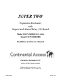
SUPER TWO
®
Expansion Enclosure
with
Supervised Alarm/Relay I/O Board
Model CICP1300IOENCL with
Model CICP1300IOBD
Installation and Service Manual
CONTINENTAL INSTRUMENTS LLC
A NAPCO SECURITY GROUP COMPANY
355 Bayview Avenue, Amityville, NY 11701
Phone: 631-842-9400 Fax: 631-842-9135
© NAPCO 2006
WI1515 4/06
1
Supervised Alarm / Relay / Expansion Unit
FCC Warning
Changes or modifications to this unit not expressly approved by the party responsible for compliance could void the user’s authority to operate the equipment.
NOTE
This equipment has been tested and found to comply with the limits for a Class A digital device, pursuant to Part 15 of the FCC
Rules. These limits are designed to provide reasonable protection against harmful interference when the equipment is operated in
a commercial environment. This equipment generates, uses, and can radiate radio frequency energy and, if not installed and used
in accordance with the instruction manual, may cause harmful interference to radio communications. Operation of this equipment in a residential area is likely to cause harmful interference in which the user will be required to correct the interference at
his own expense.
Shielded cables must be used with this unit to ensure compliance with the Class A FCC limits.
DISCLAIMER
Continental Instruments LLC makes no representations or warranties with respect to the contents hereof and specifically disclaims any implied warranties of merchantability or fitness for any particular purpose. Further, Continental Instruments LLC reserves the right to revise this publication and to make changes from time to time in the content hereof without obligation of Continental Instruments LLC to notify any person of such revision or changes.
Information furnished by Continental Instruments LLC is believed to be accurate and reliable. However, no responsibility is assumed by Continental Instruments LLC for its use; nor for any infringements of other rights of third parties which may result
from its use. No license is granted by implications or otherwise under any patent or patent rights of Continental Instruments
LLC.
Copyright © 2005 by Continental Instruments LLC. All rights reserved. No part of this publication may be reproduced, transmitted, transcribed, or stored in a retrieval system, without the prior written permission of Continental Instruments LLC, 355
Bayview Avenue, Amityville, NY 11701. 631-842-9400
A NAPCO SECURITY GROUP COMPANY
Supervised Alarm / Relay / Expansion Unit
2
THE INSTALLATION OF THIS PRODUCT SHOULD BE MADE BY QUALIFIED
SERVICE PERSONNEL AND SHOULD CONFORM TO ALL LOCAL CODES.
The lightning flash with arrowhead
symbol, within an equilateral triangle, is intended to alert the user to
the
presence
of
uninsulated
'dangerous voltage' within the product's enclosure that may be of sufficient magnitude to constitute a risk
of electric shock to persons.
CAUTION
RISK OF ELECTRIC SHOCK
DO NOT OPEN
CAUTION: TO REDUCE THE RISK OF ELECTRIC SHOCK
DO NOT REMOVE COVERS (OR BACK).
The exclamation point within an
equilateral triangle is intended to
alert the user to the presence of important operating and maintenance
(servicing) instructions in the literature accompanying the product.
NO USER-SERVICEABLE PARTS INSIDE
REFER SERVICING TO QUALIFIED SERVICE PERSONNEL
WARNING
UNPACKING AND INSPECTION
Unpack carefully. This is an electronic product and should be handled as such. Compare the items received with the packing list
with your order.
This product generates, uses, and can radiate
radio frequency energy and if not installed and
used in accordance with the instruction manual,
may cause interference to radio communications. It has been tested and found to comply
with the limits for a Class A computing device
pursuant to Part 15 of FCC Rules, which are designed to provide reasonable protection against
such interference when operated in a commercial environment. Operation of this product in a
residential area is likely to cause interference in
which case the user at his own expense will be
required to take whatever measures may be required to correct the interference.
BE SURE TO SAVE THE SHIPPING CARTONS
AND INSERT PIECES. THEY ARE THE SAFEST
MATERIAL IN WHICH TO MAKE FUTURE SHIPMENTS OF THE PRODUCT.
MAINTENANCE
WARNING
User maintenance of this unit is limited to external cleaning and inspection.
TO REDUCE THE RISK OF FIRE OR SHOCK HAZARD, DO
NOT EXPOSE THIS PRODUCT TO RAIN OR MOISTURE.
3
Supervised Alarm / Relay / Expansion Unit
TABLE OF CONTENTS
DESCRIPTION ................................................................................................................................. 5
IMPORTANT SAFETY INFORMATION ...................................................................................... 6
CONFIGURATION .......................................................................................................................... 7
PC Board Layout: Alarm/Relay Board ......................................................................................... 8
Additional Configurations ............................................................................................................. 9
INSTALLATION ............................................................................................................................ 10
Installation Preparation .............................................................................................................. 11
Cabinet Mounting ........................................................................................................................ 12
Cable and Wiring Categories ...................................................................................................... 13
Low-Voltage Power and Accessory Relay Devices ..................................................................... 13
Communication Cables................................................................................................................ 13
Accessory Conduit Knockouts ..................................................................................................... 13
Grounding Accessory Drain and Shield Wires ........................................................................... 13
Modular Cable ............................................................................................................................. 14
AUXILIARY POWER.................................................................................................................... 15
Replay Power ............................................................................................................................... 15
RELAY CONNECTIONS .............................................................................................................. 16
Description .................................................................................................................................. 16
Relay Characteristics .................................................................................................................. 16
ALARM CONNECTION ............................................................................................................... 17
Supervised Alarms ....................................................................................................................... 17
Configuring an Alarm in the Supervised Condition .................................................................... 17
Alarm Cable Requirements.......................................................................................................... 17
Tamper Switch ............................................................................................................................. 17
INTERNAL EXPANSION .............................................................................................................. 18
Installing the Supervised Alarm/Relay Board ............................................................................. 18
SPECIFICATIONS ......................................................................................................................... 19
SUPER TWO EXPANSION BOARD MAPPING ......................................................................... 20
INDEX ............................................................................................................................................. 21
WARRANTY .................................................................................................................................. 23
WIRING DIAGRAM ...................................................................................................................... 27
Supervised Alarm / Relay / Expansion Unit
4
DESCRIPTION
The enclosure is the same width as the Super Two housing, but
3” taller to contain the power supply and battery, and to allow
a channel for field wiring across the top inside the unit.
DESCRIPTION
The CICP1300IOENCL allows two CICP1300IOBD Supervised Alarm / Relay Boards to be installed (these may be purchased separately). No power supply or backup battery is provided. 12 Volt DC power for the relay circuits is required either from the Accessory Power output of the Super Two Access Control Panel, or from a CICP1300IOCOMBO unit that
also may provide accessory power.
The Access Control Panel and the Alarm/Relay Expansion
Unit(s) are connected and powered by short modular [RJ12]
cables provided. These cables must be routed through short
pieces of metal conduit. The 12 volt relay power wiring may
also be routed through this conduit.
The following is provided on each CICP1300IOBD PCB:
• Sixteen supervised inputs with performance matching that
of the ALARM inputs of the Super Two. A status change
is signaled by a half-second activation of an EVENT lamp.
• Sixteen relay outputs with LED indication of relay activation.
• An OK lamp that blinks to indicate correct operation of
the equipment.
• Status lamps show LOGIC power and 12V relay power.
A three-foot RJ12 cable is provided with each CICP1300IOENCL Expansion Enclosure, and a four-inch RJ12 cable is
provided with each Alarm/Relay Expansion Board.
Host Software Version 2.3.16 build 166 or later is required to
operate with the Supervise Alarm / Relay Expansion Board.
Firmware release 2.0.15 or later must be installed or
downloaded to the Access Control Panel.
The alarm circuits and alarm interface components receive 5
Volt power from the Access Control Panel through the modular cable. The correct connection to this power is shown by
the LOGIC Power LED. The 12 Volt power for the relays, the
relay indicators, the OK lamp, and the EVENT lamp must be
obtained from the Accessory Power Output of the Super Two
Access Control Panel or from an adjacent CICP1300IOCOMBO Expansion Unit. The correct connection and operation of this power is shown by the activation of the 12V lamp.
Because all relays may be activated at the same time, the 12
Volt power source must be able to supply at least 500mA for
each CICP1300IOBD Alarm/Relay expansion board.
Sixteen more alarm inputs and sixteen more relays may be
added into the enclosure by ordering and installing a second
CICP1300IOBD Supervised Alarm / Relay Board.
As with the original Superterm expansion boards, using three
boards, a total of 48 supervised inputs and 48 relays are added.
Each Super Two Access Contol panel may be configured to
monitor a total of 56 supervised alarm inputs, and may control
a total of 52 relay outputs. The three-board configuration will
require an additional enclosure.
The Expansion Enclosure offers a matching appearance to the
Super Two. A tamper switch is installed in each CICP1300IOENCL which may be monitored by an accessory alarm input of
the Super Two or by one of the inputs on the Supervised
Alarm / Relay Board.
5
Supervised Alarm / Relay / Expansion Unit
REGULATORY CONSIDERATIONS
IMPORTANT SAFETY INFORMATION
Fault-Tolerance, Fault Isolation, and Conditions that
may result in impaired operation.
The Super Two is defined as a Stand-Alone Access Control
System. The PC connection provides convenient setup and
monitoring of the system, but all decision-making for a cardholder’s authorizations at a particular time and place are made
by the Access Control Panel. Likewise, all time-controlled
relay activities and link functions of the Access Control Panel
and the Alarm/Relay Expansion Unit do not depend upon the
normal operation of the PC. During disruptions in the operation of the PC, or the communications link with the PC, Access Transactions, Alarm Events, and other activities are
logged in the individual Access Control Panel. When communication is restored, these buffered transactions are transferred
to the PC.
Sensing the status of the Accessory Alarm Inputs will be impaired by a cut cable or short-circuit in the Alarm Signal Circuit wiring. By installing end-of-line termination resistors, as
described in this manual, the Alarm Circuits may be supervised to detect such faults and indicate the need for a repair.
The Access Control Panel constantly exchanges data with the
Alarm/Relay Expansion Board through the modular cable. If
the cable is disconnected while the units are powered, no
equipment damage will occur, but setup data stored in the Expansion Board will be lost. When the cable is reconnected, the
relays will not be activated. Self-Test Firmware in the Access
Control Panel will detect this disruption, and restore the setup
data and relay activation within one minute. Resetting the Access Control Panel will immediately restore normal operation
of the Expansion Units. Because no power supply is included
in the CICP1300IOENCL Expansion Unit, 12 Volt power for
the relays and indicator lamps must be obtained from the Super
Two Access Control Panel or from a nearby CICP1300IOCOMBO. Whether powered from the ACC. PWR OUT terminals of the Battery-Top Charger in the CICP1300IOCOMBO
unit, or the 12V OUT on the CICP1300 PC Board, the requirements of Power-Limited wiring are assured by the use of selfresetting current limiting devices.
The Expansion Unit is to be installed in a secured area. Nevertheless, because opening the enclosure door gives access to
terminals that can allow false signals, a tamper switch is installed on the door. The tamper switch must be configured at
the host computer to signal an alert when the tamper switch is
an open-circuit. The tamper switch may also be configured to
activate the console relay, which may then be wired into a Burglar Alarm Signal Circuit or an Alarm Sounding Circuit.
In some localities, the Alarm Circuit and Relay Circuit wiring
may use UL Type CM or UL Type CL2 foil-shielded multiconductor and multi-pair cable. Where the AHJ’s (Authorities
Having Jurisdiction) require Plenum-Rated cabling, UL Type
CL2P cabling will be acceptable. In Canadian installations,
CSA CMG FT4 foil-shielded cabling may be used in nonplenum installations, and CSA CMP FT6 foil-shielded cabling
may be used in installations requiring plenum ratings.
Supervised Alarm / Relay / Expansion Unit
6
CONFIGURATION
CONFIGURATION
CICP1300IOENCL Enclosure shown with one
Supervised Alarm/Relay Board CIPC1300IOBD
installed.
GROUNDING REQUIRED
For the built-in Alarm-Contact Surge Protection to perform
effectively, the enclosure must be tied securely to earth
ground. The Super Two Access Control Panel and the
CICP1300IOCOMBO unit are effectively grounded through
the mains power connection. When the conduit is installed,
the knockout area near the conduit nut may be burnished to
assure that enough paint is removed to provide an effective
ground. Alternatively, a wire may be connected between one
of the many drain-wire studs on the CICP1300IOENCL and
one of the drain-wire studs on the Access Control Panel or a
CICP1300IOCOMBO.
Modular Cable - A three-foot, 6-Pin, 6-Conductor modular
cable is provided to supply the data and logic power connection to the Super Two or other compatible Access Control
Panel. This must be plugged into the right side of the
CICP1300IOBD Board, routed through metal conduit, and
plugged into the Modular Jack on the left side of the Super
Two Access Control Panel.
Component Layout is shown below.
Triple-Size Knockouts
for Conduit Clamps
Knockouts for
Conduit Clamps
Vents
Knockouts for
Through-theWall Cables
Drain Wire
Stud
Knockouts for
Conduit Clamps
Flange for
Door Lock
Cable Tie
Mounts
Tamper
Switch
Mounting Hole
Mounting Hole
Figure 1 - Expansion Unit Components
7
Supervised Alarm / Relay / Expansion Unit
CONFIGURATION
PC Board Layout: Alarm/Relay Board (CICP1300IOBD)
INDICATORS
• EVENT - Flashes on/off to indicate a change in any
Alarm Input status.
• OK - Flashes steadily to indicate a working connection to the control panel.
• RELAY - Indicates working power connection via
12V IN.
• LOGIC - Working 5 volt power from control panel.
• LEDs near Relays indicate activation of individual
relay.
ADDRESS
A jumper must be set to X1, X2, or X3.
Each Board must be set to a different address.
I/O SERIAL SIGNAL and LOGIC POWER
Connect to control panel or pass-thru connector
using the modular cable supplied.
12V IN
Powers the
relay coils
SIXTEEN SUPERVISED
ALARM INPUTS
May be configured as NormallyOpen / Normally Closed; Supervised (requiring termination resistors) or Unsupervised (requiring
plain electrical contacts).
RELAY CONTACTS
Normally-Open and Normally-Closed contacts
available. Contacts rated
2A 24V AC/DC.
Figure 2 - PC Board Layout
Supervised Alarm / Relay / Expansion Unit
8
CONFIGURATION
Additional Configurations
A second CICP1300IOBD Alarm/Relay Board may be installed as described on page 18. Then, a second
CICP1300ENCL Expansion Unit may be installed with one more CICP1300IOBD Alarm/Relay Board, bringing the
total number of Alarm/Relay boards to three.
Figure 3 - Installation of a second CICP1300IOBD Alarm/Relay Board
The wire harness provided with the CICP1300ENCL Expansion Unit allows it to be powered by an adjacent Access
Control Panel, but be mindful of the 500mA load that must be met by the 12 Volt power source for each Alarm/
Relay Board. With three Alarm/Relay boards installed, the total load rating is 1.5A, which is close to the 1.6A limit
for accessory loads on the Super Two.
Note: The maximum total length of modular cable to be used to connect the three Alarm/Relay Boards to the Access Control Panel is 9 feet (2.74 meters).
9
Supervised Alarm / Relay / Expansion Unit
INSTALLATION
About This Manual
INSTALLATION
This manual describes the installation of the Expansion Unit
Access Control Unit and the specific accessories that connect to
it.
Only qualified service personnel familiar with all local building
codes should attempt this installation. Take appropriate safeguards to avoid unintentional operation by employees and
maintenance personnel working about the premises.
End-User Periodic Tests and Emergency Planning
The Host Computer Software supervises the Access Control
System, reporting failures at an individual panel within seconds
of the occurrence. Nevertheless, failures can occur at the Door
Sense and Bypass contact monitoring hardware, the individual
Card Reader electronics and wiring, or the Electric Door Lock
Hardware that will not be detected until the equipment is used.
For this reason, please instruct staff at the installation to perform a "walk through" test at every controlled entrance and verify operation of all the monitored contacts at least once per
week, especially at sites that are less frequently used. Assist
the Security Staff at the installation to devise acceptable alternates to allow entrance and monitoring of access at controlled
sites impacted by equipment failures, especially in high-traffic
areas.
The installation of each Expansion Unit should be completed
and tested on its own before connecting into a network. Any
possible wiring or installation problems are magnified many
times by the complexity of the network.
Once an individual panel has been tested and found operating
satisfactorily, it can then be safely brought into the network.
The Expansion Unit is categorized as PERMANENTLY CONNECTED EQUIPMENT with fixed wiring. This system must
be installed within the protected premise in accordance with the
National Electrical Code (NFPA70), local codes, and the authorities having jurisdiction.
The following warnings are designed for the safety of the Expansion Unit install/service technician and for the continued
proper function of the Expansion Unit.
NOTES:
Supervised Alarm / Relay / Expansion Unit
Provide staff members at the facility with contact information
that will help assure the swift correction of equipment outages.
Notes are included with a procedure informing the installer about related material.
CAUTION
Cautions indicate that a particular process
requires special attention.
WARNING
Warnings indicate that a particular process
exposes the installer to live circuits or that
making wrong connections can lead to
equipment failure.
CAUTION
Do not place accessory circuit cables in the
same conduit sections containing power
cables.
10
INSTALLATION
and exiting the cabinet.
Installation Preparation
First, select a mounting location within a secure, limited access
area (see Figure 4). Note the type of wall construction that the
enclosure will be secured to.
•
•
•
•
Determine that adequate space is available for mounting
the Expansion Unit cabinet on a wall with no interference
from wires, pipes, or other obstructions.
Determine the directions of the cabling conduit exiting the
Expansion Unit cabinet. Confirm sufficient access to ceilings and/or walls before fitting the conduit lengths.
Knockouts at the back of the unit may be used for "hidden
wiring" installations.
NOTE: All Expansion Unit signal wiring and accessory
power circuits are certified as power limited. The use of
conduit is optional for these circuits.
Proper installation of the Expansion Unit cabinet requires
an area of free space measuring at least:
23 inches high (584mm)
X
20 inches wide (508mm)
X
4.0 inches deep (101.6mm)
•
Confirm that adequate free space exists on both sides of
the Expansion Unit cabinet for cabling conduit entering
Optional "hidden
wiring" installation
Expansion Unit
Panel Assembly
Figure 4 - Expansion Unit Installation Location
11
Supervised Alarm / Relay / Expansion Unit
INSTALLATION
NOTE: Mark the small oval portion of the cabinet screw
holes (see Figure 6, Detail A and B).
Cabinet Mounting
Inspect the mounting surface around the proposed installation
site. The mounting surface must be capable of supporting
10.75 lbs. (4.9Kg) plus any additional weight of the installation
hardware.
CAUTION
Use only suitable mounting hardware for the
type of wall construction encountered.
1.
2.
Determine the Expansion Unit cabinet mounting location.
Keep in mind that conduit will be used to connect the Expansion Unit to the Super Two Access Control Panel. If
the tops of the enclosures are kept on the same line, the
conduit connection will be simplified. The Expansion
Unit will normally be to the left of the Super Two Access
Control Panel.
3.
Place the Expansion Unit cabinet out of the way.
4.
Drill pilot holes to the required depth and size for the
mounting screws.
5.
Insert the top two mounting screws into the wall. Leave
approximately one quarter of the screw's length protruding
from the wall.
NOTE: Do not tighten screws completely at this time.
6.
Place the Expansion Unit cabinet over the mounting
screws. Secure the Expansion Unit cabinet to the mounting surface using the two lower screws, and then tighten
the remaining length of the screws.
Mark the four mounting holes against the mounting surface using the Expansion Unit cabinet as a template, or
using the measurements provided in Figure 5.
10 11/16" (27cm)
Detail B
15 11/16" (39.85cm)
Figure 5 - Expansion Unit Cabinet
Mounting Hole Dimensions
Expansion
Unit Cabinet
Detail A
Figure 6 - Expansion Unit Mounting Screws
Supervised Alarm / Relay / Expansion Unit
12
INSTALLATION
NOTE: This system must be installed within the
protected premise in accordance with the National
Electrical Code (NFPA70), local codes, and the
authorities having jurisdiction.
Cable and Wiring Categories
The wiring and cabling for the CICP1300IOENCL Expansion
Unit fall into two categories:
Low-Voltage Power and Accessory Relay Devices
12 or 5 volt Power, any accessory relay controlled devices
connected to the Panel, and any 12 volt Accessories receiving
battery-backed power from the panel. (These are powerlimited circuits, and normally do not require a licensed electrician to complete this work). The wiring inside the enclosure
must be kept at least 1/4" away from the high-power (black
and white pair) wires between the AC Terminal Block and the
Power Supply, as well as the Red and Blacks Leads between
the Battery and the PC Board.
Communication Cables
This category contains all the communication cabling between
the Expansion Unit and all communication equipment, all
alarm circuits, and all card reader devices. (These are powerlimited circuits, and normally do not require a licensed electrician to complete this work). The wiring inside
the enclosure must be kept at least 1/4" away
from the high-power wires, as described in the
paragraph above. NOTE: For proper operation
of the Expansion Unit, route EACH category of
cabling in SEPARATE conduit or bundle (i.e.,
DO NOT mix alarm and communication cables in the same
conduit as relay and power cables). Plenum-Rated cabling
may be required in certain installations. See Important Safety
Information, page 6.
Accessory Conduit Knockouts
All cabling for the Expansion Unit is routed through EIA standard 3/4-inch knockouts located on the left and right sides of
the cabinet (see Figure 7). On the top of the enclosure, threesize knockouts are available.
Grounding Accessory Drain and Shield Wires
Ensure electromagnetic compatibility and reliable performance
by keeping all accessory drain and shield wires as short as possible.
All accessory drain and shield wires connect to ground posts
mounted along the knockout strips on both sides of the Expansion Unit cabinet (see Figure 7).
The following procedures assure proper installation of all drain
and shield wires.
•
•
•
•
Carefully remove the cable jacket after the cable enters the
Expansion Unit cabinet.
Place the drain wires under the ground post screw. Trim
as needed.
Verify a good connection and tighten the ground post nut.
Connect the accessory wires to the appropriate terminal
strip on the Expansion Unit circuit board.
Knockouts for 1/2", 3/4" or
1" Conduit Connectors
Accessory Wire Drain
and Shield Ground
Posts
Knockouts for 3/4"
Conduit Connectors
Knockouts for 3/4"
Conduit Connectors
Incoming Power
Knockout
Figure 7 - Cabling Conduit Knockouts
13
Supervised Alarm / Relay / Expansion Unit
MODULAR CABLE
not followed, the product will not be damaged, but the system
will not work correctly.
Modular Cable
The Modular Cable carries Alarm Data to the Access Control
Panel and Relay Activation commands from the Access Control Panel. The modest power requirements of the Logic and
Alarm Circuits are provided from the Access Control Panel
through this cable. The relay coil power is supplied through
the 12V IN connector just above the Modular Jack on the right
side of the board.
The Modular Cable must be run through metal conduit between the system enclosures. The total length must not exceed
9 feet (2.74 meters).
When removing the cable, note that the latching lever is on the
side near the printed circuit board.
The first Alarm/Relay Board must connect to the Access Control Panel using the Jack on the right side of the board. A
Pass-through connector is on the left side of the board if additional boards are used. Always connect the cable between the
left of one board to the right of the next board. If this rule is
Figure 8 - Modular Cable Connection
Supervised Alarm / Relay / Expansion Unit
14
AUXILIARY POWER
RELAY POWER
The CICP1300IOENCL does not provide 12 Volt power that
may be used for the CICP1300IOBD Alarm/Relay boards.
Thus the power must be obtained from the Accessory Power
output of a Super Two Access Control Panel or a
CICP1300COMBO Alarm/Relay/Power Expansion Unit.
Each Alarm/Relay Board Kit is supplied with a suitable long
power cable for this reason. The cable may be extended if
needed, and it may be routed through the conduit connecting
the enclosure to the Access Control Panel.
Be careful to observe polarity when connecting to the ACC.
PWR OUT terminals of the Battery-Top Charger in the
CICP1300IOCOMBO unit, or the 12V OUT on the CICP1300
PC Board. The cable provided follows the convention:
• Red is Positive
• Black is Negative
Reverse polarity protection is provided, but normal operation
of the equipment will be disrupted.
NOTE: +12VDC current draw on the Super Two Access
Control Panel or the CICP1300IOCOMBO Expansion Unit is
limited to a total maximum of 1.60 Amps for Readers, EM
Locks, and Accessories.
WARNING
Observe Positive and Negative wire polarity between accessory devices and the Expansion Unit.
15
Supervised Alarm / Relay / Expansion Unit
RELAY CONNECTIONS
LED located near each relay will light when the associated
relay is activated.
• Metal oxide varistors (MOVs) are placed across the contacts to reduce electrical noise. The MOVs limit any noise
caused by the switching an inductive load to 56 volts.
RELAY CONNECTIONS
Description
Each Alarm/Relay board provides sixteen Form C relays to
control Area Entry, Shift Signaling Devices, etc. If used to
control high-voltage equipment such as outdoor lighting in
parking areas, a suitably-wired external relay must be added to
switch the high-voltage equipment.
NOTES:
• Installing a 56V MOV at the controlled device further reduces possible noise input.
• Additional MOVs are available from Continental Instruments as part number R783R.
• Because of this noise, relay wiring MUST NOT be put in
the same conduit with other wiring.
Relay Characteristics
The relays all share the following characteristics:
• Form C relay with a contact rating of 2A at 24V AC/DC.
• The Normally Open (NO), and the Normally Closed (NC)
contacts are the default state of non-energized relays. An
RLY 1
RLY 9
NC
C
NO
NC
C
NO
RLY 2
RLY 10
NC
C
NO
NC
C
NO
RLY 3
RLY 11
NC
C
NO
NC
C
NO
RLY 4
RLY 12
NC
C
NO
NC
C
NO
RLY 5
RLY 13
NC
C
NO
NC
C
NO
RLY 6
RLY 14
NC
C
NO
NC
C
NO
RLY 7
RLY 15
NC
C
NO
NC
C
NO
RLY 8
RLY 16
NC
C
NO
NC
C
NO
Figure 9 - Relay Contact and Accessory Power Outputs
Supervised Alarm / Relay / Expansion Unit
16
ALARM CONNECTION
Alarm Cable Requirements
ALARM CONNECTION
Connecting alarm sensors to the expansion board requires 22
AWG, stranded, shielded cables with drain wires.
CAUTION
Keep all drain wires short. Connect drain wires to
the ground posts located on both sides of the Expansion Unit cabinet. DO NOT ground drain
wires at any other point.
Each Alarm/Relay Board has a total of 16 supervised alarm
inputs. These are located on the top portion of the PC Board.
The inner columns use "Riser" Headers to ease wiring. These
alarm inputs may be used for dry contact type inputs
(unsupervised) or supervised alarms.
Supervised Alarms
Tamper Switch
Supervised alarms provide monitoring of alarm inputs for fault
or tamper conditions. Two additional alarm states may be detected by installing two-1K ohm resistors near the alarm contacts. In addition to the standard Normal and Abnormal alarm
conditions, the supervised alarms report line open and line
short conditions.
The Expansion Unit Enclosure has a built-in tamper switch.
The tamper switch is supplied with wiring sufficient to connect
to an Alarm Input of the Access Control Panel, and may be
extended with an in-line terminal block if desired. The Tamper switch wiring may be run in the same conduit with the
modular cable connecting the Expander Board to the Access
Control Panel. The leads may also be trimmed to connect to
one of the Alarm/Relay Board Alarm Inputs. The Tamper
switch is normally-closed when the enclosure door is closed.
The tamper switch must be configured at the Host Computer to
signal an Alert when the tamper switch is activated. The tamper switch may also be configured to activate the Console Relay that is wired to an alarm signal circuit or an alarm sounder.
• A line open condition is the result of a cut wire.
• A line short condition is the result of a short in the alarm
wiring.
These fault conditions may be the result of tampering, and indicate the system cannot correctly detect the state of the alarm
contacts.
Configuring an Alarm in the Supervised Condition
1. Use two 1K Ohm, 1/4W, ±5% carbon film resistors per
alarm.
2. Install R1 in parallel with the alarm contacts (see Figure
10).
3. Install R2 in series with the alarm input conductor.
NOTE: For maximum protection, install the resistors close to
the alarm contacts and embed them in epoxy.
Cabinet
Ground Post
Unsupervised
Sensor
Drain Wire/
Shield
1
Cabinet
Ground Post
Drain Wire/
Shield
R1=1K
Supervised
Sensor
R2=1K
4
Figure 10 - ALARM Terminal Strip - Unsupervised and Supervised Alarm Connections
17
Supervised Alarm / Relay / Expansion Unit
INTERNAL EXPANSION
Installing the Supervised Alarm/Relay (CICP1300IOBD) Boards
Locate the four
push-on "Snap"
Fasteners.
Locate the four 440 female PEM
Fasteners.
Note: Normally, the first Alarm/Relay
Board will be installed on the right side.
Position the board so the outer mounting
holes line up. Then carefully align the
board over the four snap fasteners. Press
on the upper eight relays with your palm,
applying increasing force while rocking
your palm until all four snaps are secured.
Install the four 4-40 screws (provided) in
the mounting holes on the outer part of the
board.
Figure 11 - Fastener Mounting Locations
Locate the 12V IN connector on the upper-right of
the board.
12V IN
When being installed in the CICP1300IOCOMBO
(with the power supply and battery) connect the small
white Molex Connector from the cable plugged into
RLY PWR OUT Connector.
When installed in the CICP1300ENCL (without the
power supply and battery) use the long cable provided to connect to the Accessory Power Connector
in the Access Control Panel. Note this cable may be
routed with the Modular cable in the same conduit.
Connect the Short Modular Cable (provided) between
the two Alarm/Relay boards.
Connect the Long Modular Cable (provided with the
enclosure) to the adjacent Super Two panel or
another I/O Expansion Unit.
Figure 12 - Power Connection Locations
Supervised Alarm / Relay / Expansion Unit
18
SPECIFICATIONS
SPECIFICATIONS
SPECIFICATION
Quantity
Comments
Relays
16 (each PDB)
per panel.
Form "C", contact rating of 2A @ 24V AC/DC
48 maximum per Super Two panel
Alarms
16 (each PDB)
per panel.
Supervised or non-supervised (host programmable)
48 maximum per Super Two panel
Status LEDs
16
4
Tamper Switch
1
One LED per relay
EVENT, OK, RELAY power, LOGIC power
Supply Voltage
12 Volts DC
Current Draw
500mA maximum
Weight
10.75 lbs (4.9kg)
Enclosure Dimensions (H x W x D)
18.75" x 13.85" x 3.25" (47cm x 35.2cm x 8.3cm)
Temperature Range
Operating
Storage
32-115°F (0-46°C)
32-149°F (0-65°C)
Relative Humidity
0% to 85% non-condensing
Link Programs
Cables
64
Standard
AWG
Type
Maximum Length
Alarm Inputs
22 ga
Stranded, shielded, w/drain 2-conductor alarm
500 ft (153m)
Relay Circuits
18 ga
Stranded, shielded, w/drain
500 ft (153m)
19
Supervised Alarm / Relay / Expansion Unit
APPENDIX A
SUPER TWO EXPANSION BOARD MAPPING
Expansion Board #1
Expansion Board #2
Relay
Input
Relay
Input
5
9
21
25
6
10
22
26
7
11
23
27
8
12
24
28
9
13
25
29
10
14
26
30
11
15
27
31
12
16
28
32
13
17
29
33
14
18
30
34
15
19
31
35
16
20
32
36
17
21
33
37
18
22
34
38
19
23
35
39
20
24
36
40
Expansion Board #3
Relay
Input
37
41
38
42
39
43
40
44
41
45
42
46
43
47
44
48
45
46
47
48
49
50
51
52
49
50
51
52
53
54
55
56
Supervised Alarm / Relay / Expansion Unit
VIRTUAL INPUTS
Reader 1
Function
Forced Door
Valid Tracked
Void /Denied Card
Open Too Long
Input
49
50
51
52
Reader 2
Function
Forced Door
Valid Tracked
Void /Denied Card
Open Too Long
Input
53
54
55
56
NOTE: Virtual Inputs are not available if
Expansion Board # 3 is used.
20
INDEX
MODULAR CABLE
LENGTH LIMITATIONS..........................................9
MODULAR CABLE ..............................................7, 14
MODULAR JACK .......................................................7
MOUNTING
CABINET ..............................................................12
MOUNTING LOCATIONS ........................................11
OK
INDICATOR............................................................8
PC BOARD LAYOUT .................................................8
PERIODIC TESTS ...................................................10
RELAY
INDICATOR............................................................8
RELAY CHARACTERISTICS ...................................16
RELAY CONNECTIONS ..........................................16
RELAY CONTACTS
RATINGS ...............................................................8
RELAY OUTPUTS .....................................................5
RELAY POWER .......................................................15
SAFETY INFORMATION ...........................................6
SHIELD WIRES .......................................................13
SHIELDED CABLING
REQUIREMENTS...................................................6
SOFTWARE VERSION
REQUIREMENTS...................................................5
SPECIFICATIONS ...................................................19
SUPERVISED ALARMS ..........................................17
SUPERVISED INPUTS ..............................................5
TAMPER SWITCH ...................................................17
VIRTUAL INPUTS ....................................................20
WARRANTY ............................................................23
WIRE POLARITY .....................................................15
WIRING
CABLE REQUIREMENTS ......................................6
WIRING
CATEGORIES ......................................................13
WIRING DIAGRAM ..................................................27
ACCESSORY POWER ......................................13, 15
ADDITIONAL CONFIGURATIONS.............................9
ADDRESS
JUMPER .................................................................8
ALARM CABLE REQUIREMENTS...........................17
ALARM CONNECTION ............................................17
ALARM INPUTS .......................................................17
BOARD LAYOUT .......................................................8
CABINET MOUNTING .............................................12
CABLE
REQUIREMENTS ...................................................6
CABLE
CATEGORIES ......................................................13
COMMUNICATION...............................................13
CICP1300IOBD
DESCRIPTION .......................................................5
INSTALLING .........................................................18
CICP1300IOENCL
DESCRIPTION .......................................................5
CIPC1300IOBD COMPONENTS................................7
CONFIGURATION .....................................................7
DRAIN WIRES .........................................................13
EVENT
INDICATOR ............................................................8
EXPANSION BOARD MAPPING .............................20
EXPANSION UNIT COMPONENTS ...........................7
GROUNDING
REQUIREMENTS ...................................................7
I/O SERIAL SIGNAL...................................................8
INDICATORS .............................................................8
INSTALLATION
PREPARATION ....................................................11
INSTALLATION ........................................................10
JUMPER ....................................................................8
KNOCKOUTS...........................................................13
LED
INDICATORS..........................................................8
LOGIC
INDICATOR ............................................................8
LOGIC POWER..........................................................8
21
Supervised Alarm / Relay / Expansion Unit
NOTES
Supervised Alarm / Relay / Expansion Unit
22
WARRANTY / TERMS & CONDITIONS
Standard Terms of Sale
• If customer believes an invoice to be in error, customer shall notify Continental of the error within
thirty (30) days.
Ordering
Orders for Continental products may be placed by
calling Continental’s order department or by issuing a
purchase order specifying the quantity of Products, the
desired delivery date, shipping method, and the location to which product should be shipped. If an order is
placed by telephone, it must be confirmed in writing
by fax or mail.
• Continental reserves a security interest in all products sold hereunder, together with all proceeds
thereof to secure the performance of the customer’s obligations hereunder.
• All orders unless otherwise requested are shipped
F.O.B. Amityville, NY.
If the customer requests a guaranteed ship date or expedited shipping, Continental reserves the right to add
to the price, with the customer’s approval, expenses
which increase the cost of production and delivery, i.e.
freight charges, overtime expenses, etc. Continental
reserves the right to change any price on this price list
and all prices are subject to factory reconfirmation at
the time of placing an order.
Cancelled Orders
Special or custom order items that cannot be cancelled
with our suppliers are subject to a 100% cancellation
charge.
No unauthorized, returned merchandise will be accepted for credit.
Orders returned or canceled are subject to a 25% restocking charge.
Sales Assistance
Continental will furnish to customers, reasonable
quantities of product-related catalogs and other sales
and promotional literature.
Return Material Authorizations
No products will be accepted for return to Continental
without prior written authorization (RMA). Unauthorized returns will not be accepted from the carrier by
the receiving department. The customer may request
a return material authorization (RMA), whether for
credit or repair of the product. Continental will either
issue an RMA or provide the customer with a written
explanation for not issuing the RMA. Except for warranty claims, no returns will be accepted more than 60
days after shipment from Continental. Orders that are
accepted for return are subject to a 25% restocking
charge. No product will be accepted for return which
has been special ordered or custom in nature.
Continental will provide customer training, both technical and sales at Continentals facilities in New York.
Contact the factory for costs and requirements.
Payment Terms
• Sales terms are Cash on Delivery (COD) unless
prior credit arrangements are established.
• If credit arrangements are established with Continental, terms of sale are net 10 days.
• Interest charges shall accrue on all past due accounts at a rate of 1.5% per month (18% APR).
• Continental reserves the right to place a customer
on a C.O.D. status in the event that customer’s account becomes delinquent or Continental becomes
unsure about customer’s financial capabilities.
Limited Warranty
Return Material Authorization (RMA) numbers are
required to be issued by Continental prior to returning
any Product for service, repair, credit or exchange.
Continental warrants that its Products shall be free
from defects in materials and workmanship for a pe-
• Continental will charge a Service Fee of $50.00
for any returned check.
23
Supervised Alarm / Relay / Expansion Unit
no Circumstances will Continental be liable for direct,
indirect or consequential damages of any kind.
riod of one year from date of shipment of the product
to purchaser. The warranty on 3rd party equipment
such as terminals, printers, and communications devices shall be 1 year from date of shipment. Remediation of this warranty shall be limited to the repair or
replacement of those products which are defective or
become defective under normal use. Continental’s
warranty shall not extend to any product which is
found after examination to be defective as a result of
misuse, improper storage, incorrect installation, operation or maintenance, alteration, modification or accident.
General Notices:
In order to assure that Continental’s customers receive
the most accurate and reliable information possible,
Continental at times monitors telephone calls
Information and pricing contained within this document are subject to change without notice.
Continental does not recommend that these products
be used as the primary means of monitoring, warning
or egress. Primary warning or monitoring systems
should always meet local fire and safety code requirements.
There are no other warranties which extend beyond
this provision. This warranty is in lieu of all other
warranties whether express, implied or statutory, including implied warranties of merchantability or fitness for any particular purpose. No representation or
warranty of the distributor shall extend the liability or
responsibility of the manufacturer beyond the terms of
this provision. In no event shall Continental be liable
for any costs, loss of profits, loss of use, incidental,
consequential or special damages to any person resulting from the use of Continental’s products.
This transaction shall be governed and construed in
accordance with the laws of the State of New York.
Continental specifically rejects any terms or conditions stated by the customer or contained within purchase documents or correspondence from the customer which are in addition to, conflict with or limit,
terms or conditions set forth herein. The customer’s
execution or other acceptance of this proposal or its
acceptance of delivery of all or part of the goods to be
delivered hereunder shall constitute customer’s acceptance of the terms and conditions herein and shall be
deemed to exclude any additional, conflicting or limiting terms stated by customer or contained in customer’s purchase documents or correspondence.
The above limited warranty is the only warranty provided by Continental. Continental makes no other
warranties or guarantees, whether expressed or implied, including, but not limited to, warranties and/or
guarantees of merchantability or fitness for a particular purpose. In no event shall Continental be liable for
any indirect, consequential or incidental damages, including those to person and those for lost wages, or
other economic loss.
Product Liability
Continental’s sole Liability and the customer's exclusive remedy for damages, shall not exceed the cost of
correcting the defect and in no event shall such liability be greater than the purchase price paid by the customer for the defective equipment or software. Under
Supervised Alarm / Relay / Expansion Unit
24
NOTES
25
Supervised Alarm / Relay / Expansion Unit
NOTES
Supervised Alarm / Relay / Expansion Unit
26
WIRING DIAGRAM
27
Supervised Alarm / Relay / Expansion Unit
CONTINENTAL INSTRUMENTS LLC
A NAPCO SECURITY GROUP COMPANY
355 Bayview Avenue, Amityville, NY 11701
Phone: 631-842-9400 Fax: 631-842-9135
Supervised Alarm / Relay / Expansion Unit
28