1
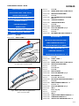
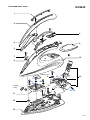
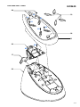
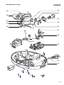
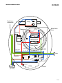
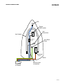
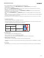
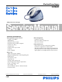
PerfectCare Aqua
GC8635
Philips Consumer Lifestyle
Service Manual
PRODUCT INFORMATION
Fast & powerful crease removal
• Soleplate: SteamGlide
• OptimalTemp
• Continuous steam output
• Continuous steam output: 120 g/min
• Steam boost: 220 g
• Vertical steam
• Steam pressure: Up to 5 bar
• Steam tip
• Power: 2400 W
Calc management
• Suitable for tap water
• Calc clean solution: Easy De-calc
• Calc clean reminder
Safety Information
• This product meets the requirements regarding
interference suppression on radio and TV.
• After the product has been repaired, it should function
properly and has to meet the safety requirements and
legal regulations as officially laid down at this moment.
Easy to use
• Water tank capacity: 2200 ml
• Filling and emptying water: Extra large filling hole
• Refill any time
• Heat-up time: 2 min
• Safety auto off
• Storage solution: Carry lock
• Hose storage: Hose storage compartment
• Power cord length: 1.8 m
• Hose length: 1.6 m
• Safe for all fabrics: Even for delicates like silks
• Low water alarm
Published by Philips Consumer Lifestyle
12/07
Printed in the Netherlands
© Copyright reserved
Subject to modification
TECHNICAL INFORMATION
Voltage
Frequency
Power
Dimension (F-box)
Weight of iron
Weight of iron + base
:
:
:
:
:
:
GC8635
220 - 240 V
50 - 60 Hz
2400 W
362 (D) x 270 (W) x 263 (H) mm
1 kg
4.5 kg
Water advice
Suitable for tap water use. Advice to mix with equal
portion of distilled water or use only distilled water if the
tap water is very hard.
Soleplate: Steam Glide
New SteamGlide soleplate is the best Philips soleplate. It
has great scratch resistancy, glides excellent and is easy to
clean.
OptimalTemp Technology
- Always deliver 1 perfect setting for all your clothes
thanks to:
1. Cylonic steam chamber
2. Advance Smart control processor
- 100% easy to use, no adjustment required.
- 100% safe on all delicate fabrics.
- 100% fast on the toughest fabrics.
Tested and approved by experts
Tested and approved by independent textile experts
institutes.
Steam pressure: Up to 5 bar
Double your ironing speed with pressurized steam.
2.2L fully visible water tank
Large water tank ensures long hours of ironing without
refill of water tank.
Lock your iron securely
Lock your iron securely and carry your steam generator
easily.
Easy De-Calc
Easy De-Calc, hassle free & effective scale removal to
extend the life of your steam generator.
2-13
GC8635
DISASSEMBLY ADVICE - IRON
LIGHT STRIP CAP ASSY 1
INLAY AND LIGHT STRIP ASSY 2
REFLECTOR MOLDED 3
Remove
Disassemble
Disassemble
Remove
Disassemble
LED MICROSWITCH HOLDER ASSY 4
TRIGGER SPRING 5
TRIGGER MOLDED 6
MICA PLATE 7
PLASTIC WASHER (1x) 8 (FRONT)
DECORATION CAP PRINTED 9
Remove
Disassemble
Disassemble
Disassemble
Remove
Disassemble
Disassemble
Remove
Remove
Disassemble
Screw A
LIGHT STRIP 1
Screw B
INLAY AND LIGHT STRIP ASSY 2
REFLECTOR MOLDED 3
Screw C
LED MICROSWITCH HOLDER
ASSY 4
TRIGGER SPRING 5
TRIGGER MOLDED 6
Screw D
MICA PLATE 7
PLASTIC WASHER (1x) 8
Screw E1, E2
Screw F
DECORATION CAP PRINTED 9
RYTON RING 10
DEVIATOR HOUSING MOLDED 11
IRON THERMISTOR ASSY 12
PLSTIC WASHER (2x) 8 (REAR)
HOSE CORD MOUNTED ASSY 14
HOUSING PRINTED 15
SOLEPLATE MOUNTED ASSY 16
Fig 1. Using “-” screw driver to lift up the Inlay and release
the catch at the end of the handle.
Apply forces
Fig 2. Position of the catch to be applied forces
at the end of the handle.
Remove
Disassemble
Remove
Disassemble
Disassemble
Remove
Remove
Remove
Disassemble
Disassemble
Disassemble
Remove
Disassemble
Remove
Disassemble
Remove
Disassemble
Disconnect
Release
Remove
Disconnect
Disassemble
Disassemble
Disassemble
Screw A
LIGHT STRIP 1
Screw B
INLAY AND LIGHT STRIP ASSY 2
REFLECTOR MOLDED 3
Screw C
Screw E1, E2
Screw D
MICA PLATE 7
PLASTIC WASHER (1x) 8
RYTON RING 10
Screw G1, G2, G3, G4
DEVIATOR HOUSING MOLDED 11
Screw H
IRON THERMISTOR ASSY 12
Screw I1, I2
PLASTIC WASHER (2x) 8
Wires
Hose clip (2x)
Screw J
Wires
HOSE CORD MOUNTED ASSY 14
HOUSING PRINTED 15
SOLEPLATE MOUNTED ASSY 16
3-13
GC8635
PARTS LIST - IRON
Pos
Service code
Description
1
2
3
4
4239 021 70734
4239 021 70841
4239 026 49561
4239 021 71942
Light strip cap assy
Inlay and light strip assy
Reflector molded
LED microswitch holder assy
5
6
7
8
4239 014 54961
4239 026 50372
4239 010 12911
4239 026 49501
Trigger spring
Trigger molded
Mica plate
Plastic washer
9
10
11
12
4239 021 70901
4239 015 70153
4239 026 49491
4239 021 69942
Decoration cap printed
Ryton ring
Deviator housing molded
Iron thermistor assy
14
15
16
4239 021 71992
4239 021 70692
4239 021 70651
Hose cord mounted assy
Housing printed
Soleplate mounted assy
4-13
GC8635
EXPLODED VIEW - IRON
1
B
2
C
4
5
A
6
9
3
D
F
7
15
8
I1
Rubber pad
8
G1
G2
G4
8
I2
14
G3
12
Rubber
bung
E1 E2
H
11
10
16
5-13
GC8635
DISASSEMBLY ADVICE - STAND
FILLING DOOR MOLDED 17
RINSE CAP ASSY 24
REAR LOCK RUBBER 18
SAFETY CAP 25
TRAY RUBBER CAP 19
INOX CLAMP 26
TRAY CAP MOLDED 20
BRAIDED RUBBER HOSE BOILER 27
TRAY PRINTED 21
ELECTROVALVE 28
FRONT LOCK ASSY 22
SPACER TOP 29
WATER TANK ASSY 23
RINSE HOUSING CAP PRINTED 30
Disassemble
Disassemble
Remove
Remove
Remove
Remove
Disassemble
Remove
Disassemble
Remove
Disassemble
FILLING DOOR MOLDED 17
REAR LOCK RUBBER 18
TRAY RUBBER CAP 19 (4x)
Screw K1, K2, K3, K4
TRAY CAP MOLDED 20 (2x)
Screw L1, L2
TRAY PRINTED 21
Screw M1, M2
FRONT LOCK ASSY 22
Screw N1, N2, N3, N4, N5
WATER TANK ASSY 23
RINSE HOUSING MOLDED 31
O-RING 32
BOILER ASSY 33
BOILER SUPPORT BRACKET 34
SPACER BOTTOM 35
BOILER THERMISTOR ASSY 36
Disassemble
Remove
Disassemble
Remove
Release
Disassemble
Release
Disconnect
Disassemble
Remove
Remove
Remove
Remove
Disassemble
Remove
Disassemble
Disassemble
Disassemble
Disassemble
Remove
Disassemble
RINSE CAP ASSY 24
Screw N1, N2, N3, N4, N5
WATER TANK ASSY 23
SAFETY CAP 25
INOX CLAMP 26 (2x)
BRAIDED RUBBER HOSE BOILER 27
Hose clip
Wires
ELECTROVALVE 28
Screw O1, O2
Screw P
SPACER TOP 29
Screw Q
RINSE HOUSING CAP PRINTED 30
Screw R
RINSE HOUSING MOLDED 31
O-RING 32
BOILER ASSY 33
BOILER SUPPORT BRACKET 34
SPACER BOTTOM 35
BOILER THERMISTOR ASSY 36
6-13
DISASSEMBLY ADVICE - STAND
GC8635
POWER BUTTON PRINTED 37
BUTTON FRAME PRINTED 38
POWER BOARD PCB-PUMP
SERVICE KIT 39
POWER CORD EU 40
STAND BOTTOM MOLDED 41
Remove
Disassemble
Remove
Disassemble
Disassemble
Remove
Release
Disassemble
Disconnect
Disassemble
Remove
Disassemble
Disassemble
Disassemble
Screw N1, N2, N3, N4, N5
WATER TANK ASSY 23
Screw S1, S2, S3
POWER BUTTON PRINTED 37
BUTTON FRAME PRINTED 38
Screw T
INOX CLAMP 26 (2x)
BRAIDED RUBBER HOSE BOILER 27
Wires
POWER BOARD PCB-PUMP
SERVICE KIT 39
Screw U1, U2
Cord clamp
POWER CORD EU 40
STAND BOTTOM MOLDED 41
7-13
GC8635
PARTS LIST - STAND
Pos
Service code
Description
17
18
19
20
21
4239 026 50134
4239 015 59741
4239 015 59731
4239 026 51841
4239 021 71512
Filling door molded
Rear lock rubber
Tray rubber cap
Tray cap molded
Tray printed
22
23
24
25
26
4239 021 71493
4239 021 71523
4239 021 70862
4239 015 59791
4239 010 10261
Front lock assy
Water tank assy
Rinse cap assy
Safety cap
Inox clamp
27
28
29
30
31
4239 015 59771
4239 017 12802
4239 026 51241
4239 021 72612
4239 026 49732
Braided rubber hose Boiler
Electrovalve
Spacer top
Rinse housing cap printed
Rinse housing molded
32
33
34
35
36
4239 015 59751
4239 021 69891
4239 026 42581
4239 026 32181
4239 021 69951
O-ring
Boiler assy
Boiler support bracket
Spacer bottom
Boiler thermistor assy
37
38
39
40
4239 021 70772
4239 021 70762
4239 022 67101
2422 070 98403
2422 070 98424
Power button printed
Button frame printed
Power board PCB-Pump service kit
Power Cord EU
Power Cord AU
41
4239 026 50112
Stand bottom molded
8-13
GC8635
EXPLODED VIEW - STAND
20
19
L2
L1
K2
K1
K3
K4
18
21
22
M2
M1
17
23
9-13
GC8635
EXPLODED VIEW - STAND
32
33
O2
31
28
24
O1
25
P
29
30
Q
R
35
34
36
S2
37
S3
S1
38
27
26
39
T
U2
U1
40
41
N1
N3
N2
N4
N5
10-13
GC8635
WIRING DIAGRAM STAND
Earth Interconnection
Pump
Boiler Earth
Point
WA20 : HE (N)
- Fuse (N)
Thermistor
WA19 : HE (L)
- Fuse (L)
WA7 - PCB
to EV-Ctrl
Thermal Fuse
E-valve
Thermal Fuse
WA5 : Fuse
(L) - PCB
WA2 - PCB to
Pump-Ctrl
Boiler Heater
WA3 : Earth
Wire_Boiler
WA6 : Fuse
(N) - PCB
Flex
WA1 - PCB to
EV-Pump-Live
Pump-EVLive
Flex Live
Iron
Live
Iron
Neutral
Boiler
Neutral
Thermistor
Boiler
Flex
Neutral
EV
Ctrl
Pump
Ctrl
Comms
Boiler Live
PCBA
STAND
Hosecord
(to Iron)
11-13
GC8635
WIRING DIAGRAM IRON
LED
Trigger
micro-switch
Iron
Thermistor
Iron Heater
JST eSL 3-way
wite-to-wire
connector
Iron Earth
Point
Thermal
Fuse
IRON
Hosecord
(to Stand)
Mid-air crimp
connection
12-13
GC8635
REPAIR INSTRUCTIONS
• Due to the high wattage of the iron, only the specified cord set must be used.
• Should damage be observed on the HOSE-CORD ASSY 14 or CORDSET 40, they must be replaced.
Continued usage is not allowed.
• When replacing the MICROSWITCH ASSY 4, please dress the 2 attached wires such that they are free of tension.
Pulling force on the wires may affect the steam triggering.
• To avoid damage to the sealing & components of the BOILER ASSY 33, NEVER clean the boiler assy with vinegar,
descaling agent or other corrosive chemicals.
• When replacing ELECTROVALVE 28 or PUMP ASSY 39, please be reminded to apply loctite at the joints for good
sealing.
• After the product has been repaired, it should function properly and has to meet the safety requirements & legal regulations
as laid down & officially established at this moment.
• The following tests are common checks that are conducted on a repaired product before it is returned to the consumer.
1. Soleplate temperature
Check that soleplate temperature is within IEC requirement.
Measure the temperature of the soleplate after the iron has reached steady state i.e connected to the mains for at least
15 minutes. The table below shows the temperature requirement.
=
Soleplate temperature (Deg C)
Materials, for example
Maximum
120
143
Testpoint
=
Minimum
All fabric types
2. Leakage current
Check that leakage current is within IEC requirement.
Measure leakage current between LIVE/NEUTRAL & EARTH.
IEC requirement is that at 230 V supply, the EARTH leakage current must be less than 0.75 mA.
3. Water leakage / Functionality
Check that there is no water leakage from any part of the product during operation.
Check that the functionality of the product (product dependent) eg. steaming, variable steam, SOS, ASO etc is working
properly.
4. Loose part
Check that there are no loose parts eg. extra screw in the product that can cause short-circuit or product malfunction.
13-13