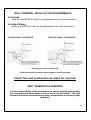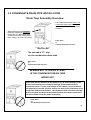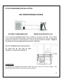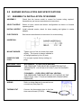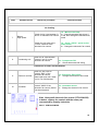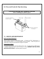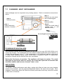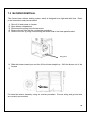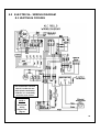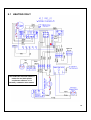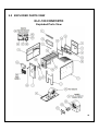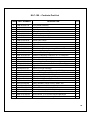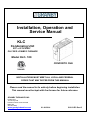
1
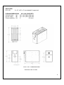
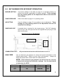
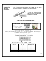
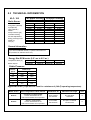
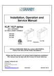
Installation, Operation and
Service Manual
KLC
Condensing Unit
95% + EFFICIENCY
OIL FIRED LOWBOY FURNACE
Model KLC- 100
CONFORTO CHE
INSTALLATIONS MUST MEET ALL LOCAL AND FEDERAL
CODES THAT MAY DIFFER FROM THIS MANUAL
Please read the manual in its entirety before beginning installation.
This manual must be kept with the furnace for future reference.
GRANBY FURNACES INC.
PO Box 637
12118 Hwy 209
Parrsboro Nova Scotia Canada
B0M 1S0
902-254-2543
www.granbyindustries.com
01-24-2014
G2012-E3 Rev.G
WARNING
This furnace is designed to operate with the ALL 20 flue-pipe baffles
correctly installed. The maximum normal flue temperature is 125
Degrees °F after 10 minutes of operation at a maxim um distance of 18
inches from the breach of the unit.
IT IS MANDATORY TO MEASURE THE FLUE-PIPE TEMPERATURE,
as part of the combustion test, UPON INSTALLATION. This
measurement must be taken as close as possible to the breech of the
unit, through the plastic flue pipe downstream of the black rubber
connector. To do this check, simply make a small hole (large enough
for your temperature probe) in the flue pipe. Upon completion of the
test, cover the hole with HVAC aluminum tape.
If the temperature is OVER 125 Degrees °F:
1. Check that ALL 20 baffles are in place. To do this you must
remove the black plastic collector pan as described in section 7.1;
2. Check that the correct nozzle is installed in the burner;
3. Check that you have the correct burner pump pressure;
4. Make sure the blower door is closed during operation;
5. Make sure that the condensate disposal system is not blocked. If
that is the case, unblock.
IF THE UNIT IS STILL OPERATING OVER 125 DEGREES F AFTER
THESE CHECKS, CALL GRANBY FURNACES INC. “CUSTOMER
CARE”.
PROLONGED OPERATION OVER 125 DEGREES ºF COULD LEAD
TO UNSAFE OPERATION, PREMATURE FAILURE OF THE
EQUIPMENT AND BODILY HARM.
1
TABLE OF CONTENTS
1.0
IMPORTANT SAFETY ADVICE
3
2.0
PRODUCT INFORMATION
4
3.0
FURNACE INSTALLATION
3.1 PLACEMENT & VENTING
3.2 INSTALLATION CODES
3.3 INSTALLATION INFORMATIONS
3.4 VENTING OPTIONS
3.5 CONDENSATE DRAIN LINE INSTALLATION
6
7
8
8
8
11
4.0
ACCESSORIES INSTALLATION
12
5.0
BURNER INSTALLATION AND SPECIFICATIONS
5.1 ASSEMBLY & INSTALLATION OF THE BURNER
5.2 SET BURNER FOR EFFICIENT OPERATION
5.3 TECHNICAL INFORMATION
13
13
14
16
6.0
FURNACE OPERATION AND SETTINGS
17
6.1 BLOWER SETTING
17
6.2 FAN TIMER CONTROL BOARD (ST9103 A 1028)
18
6.3 (ST9103 A 1028) CONTROL BOARD SEQUENCE 19
6.4 SERVICING – FAN TIMER (ST9103 A 1028)
20
6.5 FLUE AND FRESH AIR PIPE SERVICING
23
7.0
SERVICE AND MAINTENANCE
7.1 CLEANING HEAT EXCHANGER
7.2 BLOWER REMOVA L
23
24
25
8.0
ELECTRICAL / WIRING DIAGRAM
8.1 HEATING & COOLING
8.2 HEATING ONLY
26
26
27
9.0
EXPLODED PARTS VIEW
28
10.
START-UP TEST RESULTS
30
2
1.0 IMPORTANT SAFETY ADVICE
Please read and understand this manual before installing, operating or servicing the
furnace. To ensure you have a clear understanding of the operating procedures of the unit
please take the time to read the IMPORTANT SAFETY ADVICE section of this manual. This
furnace is equipped with an electronically commutated motor (ECM) for the main circulation
blower. The ECM will significantly reduce the electrical power consumption and will enhance
home comfort.
WARNINGS
NEVER burn garbage or paper in the unit.
NEVER store combustible material around it.
DO NOT attempt to start burner when excess oil has accumulated, when unit is full of vapour
or when heat exchanger is very hot.
DO NOT use gasoline, crankcase draining’s or any oil containing gasoline.
CAUTION
DO NOT START THE BURNER UNTIL ALL FITTINGS, COVERS AND DOORS ARE IN
PLACE. DO NOT TAMPER WITH THE FURNACE OR CONTROLS, CALL A QUALIFIED
BURNER TECHNICIAN. DO NOT STORE OR USE GASOLINE OR OTHER FLAMMABLE
VAPOURS AND LIQUIDS IN THE VICINITY OF THIS UNIT OR ANY OTHER APPLIANCE.
DANGER
Do not use this furnace as a construction heater. Use of this furnace as a construction
heater exposes it to abnormal conditions, contaminated combustion air and lack of air
filtering. Failure to follow this warning can lead to premature furnace failure which could
result in a fire hazard and/or bodily harm and/or material damage.
NOTE: DO NOT INSTALL IN SPACE WHERE TEMPERATURE DROPS BELOW 32oF (0oC)
FREEZING POINT. CONDENSATE WILL FREEZE AND WILL DAMAGE UNIT.
IMPORTANT
This manual contains instructional and operational information for the KLC OIL-FIRED
FURNACE. Read the instructions thoroughly before installing furnace or starting the burner.
Consult local authorities about your local FIRE SAFETY REGULATIONS. All installations must
be in accordance with local state or provincial codes. Improper installation will result in voiding
of warranty.
3
2.0 PRODUCT INFORMATION
CLEARANCE (minimum) TO COMBUSTIBLES
Top of Supply Plenum
1”
(25 mm)
Front (Maintenance)
24”
(610 mm)
Rear (Maintenance)
24”
(610 mm)
Side – Non-Access
1”
(25 mm)
Side – Access maintenance
24”
(610 mm)
Vent Pipe
0”
(0 mm)
Floor (Can be installed directly on combustible or non-combustible)
AIR/BLOWER DATA
Maximum external static pressure
Maximum cooling unit capacity
Maximum air temperature rise
High Limit temperature
Thermostat anticipator
0.5” wc
3.0 tons.
See pages 16 and 31
215°F
See thermostat instructions
MOTOR/BLOWER
KLC-100: 1/2 hp ECM / GT12-10
FAN/HIGH LIMIT CONTROL
Honeywell ST9103A1028 Fan Center & Thermo-Disk (7” stem)
THERMOSTAT
Any wall thermostat
FUEL
Not heavier than No. 2 furnace oil.
ELECTRICAL – 120 Volts, 60 Hz
Canada
Less than 12 amps, circuit protection 15 amps.
USA
13.3 amps, circuit protection 20 amps.
VENT PIPE CONNECTION
3’’ IPEX 636
CONDENSATE DRAIN
PLASTIC HOSE ½’’ diameter
CLEANOUTS
Rear Cover & Burner Opening
4
AIR FILTER
KLC-100
2 x 12” x 20” x 2” non pleated UL approved
PLENUM DIMENSIONS
KLC-100 CONFORTO
Cold air return
(A)
20” x 20” (508 x 508 mm)
Hot air supply
(B)
20” x 20” (508 x 508 mm)
Plenum spacing (C)
3”
(76 mm)
KLC-100 - DIMENSIONS
Dimensions are in inches
5
3.0 FURNACE INSTALLATION
OIL TANK & PIPING
Tank installation must conform to local requirements.
Install according to the applicable code such as CSA B139 and NFPA 31. Minimize number of
connections in suction line and make all connections air tight. Use a pipe joint compound
suitable for oil on all pipe threads. To reduce possibility of air leaks, tighten stem packing
gland nut on any valves installed in the suction line. Also, be sure the oil filter is tight, as filter
gaskets often shrink. Check for kinks in the oil lines as well as for possible air pockets and for
loose connections. Two filters as shown below are recommended. Optional tank gauge
protectors and outlet protectors are available at your local dealer.
ONE PIPE SYSTEM
Where the tank outlet is above the burner and when the oil flows by
gravity to the oil pump, a single-stage fuel unit with a single oil line
to the pump may be used.
TWO PIPE SYSTEM
When a single line is not suitable, use double line or contact your
dealer for special oil line fittings. Install by-pass plug on burner fuel
pump as specified in the burner manual.
Rear Flue Furnace illustration
See page 9
for vent
options
installation.
Oil Tank and Piping
6
3.1 PLACEMENT & VENTING
Furnace installation shall conform to the required installation code for oil-fired
equipment (USA: NFPA 31, Canada: CSA B139).
FLOOR SUPPORT
COMBUSTIBLE – If required, support furnace on five (5) concrete
blocks. Make sure the center of the furnace base is supported. For a
furnace installed on a combustible floor, consult the applicable code and
authorities having jurisdiction on this application. The floor must support
the weight.
VENT
The KLC can be vented vertically through the roof or horizontally through
the wall. The appropriate venting material must be rated to a minimum
operating temperature of 65oC (149oF). The approved vent material is
ULC IPEX S636 PVC-40 in Canada and IPEX S636 PVC-40 (or its
equivalent) in the United States. Keep vent/flue pipe as short as possible
with a minimum. 1/4” per foot upward slope. See section 5.3 for more
information.
.
WARNING
BE AWARE THAT REMOVING BAFFLES REDUCES THE UNIT’S
EFFICIENCY AND INCREASE THE OUTLET TEMPERATURE. A
MODIFIED UNIT IS NO LONGER ENERGY STAR APPROVED.
THIS COULD RESULT IN FIRE HAZARD AND/OR OTHER
HAZARDOUS CONDITIONS THAT MAY LEAD TO BODILY HARM.
COMBUSTION &
VENTILATION AIR
Install openings and ductwork to the furnace room providing fresh outside combustion and circulation air for cooling the furnace casing, as
installation code requires (USA NFPA 31, Canada CSA B139). If
installed in a closed room, provide two free air ventilation openings of at
least 8” x 12” (96 sq. in.) free flow area near ceiling and floor. Oil
burners must have sufficient air to allow vent systems to operate
properly. If balance flue burner his used, combustion air must be duct to
the outside as per instructions.
ELECTRICAL
Wire according to the National Electrical Code (Canadian or USA) or
local codes. Use a separately fused #12 electrical line directly from the
service panel to the furnace junction box. Install a manual shut-off
switch at the door or stairway to furnace room so furnace can be shut off
remotely.
CLEARANCES
Before placing unit, review installation clearances as shown on furnace
operating decal or section PRODUCT INFORMATION (page 4).
7
BLOWER DOOR
Do not operate without blower door properly installed. This could result in
fire hazard and/or hazardous conditions that may lead to bodily harm.
3.2 INSTALLATION CODES
INSTALLATION MUST COMPLY WITH THE REQUIREMENTS OF AUTHORITIES HAVING
JURISDICTION. . All local and national codes governing the installation of oil burning
equipment, wiring and venting must be followed. Some of the applicable codes are:
CAN/CSA B 139
NFPA 31
ANSI/NFPA 90B
ANSI/NFPA70
CSA C 22.1
ANSI/NFPA 211
Installation Code for oil burning Equipment
Installation Code for Oil Burning Equipment
Warm Air Heating and Air Conditioning Systems
National Electrical Code
Canadian Electrical Code
Chimneys, Fireplaces, Vents and Solid Fuel Burning Appliances
The latest versions of the above codes that have been approved for use in the location of the
installation must be used.
3.3 INSTALLATION INFORMATIONS
VENT PIPE
See NFPA 31 (USA) or CSA B139 (Canada) code. Breech is certified for
3’’ ULC IPEX S636 PVC-40 vent pipe in Canada and IPEX S636 PVC-40
(or its equivalent) in the United States The appropriate venting material
must be rated to a minimum operating temperature of 65oC (149oF). See
section 5.3 for more technical information.
RETURN AIR
Ensure that the furnace return air temperature to the unit is not lower than
50oF (10oC)
3.4 VENTING
IPEX System 636 in 3 inch diameter is recommended for the KLC. The Installation
Methods to be used are detailed in the manual available at : http://www.ipexinc.com . An online
Solvent Cementing Course is also available at that site.
The minimum vent linear length is 5 feet. The maximum horizontal equivalent length allowed
is 80 feet. Each 90o elbow accounts for 8 feet. As an example if the system has 5 elbows, 40
linear feet of vent can be used. The vent is connected to the furnace using the supplied
neoprene coupling.
8
VENTING OPTIONS INSTALLATION
TWO PIPES SYSTEM
COAXIAL SYSTEM
Two small openings of 3’’1/2+
Single opening of 4’’1/2+
BF3 Riello burner approved
BF3 Riello burner approved
VERTICAL ONE PIPE SYSTEM
Especially for retrofit installation
Easy to fit one pipe in 7”x7” chimney tile
Avoid wall opening
No clearance restriction
Perfect where there is no access to external
wall in the mechanical room
F3 Riello burner approved
9
WALL TERMINAL INSTALLATION REQUIREMENTS
In Canada
Refer to the CSA B139 Code for the placement of the vent termination
In United States
Refer to the NFPA31 Code for the placement of the vent termination
COAXIAL WALL CLEARANCE
TWO PIPES WALL CLEARANCE
All piping must be on same wall
0utlet termination clearance above grade and roof overhang
Check flue and combustion air pipes for any leak
VENT TERMINATION WARNING
It is the responsibility of the homeowner to ensure that the area around
the vent terminal and air intake is free of snow, ice and debris. The vent
terminal should be checked during heavy snowstorms to ensure proper
operation.
10
3.5 CONDENSATE DRAIN PIPE INSTALLATION
Drain Trap Assembly Overview
The condensate drain tube must have
a downward slope to the drain of the
residence to provide a flow free of any
resistance.
Before starting the unit add water
Inside the collector pan through the
breech hole (3’’). Add enough water
so that you see water coming out the
tube coming out from the furnace.
Floor drain
or
condensate pump reservoir
“ Not to do”
Do not add a ‘’P’’ trap
on the condensate drain tube
Floor drain
or
condensate pump reservoir
BEWARE NOT TO CREATE A ‘KINK’
IN THE CONDENSATE DRAIN TUBE
IMPROTANT
Please note that the warranty to this product may be void if damages to the
furnace heat exchanger are caused by blockage of the condensate fluid
evacuation system. It is the responsibility of the installer, service technician
and homeowner to make sure that nothing can obstruct the evacuation of the
condensate fluid from the furnace. The condensate fluid neutralizer cartridge
must be changed annually and the condensate fluid evacuation system must
also be verified annually for proper functioning.
Floor drain
Or
condensate pump reservoir
11
4.0 ACCESSORIES INSTALLATION
AIR CONDITIONING SYSTEM
OUTSIDE CONDENSER UNIT
INSIDE EVAPORATOR COIL
An air conditioning evaporator coil may be installed on the supply side only. Coils installed
on the return side will cause damage on the unit; this will shorten the unit life and may cause
products of combustion to enter the house. Wire as per wiring label and diagram. Height of
the coil above the unit supply shall be at least 4” (102 mm).
See A/C coil Manufacturers Requirements.
To check the AC coil total air flow
resistance, see procedure at page 31.
HUMIDIFIER
If a humidifier is installed ensure that no water can drip or run from it into the furnace. This
would cause deterioration and void the furnace warranty.
12
5.0 BURNER INSTALLATION AND SPECIFICATIONS
5.1 ASSEMBLY & INSTALLATION OF BURNER
ASSEMBLY
Check that the burner model is correct for furnace rating required.
Assemble as per burner manufacturer’s instructions.
SELECT NOZZLE
Select oil input, nozzle and burner configuration as shown on furnace
operating decal.
INSTALL NOZZLE
Install selected nozzle, check for clean seating and tighten in nozzle
adaptor.
ELECTRODES
See burner manufacturer’s instructions for correct setting
INSERTION
MOUNT BURNER
Tighten top nut first so burner tips down
slightly. The burner is always installed in
an upright position by four (4) nuts.
PUMP BY-PASS
PLUG
For one pipe system factory setting (no
plug).
PRESSURE TUBE
BF3 BURNER – 2 PIPES (IPEX) VENTING
THE PRESSURE TUBE MUST BE CONNECTED ON THE
APPROPRIATE LOCATION (TOP RIGHT) ON THE BURNER
CASING.
F3 BURNER – 1 PIPE (IPEX) VERTICAL VENTING
THE PRESSURE TUBE MUST BE CUT AT THE EXIT OF THE
ELECTRICAL BOX. IT SHOULD MEASURE ATMOSPHERIC
PRESSURE.
WIRING
Refer to wiring diagram for correct burner
connections (see page 26).
THERMOSTAT
Connect the thermostat wires to the fan
timer control board (ST9103).
13
5.2 SET BURNER FOR EFFICIENT OPERATION
BURNER SETTING
Use burner settings in the table on page 16 or operating decal as a
guide to set burner, particularly for nozzle changes. Those settings
are only starting points for the adjustments and are not meant as
final settings.
PUMP PRESSURE
Refer to the table on page 16 or operating decal.
AIR SETTING
Use air settings on page 16 as a guide to set air adjustment. Those
settings are only starting points for the adjustments and are not
meant as final settings.
SAMPLING HOLE
A sample hole is required for the burner set-up. Drill 3/8’’ diameter
hole on top of the vent pipe and use the supplied test port plug to seal
after burner setup.
Rear Flue Furnace illustration
Sampling Hole
See
page 9
for
venting
options.
COMBUSTION TEST:
ANALYZER
All your tests must be done with the burner cover on
Use an electronic gas analyzer for setup and record information on the
furnace setup decal. Failure to do so may void warranty. Always set
flame with proper draft, smoke and CO2 measurements.
NOTE: Some electronic gas analyzers do not account for recovery
of latent heat and give low efficiency readings. Use the table below
to determine the AFUE.
Nozzle Size
Usgph
0,50
0,60
CO2 Concentration
%
11.5
12.5
Stack Temperature
ο
F
98 TO 108
109 TO 115
AFUE
%
95,4
95,4
14
COMBUSTION
SETTING/
EFFICIENCY
After 10 minutes of normal operation, take a smoke test and adjust
the burner to obtain a reading of “1” on the smoke scale.
.
To reach the maximum smoke
test value, a 10 full slow steady
pump action is required.
Take a CO2 test and note the result.
CO2 test can be done mechanically or electronically
(18 full slow steady
pump action)
Open the air band on the burner to
reduce your CO2 lecture by 1.5% with a two pipes installation. On a one pipe
installation reduce your CO2 by 1%.
You now have a perfect “ 0 ” of smoke
Relation between % of CO2 and O2
CO2 (%)
O2 (%)
Excess Air (%)
13.5
13.0
12.5
12.0
11.5
2.6
3.3
4.0
4.6
5.3
15.0
20.0
25.0
30.0
35.0
11.0
6.0
40.0
15
5.3 TECHNICAL INFORMATION
KLC- 100
Two pipes Venting
One pipe Venting
BF3 Riello
Riello Burner
Unit Model
Firing Rate (USGPH)
Input (BTU/h)
Output (BTU/h)
Nozzle
Pump Pressure (psi)
Turbulator Setting
Air Gate Adjustment
Energy Star Approved
AFUE (%)
CO2 (%)
F3 Riello
KLC-V1-*073-03
KLC-V1-*088-03
KLC-E1-*073-03
KLC-E1-*088-03
0.55
77,000
74,000
0.50 70W
145
0
3.75
YES
95.8
11.5
0.65
91,000
87,000
0.60 70W
145
0
4.50
YES
95.8
12.5
0.55
77,000
74,000
0.50 70W
145
0
2.50
YES
95.8
11.5
0.65
91,000
87,000
0.60 70W
145
0
3.25
YES
95.8
12.5
General Information
(*) In the Unit Model number, is specific information of
the product for administration only.
Energy Star ECM motor (0.2’’ wc to 0.5’’wc )
Temperature Rise (°F)
Blower Speed
52-85
58-85
52-85
58-85
MEDIUM
MEDIUM
MEDIUM
MEDIUM
Static Pressure
Blower
ECM 1/2 hp
Speed
0.2" wc
0.5" wc
HI
1300
1230
MHI
1225
1160
MED
1140
1050
MLO
1025
980
LO
775
750
Approved Vent ( Pipe must be rated for a minimum of (149oF) operating temperature).
Model of KLC
Vent configuration & Vent material
Combustion Air
Maximum vent length
Vent
KLC-V1
Concentric & 2 pipes system
Canada: IPEX S636 PVC-40
USA: CPVC schedule 40 or equivalent
From outside
the stucture
80’ equivalent
horizontal
3"
KLC-E1
Vertical / 1pipe system
Canada: IPEX S636 PVC-40
USA: CPVC schedule 40 or equivalent
From inside
the structure
50’ equiv. horizontal
+vertical vent.
3’’
16
6.0 FURNACE OPERATION AND SETTINGS
SHUTTING FURNACE DOWN
POWER OFF
Turn off main power breaker or disconnect.
FUEL OFF
Shut off manual fuel supply valve.
Always keep manual fuel supply valve shut off if the burner is shut down for an extended
period of time.
RESTARTING FURNACE
Follow this procedure before restarting a unit that has been shut down for an extended period
of time.
INSPECTION
Have the furnace/system serviced and inspected by a qualified technician.
FUEL
Turn on fuel supply and check that there are no leaks.
POWER
Turn on power and check that the furnace starts and operates as usual.
OPERATION
If the furnace/system fails to operate or operates in an unusual manner, call
your service technician. If the burner fails to operate at any time, call a
qualified burner technician.
6.1 BLOWER SETTING
Ensure power is off when adjusting blower setting. For heating, use the blower speeds
shown on the furnace specifications to give a temperature rise according to the technical
information tables on page 16. The Lo blower speed can be used for air circulation when
heating or cooling are not required. Set blower speeds to match the installation requirements.
FAN & LIMIT CONTROL
Limit
Fan On
Fan Off
215°F – Factory set
45 seconds after the burner starts
Adjustable on board (see page 18)
THERMOSTAT ANTICIPATOR SETTING
Adjust to thermostat manufacturer’s instruction
17
6.2 FAN TIMER CONTROL BOARD (ST9103A 1028)
o “FAN OFF” Dip Switches adjustment
Dip Switches
COMFORT ADJUSTMENTS
o Outlet air consistently too warm or too cold - change the blower motor speed to give the
specified air temperature rise.
o Outlet air gets too warm and burner shuts down - increase air by changing the blower
motor speed to give the specified temperature rise.
o Outlet air is too cold or too warm at the end of the heating cycle after the burner has
turned off - adjust the “FAN OFF” dip switch on fan timer control board. Refer to the next
figure.
“FAN OFF” Dip Switch
Dip Switch adjustment (90 seconds) on all input
OFF CYCLE AIR CIRCULATION (Factory settings)
LO SPEED
All KLC models have the Lo speed switch for optional constant air circulation
during the furnace off cycle.
“FAN ON”
When “FAN ON” is selected on the thermostat, the blower will run constantly
at the blower speed selected on the heating terminal. This is the equivalent of
jumping terminals R and G on the ST9103 board.
18
6.3 ST9103A 1028 CONTROL BOARD SEQUENCE
ST9103 Heating Sequence
1)
2)
3)
4)
5)
Thermostat calls for Heat.
Burner starts
Blower starts after 45 seconds
Burner shuts down after call for heat is satisfied
Blower stops according to adjusted (FAN OFF) Dip switch selection
ST9103 Cooling Sequence
1)
2)
3)
4)
5)
Thermostat calls for cooling
Blower starts immediately
Cooling unit starts
Blower stops immediately after cooling demand is satisfied
Cooling unit stops
Honeywell ST9103A 1028 Electronic Board
19
6.4 SERVICING - FAN TIMER ST9103A1028
Trouble shooting the Honeywell
electronic board ST 9103
Before trouble shooting
the board,
check for the 5 amp. fuse
For accurate trouble shooting, follow step by step the Trouble Shooting Chart.
Step
Possible Cause
Check-out procedure
Corrective action
No Heat
1
Incoming supply
Check for 120 Volts
between terminal S2 and 3
on electronic fan control
Check for 120 Volts between
terminal S3 and 4 on electronic
fan control.
Check for 24 Volts between
terminal X and C on electronic
fan control
Check for 24 Volts between R
and C
Check for 24 Volts between
terminal W and C
Yes - Move to next step
No - Check breaker main power switch
Yes - Move to next step
No - Check for bad connection
Yes - Move to next step
No - Change Transformer
2
Transformer
3
Electronic Fan
control
4
Warning: Make sure the quick connect cable is fully inserted on the board
Yes - Move to next step
No - Change the electronic board
Yes - Move to next step
No - Check thermostat and wiring
Check for 120 Volts on each Yes - Move to step # 5
terminal of the two limits
No - Move to next step
Limit Control
Check for 120 Volts coming
from the main plug-in of the
electronic fan control to the
limit control
Yes - Move to next step
No - Change the electronic fan control
Check for 120 Volts coming
out of the limit control
Yes - Move to step # 5
No - Failure on the limit control circuit
. Temperature too high
. Bad limit control
20
Step
Possible Cause
Check-out procedure
Corrective action
No Heat
5
Riello burner
Yes - Move to next step
Check for 120 Volts on the
black wire, contact (COM) on No - Back to step # 4 or check for bad
the burner activation relay.
connection
Check if oil primary control is Yes - Press reset button
No - Move to the next step
on reset
Check for 24 v. coming from
the electronic fan control to
the condensate overflow
switch
Blower
. Low speed
Check if the
constant low
speed switch is
ON
6
Yes - Move to next step
No - Change the electronic fan control
Check for 24 v. coming from
the condensate overflow
switch to the burner
activation relay
Yes - Move to next step
No - Check condensate overflow switch
Check for 24 v. on coil
terminals of the burner
activation relay.
Yes – Move to next step
No - Change the burner activation relay
Check for 120 Volts on the
contact (No) of burner
activation relay
Yes - Move to next step
No - Change the burner activation relay
Check for 120 Volts on
terminal # 1 of the bypass
timer relay. (15sec.)
Yes - Move to next step
No - Change the relay, check for 120v.
on pressure switch terminals.
Check for 120 volts on the
orange wire coming to the
burner (L)
Yes - Failure on the burner
No - Change the electronic control
Check for 120 Volts at the
''CONT'' terminal on the
electronic fan control
Yes - Move to next step
No - Change the electronic fan control
Check for 120 Volts on both
side of the constant low
speed switch
Yes - Check ''LOW'' speed on the
blower motor
No - Change the switch
Check for 120 Volts at the ''
Heat'' terminal of the
electronic fan control
Yes - Check ''HEAT'' speed on the
blower motor
No - Change the electronic fan control
.
High speed
(wait for the
seconds delay
''DIP'' switch
adjustments on
the board)
21
Step
Possible Cause
Check-out procedure
Corrective action
No Cooling
7
Blower
High speed
.
Yes - Move to next step
Check for 24 Volts between G No - Check thermostat and wiring; if
and C on electronic fan control it's OK, then change the electronic fan
control
Check for 120 Volts at the
''COOL'' terminal of the
electronic fan control
8
Condensing unit
Check for 24 volts between
terminal Y and C on the
electronic fan control
Yes - Check ''COOL'' speed on the
blower motor
No - Change the electronic fan control
Yes - Compressor ON
No - Check thermostat and wiring
Electronic air filter and Humidifier
9
10
Electronic air filter
Check for 120 Volts on
terminal ''EAC'' of the
Yes - Electronic filter failure
electronic fan control
(thermostat must call a Heat, No - Change the electronic fan control
Cool or Fan ON demand
Humidifier
Check for 120 Volts on
Yes - Humidifier failure
terminal ''HUM'' of the
electronic fan control (burner No - Change the electronic fan control
must be energized)
If the Honeywell electronic fan control (ST9103A1028)
is defect, replace the control with the same part
recommend by Granby Industries
Part #... 4CB-00-FAN0-00
22
6.5 Flue and Fresh Air Pipe Servicing
To facilitate servicing, use 3 neoprene couplings
when installing the plastic pipes
1 Neoprene coupling for
the fresh air pipe
Fresh air pipe
Flue pipe #636
2 Neoprene’s couplings for
the flue pipe
7.0 SERVICE AND MAINTENANCE
REGULAR MAINTENANCE
Check complete operation at least once a year. In Canada see B139, (Maintenance), in
Unites States see NFPA 31, for recommended servicing procedure. Clean flue pipes on a
regular basis. Check flue and combustion air pipes for any leak.
CHANGING NOZZLE
It is recommended that the nozzle be replaced once a year. If a new nozzle of a different size
is installed, change the blower speed according to section BURNER INSTALLATION
AND SPECIFICATIONS or operating decal as required.
23
7.1 CLEANING HEAT EXCHANGER
Heat exchanger must be inspected every heating season. Refer to instructions and pictures
below.
Step 1:
Remove top rear panel
and condensing pan
Step 4:
Remove burner
Step 2:
Remove baffles
Step 3:
Clean the round tubes, if
needed (use a 1-1/4’’
diameter brush)
Step 5:
Clean combustion
chamber, if needed
Do not forget to put back the baffles
•
IMPORTANT
SEE WARNING
PAGE 7
See page 11
CONDENSATE NEUTRALIZER
The neutralizer canister should be replaced once per year or for every 600 USG (2300L) of oil
used in the furnace. The condensate from the furnace is slightly acidic with a pH of about 4; a
neutral fluid would have a pH of 7. If the condensate is not conditioned, damage could result
in waste water handling system which would result in expensive repairs. A replacement
neutralizer cartridge can be acquired from your local dealer.
During the first hours of operation. The appliance self-cleans its interior. The result
being that for the first 20 hours of activity, the condensate liquid will be brownish and
thereafter stabilize and become of normal ‘’water’’ color.
AIR FILTERS
To maintain furnace performance and safety, replace dirty filters at least once every heating
season or as required. Use new approved disposable filters of the same size and type. Dirty,
clogged or wrong sized filters will impair the furnace performance and may cause the furnace
to shut down or overheat.
24
7.2 BLOWER REMOVAL
This furnace has a blower sealing system, which is designed to be tight and rattle free. Refer
to the instructions and pictures below.
1)
2)
3)
4)
5)
Shut off oil and power to furnace.
Open blower compartment.
Disconnect the wiring to the blower motor.
Remove the air filter and the condensate neutralizer.
Remove the four (4) wing nuts securing the blower side to the base panel bracket.
Wing Nuts
6) Slide the blower toward you and then lift the blower straight up. Shift the blower out of the
furnace.
7)
Put back the blower assembly using the reverse procedure. Ensure wiring and ground wire
are correctly reconnected.
25
8.0 ELECTRICAL / WIRING DIAGRAM
8.1 HEATING & COOLING
The condensate overflow
switch is inside the rear
black plastic condensate
collector. It is a normally
automatic reset contact.
NOTE 1
2 wires
thermostat
wiring
diagram see
page 27
26
8.1 HEATING ONLY
The condensate overflow switch is
inside the rear black plastic
condensate collector. It is a
normally automatic reset contact.
27
9.0 EXPLODED PARTS VIEW
KLC-100 CONFORTO
Exploded Parts View
28
KLC-100 – Conforto Part List
ITEM
PART NUMBER
DESCRIPTION
QTY
1
2
3
4
5
6
7
8
9
10
11
12
13
14
15
16
17
18
19
20
21
22
23
24
25
26
27
28
29
30
31
32
CAB-A0-0047-00
CAB-A0-0031-00
CAB-A0-0032-00
CAB-A0-0033-00
CAB-A0-0046-00
CAB-P0-0022-00
3HN-00-PULL-00
CAB-P0-0018-00
CAB-P0-0248-00
CAB-P0-0143-00
CAB-P0-0012-00
3CN-02-0375-00
CAB-P0-0246-00
3HC-12-COLL-00
3GK-18-COLL-00
HEX-A0-0008-00
INS-P0-0038-00
HEX-A0-0002-00
3AF-02-1220-01
INS-P0-0018-00
INS-P0-0017-00
3SG-0P-1030-5A
4SD-00-0215-00
ELB-P0-0018-00
ELB-A0-0022-00
4CB-00-FAN0-00
4TF-00-40VA-00
4RY-00-24V0-00
4RY-BP-0175-15
4SW-PS-9370-55
FAN-A0-0005-01
3BU-12-07DD-00
Front Panel Assembly
Left Panel Assembly
Right Panel Assembly
Divider Panel Assembly
Base Panel Assembly
Top Rear Panel
Handle Flush Pocket Pull
Blower Door Panel
Upper Divider – Part 2
Upper Divider
Insulation Support
Tube Condensate Neutralizing 2GPH ½ NPT
Condensing Backing Plate
Collector Heat Exchanger
Gasket Condensing Collector 3/16’’ HT Neoprene
Pipe Baffle 1.5in Assembly
Divider Filler Gasket – 20 Holes
Condensing Heat Exchanger Assembly
Filter Air 12'' x 20'' x 2'' Non-Pleated (Strata Type)
Sight Glass Insulation
Burner's Flange Insulation
Glass Sight Clear 1'' NPT Hex With THD Seal
High Limit Snap Disc (215°)Auto R eset #36T01B7 47655
Cover Electrical Box – Low Boy Model
Electrical Box Assembly – Low Boy Condensation
ST9103A1028 Electronic Board
Transformer HTC-01A0BB01 40 VA
Relay AE04001 24VAC Form C SPDT 24V
Timer Bypass NC 15 Second Delay
MPL NC Pressure Switch 0.55 inches
Fan Motor Assembly KLC ECM Motor
Blower DC 1220 Fwd-curved Direct Drive
1
1
1
1
1
1
1
1
1
1
1
1
1
1
1
20
1
1
2
1
1
1
1
1
1
1
1
1
1
1
1
1
33
3BM-50-ECM0-02
Motor Blower ½ HP ECM Ecotech EMERSON
1
34
1SB-00-BUMR-02
Bracket Long Motor Mounting Direct Drive Blower
1
29
10. START-UP TEST RESULTS
Model:
Serial Number:
Date of installation:
Installer (name & address):
START-UP TEST RESULTS
Size of unit (Btu/h):
Nozzle:
Oil Pressure (psi):
Burner adjustments: RIELLO F-3 _______
RIELLO BF-3________
Turbulator:
Air Gate:
Venting type installation:
Two pipe system______
Smoke result:
Coaxial System ______
#0
Combustion Results:
Vertical one pipe system ________
TRACE__________
CO2 %
Excess air (%)
_________________ Efficiency (%)
Ambient temperature:
°F
Gross flue temperature:
°F
Temperature rise:
°F (see page 31)
External total static pressure:
“ W.C. (see page 31)
A/C Coil total resistance:
“ W.C. (see page 31)
30
TEST PROCEDURES
External Total Static Pressure Reading
Total Static Pressure = Supply Pressure (Ps) + Return Pressure (Pr)
Pr
Ps
A/C Coil Total Resistance Reading
A/C coil total resistance = Coil Pressure (Pc) - Supply Pressure (Ps)
Ps
Pr
Pc
Temperature Rise Reading ***
Temperature rise = Supply Temp. (Ts) - Return Temp. (Tr)
Tr
Ts
*** Probe must not be in direct sight of heat exchanger.
31
Granby Furnaces Inc. manufactures a full line of oil-fired furnaces
in its 70,000 square feet facility. Granby products are sold across
Canada and the United States through a distribution network.
Our team of engineers, designers and technicians continually
research and develop products to go beyond the demanding
specifications of today’s certifications.
Thank you for choosing Granby.
Granby.
32