1
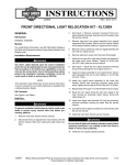
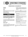
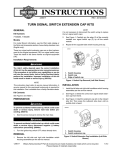
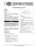
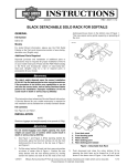
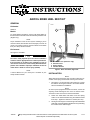
-J02180
REV. 2013-11-01
AIRFOIL RIDER HEEL REST KIT
GENERAL
is08164
Kit Number
50281-01
1
Models
For model fitment information, see the P&A retail catalog or
the Parts and Accessories section of www.harley-davidson.com
(English only).
NOTE
Proper installation of this kit also requires installing a pair of
Airfoil Foot Rests, Part Number 50133-95 (large) or 50134- 95
(small), not included in this kit. Airfoil Foot Rests are available
from your Harley-Davidson Dealer.
4
2
3
Kit Contents
See Figure 3 and Table 1.
The rider's safety depends upon the correct installation
of this kit. Use the appropriate service manual procedures.
If the procedure is not within your capabilities or you do
not have the correct tools, have a Harley-Davidson dealer
perform the installation. Improper installation of this kit
could result in death or serious injury. (00333a)
1.
2.
3.
4.
Figure 1. Stock Foot Rest, Right Side
NOTE
A Service Manual for your motorcycle is available at your
Harley-Davidson Dealer.
Rear brake lever (reference only)
Stock foot rest
Spring washer
Footrest bracket
INSTALLATION
NOTE
When performing the following step, note the location and orientation of the spring washer when removing each footrest.
1.
See Figure 1. On the right side of the motorcycle, remove
the fastener securing the footrest to the footrest bracket.
Save the hardware for installation.
NOTE
On motorcycles equipped with Airfoil Foot Rests, remove the
adjusting screw fastening the foot rest to its footrest mount.
Save the foot rest and screw for heelrest installation.
-J02180
2.
Fasten the Airfoil Rider Heel Rest mount and spring
washer to the footrest bracket using the hardware saved
from step 1. Tighten the fastener to 19 ft-lbs (26.7 Nm).
3.
See Figure 2 and Figure 3. Place the right-side Airfoil Rider
Heel Rest on the Airfoil Rider Heel Rest mount, positioning
the heelrest at the desired angle.
Many Harley-Davidson® Parts & Accessories are made of plastics and metals which can be recycled.
Please dispose of materials responsibly.
1 of 3
NOTE
Position the Airfoil Rider Heel Rest mount with the rounded
side of the mount facing upward in the footrest bracket. This
allows the assembly to fold upward for storage.
is08165
1
5
2
4.
Fasten the Airfoil Heel Rest to the mount using the nut
provided in this kit. Apply Loctite® 243 (blue) to the large
threads on the heel-rest mount and tighten the nut to 100
ft-lbs (135.5 Nm) torque.
5.
Fasten the right-side Airfoil Foot Rest to the Airfoil Rider
Heel Rest mount using the Airfoil Foot Rest adjusting
screw. Tighten the adjusting screw to 29 ft-lbs (39.3 Nm).
6.
Repeat steps 1 through 5 for the left-side footrest
assembly.
NOTE
At any time after installation, the Airfoil Foot Rest and Airfoil
Rider Heel Rest can be adjusted for riding comfort. Loosen the
nut on the Airfoil Rider Heel Rest mount to adjust the angle of
the heel rest. Loosen the Airfoil Foot Rest adjusting screw to
adjust the angle of the foot rest. Tighten the fasteners as
described above.
3
SERVICE PARTS
4
1.
2.
3.
4.
5.
Airfoil heel rest mount (rounded side up)
Foot rest adjustment screw
Airfoil heel rest nut
Airfoil heel rest
Spring washer
Figure 2. Airfoil Heel and Foot Rest Installed, Right Side
is08166
1
2
3
2
1
4
5
5
4
Figure 3. Service Parts
-J02180
2 of 3
Table 1. Service Parts
Item
Description (Quantity)
Part Number
1
Nut (2)
7745
2
Heel rest (2)
50283-01
3
Heel rest mount (2)
50282-01
4
Rubber kit
50925-01
5
Screw (4)
1627
-
Pin, rubber alignment (not shown)
50284-01
-J02180
3 of 3