1
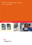
IVAC® Variable Pressure Volumetric
Pump (Models 571 and 572)
Technical Service Manual
s
This manual has been prepared for use by qualified service personnel only.
CareFusion cannot accept any liability for any breakdown or deterioration in performance of
parts or equipment resulting from unauthorised repair or modification.
Authorised EU Representive:
CareFusion,
The Crescent,
Jays Close,
Basingstoke,
Hampshire
RG22 4BS,
United Kingdom
IVAC® is a registered trademark of
CareFusion or one of its subsidiaries
All other trademarks belong to their respective owners.
© 1994 - 2010 CareFusion Corporation or one of its subsidiaries. All rights reserved.
IVAC® Volumetric Pump (Models 571 & 572)
2/104
1000SM00018 Issue 3
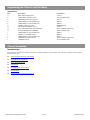
Contents
Chapter 1 Introduction & Start Up
4
Chapter 2 Configuration & Calibration
13
Chapter 3 Routine Maintenance
22
Chapter 4 Troubleshooting
37
Chapter 5 Circuit Descriptions
43
Chapter 6 Spare Parts Replacement Procedures
47
Appendix A Specifications
83
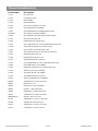
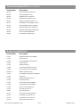
Appendix B Spare Parts Listing
89
Appendix C Configured Options 97
Appendix D Disposal
99
Appendix E Service Contacts
101
Appendix F Document History
103
Chapter 1
Introduction and Start Up
In this chapter
Introduction
5
General Precautions
6
Views of Models 571 and 572
6
Controls and Indicators
8
Loading the IV Infusion Set
9
Starting the Pump
9
Programming
10
Operating on Battery Power
10
Secondary Infusion (Model 572)
11
Flow Sensor
12
Pole Clamp Accessories
12
Introduction
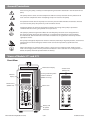
The IVAC® Volumetric Pump - Models 571 and 572 automatically regulates the infusion rate of IV solutions using a linear
peristaltic, volume displacement mechanism to regulate fluid flow at the prescribed rate. The pump can be operated with
a Flow Sensor and is compact and robust enough for most patient situations.
The IVAC® 571 Volumetric Pump operates in primary infusion mode only.
The IVAC® 572 Volumetric Pump has a primary and secondary infusion mode.
Product Familiarity
Ensure that you are fully familiar with the pump by carefully studying the Directions for Use (DFU) prior to operation and
prior to attempting any repairs or servicing. As part of continuous improvement, product enhancements and changes are
introduced from time to time.
Purpose of this Manual
This Technical Service Manual describes how to set up, test and maintain the following IVAC® Volumetric Pumps:
Model 571
Model 572
This manual is intended for use by personnel experienced in medical equipment testing and maintenance procedures.
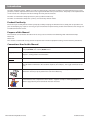
Conventions Used in this Manual
BOLD
Used for Display messages/values, self-test codes, controls and indicators referenced in this manual, for
example, CAL RATE, test code 11, ON/OFF switch.
'Single quotes'
Used to indicate cross-references made to another section of this manual. For example, see
Chapter 2, 'Configuration and Calibration'.
underline
Used to indicate a link to another section within this manual.
Italics
Used to refer to other documents or manuals. For example, refer to the relevant Directions for Use
(DFU) for further information. Also used for emphasis, for example, ...if the gap still measures less
than...
Wherever this symbol is shown a Hints & Tips note is found. These notes provide useful advice or
information that may help to perform the task more effectively.
Wherever this symbol is shown a Toolbox note is found. These notes highlight an aspect of test
or maintenance that is important to know about. A typical example is drawing attention to a
software upgrade that you should check has been installed.
IVAC® Volumetric Pump (Models 571 & 572)
5/104
1000SM00018 Issue 3
General Precautions
Prior to using this pump, carefully read the Operating Precautions described in the Directions for Use
(DFU).
This pump contains static-sensitive components. Observe strict precautions for the protection of
static sensitive components when attempting to repair and service the pump.
An explosion hazard exists if the pump is used in the presence of flammable anaesthetics. Exercise
care to locate the pump away from any such hazardous sources.
Dangerous Voltage. An electrical shock hazard exists if the casing of the pump is opened or
removed. Refer all servicing to qualified service personnel.
M
C
IV
d
This pump is protected against the effects of radio frequency emissions and is designed to be
fail safe if extremely high levels of interference are encountered. Should false alarm conditions
be encountered, either remove the source of the interference or regulate the infusion by another
appropriate means.
If the pump is dropped, subjected to excessive moisture, humidity or high temperature, or otherwise
suspected to have been damaged, remove it from service for inspection by qualified service
personnel.
When connected to an external power source, a three-wire (Live, Neutral, Earth) supply must be
used. If the integrity of the external protective conductor in the installation or its arrangement is in
doubt, the pump should be operated from the battery.
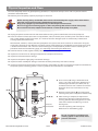
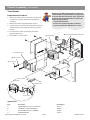
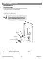
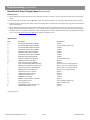
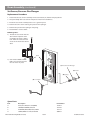
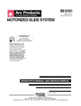
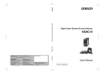
Views of Models 571 and 572
Front View
Information Display
Numeric
Display
Switch Panel
(Model 572)
Switch Panel
(Model 571)
Primary/Secondary/CRIS
Infusion Switches
(Model 572 only)
Door Latch
Battery and
AC power
Indicators
IVAC® Volumetric Pump (Models 571 & 572)
6/104
1000SM00018 Issue 3
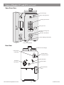
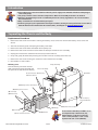
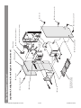
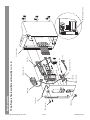
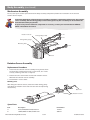
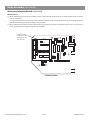
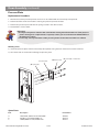
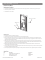
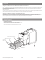
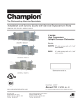
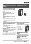
Views of Models 571 and 572 (continued)
Open Door View
Vacuum Plunger
Upper Tubing Retainer
Pumping Mechanism
Tubing Pincher
Pressure Sensing Disc
Retainer
Pressure Transducer
Lower Tubing Guide Posts
Air-In-Line Detector
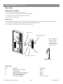
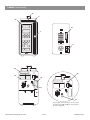
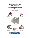
Rear View
Flow Sensor Storage
Flow Sensor
Connector
FLOW
SENSOR
Pressure Unit
Selector Switch
PE Connector
AC Power
Connector
Reset Switch
PUSH
TO
RESET
Test Connector
Cover
IVAC® Volumetric Pump (Models 571 & 572)
7/104
1000SM00018 Issue 3
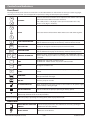
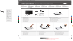
Controls and Indicators
Front Panel
The English switch panel controls and indicators are described below. For information on overlays in other languages,
refer to the relevant DFU. See also Appendix B, 'Spare Parts Listing' for switch panel part numbers.
UP/DOWN
Increases or decreases infusion rate and pressure and volume values. Three
columns for faster/slower increase or decrease:
Left = 100's, Centre = 10's, Right = units (or in micro mode Left = 10's,
Centre = units, Right = fractions).
CLEAR
Clears total volume infused when both switches are held down together.
TOTAL VOLUME INFUSED
Displays total volume infused value (primary + secondary volume infused).
Sets the Information Display to continuously monitor volume infused.
LIMIT
PRES
PRESSURE LIMIT
Displays or changes the occlusion pressure alarm level limit.
READ
PRES
READ PRESSURE
Displays the IV infusion site pressure.
Sets the Information Display to continuously monitor infusion pressure.
PRIMARY/SECONDARY
(Model 572 only). Switches between PRIMARY and SECONDARY infusion
modes. Allows displays of VTBI or rate setting of one mode while operating
in another.
CRIS
CRIS
On Model 572: only used in Self-test mode.
On Model 571: hidden switch, only used in Self-test mode.
RATE
RATE
Changes the infusion rate.
VOL
TO BE
INF
VOLUME TO BE INFUSED
(VTBI)
Sets the value of Volume To Be Infused. Displays volume remaining to be
infused.
RUN
HOLD
RUN/HOLD
Starts and stops pump infusion. Silences/cancels alarms and advances
start-up instruction messages.
ON/OFF
Turns the pump on and off.
AC POWER INDICATOR
When illuminated, indicates the pump is connected to an AC power supply
and the battery is being charged.
BATTERY INDICATOR
Flashes to indicate the pump is operating on battery power.
TOT
VOL
INF
TOT
VOL
INF
SEC
PRI
ON
OFF
0
With a Flow Sensor in use, an illuminated ("0") in the Information Display window indicates a drop is
detected by the flow sensor in the drip chamber.
Flashing Displays When the pump is operating on battery power, both Displays flash on/off.
Rear Panel
PUSH
TO
RESET
PRESSURE UNIT SELECTOR
SWITCH
Sets the displayed pressure units. Millimetres of mercury (mmHg) or
Centimeters of water (cmH20).
RESET SWITCH
Resets the circuit breaker.
IVAC® Volumetric Pump (Models 571 & 572)
8/104
1000SM00018 Issue 3
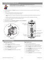
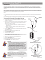
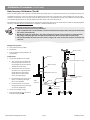
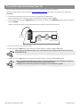
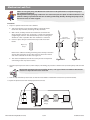
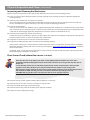
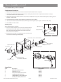
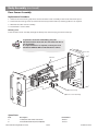
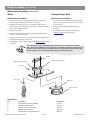
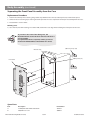
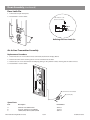
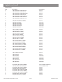
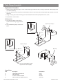
Loading the IV Infusion Set
Follow
Only
the Directions for Use supplied with the individual IV infusion set
use IVAC® "52" Series IV infusion sets
1. Prime the IV infusion set slowly ensuring all air is removed from the pressure disc then close the roller clamp.
2. Open the door.
3. Load the primed IV infusion set (see Figures 1-1 and 1-2):
Insert the set tubing into the upper tubing retainer.
Grasp the pressure sensor disc tabs between thumb and forefinger with the flat side (membrane) toward the
pump
Hook the pressure sensor disc under the disc retainer then press up and in to properly seat the disc
Place the tubing between the lower tubing guide posts.
4. Close and latch the door.
5. Open the roller clamp. Check drip chamber to ensure no fluid flows.
6. Connect to test equipment as required.
Upper Tubing
Retainer
Tubing Pincher
Pressure Sensing
Disc Retainer
Air-In-Line
Detector
Figure 1-1
Lower Tubing
Guide Posts
Figure 1-2
Starting the Pump
Without Flow Sensor
With Flow Sensor
1. Load the primed IV infusion set.
1. Load the primed IV infusion set.
2. Press the ON/OFF switch to power on the pump.
2. Connect the flow sensor to the drip chamber
ensuring the flow sensor is plugged into the pump.
3. Use the UP/DOWN switches (JK) to set the rate.
4. Press the RUN/HOLD switch to confirm.
3. Press the ON/OFF switch to power on the pump.
4. Use the UP/DOWN switches (JK) to set the rate.
5. Use the JK switches to set VTBI.
5. Press the RUN/HOLD switch to confirm.
6. Press the RUN/HOLD switch twice to start infusion.
6. Press VOL TO BE INF (if required) then use the
JK switches to set VTBI.
7. Press the RUN/HOLD switch twice to start infusion.
IVAC® Volumetric Pump (Models 571 & 572)
9/104
1000SM00018 Issue 3
Programming
Changing the infusion rate
1. Press the RUN/HOLD switch to place the pump on hold.
2. Press the RATE switch.
3. Use the JK switches to set the new rate.
4. Restart the pump at the new rate by pressing the RUN/
HOLD switch.
Clearing the total Volume Infused
1. Press the RUN/HOLD switch to place the pump on hold.
2. Press and hold the TOT VOL INF switch and the K
switch directly above simultaneously for 2 seconds until
display shows 000.0.
3. Resume infusion by pressing the RUN/HOLD switch.
Changing the Volume To Be Infused
1. Press the RUN/HOLD switch to place the pump on hold.
2. Press the VOL TO BE INF switch.
3. Set new volume by pressing the JK switches. OFF can
also be selected when a flow sensor is in use, see Notes
below.
4. Restart the pump by pressing the RUN/HOLD switch.
Notes:
1) Without a flow sensor in use, a VTBI value must be entered,
otherwise, the pump will be unable to operate.
2) With a flow sensor in use, a VTBI value isn't required and
OFF can be selected if required.
Adjusting the maximum pressure limit
(Occlusion pressure alarm level)
1. Simultaneously press and hold the LIMIT PRES
switch whilst using the JK switches to adjust
the pressure limit.
2. Release the LIMIT PRES switch.
Note: Pressure value will be displayed in mmHg or in
cmH20 depending on unit selected. See 'Pressure
Unit Selector'.
Reading the pressure
1. Press and hold the READ PRES switch. Wait at least
10 seconds to allow reading to stabilize.
Note: Pressure value will be displayed in mmHg or
in cmH20 depending on unit selected. See 'Pressure
Unit Selector'.
Selecting alternating display of total
volume infused
1. Press and release the TOT VOL INF switch three
times within 2 seconds while the pump is infusing or
on hold.
On Model 572, the display will alternate between
primary or secondary infusion and total volume
infused.
On Model 571, the display will continuously
show the total volume infused.
Selecting alternating display of infusion
pressure
1. Press and release the READ PRES switch three times
within 2 seconds while the pump is infusing or on
hold.
On Model 572, the display will alternate between
primary or secondary infusion and infusion
pressure.
On Model 571, the display will continuously
show the infusion pressure.
Operating on Battery Power
The pump operates on battery power when it is disconnected from the AC power. The battery power indicator, the
Information and Numeric Displays will flash whenever the pump is on battery power. In the event of a power failure, the
pump will automatically continue to operate on battery power.
Two alarms indicate the condition of the pump's battery:
LOW BATT alternating with the selected volume or pressure status. This indicates that approximately 30 minutes of
operating time remains on battery power
LOW BATT (constant). This indicates that the battery is discharged. Connect the pump to an AC power supply to
recharge the battery.
Note: The pump's battery is designed for limited duration use. Wherever possible, the pump should be used connected
to an AC power supply. If the pump is to be taken out of service for an extended period, it is good practice to charge the
battery periodically to ensure full capacity.
IVAC® Volumetric Pump (Models 571 & 572)
10/104
1000SM00018 Issue 3
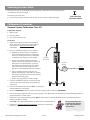
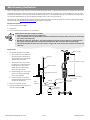
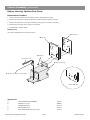
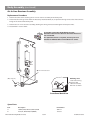
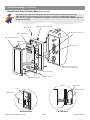
Secondary Infusion (Model 572)
Introduction
This mode of operation supports automatic secondary infusions ("piggybacking") in the same pump channel. When
the secondary VTBI reaches zero, a transition tone will sound and the primary settings will automatically take effect.
Secondary mode can be used where a second, independent VTBI is required, and also when an automatic rate change is
required.
When the pump is programmed and delivering in the secondary mode, the primary infusion is temporarily stopped and
fluid is drawn from the secondary (higher) container. Delivery from the primary container resumes when the fluid level in
the secondary line is level with the fluid in the primary container.
Notes:
1) The primary fluid container must hang lower than the secondary fluid container to allow the secondary infusion to
run.
2) On completion of the secondary infusion the pump will automatically return to primary infusion.
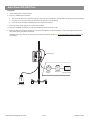
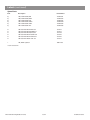
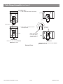
Starting the Pump with Secondary Infusion
1. Load the primed set. See 'Loading the IV Infusion Set' earlier in this
chapter for instructions.
Secondary
container
Primary
container
2. Prepare the secondary infusion using a secondary solution container
and the IVAC® "52" Series back check valve set; lower the primary
container. See Figure 1-3 below.
Prime the secondary IV infusion set in accordance with the set
Directions for Use
Attach a secondary IV infusion set to the upper Y-site of the
primary IV infusion set
3. Press the ON/OFF switch to power on the pump. Pump always starts
up in PRIMARY mode.
Back Check
valve
4. Use the JK switches to set the primary rate.
Y-Site
5. Press VOL TO BE INF if required.
6. Set primary VTBI if required.
7. Press the SEC switch to place the pump into SECONDARY mode. The
pump will sound a four beep verification tone.
8. Use the JK switches to set the secondary rate.
9. Press the VOL TO BE INF switch.
IV Infusion set
patient end
10.Set secondary VTBI by using the JK switches.
11.Press RUN/HOLD to start secondary infusion.
WARNING:
Secondary infusion applications using a back check
valve set must have a VTBI setting equal to the
volume in the secondary container; this will require
consideration of such variables as factory overfill,
medication additions, priming volume, etc.
Underestimating the volume will cause remaining
secondary solution to be infused at the primary rate;
overestimating will result in primary solution being
infused at the secondary rate.
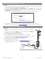
When using a flow sensor it must be positioned on the
primary IV infusion set (as shown in Figure 1-4). Correct
placement of a flow sensor is essential for proper
operation.
IVAC® Volumetric Pump (Models 571 & 572)
11/104
Figure 1-3
Secondary Infusion Set Up
Flow
Sensor
Figure 1-4
Secondary Infusion Set Up
with Flow Sensor
1000SM00018 Issue 3
Secondary Infusion (Model 572) continued
Additional Programming during Secondary Infusion
Verifying a value in one mode while operating in another
1. Press and release the appropriate (current) mode switch. For example, SEC.
2. Within two seconds press the switch representing the information to be displayed. For example, PRI.
Changing the infusion manually to primary mode
1. Press the RUN/HOLD switch to set pump on hold.
2. Press the PRI switch; pump sounds a three beep verification tone and goes into PRIMARY mode.
Flow Sensor
A flow sensor (part number 180) is used to detect an empty solution container. It is connected to the drip chamber and
when a drop is detected in the drip chamber an illuminated ("0") appears in the Information Display.
When not in use, the flow sensor can be stored on the pump handle.
Pole Clamp Accessories
The following pole clamp accessories allow the pump to be mounted on conventional IV poles:
Universal Pole Adapter (part number 5767C)
Pole Adapter (part number 5767A)*
Pole Clamp Accessory (part number BC100A)*
* must be used in conjunction with each other.
Refer to Chapter 6, 'Spare Parts Replacement Procedures' for assembly information.
IVAC® Volumetric Pump (Models 571 & 572)
12/104
1000SM00018 Issue 3
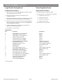
Chapter 2
Configuration & Calibration
In this chapter
Self-Test Mode
14
Mode Select Jumper
15
Configuration Settings
15
Selecting Pressure Units
17
Calibration Procedures
17
Self-Test Mode
Self-test mode is used to access a number of configuration and test routines which are designed to test and verify many
of the pump functions, defaults and calibrations without requiring internal inspection. Configuration settings are also
accessed via self-test mode.
Each test is accessed by selecting a Test ID number as shown in the table below.
Entering Self-Test Mode
Test ID
Description
001
Software Revision Display
002
Configuration Status Display
003
Flash Display Test
004
Segment Display Test
005
Sequence Display Test
006
EEPROM Test and Data Display
007
A/D Channels Test
008
Rate Calibration Display/Set
009 *
Configuration Rate Display/Set
010
Maximum Rate Display/Set
011 *
VTBI Configuration Display/Set
012
Pressure Display
013
Pressure Calibration Set
014
Maximum Occlusion Pressure Limit Display/Set
015
Default Occlusion Pressure Limit Display.Set
016
Alarm History Display/Clear
017
Switch Test
018
AC Power Run Time Display/Reset
019
Battery Run Time Display/Reset
1. After selecting the Test ID number (see above),
press the RUN/HOLD switch to start the test.
020
Secondary Mode Completion Tone Display/Set
2. To exit a test, press the RUN/HOLD switch.
021
Air-In-Line Test
022
I/O Port Test
Exiting Self-Test Mode
023
Language Display/Set
Self-test mode can be exited at any time:
024
CIM ID Display/Set
025
Alarm Tone Display/Set
026*
AIL Alarm Threshold Display/Set
027
System Vacuum Display
028
Enter Operational Setup Mode
029
Burn-In Test
030
Not used
031*
Infusion Mode Configuration Display/Set
1. Press the RUN/HOLD and ON/OFF switches
simultaneously until the display turns on. Initially,
the current software revision level is displayed.
2. Press the RUN/HOLD switch. The Information
Display will read: TEST ID and the Numeric
Display will read: 002 which means the pump is
ready to start test 002.
Note: The display may bypass the display of the
software revision level and advance directly to
TEST ID 002, depending on how long the RUN/
HOLD switch is held down.
3. Use the J K switches to select the Test ID
required.
The three columns of J K switches
allow faster/slower increments:
Left = 100's
Centre = 10's
Right = Units
Test Execution
Turn the pump off by pressing the ON/OFF switch
OR
Select test 028 then press the RUN/HOLD switch
to enter the start-up mode of operation
* A mode select jumper (part number 132350) must be
used to change settings, see 'Mode Select Jumper' for
further details.
IVAC® Volumetric Pump (Models 571 & 572)
14/104
1000SM00018 Issue 3
Mode Select Jumper
In order to perform certain tests and to change any pump settings, a mode select jumper must be installed.
Procedure:
1. With the pump off, remove the test connector cover from the back of the rear case.
2. Connect the mode select jumper (part number 132350) to the test connector, orientating the jumper so that CR1 is at
the top.
3. Place the pump in self-test mode then select and carry out the test(s) as required.
4. When the test is complete, switch the pump off and remove the mode select jumper from the test connector.
5. Refit the test connector cover.
Configuration Settings
Enter Self-Test mode. See 'Entering Self-Test Mode' in previous section for instructions.
Note: For default settings refer to Appendix C 'Configured Options'.
Test ID
009
010
011
014
Setting
Rate Configuration
RATE CFG
Maximum Rate
MAX RATE
VTBI Configuration
VTBI CFG
Maximum Occlusion
Pressure
MAXIMUM
IVAC® Volumetric Pump (Models 571 & 572)
Action/Data Displayed
Display and/or set the current rate range.
STANDARD = rate range of 001 to 999 ml/h
ALL RATE = rate range of 0.1 to 999.9 ml/h. Note: Use this setting where
fractional flow rates are required.
To change the setting:
Install the mode select jumper. See 'Mode Select Jumper'.
Press the CRIS (lower hidden switch on Model 571) and VOL TO BE INF
switches together and wait for a click.
Press the J unit (right column) switch to select STANDARD or the K unit
switch to select ALL RATE.
Display and/or set the maximum infusion rate.
999 = set to STANDARD rate configuration (ml/h). This rate cannot be changed.
0.1 and 999.9 = set to ALL RATE configuration (ml/h).
Note: Rate configuration is set in Test 009.
To change the maximum rate setting (for ALL RATE configuration):
Press and hold the PRI (upper hidden switch on Model 571) while using the
J K switches to adjust the value.
Display and/or set the Volume To Be Infused (VTBI) limit. VTBI limit ranges are:
MACRO = 1 to 9999 ml, MICRO = 0.1 to 999.9 ml.
If set to ALL RATE configuration (see Test 009), VTBI CFG can be set to MACRO
or MICRO.
If set to STANDARD rate configuration, VTBI CFG is set to MACRO and is not
adjustable.
To change the VTBI limit (for ALL RATE configuration):
Install the mode select jumper. See 'Mode Select Jumper'.
Press the CRIS (lower hidden switch on Model 571) and VOL TO BE INF
switches together and wait for a click.
Press the J unit switch to select MACRO or the K unit switch to select
MICRO.
Display and/or set the maximum occlusion pressure limit. Pressure values are
displayed in MMHG or CMH20 depending on the pressure units selected. See
'Selecting Pressure Units' for further information.
This pressure limit setting determines the upper limit of the pumps' variable
pressure range thereby fixing the upper limit when the LIMIT PRES switch is
used during normal operation.
To change the setting:
Press and hold the PRI (upper hidden switch on Model 571) while using the
J K switches to adjust the value.
Press the RUN/HOLD switch to save the new value.
15/104
1000SM00018 Issue 3
Configuration Settings (continued)
Test ID
015
Setting
Default Occlusion
Pressure
DEFAULT
020
Secondary Mode
Completion Tone
(Model 572 only)
023
024
025
026
031
Language
CIM ID
CIM ID
Alarm Tone
AIL Alarm Threshold
UL AIR
Infusion Mode
INFM CFG
IVAC® Volumetric Pump (Models 571 & 572)
Action/Data Displayed
Display and/or set the default pressure limit.
Pressure values are displayed in MMHG or CMH20 depending on the pressure
units selected. See 'Selecting Pressure Units' for further information.
This setting determines the occlusion pressure limit at power up.
To change the setting:
Press and hold the PRI (upper hidden switch on Model 571) while using the
J K switches to adjust the value.
Press the RUN/HOLD switch to save the new value.
Display and/or set the audible tone that sounds when the SECONDARY infusion
finishes and switches to PRIMARY infusion.
1 CLICK = one-click tone
4 BEEPS = four-beeps tone
To change the setting:
Press the J unit switch to select 4 BEEPS or the K unit switch to select 1
CLICK.
Display and/or set the language to be displayed. Languages are ENGLISH,
DUTCH, FRENCH, GERMAN, ITALIAN, SPANISH or SWEDISH.
To change this setting:
Press the J K unit switches to scroll through list and select language.
Setting is not in use. OFF = CIM not in use, 001 to 999 = CIM ID number
Important: Ensure the setting is OFF.
To change setting to OFF:
Press and hold the VOL TO BE INF switch while using the J K switches to
select OFF.
Press the RUN/HOLD switch to save the new setting.
Display and/or select the alarm tone volume level.
Approximate decibel volumes are:
HI TONE = 90 db
MED TONE = 80 db
LOW TONE = 70 db
To change the setting:
Press the J unit switch to select alarm tone.
WARNING: Take any necessary precautions against prolonged exposure to the
HI TONE alarm as this may result in hearing damage.
Display and/or set the air bubble length maximum value. This value is the
nominal air bubble threshold in microlitres used for air-in-line detection. Value
must be between 50 and 150 microlitres.
To change the setting:
Install the mode select jumper. See 'Mode Select Jumper'.
Press the CRIS (lower hidden switch on Model 571) and VOL TO BE INF
switches together and wait for a click.
Press the J K switches to enter the value (in 10 µl increments).
Display and/or set the pump infusion mode.
PRI ONLY = PRIMARY infusion mode only (Model 571).
SEC/CRIS = PRIMARY and SECONDARY infusions modes. (Model 572).
To change the setting:
Install the mode select jumper. See 'Mode Select Jumper'.
Press the CRIS (hidden switch on Model 571) and VOL TO BE INF switches
together and wait for a click. Press the J unit switch to select PRI ONLY or
the K unit switch to select SEC/CRIS.
Note: Model 571 must be set to PRI ONLY.
16/104
1000SM00018 Issue 3
Selecting Pressure Units
The pressure units can be configured to be displayed as millimetres of mercury (mmHg) or
as centimeters of water (cmH20).
To select the pressure units:
Pressure Unit
Selector Switch
Set the Pressure Unit Selector switch on the rear panel to the required position.
Calibration Procedures
Vacuum System Calibration (Test 27)
Equipment required:
50ml
syringe
Pressure
"52"
gauge
Series IV infusion set
Procedure:
1. Remove the battery cover from the pump to
allow access to the Accessory Interface Board.
See Chapter 6, 'Spare Parts Procedures' for
instructions.
2. Prepare a modified IV infusion set as follows:
Completely
remove the clear membrane
cover from the white pressure sensing disc.
Ensure no membrane remains as this could
compromise the integrity of the vacuum
Attach
the air-filled IV infusion set to the
syringe. Use the luer fitting on the distal end
of the set or cut approximately 1 inch (2.5
cm) off the distal end and press the tubing
firmly into the tip of the syringe. Ensure a
good seal is formed between the two devices
Proximal
End of Set
Pressure
Gauge
Syringe
Splice
a T-fitting into the IV infusion set
tubing approximately 1 foot (30 cm) up from
the syringe attachment. Connect the pressure
gauge to the T-fitting port
Push
the syringe plunger in until it stops
3. Load the modified IV infusion set into the pump
and close the door. Ensure that the set tubing is
not kinked.
4. Enter self-test mode and select test 027. See 'Entering
Self-Test Mode' for instructions.
5. Press the RUN/HOLD switch to enter the Vacuum Display mode and display VAC MMHG.
6. Pull the syringe plunger out until the pressure gauge reads -95 mmHg and immediately clamp off tubing below the
pump to hold the vacuum stable.
7. Adjust the vacuum detect potentiometer R45 on the Accessory Interface Board until the numeric display on the
pump reads -95 ± 5 mmHg.
Note: R45 is the upper potentiometer on the Accessory Interface Board.
8. Perform the 'Vacuum Retention Verification' procedure as detailed in
Chapter 3, 'Routine Maintenance'.
IVAC® Volumetric Pump (Models 571 & 572)
17/104
Do not adjust the lower
potentiometer, R4, this
is pre-adjusted during
manufacture.
1000SM00018 Issue 3
Calibration Procedures (continued)
Dry Set Pressure Calibration (Test 13)
Equipment required:
Test
jumper cable (142109)
Pressure
"52"
gauge
Series IV infusion set (dry set)
Procedure:
1. Remove the chassis from the body. See Chapter 6, 'Spare Parts Procedures' for instructions.
2. Attach the jumper of the test jumper cable between connector J7 on the Logic Board and connector P7 on the
Accessory Interface Board.
3. Connect the battery pack to the battery connector.
4. Set up equipment as shown below.
Note: Set the pressure unit selector switch (on the back panel of the pump) to the same units as the air pressure
source.
Proximal
End of Set
V
Pressure
Gauge
Reservoir
Air
Pressure Source
5. Enter self-test mode, press the RUN/HOLD switch and select test 12. Press the RUN/HOLD switch again to display the
pressure MMHG (or CMH20).
Ensure the pump is connected to the AC power supply for approximately 30 minutes before continuing with this
calibration.
6. Enter self-test mode, press the RUN/HOLD switch and select test 13. Press the RUN/HOLD switch again to display
PRES CAL.
7. With the door open and no set loaded, adjust the zero potentiometer (R20 on the Analog Board) so the pump reads
000 ±1 mmHg (or 000 ±1.4 cmH20).
8. Install an IV infusion set, close the door and apply a test pressure of 000 mmHg (000 cmH2O) to the distal end of the
set. Record the reading displayed as the PI offset value.
9. Apply a test pressure until the meter reads 400 mmHg (544 cmH2O) and adjust the span potentiometer (R23 on the
Analog Board) so the pump reads 400 mmHg ±2 (544 cmH20 ±10 ) plus the offset value, PI, recorded in the previous
Step.
10.Return the test pressure to 000 mmHg (000 cmH2O), bleed off any air from the IV infusion set then remove the IV
infusion set.
Note: If the set is removed when still under pressure may result in damage to the pressure sensing disc film.
11.Leave the door open and reverify that the pump reads 000 ±1 mmHg (000 ±1.4 cmH2O). If not, repeat the procedure
from Step 7, until no further adjustment of the zero and span potentiometers is required.
IVAC® Volumetric Pump (Models 571 & 572)
18/104
1000SM00018 Issue 3
Calibration Procedures (continued)
Dry Set Pressure Calibration (Test 13) continued
12.Press the J unit and RATE switches simultaneously for a minimum of one second to set the 000 mmHg (000 cmH2O)
calibration point.
13.Reload the IV infusion set and apply test pressure until the meter reads 400 mmHg (544 cmH2O). When the pressure
reading is stable, press the TOT VOL INF and the J 100 switches simultaneously for a minimum of one second to set
the 400 mmHg (544 cmH2O) calibration point.
Both Steps 12 and 13 must be performed to correctly set the calibration parameters. Performing
only one step will result in the message RECONFIG REQD when the pump returns to operation.
14.Press the RUN/HOLD switch to return to test 13 and turn the pump OFF. Remove the IV infusion set (first bleeding off
any pressure).
15.Disconnect the battery pack from the battery connector.
16.Remove the test jumper cable and reassemble the pump.
17.Perform the 'Dry Set Pressure Verification' procedure as detailed in Chapter 3, 'Routine Maintenance'.
IVAC® Volumetric Pump (Models 571 & 572)
19/104
1000SM00018 Issue 3
Calibration Procedures (continued)
Rate Accuracy Calibration (Test 8)
There are two types of rate accuracy associated with the pump, these are System Rate Accuracy and Pump Rate Accuracy.
System Rate Accuracy is the rate accuracy of the pump when used with a standard "52" Series infusion set. Due to slight
variations in between sets, the system accuracy of the pump is ± 5%. Pump Rate Accuracy is the absolute rate accuracy of
an individual pump which can only be determined with the use of a characterised set.
The following procedure describes how to calibrate the Pump Rate Accuracy. For instructions on how to verify Pump Rate
Accuracy, see 'Rate Accuracy Verification' in Chapter 3, 'Routine Maintenance'.
Characterised Sets (part number 191806)
Must be used for rate accuracy calibration
Sets are labeled with a serial number, a nominal volume and an expiry date (180 days from the date
the set was characterised)
Handle sets with care at all times. Sets must not be pressurised. Prior to loading or removing from
the pump, manually open the auto-pinch-off mechanism. Do not stretch the set excessively
Record the number of times each set is used in a log book. A set must not be used for more than 20
rate runs.
Equipment required:
Characterized
set (191806)
Stopwatch
Water Source
Class
A burette (50 ml) with 0.1 ml
graduations
Burette
Preparation:
1. Set up the equipment as shown.
34 ± 4 inches (86 ± 10 cm)
The
vertical distance from the
fluid level of the container to
the pump pressure transducer
should be 34 ±4 inches
Burette Clamp
The
burette zero line should
be within ± 2 inches from the
pump pressure transducer.
Verify that the inside of the
wall is free of droplets
fittings are secure and
there is no leakage through
the 3-way stopcock
Equipment Stand
Pressure Transducer
(level with)
Ensure
Ensure
that the air has been
purged from the characterised
set and all equipment
Three-way
Stopcock
Tubing
Table
or Bench
Set Tubing
Used Fluid
Recptacle
2. Close the set roller clamp.
3. Plug the pump into the AC mains
and turn the pump ON.
IVAC® Volumetric Pump (Models 571 & 572)
20/104
1000SM00018 Issue 3
Calibration Procedures (continued)
Procedure:
1. Enter self-test mode, press the RUN/HOLD switch and select test 8. Press the RUN/HOLD switch again to display CAL
RATE.
2. Press and hold the PRI switch then use the JK switches to enter an initial rate calibration of 37. Press the ON/OFF
switch to turn the pump off.
Note: Ensure a characterised set is loaded and the burette is free of droplets.
3. Turn the pump ON and set the pump to Primary rate = 800 ml/h, VTBI = OFF, TOT VOL INF = 000.0 (or, if not using a
flow sensor, set the pump to Primary rate = 800 ml/h, VTBI = 100 ml, TOT VOL INF = 000.0).
4. Press the RUN/HOLD switch to start the pump and simultaneously start the stopwatch. Allow the pump to run for 3
minutes (180 seconds) then press the RUN/HOLD switch to put the pump on hold.
5. Verify that the volume in the burette is 40.0 ± 0.4 ml. If not, repeat the test.
If the percentage of error is greater than ± 1%, use the following formula to determine the new CAL RATE number:
Formula to determine new CAL RATE number
Final CAL RATE number =
[
(actual volume)
-1 ) x 200
expected volume
]
+ initial number
Example:
actual burette volume
= 40.8 ml
expected volume
= 40.0 ml
initial CAL RATE number
= 37
Final CAL RATE number =
[
(40.8)
-1 ) x 200
40.0
]
+ 37
= 41
Set the CAL RATE number to 41 in Test 8 while pressing the PRI switch.
6. Repeat the above calibration procedure until the actual volume is within ±1% of the expected volume indicated on
the characterised IV infusion set.
IVAC® Volumetric Pump (Models 571 & 572)
21/104
1000SM00018 Issue 3
Chapter 3
Routine Maintenance
In this chapter
Routine Maintenance
23
Self-Test Functions
23
Upgrading Software
26
Vacuum Retention Verification (Test 27)
26
Dry Set Pressure Verification (Test 12)
27
Functionality Checks
28
Auto-Pinch-Off (APO) Test
29
Mechanism Leak Test
30
Rate Accuracy Verification
32
Downstream Pressure Occlusion Test
33
Physical Inspection and Clean
34
Inspecting the Mechanism
35
Flow Sensor Check (where flow sensor is in use)
35
Performance Verification Procedure
36
Routine Maintenance
For routine maintenance, the following tests and procedures should be performed in addition to the tasks described in
the section 'Physical Inspection and Clean'.
Refer to the relevant DFU for the recommended routine maintenance period.
Self-Test Functions
The self-test functions are a series of test routines which are designed to test and verify many of the pump functions and
defaults without requiring internal inspection. These tests are accessed by entering Self-Test mode and selecting a Test ID
number as shown in the table below.
1. Enter Self-Test mode. See 'Entering Self-Test Mode' in Chapter 2 for instructions.
2. Proceed through the series of tests, referring to the table below for details of each test.
Note: For details of other tests such as the configurable options and calibration settings, see Chapter 2, 'Configuration
& Calibration'.
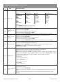
Test
ID
Test
001
Software
Revision
Displays the current software revision level, e.g. REV 3.01.
Configuration
Status
Verifies whether or not the configuration data is valid.
CONFIG/VALID = configuration data is valid
OR,, where not valid, a message indicates which configuration is required to be set:
SET RATE CAL = see Test ID 008
SET RATE CONFIG = see Test ID 009
SET RATE MAX = see Test ID 010
SET VTBI CONFIG = see Test ID 011
SET PRES CAL = see Test ID 013
SET PRES MAX = see Test ID 014
SET PRES DEFAULT = see Test ID 015
SET AIR LIMIT = see Test ID 026
SET INF MODE CONFIG = see Test ID 031
Display Flash Test
Verify that the segments of both Displays light and the battery indicator flashes as follows:
Information Display: all positions show ******** alternating with 00000000.
Numeric Display: all positions show 8888 alternating with 0000. The two decimal points also
flash.
Battery indicator: flashes alternately on and off.
Display Segment
Test
Verify that both Displays show various characters and the battery indicator flashes as follows:
Information Display: repeatedly cycles through the 64-character set (A to Z, 0 to 9 and ASCII
characters). All positions must show the same character at the same time.
Numeric Display: repeatedly cycles through numbers 0 to 9. All positions must show the same
character at the same time.
Battery indicator: flashes alternately on and off.
005
Display
Sequence Test
Verify that both Displays show numbers, one position at a time (and the battery indicator
flashes) as follows:
Information Display: numbers 0 to 7 appear sequentially, left to right.
Numeric Display: numbers 0 to 3 appear sequentially, left to right.
Battery indicator: flashes alternately on and off.
006
EEPROM Test and
Display Data
Verify that both Displays cycle through numeric sequences (and the battery indicator flashes)
as follows:
Information Display: ignore this 128-byte location reading.
Numeric Display: counts from 001 through 128.
002
003
004
Action/Description
IVAC® Volumetric Pump (Models 571 & 572)
23/104
1000SM00018 Issue 3
Self-Test Functions (continued)
Test
ID
Test
Action/Description
Verify the eight A/D channels (0 through 7) as follows, using the J and K switches to select
each channel.
Note: The Information Display shows the Channel number being tested (0 through 7) and the
Numeric Display shows a value representing the analog input to the A/D convertor.
Channel 0 = Flow Sensor Test
Information Display: All positions show 0's, 00000000.
Numeric Display: Value must be greater than 195 (no obstruction in the light path), or less
than 185 (light path is obstructed).
Channel 1 = Drop Reference
Information Display: All positions show 1's, 11111111.
Numeric Display: Value must read 210 ± 8.
007
A/D Converter
Test
Channel 2 = Battery Monitor
Unplug the pump from AC power.
Information Display: All positions show 2's, 22222222.
Numeric Display: New battery reading must be greater than or equal to 140. A reading of less
than 140 indicates a discharged or bad battery.
Plug the pump into AC power.
Channel 3 = Pressure
Information Display: All positions show 3's, 33333333.
Numeric Display: value between 0 and 500.
Channel 4 = Flow Sensor Detect
Information Display: All positions show 4's, 44444444.
Numeric Display: Value less than 20 (flow sensor not plugged in) or more than 80 (flow sensor
plugged in).
Channel 5 = Vacuum Detect Signal
Information Display: All positions show 5's, 55555555.
Numeric Display: Value between 110 and 277 (with set installed).
Channel 6 = Not used. Ignore reading.
Channel 7 = Not used. Ignore reading.
012
016
Read Pressure
Verify the pressure level reading sensed by pressure transducer. Note: To ensure a valid
reading, the pump should be powered on for at least 30 minutes prior to this test.
Information Display: CMH20 or MMHG (per pressure unit selection switch position on back
panel).
Numeric Display: Without set installed, shows value between -28 and +14 cmH20 or between
-20 and +10 mmHg.
Read Alarm
History
Read the last 16 alarm or error messages (alarm stack).
The most recent alarm or error is always displayed first.
Information Display: All positions show *'s, ******** are displayed initially, followed by
repeated cycle of the last 16 alarm messages.
Numeric Display: Blank
To clear the alarm stack:
Press and hold the READ PRES switch and the J 100 switch for at least 2 seconds, until
the display shows ********.
IVAC® Volumetric Pump (Models 571 & 572)
24/104
1000SM00018 Issue 3
Self-Test Functions (continued)
Test
ID
Test
Action/Description
Information Display: Initially shows SWCH TEST. Press each switch and verify the
corresponding code is displayed:
017
Switch Test
Switch:
Display code:
Switch:
Display code:
TOT VOL INF
PRI
RATE
LIMIT PRES
SEC
VTBI
READ PRES
TL V INF
PRI
RATE
LIMT PRS
SEC
VTBI
READ PRES
CRIS
J 100
K 100
J 10
K 10
J Unit
K Unit
CRIS
UP 100
DN 100
UP 10
DN 10
UP 1
DN 1
Notes:
1) The ON/OFF switch does not have a code.
2) The Numeric Display remains blank.
018
019
021
022
027
Read Hours on
AC
Read/clear the total number of hours that the pump has run on AC power.
Information Display: AC HRS
Numeric Display: Number of hours on AC power.
To reset the total AC power hours to 0000:
Press and hold the READ PRES switch and the J 10 switch for at least 2 seconds.
Read Hours on
Battery
Read/clear the total number of hours that the pump has run on battery power.
Information Display: BATT HRS
Numeric Display: Number of hours on battery power.
To reset the total AC battery hours to 0000:
Press and hold the READ PRES switch and the J unit switch for at least 2 seconds.
Air-In-Line Test
Verify air-in-line sensor operation. To run test:
Load an air-filled or fluid-filled IV infusion set.
Information Display: 00000000 = fluid detected in IV infusion set and door is closed.
10000000 = air detected in IV infusion set or door is open.
Numeric Display: UAIL
I/O Port Test
Read data on the various input ports. Press the J and K switches to select each port.
Information Display: Shows the 8 input port data bits in binary format.
Numeric Display: Indicates which port is being examined:
000 = display port, Display U7. 008 = switch port, Display U5. 016 = Logic U20. 048 = A/D end
of conversion, U22. 064 = Logic U21. 080 and 081 = parallel I/F ports. 096, 097, 098 and 099
= serial I/F ports. 128 = timer of Logic U14. 129 = Logic U23. 130 = Logic U24.
Key troubleshooting tests:
Port 016
bit 0 = rotation sensor 1
bit 1 = rotation sensor 2
bit 2 = set sensor
bit 3 = air-in-line sensor
Port 064
bit 7 = door sensor
System Vacuum
Test
Read the vacuum level being applied by the vacuum system when an IV infusion set is loaded
and the door is closed.
Information Display: VAC MMHG
Numeric Display: Current vacuum value that is generated to hold the pressure sensing disc in
place.
To run the test, following the instructions in 'Vacuum Retention Verification' later in this
chapter.
IVAC® Volumetric Pump (Models 571 & 572)
25/104
1000SM00018 Issue 3
Self-Test Functions (continued)
Test
ID
Test
Enter
Operational
Setup Mode
028
029
Burn-in Test
Action/Description
The pump exits self-test mode and starts operational set up mode.
Allows pump to run (burn-in) without setting up an IV solution bag, fluid and drain.
Warning:
This test must only be run in a workshop environment for verification that internal failures have
been corrected. Full performance verification testing must then be carried out.
To run test: Load an air-filled IV infusion set and close the door. Enter self-test mode, select
test 029, press the RUN/HOLD switch then, within two seconds, press and hold the PRI and
CRIS switches together. Pump will start running at maximum rate and rate can be changed by
pressing the RATE switch and using the J and K switches.
Upgrading Software
The latest version of software available for Model 571/572 is V3.01. Perform upgrades by acquiring the software upgrade
kits specified in the spare parts listing.
Equipment required:
Software upgrade kit
Software Upgrade Kits Available
Pump Model
Software
Version
Part Number
145071
KIT,UPGRD,REV 3.01,570
(EPROM only)
3.01
145070
SERV ASSY,MEM,REV3.01,570(BOM)
(includes EPROM fitting and removal instructions)
3.01
571/572
Vacuum Retention Verification (Test 27)
The pump's vacuum system can be tested and verified by performing the following Vacuum Leak Test.
Procedure:
1. Enter self-test mode and select test 27. Press the RUN/HOLD switch to enter the Vacuum Display mode and display
VAC MMHG.
2. Load an IV infusion set and close the door.
3. Verify that the numeric display shows a reading of -250 or more negative.
4. Allow the reading to stabilise for 5 to 10 seconds, then record the value, for example, -337.
5. After 30 seconds, verify that the vacuum value has not decreased by more than 5, for example -332.
If the pump fails this test:
l Check the following things, replacing and repeating the test as necessary:
Face of the pressure transducer
Replace the test IV infusion set
Y-clip, door latch pin, door latch
Pressure transducer/vacuum assembly
l Perform the 'Vacuum System Calibration' procedure, see Chapter 2. for instructions.
IVAC® Volumetric Pump (Models 571 & 572)
26/104
1000SM00018 Issue 3
Dry Set Pressure Verification (Test 12)
When servicing the pump perform the following pressure calibration verification procedure.
Note: If the pump fails this test, perform the 'Dry Set Pressure Calibration' procedure. See Chapter 2. for instructions.
Procedure:
1. Connect the pump to the AC mains and set up the equipment as shown below..
Note: Set the pressure unit selector switch (on the back panel of the pump) to mmHg.
2. Enter self-test mode, press the RUN/HOLD switch and select test 12. Press the RUN/HOLD switch again to display the
pressure MMHG.
Allow the pump to warm up for approximately 30 minutes before continuing with this test.
Proximal
End of Set
C
Pressure
Gauge
Reservoir
Air
Pressure Source
3. Load an IV infusion set and close the door.
4. Apply a pressure of 000 mmHg and verify that the pump displays a reading of -20 to +10 mmHg.
When applying the 000 mmHg pressure, ensure the set has just been loaded. If necessary reload
the IV infusion set.
5. Apply a pressure of 400 mmHg and verify that the pumps displays a reading of 367 to 423 mmHg.
not allow the applied test pressure to exceed the intended pressure value by more than 50
mmHg. If this occurs, reload the IV infusion set and repeat test
The pressure read accuracy must be ±15 mmHg or ± 7%, whichever is greater
Do
IVAC® Volumetric Pump (Models 571 & 572)
27/104
1000SM00018 Issue 3
Functionality Checks
Alarms
Alarm
Action
LOAD SET
Without an IV infusion set loaded, turn the pump ON, set rate to 125 ml/h then press the RUN/HOLD switch.
Verify that the LOAD SET message is displayed.
DOOR
With the pump running, open the door. Verify that the pump stops, alarms and the message DOOR is
displayed. Verify that the automatic pinch-off clamp has stopped the flow by checking that no drops are
falling in the drip chamber.
Load a fluid-filled IV infusion set. Turn the pump ON, set rate to 125 ml/h then press the RUN/HOLD switch
to start infusing. Tilt the drip chamber of the set to induce air bubbles into the IV infusion set. Verify that
when the air bubble enters the pump, the pump alarms, stops and displays the message AIR IN LINE. Turn
the pump OFF and remove the test loop.
AIL
Load an empty, air-filled IV infusion set. Turn the pump ON then press the RUN/HOLD switch to start the
pump. The pump should not run; verify that the AIR IN LINE message is displayed. If the pump does run,
refer to Chapter 4, 'Troubleshooting'.
Block the light in the flow sensor (with a finger or other suitable object) to simulate a faulty flow sensor.
Press the RUN/HOLD switch to resume infusing. After a short time, verify that the pump stops, alarms and
the display message alternates between FLOW and SENSOR.
FLOW SENSOR
BOTTLE CLAMP
(with Flow Sensor)
UPSTREAM
OCCLUSION
(without Flow Sensor)
Press the RUN/HOLD switch to place the pump on hold. Hold the VOL TO BE INF switch and press the K
unit switch until OFF is displayed. Press the RUN/HOLD switch to start the infusion. After approximately one
minute, close the roller clamp. Verify that the pump stops running, the alarm tone sounds and the display
message alternates between BOTTLE and CLAMP.
Press the RUN/HOLD switch to place the pump on hold. Set VTBI to 60 ml by first pressing the VOL TO BE
INF switch then the J K switches. Set rate to 900 ml/h then press the RUN/HOLD switch to start
infusing. After approximately one minute, close the roller clamp to create an upstream occlusion.
Verify that the pump stops running, alarms and displays UPSTREAM OCCLUSION.
Press the RUN/HOLD switch to place the pump on hold. Verify that the pump takes 2 minutes ±10 seconds
to alarm after the last switch has been pressed. TIME OUT is displayed, and the rate is still shown.
TIME OUT
PRESSURE LIMIT
EXCEEDED
(DOWNSTREAM
PRESSURE
EXCEEDED)
See 'Downstream Pressure Occlusion Test' procedure later in this chapter for instructions.
Battery Power Check and Operation Test
Before performing this test, it is recommended that the battery is charged to full capacity by
connecting the pump to AC mains for a minimum of 16 hours.
1. Remove power cord from the AC power socket.
2. Press the ON/OFF switch to turn the pump on. Verify that the battery indicator flashes on and off.
3. Set rate to 499 ml/h then press the RUN/HOLD switch to start the pump. Verify that the pumping indicator bar
appears on the Information Display and that it rotates rapidly.
4. (Optional) Verify that the pump continues to run for a minimum of 15 minutes without alarming LOW BATT.
5. Plug the power cord back in to AC power socket.
Flow Sensor Check
See 'Physical Inspection and Clean' for instructions.
IVAC® Volumetric Pump (Models 571 & 572)
28/104
1000SM00018 Issue 3
Auto-Pinch-Off (APO) Test
Procedure:
1. Set up equipment as shown below.
2. Prepare a modified set as follows:
Take
an IV infusion set and cut the tubing a couple of inches below the drip chamber, discarding the drip chamber.
Connect
Insert
the air pressure source to the freshly cut proximal end of tubing.
the distal end of the modified set into a container of water.
3. Close the roller clamp. Adjust the air pressure to 10 psi.
4. Load the modified IV infusion set. Close the door then open the roller clamp.
5. Open the door and verify that (after an initial spurt of bubbles) no further bubbles are seen coming from the distal
end of the tubing into the water bottle.
If bubbles continue, replace the auto-pinch mechanism. Refer to Chapter 6, 'Spare Parts Replacement Procedures' for
instructions.
Roller Clamp
Pressure
Gauge
Reservoir
Air
Pressure Source
Water Bottle
IVAC® Volumetric Pump (Models 571 & 572)
29/104
1000SM00018 Issue 3
Mechanism Leak Test
When servicing the pump, the Mechanism Leak Test must be performed to verify the integrity of
the pumping mechanism.
Misalignment of the pumping mechanism can result in the pressure plate and the mechanism's cam
followers failing to pinch the IV infusion set tubing sufficiently, thereby allowing the pump to leak
fluid at low rates or when stopped.
Procedure:
1. Prepare a special Pressure Test Set as follows:
Take
an IV infusion set and cut the tubing a couple of inches
below the drip chamber, discarding the drip chamber.
With
a knife, carefully remove the membrane cover from the
white pressure sensing disc, see Figure 3-2. Ensure no membrane
(rough edges) remain—the surface of the pressure sensing disc
should be as flat as possible after the membrane is removed.
Firmly press
mylar cap
over slot
Cut away
membrane cover
Cut
out a piece of mylar to match the shape and size shown
below.
Mylar Cap
Shape
Remove the adhesive backing and firmly press the mylar onto the
surface of the pressure sensing disc so that it covers the vertical
slot and is centered on the disc. See Figure 3-3
The
distal end (bottom) end of the set may be cut to adapt it for
connecting to the air pressure source.
Figure 3-2
Figure 3-3
2. Load the special pressure test set, with 15.0 psi (775 mmHg) air pressure at the distal end, into the pump and close the
door.
Change the special Pressure Test Set after 20 uses, or if signs of wear are visible on the silicone
section or if any leak in the set is observed.
3. Run the top end of the pressure test set into the water bottle and below the water level (as shown below).
4. Open the pressure test roller clamp to pressurise the set.
Pressure
Gauge
Water Bottle
Reservoir
Air
Pressure Source
Roller Clamp
IVAC® Volumetric Pump (Models 571 & 572)
30/104
1000SM00018 Issue 3
Mechanism Leak Test continued
5. Verify that the pressure (that the transducer is seeing) is not greater than 300 mmHg when set is fully pressurised. To
do this read the pressure using test 12 (Enter self-test mode, press the RUN/HOLD switch and select test 12).
Warning: A pressure reading greater than 499 mmHg may result in damage to the transducer.
If a high pressure reading is noted, check the following:
The
pressure sensing disc is positioned correctly.
The
mylar cap is adhered tightly and correctly on the pressure sensing disc.
The
height of the mylar cap matches the Myler Cap Shape shown above.
6. Connect the pump to the AC mains then turn the pump ON, entering self-test mode.
7. Press the RUN/HOLD switch and select the burn-in test 29, then within two seconds, simultaneously press and hold
the PRI switch and the CRIS switch.
Verify that the pump is running at 999 (or 999.9 ml/h).
8. Set the rate to 20 ml/h (or 20.0 ml/h) by simultaneously pressing the RATE switch and the J K switches. Run the
pump for at least one minute. Verify that no bubbles are visible in the water bottle.
If air bubbles are visible in the water bottle, the pump fails the test.
If the pump fails the test, verify set up and repeat the test as required, otherwise, return the pump to the
manufacturer.
9. Turn the pump OFF.
10.Close the roller clamp slowly. Open the door to release any pressure trapped in the pressure test set and carefully
remove the set from the pump.
Note: Take care not to stretch the silicone segment of the set as correct segment length is critical to the mechanism's
pinch-off capabilities.
IVAC® Volumetric Pump (Models 571 & 572)
31/104
1000SM00018 Issue 3
Rate Accuracy Verification
There are two types of rate accuracy associated with the pump, these are System Rate Accuracy and Pump Rate Accuracy.
System Rate Accuracy is the rate accuracy of the pump when used with a standard "52" Series infusion set. Due to slight
variations in between sets, the system accuracy of the pump is ± 5%. Pump Rate Accuracy is the absolute rate accuracy of
an individual pump which can only be determined with the use of a characterised set.
The following procedure describes how to verify the Pump Rate Accuracy. For instructions on how to calibrate the Pump
Rate Accuracy, see 'Rate Accuracy Calibration' procedure in Chapter 2.
Equipment required:
Characterized
set (191806)
Stopwatch
Class
A burette (50 ml) with 0.1 ml graduations
Characterised Sets (part number 191806)
Must be used for rate accuracy calibration
Sets are labeled with a serial number, a nominal volume and an expiry date (180 days from the date
the set was characterised)
Handle sets with care at all times. Sets must not be pressurised. Prior to loading or removing from
the pump, manually open the auto-pinch-off mechanism. Do not stretch the set excessively
Record the number of times each set is used in a log book. A set must not be used for more than 20
rate runs.
Preparation:
Water Source
1. Set up the equipment as shown.
The
vertical distance from the
fluid level of the container to
the pump pressure transducer
should be 34 ±4 inches
Burette
34 ± 4 inches (86 ± 10 cm)
The
burette zero line should
be within ± 2 inches from the
pump pressure transducer.
Verify that the inside of the
wall is free of droplets
Burette Clamp
Ensure
fittings are secure and
there is no leakage through
the 3-way stopcock
that the air has been
purged from the characterised
set and all equipment
Equipment Stand
Pressure Transducer
(level with)
Ensure
2. Close the set roller clamp.
3. Plug the pump into the AC mains
and turn the pump ON.
IVAC® Volumetric Pump (Models 571 & 572)
Three-way
Stopcock
Tubing
Table
or Bench
Set Tubing
Used Fluid
Recptacle
32/104
1000SM00018 Issue 3
Rate Accuracy Verification (continued)
Procedure:
1. Set the pump to Primary rate = 800 ml/h, VTBI = OFF, TOT VOL INF = 000.0 (or, if not using a flow sensor, set the pump
to Primary rate = 800 ml/h, VTBI = 100 ml, TOT VOL INF = 000.0).
2. With the pump displaying START PRIMARY or ON HOLD PRIMARY, press the RUN/HOLD switch to start the pump
and simultaneously start the stopwatch. Allow the pump to run for 180 seconds (3 minutes) ± 0.5 seconds then press
the RUN/HOLD switch to put the pump on hold.
3. Measure the volume in the burette and calculate the percentage of volume error using following formula:
Formula to calculate the percentage of volume error
% volume error =
b-n
x 100
n
Where:
b = volume in burette
n = nominal volume as indicated on the
characterised set
4. If the % volume error is ± 2% or less, the pump is within the correct specification. If not, repeat the test.
If the pump fails a second time, perform the 'Rate Accuracy Calibration' procedure. See Chapter 2 for instructions.
Downstream Pressure Occlusion Test
Procedure:
1. Connect an IV infusion set to a fluid container. Prime the set to ensure that air is completely
expelled.
2. Verify and, if necessary, adjust the DEFAULT pressure setting (test 015) and the MAXIMUM
(test 014) occlusion pressure setting to 500 mmHg.
3. Connect a fluid pressure gauge to the luer end of the set.
4. Turn the pump ON and set the pump to VTBI = 100 ml, Primary rate = 499 ml/h.
5. Connect the pump to the pressure gauge by closing the three-way stopcock. Start the pump
and allow it to run until it alarms DOWNSTREAM PRESSURE EXCEEDED.
6. Verify that the pressure gauge reads between 11.0 and 14.0 psi.
7. Open the stopcock to relieve the pressure.
If the pump fails to alarm as stated, perform the 'Dry Set Pressure Calibration' procedure.
See Chapter 2 for instructions.
Reservoir
Fluid
Pressure
Gauge
IVAC® Volumetric Pump (Models 571 & 572)
33/104
Three-way
Stockcock
(or a Clamp)
0
1000SM00018 Issue 3
Physical Inspection and Clean
To ensure the pump remains in good operating condition, it is important to keep it clean and carry out the routine
procedures described below.
lRoutinely clean the pump, especially if spillage has occurred.
Before cleaning always switch OFF and disconnect from the AC power supply. Never allow fluid to
enter the casing and avoid excess fluid build up on the pump.
Keep pump upright to prevent fluid entry around the pressure transducer.
Do not use aggressive cleaning agents as these may damage the exterior surface of the pump.
Do not steam autoclave, ethylene oxide sterilise or immerse this pump in any fluid.
lUnplug the power cord from the AC wall outlet before cleaning. Do not allow fluids to enter the pump case.
lClean the exterior surfaces (the outer case top, bottom, sides; the switch panel, the front panel and inside the door)
with a cloth dampened with warm water, or a mild non-abrasive detergent (such as commercially available dish
cleaning liquid) mixed with water.
Note: Alcohol, ammonia, acetone, benzene, phosphoric acid, xylene and similar solvents can erode (wear away pit)
or otherwise damage the cam followers and other surfaces of the pump. The cam followers must be kept clean using
a solution of warm water and a mild non-abrasive detergent, and inspected for possible erosion according to the
procedure outlined on the following page, see 'Inspecting and Cleaning the Mechanism'.
lCheck that labels are flat, legible and fully adhered. Replace as necessary.
lInspect the case for loose or damaged components and replace if necessary.
lInspect the circuit breaker for damage.
lInspect the AC power supply plug and cable for damage.
lInspect the door assembly for damage. Check that the door pivots freely and latches securely.
lInspect the mechanism for fluid spill residue or foreign matter. Open the door and inspect the exposed cam followers,
the pressure plate and tubing pincher. Clean any surfaces where solution has accumulated.
(A) (B)
(B)
lClean crevices (A) using a soft-bristle brush,
such as a one-inch paint brush, dipped in the
mild detergent solution (see above). Pat dry
all moistened areas with a cloth then leave the
door open for at least 15 minutes to air-dry
crevices.
(C)
lManually actuate points (B) by pressing then
releasing each part to verify that it moves freely.
(A) (B) (C)
Pressure
Transducer
lAfter cleaning is complete, if required and
where heavy spillage has required extensive
cleaning, lubricate the tubing pincher and the
sides of the mechanism (C) using a siliconebased grease.
See also 'Inspecting and Cleaning the
Mechanism' on the following page.
(A)
Do not use alcohol or alcohol-based
cleaning agents on the surface of the
pressure transducer.
(A)
IVAC® Volumetric Pump (Models 571 & 572)
34/104
1000SM00018 Issue 3
Physical Inspection and Clean (continued)
Inspecting and Cleaning the Mechanism
Open the door and inspect/clean the exposed cam followers, the pressure plate and tubing pincher.
lClean any surfaces where fluid spill residue is noted, referring to the cleaning instructions above for appropriate
cleaning method.
lCheck the Cam Followers for cleanliness and erosion:
Shine a flashlight into the cam followers. The followers should be clean and shiny. A dull appearance may indicate
erosion. If the followers appear to be dirty or are dull, clean per the following procedure.
l Clean the Cam Followers:
Clean the surface of the cam followers using a cotton-tipped applicator dampened in a solution of warm soapy water
and a mild non-abrasive detergent (such as commercially available dish cleaning liquid). Rinse the cam followers with
a soft cloth or cotton-tipped applicator dampened in water then allow the cam followers to dry.
lCheck the Cam Followers for erosion after cleaning:
If, after cleaning the cam followers, they are still dull, replace the mechanism assembly per replacement instructions in
Chapter 6 of this manual, or return the pump to the manufacturer.
lVerify that the Pressure Plate is not bent, cracked or deformed.
lVerify that the Tubing Pincher opens and closes freely (without sticking).
If the pincher is sticking or is hard to actuate, remove the pincher cover and inspect for contamination or inadequate
lubrication. Remove assembly and clean if necessary. See Chapter 6, 'Spare Parts Replacement Procedures' for pincher
removal instructions.
If required, apply a coating of silicone lubricant to cavity in front panel. Refit the pincher, pincher spring and pincher
cover following the instructions in Chapter 6.
Flow Sensor Check (where flow sensor is in use)
Clean the flow sensor by wiping over with a cloth, lightly dampened with warm water and a
standard disinfectant/detergent solution. Ensure the connector does not get wet. Dry flow sensor
before use.
To aid cleaning of flow sensors which have been heavily soiled, contaminated or if the handles
operation is not free, the flow sensor may be immersed and soaked in clean soapy water.
Activating the spring mechanism of the sensor whilst immersed will assist in cleaning the inside of
the mechanism. After cleaning, the sensor should be allowed to dry fully prior to use.
CAUTION: the plug of the sensor should not be immersed as damage will occur.
lCheck that labels are flat, legible and fully adhered. Replace as necessary.
lCheck that lenses are clean and clear and show no sign of cracks.
lInspect the body of the flow sensor for damage.
lCheck that the sliding action of the flow sensor operates smoothly.
lInspect the cord and plug for damage.
IVAC® Volumetric Pump (Models 571 & 572)
35/104
1000SM00018 Issue 3
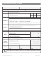
Performance Verification Procedure
Model / Serial Number:
Service Order / Inventory Number:
Hospital Name / Reference:
Inspection ch3
Software Version:
Physical inspection and clean
Lubricate pincher cavity as required
Updates
Recommended when serviced
UPDATE REF:
Fitted
Not fitted / Not
Applicable
Fit Strain Relief and Flexi Cable
CH6
Check all functions in self-test
Dry set pressure verification (self-test 12) Use a dry set.
Self Test ch4
Applied pressure = 0 mmHg
Displayed pressure = -20 to +10 mmHg
Applied pressure = 400 mmHg
Displayed pressure = 367 to 423 mmHg
Vacuum retention verification (self-test 27)
With door closed and set installed displayed pressure < -250 mmHg for 30 seconds
Alarms functionality check
Infusing
CH3
LOAD SET, DOOR, AIL, FLOW SENSOR, VTBI, KVO, TIME OUT, UPSTREAM OCCLUSION, BOTTLE CLAMP,
DOWNSTREAM PRESSURE EXCEEDED, SET OUT
Ensure pump works on battery and AC mains
Check operation with and without a Flow Sensor
ON HOLD/OFF CH3
APO test (10 psi with door open and closed)
Rate accuracy test
Verification
Tests CH3
Set pump infusing at 800 ml/h for 180 seconds ± 0 5 seconds
Delivery = 38 to 42 ml
_____________ ml
Downstream pressure exceeded test
Pressure set to 500 mmHg
Pump occludes between 11 and 14 psi
Setup
_____________ psi
Set rate to zero (or lowest value possible), Clear Volume Infused and VTBI
Clear Error / Alarm / Battery logs (as required)
Class I Type CF
Electrical
Safety TestS
Alternatively attach printed test results
Earth Resistance Test <= 0.2 Ω
_____________ Ω
Earth Leakage Current <= 500 µA
_____________ µA
Enclosure Leakage Current <= 100 µA
_____________ µA
Verification
Performed
By
CHX indicates
_______________________________
_____________________________
_______________________
Sign
Print
Date
the chapter number in the Technical Service Manual (TSM) E.G.
CH4 =
Refer to TSM Chapter 4.
NOTE: The content of this Performance Verification procedure is accurate at the time of issue of this TSM and is based on PVP
100 Issue 2.
IVAC® Volumetric Pump (Models 571 & 572)
36/104
1000SM00018 Issue 3
Chapter 4
Troubleshooting
In this chapter
Introduction
38
Error Messages
38
General Faults
42
Introduction
Use this troubleshooting guide to help identify the cause of errors and faults which may occur as a result of damage
to the pump or failure of an internal component. The following tables list the error messages and general faults and
describe what action to take to resolve the problem. For information on alarm procedures and messages, refer to the
relevant DFU.
If the nature of the problem is unclear, enter self-test mode and step through the self-test functions
to check that the main functions of the pump are operating correctly. See Chapter 3, 'Routine
Maintenance' for details.
Test 016 READ ALARM HISTORY displays the sixteen most recent malfunction messages. To run test
016, enter self-test mode and select the test. See Chapter 3 for instructions.
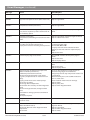
Error Messages
Message
Failure
Action/Replace
AIR IN LINE
Air in IV infusion set detected by air-in-line
sensor.
IV infusion set removed from air-in-line detector
or is not installed in lower tubing guides.
Purge air from IV infusion set. Check air-in-line
sensor is clean.
Check IV infusion set is properly installed in the airin-line detector and into lower tubing guides.
AIR IN LINE
non-flow sensor
operation
Air in IV infusion set detected by air-in-line
sensor.
Empty container; clamp closed, upstream
occlusion, flow sensor mispositioned, tubing/
bottle venting incorrect.
Purge air from IV infusion set.
Check VTBI is set.
Check equipment set up.
persistent
AIR IN LINE
Air-in-line transmitter or receiver failure.
VCO or timer failure.
Replace air-in-line receiver on the front panel.
Replace air-in-line transmitter on the door.
Replace Accessory Interface Board.
BOTTLE CLAMP
flow sensor
operation only
No fluid flow.
Empty container; clamp closed, upstream
occlusion, flow sensor mispositioned, tubing/
bottle venting incorrect.
Check equipment set up
CHECK DISC
non-flow sensor
operation only
Foreign matter lodged between pressure
transducer and pressure disc.
Pressure sensing disc improperly seated in
retainer.
Remove pressure disc, inspect and remove any
foreign matter then re-install disc.
Open and close door to reestablish vacuum.
If problem persists, check for blocked vacuum
ports or leaks. See FIX ME Q actions.
Upgrade software to Rev 3.01.
COM LINE
Communication with external device has been
only when pump
disconnected.
connected to a CIM
Check connections; Check that external device is
functioning.
Important: Test 024 CIM ID must be set to OFF
when CIM is not in use.
DOOR
Door open.
Close and latch the door.
DOWNSTREAM
PRESSURE
EXCEEDED
Downstream restriction, kinked tubing, clogged
filter, or pressure limit exceeded.
Check overall setup, eliminate cause of alarm and
restart pump. Verify that maximum or default
pressure settings are not set too low for intended
clinical application.
EXT ALARM
Communication error between pump and
only when pump
external device.
connected to a CIM
IVAC® Volumetric Pump (Models 571 & 572)
38/104
Check connections; Check that external device is
operating correctly.
Important: Test 024 CIM ID must be set to OFF
when CIM is not in use.
1000SM00018 Issue 3
Error Messages (continued)
Message
Failure
Action/Replace
FIX ME 0
Microprocessor execution error.
Replace Logic Board.
FIX ME 1
Logic Board component failure (CRC check error). Replace Logic Board.
FIX ME 2
Microprocessor failure (CPU error).
Replace Logic Board.
FIX ME 3
RAM contents lost following loss of power. (RAM
error). Occurs at power up after reconnection of
AC and battery power.
Recycle power ON/OFF switch; Replace Logic
Board.
FIX ME 4
Watchdog reset failure.
Microprocessor, Watchdog or Interconnect cable
failure.
Replace Logic Board and Power Regulator Board;
Replace interconnect cable.
FIX ME 5
Numeric Display segment failure.
Flex cable not correctly installed at J3.
Display driver circuit or checking circuitry failure.
Reseat flex cable into J3 ensuring cable tabs are in
line with connector tabs.
Run Tests 03, 04 and 05.
If Display and Front Panel switches function
properly and do not stick then replace Display
Board.
Replace flex cable.
FIX ME 6
Numeric Display digit select failure.
Run tests 03 and 17 to identify faulty digit or
switch.
Replace flex cable.
Replace Display Board.
FIX ME 7
Segment check circuit failure.
Remove power to Logic Board to power down
RAM.
Replace flex cable.
Replace Display Board.
FIX ME 8
Mechanism flag not detected at proper time
(Motor revolution period error).
Insufficiently lubricated mechanism.
Failed or misaligned rotation sensor optics.
Flag loose, mispositioned on mechanism cam
pulley.
Slipping mechanism cam or motor pulleys.
Failed cable assembly.
Failed Logic Board components.
Failed motor drive circuitry on Power Regulator
Board.
Failed or misaligned motor; misaligned front
panel.
Cam followers damage; jammed cam follower
assembly.
Failed pressure plate.
Clean any dried solution in mechanism then
lubricate along edges of cam followers.
Verify pulleys do not slip; verify motor rotates and
is not binding.
Rotate motor by hand, run test 22 and observe
port 16, bits 0 and 1.
Check red/black motor wires for damage.
Replace motor.
Replace pulley belt.
Replace Power Regulator Board.
FIX ME 9
Microprocessor malfunction (Background
execution error).
Follow FIX ME 1 actions.
FIX ME A
Motor current not detected during power-up
(Motor shutdown failure).
Failed Logic Board or Power Regulator Board
components.
Failed motor.
Replace interconnect cable (Logic Board to power
Regulator Board).
Replace Logic Board.
Replace Power Regulator Board.
Replace motor.
IVAC® Volumetric Pump (Models 571 & 572)
39/104
1000SM00018 Issue 3
Error Messages (continued)
Message
Failure
Action/Replace
FIX ME B
U14 on Logic Board failed power-up test
(Counter timer failure).
Replace Logic Board.
FIX ME C
Watchdog circuit failure at power-up.
Replace Power Regulator Board.
Replace Logic Board.
FIX ME D
Speaker checker failure at power-up.
Replace speaker; Replace Power Regulator Board.
FIX ME E
Speaker failure at power-up.
Speaker disconnected or failed.
Replace speaker; Replace Power Regulator Board.
FIX ME F
A/D converter failure at last power-down.
Replace Logic Board or Analog Board.
Check power supply reference voltage: On Power
Regulator Board, test point = positive side of C16,
limits 5.12 ±0.01 VDC; if not adjust R36.
FIX ME G
Watchdog check failure at last power-down.
Replace Power Regulator Board.
FIX ME H
Incorrect pressure applied during pressure
calibration or internal adjustments out of
tolerance.
Ensure correct calibration pressures are used, see
'Dry Set Pressure Calibration' procedure.
Verify that pressure unit selection switch is in the
correct position.
Replace vacuum/pressure transducer assembly.
FIX ME J
Pressure transducer failure.
Check pressure adjustments, see FIX ME H.
Replace pressure transducer/vacuum assembly.
FIX ME K
CIM ID entered without a CIM connected.
Change CIM ID setting to OFF, see test 024.
FIX ME L
EEPROM failure
Replace Logic Board.
FIX ME M
Air-in-line failure.
Replace air-in-line receiver on the front panel.
Replace air-in-line transmitter on the door.
Replace Accessory Interface Board.
FIX ME N
Motor rotation direction is reversed.
One or both motor rotation sensors failed.
Check that connectors J13 and J16 on Accessory
Interface Board are not reversed.
Replace rotation sensor assembly.
FIX ME P
Set sensor failure:
Set sensor detection failed when tested.
Sensor exposed to direct sunlight on latch side
of pump.
Locate pump away from direct sunlight.
Replace the set sensor assembly.
FIX ME Q
Vacuum system failure.
Install new IV infusion set and run test 27. Verify
that the vacuum reading is -250 or more negative
when door is closed.
Clean face of pressure transducer and check for
damage.
Check and replace Y-clip, door latch pin and door
latch as necessary.
Replace pressure transducer/vacuum assembly.
IVAC® Volumetric Pump (Models 571 & 572)
40/104
1000SM00018 Issue 3
Error Messages (continued)
Message
Failure
Action/Replace
FIX ME R
Vacuum detect circuit failure.
Replace Accessory Interface Board.
FIX ME S
Pump was operating in Secondary or CRIS mode
yet configured as PRI ONLY in test 031. (Infusion
mode error).
Replace Logic Board.
FLOW SENSOR
Drops splashing in drip chamber. Drip chamber
too full.
Improper secondary set.
Flow sensor mispositioned or removed/installed
while pump is running.
Check for proper flow sensor set up and eliminate
problem. For ambulation, slightly lower drip
chamber fluid level if necessary.
persistent
FLOW SENSOR
Flow sensor lenses obscured.
Flow sensor wiring open or short-circuited.
Analog Board circuitry failure.
Check for damage to flow sensor wiring from
receptacle to Logic Board.
Replace Analog Board, then Logic Board.
LOW BATT
alternating with
the selected
volume or pressure
status
Battery is almost discharged. Approximately 30
minutes of run time remain. Pumps continues to
run but sounds a low-pitched, audible tone to
alert user.
Operate on AC power. The battery will recharge
while operating on AC power.
LOW BATT
Battery discharged; insufficient charge to
operate pump.
The pump will sound an alarm and stop
operating.
Operate on AC power. The battery will recharge
while operating on AC power.
Note: A fully discharged battery can be recharged
to a full charge in approx. 24 hours with the pump
turned off and connected to AC power.
persistent
LOW BATT
(even after
charging)
Weak battery.
Battery charge circuit out of adjustment or
malfunctioning.
A/D converter (U16 on Logic Board) or Power
Regulator Board component failure.
Check battery voltage is 14.4 ± 0.05 VDC.
If necessary, adjust R10 on Power Regulator Board
to achieve 14.4 ± 0.05 VDC.
RECONFIG
REQUIRED
Invalid configuration or calibration data.
Run test 02 and identify invalid configuration then
set configuration as necessary.
If problem persists, run full self-test and perform all
calibration procedures.
SET OUT
IV infusion set removed or improperly loaded.
Incorrect IV infusion set used.
Load IV infusion set properly using correct IV
infusion set.
persistent
SET OUT
Set sensor does not detect that IV infusion set is
loaded.
Door sensor does not detect door is closed.
Magnet broken, missing from door latch or
magnet polarity reversed.
Check set sensor and door sensor using test 22.
Check for damaged or missing door latch magnet.
Check magnet polarity is correct.
TIME OUT
2 minutes have elapsed since pump put on hold
or since last switch was pressed.
A switch is stuck or has been pressed and held
for more than 1 minute.
Press the RUN/HOLD switch twice to continue
infusion.
UPSTREAM
OCCLUSION
non-flow sensor
operation
Clamp partially closed. Tubing above pump
kinked.
Fluid container is empty.
Check clamp is fully opened; Check for kinked
tubing.
Replace container if empty.
IVAC® Volumetric Pump (Models 571 & 572)
41/104
1000SM00018 Issue 3
General Faults
Fault
Failure
Action/Replace
Circuit breaker
tripped
Line voltage fluctuation.
Short circuit in power supply or wiring.
Fluid ingress.
Power Regulator Board component failure.
Reset circuit breaker once. If it trips again,
disconnect from AC power then:
Check mains inlet for fluid ingress.
Check power lead for damage.
Replace Power Regulator Board.
Replace transformer.
No response
Failed switch.
when switches are Failed or mispositioned flex cable.
pressed
Failed Display Board components.
Run test 17.
Test switches while opening and closing door.
Replace or reposition flex cable routed to J3.
Replace Bezel/Switch Panel assembly.
Replace Display Board.
No Display and no Fuse blown.
audible tone
ON/OFF switch failure.
Power Regulator Board or Logic Board circuitry
failure.
Bad battery.
Replace fuse F1 on Power Regulator Board.
Replace Bezel/Switch Panel assembly.
Check battery voltage is 14.4 ± 0.05 VDC, adjust
R10 on Power Regulator Board if necessary.
Replace Power Regulator Board or Logic Board.
No battery power
Clad fuse blown.
Battery is disconnected, has a wiring problem or
has failed.
Replace clad fuse on Power Regulator Board. If fuse
blows repeatedly, verify that the battery charge
voltage is 14.4 ± 0.05 VDC, adjust R10 on Power
Regulator Board if necessary.
Replace battery.
Scrambled or
frozen Display
Microprocessor malfunction.
Faulty flex cable.
Replace Logic Board.
Check flex cable connection at J3 of Display Board.
Replace Logic Board.
Momentary
Display
Pump has automatically shut off due to low
battery charge.
Plug power cord into AC mains.
Knocking noise
Dirt build-up around pressure plate.
Clean and inspect pressure plate.
Fuse blown (F1),
intermittent FIX
ME 0, FIX ME 3 or
halted alarms
3/8" test connector cover screw shorted out.
Replace 3/8" screw with 1/4" screw (300330).
IVAC® Volumetric Pump (Models 571 & 572)
42/104
1000SM00018 Issue 3
Chapter 5
Circuit Descriptions
In this chapter
Functional Module Block Diagram
44
Module Overview Functional Description
45
Functional Module Block Diagram
IVAC® Volumetric Pump (Models 571 and 572)
CHASSIS ASSEMBLY
Alarm
J6
Power Up
Circuit
A/D
Converter
Analog PCB
Drop
Discriminator
J8
Watchdog
J2
Speaker
External Test Connector
Battery
Motor
Control
P9
E1- / E2+
J1
Power
Regulator
Flow Sensor
(optional)
J5
Transformer
J4
Circuit Breaker
Logic PCB
RAM
J9
Power PCB
Main Processor
Mains Inlet
Line Filter
Pressure
Amplifier
J7
BODY ASSEMBLY
P7
Mechanism
Door Sensor
J16
J15
Pressure
Transducer
J14
J10
Vacuum Unit
J13
J11
Accessory Interface PCB
Rotation Sensor RO1
Rotation Sensor RO2
Motor
Vacuum
Detect
Ultrasonic
Air-In-Line
Pressure Transducer/
Vacuum Assembly
J1
J12
Air-In-Line
Receiver
DOOR ASSEMBLY
J3
J4
Air-In-Line
Transmitter
J1
Set Sensor
Display
Drivers
Display
Segments/Leds
J2
Bezel/Switch Panel
Display PCB
IVAC® Volumetric Pump (Models 571 & 572)
44/104
1000SM00018 Issue 3
Module Overview Functional Description
The IVAC® Volumetric Pump, Models 571 and 572 are designed to be serviced generally to major assembly level.
The main circuitry within the pump is contained on five printed circuit boards (PCBs): Logic PCB, Power Regulator PCB,
Display PCB, Accessory Interface PCB, Analog PCB and a switch panel.
CareFusion will make available, on request, circuit diagrams which will assist appropriately qualified technical personnel
to repair those parts of the device which are designated by the manufacturer as repairable.
Logic PCB
Power Regulator PCB
Contains the main processor module, memory circuits, I/O
circuits and associated support circuitry which provide
the control functions for almost all the aspects of the
pump. It drives and monitors all other modules using the
program code stored in the EPROM and the RAM ICs.
The Power Regulator PCB provides system power supplies,
AC line and battery charging functions, motor control,
watchdog and alarm driver circuits.
Main Processor
Consists of an 8-bit microcontroller with an internal
clock generator, vectored interrupts and 64k byte
addressing capability. The processor gets instructions
from the program memory (EPROM U1 and RAM U28,
U29) and then executes them.
Power Control Circuit (& On/Off Switch)
Consists of flip flop (U18) and gate (U17) which are
powered from the VRAM supply so are operational
even when the pump is off. The ON/OFF switch
enables power to the system. It uses a single push
switch on the front panel to toggle the flip flop (U18).
Note if the battery voltage falls below 10.2V, the
microprocessor asserts the OFF signal to toggle U18
into the power-off condition as if the ON/OFF switch
has been pressed.
Wait-State Generator
Memory Address Decoder
Decoding used to select EPROM U13 and RAMs U28
and U29 is provided by various logic circuits.
Read Only Memory (ROM)
The software program is stored in ROM (U13).
Electrically Erasable Programmable Read Only
Memory (EEPROM)
U27, a 128 byte EEPROM is used to retain important
user information such as calibration constants and
operating parameter configurations.
Random Access Memory (RAM) and RAM test
U28 is the read/write memory type and a second RAM,
U29, and various ICs form a hardware RAM test circuit.
I/O Decoding
A/D Converter
Analog Input Signals
Output Ports/Input Ports
Programmable Interval Timer
Data Bus Buffer
Transformer, Rectifier and Filter
Line Regulator
Performs two functions, it is the main power source
when the pump is connected to AC power and it keeps
the battery charged by providing a nominal charge
voltage of 2.35V per cell. The circuit uses an integrated
circuit (U1) , configured as a fixed-frequency pulse
modulation regulator.
AC Line Indicator
AC Power Signal
Power Control Circuitry
+5L Regulator
5.12V Reference and VRAM Regulator
5V Switching Regulator
Clock/Dividing Chain
Crystal Y1, with associated components form a crystal
oscillator which clocks a binary counter. This counter
provides a signal which in turn drives certain circuitry
such as the watchdog alarm and provides timing for the
line regulator and motor control circuitry.
Watchdog
Watchdog pulses enable this circuit to perform an
integrity check on the microprocessor, generating an
alarm if pulses are not received within a defined timing
window.
Alarm Circuitry
Motor Control Circuitry
The microprocessor drives the motor by stepping the
current through each motor winding in the correct order
to cause the motor shaft to turn. Digital signals from
the Logic PCB determine the direction and duration of
the current and the winding is increased/decreased to
ensure sufficient torque to move the mechanism and
to hold its position. The motor control circuit controls
current across a bridge to the windings of the stepper
motor using a pulse width modulation technique.
Battery
The sealed lead acid battery pack consists of six cells each
with a potential of 1.8V to 2.40V, connected in series, a clad
fuse (F2), and a 1.5A fuse (F1). The battery pack is rated at
2.5 Ah at 12 VDC.
IVAC® Volumetric Pump (Models 571 & 572)
45/104
1000SM00018 Issue 3
Module Overview Functional Description (continued)
Analog PCB
Transducer/Vacuum Assembly
Consists of two separate circuits, the drop discriminator
which monitors the flow status and the pressure amplifier
which amplifies the output of the pressure transducer.
The pressure transducer and the vacuum unit make up
this assembly.
Pressure measurement is detected by the pressure
sensor. Pressure sensor readings are provided by the
transducer output voltage taken from a bridge circuit
on the pressure transducer diaphragm.
A cylinder within the pump provides a vacuum to
ports surrounding the front face of the pressure
transducer to ensure firm coupling between the
pressure sensor disc pad of the IV infusion set and the
diaphragm of the transducer.
Drop Discriminator
The drop discriminator circuitry is only active when
a flow sensor is in use. The circuitry consists of a
synchronous demodulator, differential amplifier, an LED
driver, an AGC (automatic gain control) circuit and drop
simulator circuitry.
Pressure Amplifier
The pressure amplifier circuitry comprises four
functional blocks: the chopper/modulator input, the
instrumentation amplifier, the demodulator and the
output amplifier.
Accessory Interface PCB
Comprises the ultrasonic air-in-line detector and the
vacuum detection circuitry. It also acts as an interface
between the Logic PCB and various sensors and
periphery devices including the door sensor, pressure
sensor, Display PCB, motor and the rotation sensors.
Display PCB
This board comprises four 7-segment numeric displays,
two 4-digit alphanumeric modules, battery and AC
power LEDs and display circuitry which includes address
decoders, display drivers, and check circuitry. The bezel/
switch panel is an extension of the Display Board via P2.
Mechanism
The motor drives the timing pulley which in turn drives
the CAM, turning the rotation flag. The rotation flag
passes through the two rotation sensors. The function of
these two rotation sensors is to verify that the motor is
turning the correct direction.
Mains Inlet, Circuit Breaker and
Transformer
The AC line voltage is connected to the step-down
transformer through the circuit breaker. The secondary
output of the transformer provides a nominal 24 VAC
which is rectified through a full-wave rectifier, rectified
and converted into an unregulated DC voltage.
Air-In-Line Detector System
Comprises two parts: the air-in-line receiver on the front
panel and the air-in-line transmitter on the door. These
parts sandwich the IV infusion set tubing when the door
is closed and together with the air-in-line drive and
detect circuit they ultrasonically sense air in the fluid
path.
IVAC® Volumetric Pump (Models 571 & 572)
46/104
1000SM00018 Issue 3
Chapter 6
Spare Parts Replacement
Procedures
In this chapter
Introduction
48
Separating the Chassis and the Body
48
Chassis Assembly
49
Body Assembly
56
Door Assembly
68
Labels
76
Pole Clamp Assembly
81
Introduction
the pump is disconnected from the AC power supply and switched off before attempting to
service the pump
The pump contains static-sensitive components. Observe strict ESD precautions at all times
Batteries should be disposed of as outlined by the local country regulations: do not send back to
the manufacturer
Only use CareFusion recommended spare parts
Following all spare part replacement and repair activities, testing must be performed in accordance
with the Performance Verification Procedure (PVP), see Chapter 3, 'Routine Maintenance'
Ensure
Separating the Chassis and the Body
Replacement Procedure
1. Remove the two screws and washers securing the battery access cover then remove the battery access cover and
shield.
2. Slide out the battery pack and unplug the battery connector.
3. Remove the two screws from the bottom of the pump case.
4. Remove the two screws and two washers from the back panel of the chassis assembly.
5. Unplug the interconnect cable from the Accessory Interface Board.
6. Grasp and gently lift the battery housing then slide the chassis assembly out of the case.
7. Remove the one screw securing the earth wire to the mechanism assembly.
8. Reassemble in reverse order.
Refitting note:
Tuck the battery connector harness
(with large ferrite bead attached) into
the space at the top left of the battery.
Body Assembly
Chassis Assembly
Earth Wire
(I / J) Screw (x2) / Washer (x2) /
Adhesive thread
(H) Battery Connector Harness
(G) Battery Access Cover
(E) Screw (x2)
(F) Washer (x2)
(K) Screw (x2) /
Thread Adhesive
(A) Battery
(D) Screw
(C) Test Connector Cover
IVAC® Volumetric Pump (Models 571 & 572)
(B) Shield
48/104
(L) Interconnect Cable
If intermittent FIX ME 0, FIX ME 3 errors
are experienced, a blown fuse (F1),
halted alarms or the test connector
cover screw (item (D) is a 3/8" screw,
replace with 1/4" screw (300330).
1000SM00018 Issue 3
Separating the Chassis and the Body
Spare Parts
Item
Description
Part Number
A
B
C
D
E
F
G
H
H
I
J
K
L
L
BATT PACK,26X/56X/57X
SHIELD,BATT COVER,571/572
COVER,CONN ACCESS,56X/57X
SCREW,MACH 6-32X1/4 PNH PHH
SCREW,MACH 6-32X3/8 PNH PHH
WSHR,FL,.4BA T2 ST/STA2
COVER,ACCESS,BATT,571/572
ASSY, HARN, BATT, RFI, 56X/57X BOM
ASSY,HARN,BATT,56X/570(BOM)
SCREW,MACH 8-32X3/8 PNH PHH
WSHR,FL,.174X.380X.032,PS
SCREW,MACH 8-32X5/8 PNH PHH
HARN,INTC,FOLDED,571/572
HARN,INTCN,570
132412
136730 (Model XCX)
137715
300330
300034
0000ME00310
137503
136331 (Models XBX, XCX)
125429 (Model XAX)
300369
300038
300371
139435 (Models XBX, XCX)
132626 (Model XAX)
Chassis Assembly
Introduction
To replace the components within the chassis assembly, follow the instructions in the relevant sections of this chapter.
These sections are:
l
Separating the Chassis and the Body
l
Logic Board, Analog Board
l
Power Regulator Board
l
Transformer
l
Circuit Breaker, AC Line Filter
l
PE Connector
l
Battery Housing, Speaker, Rear Panel
IVAC® Volumetric Pump (Models 571 & 572)
49/104
1000SM00018 Issue 3
Chassis Assembly (continued)
Logic Board, Analog Board
Power Regulator Board
Replacement Procedure
Replacement Procedure
1. Remove the three screws (A) & (D) which secure the Logic
and Analog boards to the chassis.
1. Remove the three screws (I) and (A).
2. Remove the boards and slide out the flow sensor
receptacle retainer.
3. Unplug the flow sensor receptacle assembly from the Logic
Board (J5) and disconnect the interconnect cable (J6).
4. Remove the two screws which secure the boards together,
only unscrewing the third screw and hex standoff (B) from
the Analog Board if required.
2. Disconnect harness connections as required:
Transformer harness (J1)
Speaker harness (J2)
Interconnect cable (J4)
Battery harness cable
3. Reassemble in reverse order.
5. Separate the boards by unplugging the connector in
between the boards (J9) to (J9).
6. Reassemble in reverse order.
Spare Parts
Item
Description
Part Number
A
B
C
D
E
F
*
*
*
*
G
H
H
I
J
K
K.1
K.1
*
*
*
SCREW,MACH 6-32X1/2 PNH PHH
STDOFF,HEX 6-32X7/16 AL ALY
SCREW,MACH 6-32X3/8 PNH PHH
SCREW,6-20X7/8 PHN PHH
ASSY,ANLG BD,CAL,571/2(BOM)
SERV ASSY,LGC BD,571/2(BOM)
SERV ASSY,MEM,REV3.01,570(BOM)
KIT,UPGRD,REV 3.01,570 HARN,INTC,FOLDED,571/572
HARN,INTCN,570 RETAINER,REC
ASSY,FLOW SNSR BD,571/572
ASSY,HARN,DP SNSR REC,56X/57X
SCREW,TPG 6-20X3/8 BI PHH
ASSY,CABLE,FLAT,56X/57X(BOM)
ASSY,PWR REG BD,CAL,56X/57X
ASSY, HARN, BATT, RFI, 56X/57X BOM
ASSY,HARN,BATT,56X/570(BOM)
CLIP,FUSE PC/TABS 0.250 DIA
FUSE,SUB-MINI 5A 125V
FUSE,1.5A,250V,NORM-BLO
301828
302561
300034
303447
139866
139865
145071 (Logic Bd U13)
145070 (Logic Bd U13)
139435 (Models XBX, XCX)
132626 (Model XAX)
125382
137032 (Models XBX, XCX)
125436 (Model XAX)
301407
10014086
139867
136331 (Models XBX, XCX)
125429 (Model XAX)
303164
303425
303910
* item not shown
IVAC® Volumetric Pump (Models 571 & 572)
50/104
1000SM00018 Issue 3
IVAC® Volumetric Pump (Models 571 & 572)
51/104
1000SM00018 Issue 3
(J ) Interconnect Cable
(Logic Bd to Power Bd)
(A) Screw (x2)
(B) Hex Standoff
(C) Screw (x3) / Loctite 243
(D) Screw (x1)
Speaker harness
Transformer
harness
(K.1) Battery harness cable
(I) Screw (x1)
(A) Screw (x2) / Loctite 243
(H) Flow Sensor Receptacle Assembly
(G) Flow Sensor Receptacle Retainer
(F) Logic Board
(K) Power Regulator Board
(E) Analog Board
Logic Board, Analog Board, Power Regulator Board (continued)
Chassis Assembly (continued)
Chassis Assembly (continued)
Transformer
Refitting note: When refitting the transformer,
circuit breaker and AC line filter, it is important
to ensure that the transformer wires are placed
under the Power Regulator Board retainer (D)
without being pinched:
1. Position the retainer.
2. Place wires under tab guide of retainer.
3. Secure transformer with the four screws.
Replacement Procedure
1. Remove the four screws and washers securing the
transformer assembly. Remove the transformer
assembly.
2. Remove the Power Regulator Board retainer.
3. As required, cut away heat shrink then desolder and
remove the black and white wires from the circuit
breaker.
4. Disconnect the cable harness from the Power
Regulator Board (J1).
(D) Power Regulator Board Retainer
(C) Transformer
5. Reassemble in reverse order.
Transformer Cover
(B) Washer (x4)
(A) Screw (x4)
Transformer
Circuit Breaker
WHT
BLK
Heat shrink
Spare Parts
Item
Description
Part Number
A
B
C
D
SCREW,MACH 8-32X1 1/2 PNH PHH
WSHR,SPLIT,.168X.296X.040,PS
ASSY,XFMR,220V 571/572(BOM)
RETAINER,PW BD
301126
300037
139009
125383
IVAC® Volumetric Pump (Models 571 & 572)
52/104
1000SM00018 Issue 3
Chassis Assembly (continued)
Circuit Breaker, AC Line Filter
Replacement Procedure
1. Remove the knurled nut which secures the circuit breaker button to the rear panel.
2. Desolder and remove the black and white wires, cutting away heat shrink as required. Disconnect the crimp
connectors. Remove the circuit breaker.
3. Remove the two screws from the mains inlet on the outside of the rear panel and the two kep nuts securing the AC
line filter on the inside.
4. Disconnect the blue, brown and ground lug wires from the AC line filter.
5. Slide the AC line filter out from the back, removing the two adapters (one adapter on Models XBX, XCX).
6. Reassemble in reverse order.
Refitting notes:
When refitting the AC line filter:
(F) Washers (x2)
Place one of the adapters over on the AC line filter with the
thick section at the top. Slip the AC line filter through the
back then place the 2nd adapter over the filter with the
thick section at the bottom.
(B) Kep Nut (x2)
Ensure the AC line filter is orientated so that the earth pin is
nearest to the outer edge of the pump.
Models XBX, XCX
Knurled Nut / Circuit Breaker Button
(E) Screw (x2)
(D) AC Line Filter
(A) Circuit Breaker
(C) Adapter
Heat shrink
Transformer
(B) Kep Nut (x2)
(C) Adapter (2nd)
not on Models XBX, XCX
WHT
BLK
Ground Lug
Spare Parts
Item
Description
Part Number
A
B
C
D
E
F
BREAKER,CIRCUIT,571/572
NUT,KEP 6-32 S PL
ADPT,LINE FILTER,56X/57X/220V
FILTER,EMI,LINE,120/250,1A
SCREW,MACH 6-32X3/4 PNH PHH
WSHR,FL,M 6,BRASS,NICKEL PLT
137441
300036
125389
304746
300360
303736
IVAC® Volumetric Pump (Models 571 & 572)
53/104
1000SM00018 Issue 3
Chassis Assembly (continued)
PE Connector
Replacement Procedure
1. Remove the three hex nuts and washers from inside the rear panel.
2. Cut the tie strap securing the ground wires.
3. Remove the PE stud connector and washer from the rear panel.
4. Reassemble in reverse order.
Refitting note:
If not already fitted, secure the ground wires with a tie strap.
(F) Washer
(G) PE Connector
AC Line Filter
Circuit Breaker
(E) Ground Symbol Label
Ground wires
(A) Hex Nut (x2)
(B) Hex Nut
(C) Washer
(D) Washer (x2)
Spare Parts
Item
Description
Part Number
A
B
C
D
E
F
G
NUT,HEX 6MM METRIC,3.2MM THK
NUT,HEX METRIC, M6, 5MM THK
WSHR,FL,M 6,BRASS,NICKEL PLT
WASHER,EXT T LKG,6MM,CS CAD PL
LBL,GND SYM
WSHR,COLOR CODE,YEL/GRN,NPS
CONN,PLUG 0.984 MTG STUD
303742
303740
303736
303737
123273
303739
303734
IVAC® Volumetric Pump (Models 571 & 572)
54/104
1000SM00018 Issue 3
Chassis Assembly (continued)
Battery Housing, Speaker, Rear Panel
Replacement Procedure
1. Disconnect the speaker harness from the Power Regulator Board (J2).
2. Remove the speaker assembly by breaking it loose from the battery housing.
3. Remove the two nuts securing the battery housing to the rear panel assembly.
4. Remove the CE panel and rear panel as required.
5. Reassemble in reverse order.
Refitting note:
Use Loctite 38050 to fix the speaker in place.
(E) Rear Panel
(D) CE Panel
(B) Nut (x2)
Speaker harness
(C) Battery Housing
(A) Speaker Assembly / Loctite 38050
Models XBX, XCX
Spare Parts
A
B
C
D
E
ASSY,SPEAKER,56X/57X(BOM)
NUT,KEP 6-32 S PL
HSG,BATT,56X/57X
KIT,CE PANEL,571/2
ASSY, PANEL REAR ,RFI,571/572XB
IVAC® Volumetric Pump (Models 571 & 572)
125425
300036
125318
136853
137851
55/104
1000SM00018 Issue 3
Body Assembly
Introduction
To replace the components within the body assembly, follow the instructions in the relevant sections of this chapter.
These sections are:
l
Separating the Chassis and the Body
l
Y-Clip, Pressure Transducer/Vacuum Assembly
l
Door Sensor Assembly
l
Air-In-Line Receiver Assembly
l
Pincher Mechanism
l
Mechanism Assembly: Rotation Sensor Assembly, Motor, Timing Pulleys, Belt
l
Accessory Interface Board
l
Separating the Front Panel Assembly from the Case
l
Cover Assembly, Handle, Bumpers, Fastener Clips
Important note: The Front Panel and the Door are not serviceable.
If replacement of these components is required, contact your local CareFusion Affiliate Office or
Distributor for advice.
Y-Clip, Pressure Transducer/Vacuum Assembly
Replacement Procedure
1. Remove the one screw and two washers securing the Y-clip. Remove the Y-clip.
2. Remove the two mounting screws securing the pressure transducer to the front panel.
3. Remove the two screws securing the vacuum unit to the front panel.
4. Pull the tubing (which connects the pressure transducer and the vacuum unit) out of the retaining clip.
5. Disconnect the vacuum unit connector (J10) and the pressure transducer (J15) from the Accessory Interface Board,
removing cable ties as required.
6. Withdraw the pressure transducer/vacuum assembly from the body.
7. Remove the plunger spring from the vacuum unit as required.
8. Reassemble in reverse order.
Spare Parts
Item
Description
Part Number
A
B
C
D
E
F
G
H
CLIP,Y,570
WSHR,FL,.174X.380X.032,PS
SCREW,MACH,6-32X3/16,PNH,PHH
SCREW,MACH 8-32X1/4 PNH PHH
SERV ASSY,PRES,VACUUM,57X
SPRING,PLUNGER,56X/57X
SCREW MACH 6-32 X3/8 PNH PHHSS
CLIP,CORD,.18 DIA,ADH BK,NYL
132801
300038
304209
300055
141176
133246
303938
303106
IVAC® Volumetric Pump (Models 571 & 572)
56/104
1000SM00018 Issue 3
IVAC® Volumetric Pump (Models 571 & 572)
57/104
1000SM00018 Issue 3
(A) Y-Clip
(G) Screw (x2)
Front Panel
(F) Spring
(B) Washer (x2)
(C) Screw
To J10
Case Assembly
To J15
(D) Screw (x2)
Cable Tie
Transducer Assembly
(E) Vacuum Unit
Y-Clip, Pressure Transducer/Vacuum Assembly (continued)
Body Assembly
(H) Tubing Retainer Clip
Body Assembly (continued)
Door Sensor Assembly
Replacement Procedure
1. Unfasten the one retaining clip which secures the door sensor assembly to the inside of the front panel.
2. Disconnect the wiring harness (J11) from the Accessory Interface Board, removing cable ties as required.
3. Withdraw the door sensor assembly.
4. Reassemble in reverse order.
Refitting note:
Insert the door sensor assembly through the front panel, mount on peg and secure with clip.
To provide a clear view of the fitting area, the
illustration below shows the door removed. The door is
not serviceable.
If a replacement door is required, contact your local
CareFusion Affiliate Office or Distributor for advice.
Cable Tie
(A) Fastener Clip
(B) Door Sensor Assembly
Spare Parts
Item
Description
Part Number
A
B
FSTNR,SPD NUT LKG 0.250 SSTUD
ASSY,DOOR SNSR BD,56X/57X(BOM)
302902
132536
IVAC® Volumetric Pump (Models 571 & 572)
58/104
1000SM00018 Issue 3
Body Assembly (continued)
Air-In-Line Receiver Assembly
Replacement Procedure
1. Remove the two screws securing the air-in-line receiver assembly to the front panel.
2. Disconnect the wiring harness from the Accessory Interface Board (J1) and pull the wiring harness free of the silicone
fixing on the inside of the front panel.
3. Remove the air-in-line receiver assembly, drawing the wiring harness out through the front panel hole..
4. Reassemble in reverse order.
To provide a clear view of the fitting area, the
illustration below shows the door removed. The door is
not serviceable.
If a replacement door is required, contact your local
CareFusion Affiliate Office or Distributor for advice.
(B) Air-In-Line Receiver
Refitting note:
(A) Screw (x2)
Secure the wiring
harness with
adhesive silicone,
RTV 162 as shown
Front Panel Back View
Spare Parts
Item
Description
Part Number
A
B
SCREW,CAP,4-40X1/4,BUTH,HXSO
ASSY,AIL,RECEIVER,57X(BOM)
304172
133996
IVAC® Volumetric Pump (Models 571 & 572)
59/104
1000SM00018 Issue 3
Body Assembly (continued)
Pincher Mechanism
Replacement Procedure
1. Remove the one screw securing the pincher mechanism to the front panel.
2. Remove the cover plate, spring and the pincher.
3. Reassemble in reverse order.
Refitting note:
Use Loctite 243 on the securing screw.
To provide a clear view of the fitting area, the
illustration below shows the door removed. The door is
not serviceable.
If a replacement door is required, contact your local
CareFusion Affiliate Office or Distributor for advice.
(B) Pincher
(D) Spring
(C) Cover
(A) Screw / Loctite 243
Spare Parts
Item
Description
Part Number
A
B
C
D
SCREW,CAP 6-32X1/4 FLH HXSO
PINCHER,56X/57X
COVER,PINCHER,56X/57X(BOM)
SPRING,CAM,56X
301164
133248
125321
125768
IVAC® Volumetric Pump (Models 571 & 572)
60/104
1000SM00018 Issue 3
Body Assembly (continued)
Mechanism Assembly
To carry out repairs and/or replacement of the body assembly components, follow the instructions in the relevant
sections of this chapter.
Important: Breakdown of the mechanism assembly is limited to replacement of the motor, the rotation
sensor assembly, the two timing pulleys and the timing belt only. Do not attempt to disassemble the
Front Panel Assembly any further.
If repair of any other mechanism components is necessary, contact your local CareFusion Affiliate
Office or Distributor for advice.
Rotation Sensors
To J13
Timing Pulley (small)
To J16
Timing Pulley (large)
Mounting Plate
Belt
To J14
Motor
Rotation Sensor Assembly
Replacement Procedure
1. Disconnect the rotation sensor assembly wiring harness from
the Accessory Interface Board (J16 = back sensor, J13 = front
sensor), removing cable ties as required.
2. Remove the one screw which secures both rotation sensors.
Withdraw the rotation sensor assembly.
3. Reassemble in reverse order.
Refitting note:
After fixing the rotation sensors, rotate the motor timing pulley
and adjust the rotation sensor slot to ensure that the optical flag
rotates freely.
(B) Screw
(A) Rotation Sensors
Spare Parts
Item
Description
Part Number
A
B
ASSY,HARN,ROTN SNSR,56X/57X
SCREW,MACH 4-40X5/8 PNH PHH
125445
300347
IVAC® Volumetric Pump (Models 571 & 572)
61/104
1000SM00018 Issue 3
Body Assembly (continued)
Mechanism Assembly (continued)
Motor
Timing Pulleys, Belt
Replacement Procedure
Replacement Procedure
1. Disconnect the motor connector (J14) from the Accessory
Interface Board, removing cable ties as required.
1. Loosen the set screw securing the large pulley
timing assembly then pull up to remove it from
the cam shaft.
2. Holding the motor in place, use a flexible or right-angled
screwdriver to remove the two screws which secure the motor
to the motor mounting plate.
3. Remove the motor.
4. Measure and record the distance between the small timing
pulley and the motor surface.
2. Remove the belt from around the pulley as
required.
3. Reassemble in reverse order, referring to
'Refitting notes' on the next page.
5. Loosen the set screw which secures the small timing pulley to
the motor then pull up to remove it.
6. Reassemble in reverse order, referring to 'Refitting notes' on the
next page.
To provide a clear view of the fitting area, the mechanism is shown here broken
down, however, breakdown of the mechanism assembly is limited to replacement of
the motor, the rotation sensor assembly, the two timing pulleys and the timing belt.
Do not attempt to disassemble the Front Panel Assembly any further.
(B) Belt
(C) Timing Pulley (small)
(A) Timing Pulley (large)
Set Screw
Cam Shaft
(D) Motor
(E) Screw (x2)
Spare Parts
Item
Description
Part Number
A
B
C
D
E
ASSY,TIMING PULLEY,57X(BOM)
BELT,TMG 79GRV 0.080P
PULLEY, TMG 24 GRV 0.080P
MOTOR 4-WIRE 56X57X
SCREW,MACH 6-32X3/8 PNH PHH
131002
302878
302876
10013683
300034
IVAC® Volumetric Pump (Models 571 & 572)
62/104
1000SM00018 Issue 3
Body Assembly (continued)
Mechanism Assembly (continued)
Motor, Timing Pulleys, Belt (continued)
Refitting notes:
1) When refitting the motor, align the two diagonal motor mounting holes with the motor mounting plate before
securing the motor in place with the two screws. Use Loctite 243 on the two screws.
2) When refitting timing pulley (small) onto a replacement motor, install it at the same height as recorded from the old
motor.
3) When refitting the belt, verify the belt tension by pushing on the belt between the pulleys. The belt should easily push
(> 5 pounds of force) by approx. 0.1 to 0.2 inches. Tighten or loosen the belt as required:
Loosen the two motor screws and hold the motor to the mounting plates
Push motor towards the front of the case to lessen belt tension OR pull the motor towards the rear of the case to
increase belt tension.
Retighten the two screws and recheck belt tension.
4) Position timing pulley (large) onto the cam shaft just far enough to keep it off the mechanism plate then tighten the
set screw. When replacing the timing pulley (large), tighten the set screw onto the flat of the cam shaft to ensure
correct flag orientation.
Turn timing pulley (large) so the flag on the timing pulley passes through the optical sensors freely. Ensure the flag
does not rub the sensors. If so, loosen the rotation sensor fixing screw, reposition the flag then retighten the rotation
sensors screw ensuring the rotation sensors do not move.
IVAC® Volumetric Pump (Models 571 & 572)
63/104
1000SM00018 Issue 3
Body Assembly (continued)
Accessory Interface Board
Replacement Procedure
1. Unplug all cables connected to the Accessory Interface Board, including the flex cable (J12).
2. Using a right-angled Phillips screwdriver, remove the 3 screws and 1 washer securing the Accessory Interface Board to
the case.
3. Withdraw the Accessory Interface Board from the body, removing the strain relief pad from between the case
standoffs as necessary.
4. Reassemble in reverse order, referring to 'Refitting notes' on the next page.
To provide a clear view of the fitting
area, the illustration below shows a
front view of the case. Fitting is only
carried out from the rear of the case.
Standoff
(B.3) Strain Relief Pad
(B.2) Shield
J12 connector
(B.1) Flex Cable
(C) Washer
(A) Accessory Interface Board
(B.4) Screw (x3)
a strain relief pad (B.3) is not present, fit pad (145271) between the Accessory Interface Board
and the case by positioning it between the mounting standoffs on the case
Ensure that the shield (B.2) is the larger-size shield (141574) which covers all exposed leads in
the path of the flex cable as shown below. Check the part number and replace existing shield as
necessary
If
Spare Parts
Item
Description
Part Number
A
B
B.1
B.1
B.2
B.3
B.4
C
ASSY,ACC INTFC BD,CAL,57X(BOM)
KIT,STRAIN RELIEF/FLEX CBL,571/572
FLEX CBL,RFI,571/572
CBL,FLEX,56X/57X
SHIELD,ACC INTFC BD,57X
STRAIN RELIEF,CBL,57x
SCREW,MACH 6-32X1/4 PNH PHH
WSHR,INT TTH,.146X.283X.019,P
141590
145272
139753 (Models XBX, XCX)
140787 (Model XAX)
141574
145271
300330
300389
IVAC® Volumetric Pump (Models 571 & 572)
64/104
1000SM00018 Issue 3
Body Assembly (continued)
Accessory Interface Board (continued)
Refitting notes:
1) When refitting the flex cable, first carefully route the cable through the front panel and door grommets then connect
it to J12 connector.
It is important to firmly seat each pin into the connector using a birch stick (or equivalent tool or method), otherwise
intermittent contact may occur resulting in Display errors
2) When refitting the Accessory Interface Board take care not to loosen the flex cable connection at J12 or to move the
strain relief pad from its position between the standoffs.
+
U11
C17
R24
R25
J 2
J14
MOTOR
J10
VXDCR
R22
R32
R37
R31
U6
R19
R30
C23
1
1
1
R20
R23
R17
R29
R6
R35
Q2
VR2
R33
+
C22
C18
Apply the shield
to the area of the
board shown, on
the clad side.
R45
ASSY
51
R4
1
1
C3
C7
R9
R10
C19
C1
R11
R12
R13
C8
4 1
RN1
R27
CR2
CR3
CR1
U4
U5
J1
DOOR
+
C10
3
1
5
C12
AIL
J1
U2
C11
R21
J15
PRESS
R14
5
41
J16
J18
ROT
J13
R18
R40
R46
R42
R3
U1
C24
C13
6
U3
22
C16
R7
R26
R15
C14
C9
+
C2
R8
Shield Location
IVAC® Volumetric Pump (Models 571 & 572)
65/104
1000SM00018 Issue 3
Body Assembly (continued)
Separating the Front Panel Assembly from the Case
Replacement Procedure
1. Remove the two kep nuts securing the ground strap between the cover (inside top of case) and the front panel.
2. Unfasten the six retaining clips securing the front panel to the case. Separate the front panel assembly from the case.
3. Reassemble in reverse order.
Refitting note:
1) Use silicone (clear RTV coating, inner bond 140) around the case edge when refitting the front panel to the case.
To provide a clear view of the fitting area, the
illustration below shows the door removed. The door is
not serviceable.
If a replacement door is required, contact your local
CareFusion Affiliate Office or Distributor for advice.
(A) Fastener Clip (x6)
Ground Strap
(B) Kep Nut (x2)
Front Panel
Spare Parts
Item
Description
Part Number
A
B
FSTNR,SPD NUT LKG 0.250 SSTUD
NUT,KEP 6-32 S PL
302902
300036
IVAC® Volumetric Pump (Models 571 & 572)
66/104
1000SM00018 Issue 3
Body Assembly (continued)
Cover Assembly, Handle, Bumpers, Fastener Clips
Replacement Procedure
1. Using a right-angled Phillips screwdriver, remove the two screws securing the handle to the case. Remove the handle.
2. Remove the four screws which secure the bumpers to the bottom of the case. Remove the bumpers.
3. Reassemble in reverse order.
Refitting note:
To provide a clear view of the
fitting area, the illustration below
shows a front view of the case.
Fitting is only carried out from the
rear of the case.
When refitting the handle, use adhesive on the two
fixing screws.
(A.3) Handle
(A.2) Screw (x2)
Case Cover
(Part of cover assembly A, not
available separately)
(A.1) Mylar Shield
(A.4) Mylar Shield
(A.7) Bumper (x4)
(A.6) Screw (x4)
(A.5) Mylar Shield
Spare Parts
Item
Description
Part Number
A
A
A
A.1
A.2
A.3
A.4
A.5
A.6
A.7
KIT,COVER ASSY,CE,ENG,572
KIT,COVER ASSY,CE,ITAL,571
KIT,CVR ASSY,CE,SWED,571
SHIELD,PW BD
SCREW,MACH,8-32X3/8,PNH,PHH,S
ASSY,HANDLE/CAP,57X(BOM)
SHIELD,PW BD
SHIELD,MYLAR,XFMR CASE,57X
SCREW,MACH 6-32X1/4 PNH PHH
BUMPER,MLD 2093 W/ST WSHR INS
141555
141553
136740
125749
304330
134857
125412
129408
300330
301749
IVAC® Volumetric Pump (Models 571 & 572)
67/104
1000SM00018 Issue 3
Door Assembly
Introduction
To replace the components within the door assembly, follow the instructions in the relevant sections of this chapter.
These sections are:
l
Separating the Chassis and the Body
l
Bezel/Switch Panel, Display Board
l
Pressure Plate
l
Door Latch
l
Door Latch Pin
l
Air-In-Line Transmitter Assembly
l
Set Sensor, Pressure Disc Plunger
l
Pincher Cam Block
Important note: The Door and the Front Panel are not serviceable.
If replacement of these components is required, contact your local CareFusion Affiliate Office or
Distributor for advice.
Bezel/Switch Panel, Display Board
Replacement Procedure
1. Remove the four screws securing the bezel/switch panel and Display Board to the door assembly.
2. Ease the bezel/switch panel and Display Board assembly away from the door until it is possible to disconnect the
interconnect flex cable connector (H) from the back of the Display Board (J3).
3. Remove the four caps from the Bezel ground posts.
4. Remove the three screws securing the Display Board to the bezel/switch panel.
5. Carefully separate the Display Board and the bezel/switch panel then disconnect the flex cable connector (J2) from the
Display Board.
6. Disconnect the set sensor cable harness connector (J1) and the air-in-line harness connector (J4) from the Display
Board then remove the Display Board.
7. Remove the interconnect flex cable by sliding the cable out through grommets in the door and front panel.
8. Remove the mylar shield (E) from the Display Board as required.
9. Reassemble in reverse order.
IVAC® Volumetric Pump (Models 571 & 572)
68/104
1000SM00018 Issue 3
Door Assembly (continued)
Bezel/Switch Panel, Display Board (continued)
To provide a clear view of the fitting area, the door is shown below removed from its hinges.
Important: Do not remove the door from its hinges for servicing or replacement purposes.
If the door is damaged or a replacement is required, contact your local CareFusion Affiliate Office or
Distributor for advice.
(C) Hinge Pin
(D) Screw (x4) / Loctite 243
(F) Grommet, front panel
(B) Display Board
(A) Bezel/Switch Panel
(A.1) Foam
(G) Connector
(H) Interconnect flex cable.
See also 'Far Side View' below.
(I) Flex Cable
(K) Ground Cap (x4)
(J) Screw (x3)
Display Board
Door
(E) Mylar Shield
(F) Grommet
FOLD
Door
Door Grommet
IVAC® Volumetric Pump (Models 571 & 572)
Far Side View
69/104
1000SM00018 Issue 3
Door Assembly (continued)
Bezel/Switch Panel, Display Board (continued)
Refitting notes:
1) When refitting the Display Board, fold the interconnect cable as shown in the 'Far Side View' illustration (see previous
page).
2) Use Loctite 243 on the four screws (D) which secure the bezel/switch panel and Display Board to the door assembly.
3) Adhere the mylar shield on the solder side of the Display Board, centered on, and against the edge of the interconnect
cable connector, J3.
4) When refitting the interconnect flex cable carefully slide it through the front panel and door grommets. If necessary
lightly grease the cable with lub grease 33, on a cotton swab. It is important to ensure any grease is wiped away from
exposed cable using alcohol and lint-free cloth. If foreign matter remains, failure of the front panel/Display Board may
occur. See also 'Accessory Interface Board' for additional refitting notes.
Spare Parts
Item
Description
Part Number
A
ASSY,BEZEL/OVLY,ENG,571(BOM)
139002
A
ASSY,BEZEL/OVLY,ENG,572(BOM)
138999 (Models XBX, XCX)
A
ASSY,BEZEL/OVLY,FREN,571(BOM)
139000
A
ASSY,BEZEL/OVLY,DUT,571(BOM)
139001
A
KIT,BEZEL/OVLY,SPAN,571(BOM)
139003
A
KIT,BEZEL/OVLY,ITAL,571(BOM)
139004
A
ASSY,BEZEL/OVLY,SWED,571(BOM)
139005
A
KIT,BEZEL/OVLY,GER,571(BOM)
139006
A
SERV ASSY,BEZEL/OVLY,ENG,570
133207 (Model XAX)
A.1
FOAM,0.062TX0.125W GREY
302932
B
SERV ASSY,DSPL BD,57X(BOM)
139007
*
DSPL,7/SEG,ORANGE,COM CATH.400
302274 (DS3-6 on Display Board)
*
DIODE,LED,YEL,MV53154/HLMP3465
302762 (DS7,8 on Display Board)
*
DISPLAY,LED,RED,5X7 DOT MATRIX
303899 (DS1,2 on Display Board)
*
CONN,HDR,LTCH,4P,1X4,RA,AU
302797 (J1 on Display Board)
C
PIN,GRV 0.125X1.25 S ALLOY
302053
D
SCREW,CAP 4-40X5/8 HXSO
302466
E
SHIELD,MYLAR,56X/570
125413
F
GROMMET,FLEX STRIP
125359
G
CONN,FL FLEX RTANG 11P 0.100C
303612
H
FLEX CBL,RFI,571/572
139753 (Models XBX, XCX)
H
CBL,FLEX,56X/57X
140787 (Model XAX)
J
SCREW,MACH 4-40X1/4 PNH PHH
300345
K
CAP,GROUND,POST,571/572
137653
* item not shown
IVAC® Volumetric Pump (Models 571 & 572)
70/104
1000SM00018 Issue 3
Door Assembly (continued)
Pressure Plate
Replacement Procedure
1. Mark the face of the pressure plate to ensure it can be refitted with the correct top side upwards.
2. Remove the four screws and washers securing the pressure plate to the door.
3. Remove the pressure plate and two coil springs seated in the door recesses.
4. Reassemble in reverse order.
Important:
Each pressure plate is mated to the cam followers during manufacture burn-in. If the pressure
plate is damaged or a replacement is required, contact your local CareFusion Affiliate Office or
Distributor for advice.
Correct top-side-up orientation of the pressure plate must be observed when it is refitted.
Refitting notes:
1) Install the pressure plate with the correct top side upwards using the mark made on face when removed.
2) Use Loctite 243 on screws when refitting the pressure plate.
Pressure Plate
(B) Washer (x4)
(C) Screw (x4) / Loctite 243
(A) Spring (x2)
Spare Parts
Item
Description
Part Number
A
B
C
SPR,CPRSN,.360X.813X.813X.035,MW
WSHR,FL,.187X.438X.020,BLK,SS
SCREW,MACH 8-32X3/8 PNH PHH
302900
301594
301522
IVAC® Volumetric Pump (Models 571 & 572)
71/104
1000SM00018 Issue 3
Door Assembly (continued)
Door Latch
Replacement Procedure
1. Drive out the groove pin using a pin punch.
2. Remove the two curved spring washers and the door latch.
3. Remove the magnet cover and magnet as required.
4. Reassemble in reverse order.
Refitting notes:
1) When refitting the magnet, ensure the south pole faces outwards, secure magnet in place using loctite and cover.
2) Fit the two curved spring washers into the latch recesses outwardly, convex.
3) Fit the groove pin flush with the outside surface of the door.
(A) Groove pin
(D) Spring Washers (x2)
See
iew
eV
id
Ins
When refitting the
door latch, apply
lub grease 33 on
a cotton swab, to
entire length of slot
inside the latch.
(E) Latch
(B) Cover
(C) Magnet / Loctite 496
Inside View
Spare Parts
Item
Description
Part Number
A
B
C
D
E
E
PIN,GRV 0.125X1.25 S ALLOY
COVER,MAGNET
MAGNET,MAGNETIZED,CO 90C98A
SPRING,CVR,WSHR U-138-0045S
ASSY LATCH,GNRC,(BOM)
ASSY,LATCH,ENG,(BOM)
302053
125337
302425
301591
132777
132776 (with label)
IVAC® Volumetric Pump (Models 571 & 572)
72/104
1000SM00018 Issue 3
Door Assembly (continued)
Door Latch Pin
1. Pull out the old pin with pliers.
2. Reassemble in reverse order.
0.25 inches ± 0.15
(6.35 ± 3.81 mm)
Pin
Front Panel
Refitting the Door Latch Pin
(A) Pin
Air-In-Line Transmitter Assembly
Replacement Procedure
1. Disconnect the air-in-line cable harness connector (J4) from the Display Board.
2. Remove the two screws securing the air-in-line transmitter to the door.
3. Remove the air-in-line transmitter assembly by pulling it away from the door, drawing out the cable harness.
4. Reassemble in reverse order.
(B) Air-In-Line Transmitter
(C) Screw (x2)
Spare Parts
Item
Description
Part Number
A
B
C
P,GRV 0.125X.500 REV TPR
ASSY,AIL,TRANS,571/572(BOM)
SCREW,CAP,4-40X1/4,BUTH,HXSO
302269
137269
304172
IVAC® Volumetric Pump (Models 571 & 572)
73/104
1000SM00018 Issue 3
Door Assembly (continued)
Set Sensor, Pressure Disc Plunger
Replacement Procedure
1. Disconnect the set sensor assembly harness connector (J1) from the Display Board.
2. Grasp the body of the set sensor with pliers and turn anti-clockwise.
3. Break the set sensor assembly loose as it is glued in place.
4. Remove the one screw securing the pressure disc plunger.
5. Remove the pressure disc plunger and spring.
6. Reassemble in reverse order.
Refitting notes:
1) Thread the set sensor into the
door until the optical end is
recessed 0.25 inches + 0.05/0.15 from the recessed inner
circle on the inside face of the
door.
Door
2) Use Loctite 38050 and TAK
PAK 11525 accelerate to fix
the set sensor in place.
(C) Pressure Disc Plunger
(D) Screw
(B) Spring
(A) Set Sensor
Spare Parts
Item
Description
Part Number
A
B
C
D
ASSY,SET SNSR,571/572(BOM)
SPRING,PLUNGER,56X/57X
PLUNGER,PRESSURE,DISC,570XB
SCREW,MACH 6-32X3/8 TR PHH
139019
133246
133132
300701
IVAC® Volumetric Pump (Models 571 & 572)
74/104
1000SM00018 Issue 3
Door Assembly (continued)
Pincher Cam Block
Replacement Procedure
1. Break loose and remove the one screw and two washers securing the pincher cam block, they are glued in place.
2. Remove the pincher cam block.
3. Reassemble in reverse order.
(C) Pincher Cam Block
(B) Washer (x2)
(A) Screw
Refitting notes:
Fit and adjust the pincher cam block as follows:
1) Loosely secure the pincher cam block with the one screw and two washers.
2) Open the pump door and insert a 0.125" pin gauge in the clamp of the pincher mechanism on the front panel. The
pin must sit vertically and the pin tip must sit below the pressure plate. Locating it any higher will result in inaccurate
adjustment of the pincher cam block.
3) With the pincher cam block free to move but loosely held in place by the securing screw, close the pump door over
the pin gauge. Slide the securing screw to the right until the pincher cam block rests solidly against the pincher then
tighten the securing screw, taking care not to strip the plastic threads.
4) Apply Loctite 420 to the back of the door and around the pincher cam block. Allow to dry for a minimum of 10
minutes before removing the pin gauge.
5) Insert a 0.110" pin gauge in the clamp of the pincher mechanism on the front panel. The pin must sit vertically and the
pin tip must sit below the pressure plate.
6) Close the pump door. Verify that the pin drops out of the pincher mechanism. If not, readjust the pincher cam block.
Spare Parts
Item
Description
Part Number
A
B
C
SCREW,MACH 4-40X1/4 PNH PHH
WSHR,FL,.4BA T2 ST/STA2
PINCHER,CAM,56X/57X
300345
0000ME00310
125368
IVAC® Volumetric Pump (Models 571 & 572)
75/104
1000SM00018 Issue 3
Labels
(A)
(D)
(B)
(C)
4 21/32 ± 1/64 inches
(118.27 ± 0.397 mm
(F)
(E)
IVAC® Volumetric Pump (Models 571 & 572)
76/104
1000SM00018 Issue 3
Labels (continued)
(H)
(I)
(G)
(K)
(J)
(L)
(M)
(Q)
FLOW
SENSOR
(N)
(O)
PUSH
TO
RESET
(P)
(R)
Note: English text is printed on the rear panel
therefore labels (Q) and (R) are only required
for other languages.
IVAC® Volumetric Pump (Models 571 & 572)
77/104
1000SM00018 Issue 3
Labels (continued)
Spare Parts
Item
Description
Part Number
A
A
A
A
A
A
A
LBL,FLOW SNSR PLCMT,ENG,57X
LBL FLOW SNSR PLCMT GER 571
LBL,FLOW SNSR PLCMT,FREN,570/1
LBL,FLOW SNSR PLCMT,DUT,571
LBL FLOW SNSR PLCMT SWED 571
LBL FLOW SNSR PLCMT SPAN 571
LBL FLOW SNSR PLCMT ITAL 571
132152
135383
132712
137695
137693
137694
137692
B
B
B
B
B
B
LBL,PRES XDCR,ENG,57X(BOM)
LBL,PRES XDCR,GER
LBL,PRES XDCR,FREN
LBL,PRES XDCR,SWED
LBL,PRES XDCR,SPAN
LBL,PRES XDCR,ITAL
133215
125452.01
125452.02
125452.04
125452.05
125452.06
C
C
C
C
C
C
C
C
LBL,VPVP,ENG,572(BOM)
LBL VPVP ENG 571 (BOM)
LBL VPVP GER 571 (BOM)
LBL VPVP FREN 571 (BOM)
LBL,VPVP,DUT,571(BOM)
LBL VPVP SWED 571 (BOM)
LBL VPVP SPAN 571 (BOM)
LBL VPVP ITAL 571 (BOM)
135990
138658
135590
135589
137658
137651
137656
137649
D
D
D
D
D
D
D
D
LBL START UP ENG 571 (BOM)
LBL,START-UP,ENG,572(BOM)
LBL, START-UP, GER, 571 (BOM)
LBL, START-UP, FREN, 571 (BOM)
LBL,START-UP,DUT,571(BOM)
LBL START UP SWED 571(BOM)
LBL START UP SPAN 571(BOM)
LBL START UP ITAL 571(BOM)
138656
137463
137841
137839
137329
137646
137333
137642
E
LBL CE MARK INST MDD
136933
F
F
F
F
F
F
F
LBL,CAUT,ENG
LBL,CAUT,GER
LBL,CAUT,FREN
LBL,CAUT,DUT
LBL CAUT SWED
LBL CAUT SPAN
LBL CAUT ITAL
125392
125407.01
125407.02
125407.03
125407.04
125407.05
125407.06
G
G
G
G
G
G
G
G
G
ASSY,BEZEL/OVLY,ENG,572(BOM)
SERV ASSY,BEZEL/OVLY,ENG,570
ASSY,BEZEL/OVLY,ENG,571(BOM)
KIT,BEZEL/OVLY,GER,571(BOM)
ASSY,BEZEL/OVLY,FREN,571(BOM)
ASSY,BEZEL/OVLY,DUT,571(BOM)
ASSY,BEZEL/OVLY,SWED,571(BOM)
KIT,BEZEL/OVLY,SPAN,571(BOM)
KIT,BEZEL/OVLY,ITAL,571(BOM)
138999 (Models XBX, XCX)
133207 (Model XAX)
139002
139006
139000
139001
139005
139003
139004
IVAC® Volumetric Pump (Models 571 & 572)
78/104
1000SM00018 Issue 3
Labels (continued)
Spare Parts
Item
Description
Part Number
H
H
LBL,HANDLE,UPR,572
LBL HANDLE UPR 571
135992
135539
I
I
I
I
I
I
I
LBL,HANDLE,LWR,ENG,57X
LBL HANDLE LWR GER 571
LBL, HANDLE, LWR, FREN, 57X
LBL HANDLE LWR DUT 571(BOM)
LBL HANDLE LWR SWED 571(BOM)
LBL, HANDLE, LWR, SPAN, 571
LBL HANDLE LWR ITAL 571(BOM)
132394
135382
132713
137685
137683
137684
137682
J
J
J
J
J
J
J
LBL,PRESS TO OPEN,ENG
LBL,PRESS TO OPEN,GER
LBL,PRESS TO OPEN,FREN,56X/57X
LBL,PRESS TO OPEN,DUT
LBL PRESS OPEN SWED
LBL,PRESS TO OPEN,SPAN
LBL PRESS OPEN ITAL
125393
125451.01
125451.02
125451.03
125451.04
125451.05
125451.06
K
K
K
K
K
K
K
LBL,FLOW ARROW,ENG
LBL,FLOW ARROW,GER
LBL,FLOW ARROW,FREN,56X/57X
LBL,FLOW ARROW,DUT
LBL FLOW ARROW SWED
LBL FLOW ARROW SPAN
LBL FLOW ARROW ITAL
125497
125450.01
125450.02
125450.03
125450.04
125450.05
125450.06
L
L
L
L
L
L
L
LBL,TBG POSN,57X
LBL TBG POSN GER 571
LBL,TBG,POSN,FR/CAN,570
LBL TBG POS DUT 571(BOM)
LBL TBG POS SWED 571(BOM)
LBL TBG POS SPAN 571(BOM)
LBL TBG POS ITAL 571(BOM)
133208
135386
133430
137690
137688
137689
137687
M
LBL,S/N RPLCMNT
125569
N
N
N
N
N
N
LBL,NAME RATING,ENG,571/572
LBL,NAME RATING,FREN,571
LBL,NAME RATING,DUT,571
LBL NAME RATING SWED 571
LBL NAME RATING SPAN 571
LBL NAME RATING ITAL 571
137496
137960
137847
137648
137848
137644
O
LBL,PATENT NTC,571/572
137854
P
LBL,EQ POT CONN
133318
IVAC® Volumetric Pump (Models 571 & 572)
79/104
1000SM00018 Issue 3
Labels (continued)
Spare Parts
Item
Description
Part Number
Q
Q
Q
Q
Q
Q
LBL,FLOW SNSR,GER
LBL,FLOW SNSR,FREN
LBL,FLOW SNSR,DUT
LBL FLOW SNSR SWED
LBL FLOW SNSR SPAN
LBL FLOW SNSR ITAL
125406.01
125406.02
125406.03
125406.04
125406.05
125406.06
R
R
R
R
R
R
LBL PUSH TO RESET GER 571
LBL,PUSH TO RESET,FREN,571
LBL,PUSH TO RESET,DUT,571
LBL PUSH TO RESET SWED 571
LBL PUSH TO RESET SPAN 571
LBL PUSH TP RESET ITAL 571
137476
137475
137330
137645
137845
137641
*
LBL, WEEE Symbol
10012829
* item not shown
IVAC® Volumetric Pump (Models 571 & 572)
80/104
1000SM00018 Issue 3
Pole Clamp Assembly
Replacement Procedure
1. Referring to the 'Mounting steps' 1 and 2 on the next page, unlock the catch, levering it open with a blunt object such
as a coin if necessary.
2. Push the adapter bracket away from the backstop to release it then lift the pole clamp adapter up and off the screw to
remove it.
3. Using a hex key, loosen the one fixing screw at the bottom centre of the pump. Remove the screw.
4. Reassemble in reverse order.
Refitting notes:
1) Do not over-tighten the one fixing
screw when securing snugly with hex
key.
(A) Transport Adapter
2) See also 'Mounting steps' on the next
page.
(D) Screw
Catch
(B) Pole Adapter
(C) Clamp
(D) Screw
Catch
Note: Transport Adapter (B) is used in conjunction with Clamp (C)
Spare Parts
Item
Description
Part Number
A
B
C
D
TRANSPORT ADAPTOR WC
POLE ADAPTER
IV POLE CLAMP ACCESORY
POLE CLAMP HEX SCREW 56X/57X
5767C
5767A
BC100A
SCR-1347
IVAC® Volumetric Pump (Models 571 & 572)
81/104
1000SM00018 Issue 3
Pole Clamp Assembly (continued)
Mounting steps:
1) Push bracket forward to backstop.
Catch
Rivet
Lever Zone
2) Push catch in direction shown
to lock position.
Lock
Note: If necessary,
lever catch open
using blunt object
such as a coin.
LEVER
ZONE
Lock
Back Mount
Note: Use catch mouth furthest
position from rivet
Side Mount
Bottom Views
IVAC® Volumetric Pump (Models 571 & 572)
82/104
Important note: Use catch mouth nearest
position from rivet.
1000SM00018 Issue 3
Appendix A
Specifications
In this chapter
Infusion
84
Electrical
84
Physical
84
Environmental
84
Electromagnetic Compatibility
85
The following information is for reference purposes only. For more detailed specifications refer to relevant DFU.
Infusion
Rate range
1 to 999 ml/h
STANDARD RATE range
0.1 to 999.9 ml/h
ALL RATE range, with user selectable maximum rate
Volume infused range
0.1 to 9999.9 ml/h
KVO rate
5.0 ml/h or at current set rate whichever is less
Critical volume
Maximum incremental volume delivered in case of failure will not exceed 8.75 ml
System Accuracy
±5%
Infusion Set
IVAC "52" Series Volume Infusion sets
Occlusion pressure
Maximum: 500 mmHg (680 cmH20)
Mode of operation
Continuous
Electrical
Battery type
Lead acid, sealed, rechargeable. Automatically charges when the pump is connected to AC
power
Battery life
5 hours @ 125 ml/h with a fully charged, new battery
Battery recharge time
Approximately 24 hours from discharge to 100% charge
Power requirements
220 to 240V AC; 50/60 Hz; 0.25A; 3-wire grounded system
Memory retention
At 25°C, with a fully charged, new battery, the volatile memory configuration information will be
retained for at least 6 months
Ground current leakage
Maximum 100µA rms (ungrounded) at 220 Vrms to meet EN/IEC 60601-1
Protection against
electrical shock hazards
Class I
Physical
Weight
Approximately 6.5 kg
Case material
Blue enameled aluminium
Dimensions
W
H
D
12.7 cm
29.2 cm
19.3 cm
Environmental
IPX rating
IPX1
Temperature
Relative humidity
Atmostpheric pressure
Operating limits
+5°C to +40°C
20% to 90% non-condensing
700 - 1060 hPa
Transport/storage limits
-40°C to +60°C
10% to 100%
500 - 1060 hPa
IVAC® Volumetric Pump (Models 571 & 572)
84/104
1000SM00018 Issue 3
Electromagnetic Compatibility
Warning:
• The use of any accessory, transducer, or cable with the IVAC® Volumetric Pump other than those specified may result in
increased emissions or decreased immunity of the pump.
• The IVAC® Volumetric Pump should not be used adjacent to or stacked with other equipment, however if adjacent
or stacked use is necessary, the IVAC® Volumetric Pump should be observed to verify normal operation in the
configuration in which it will be used.
Caution:
• The IVAC® Volumetric Pump is a CISPR 11 Group 1 Class A Medical Equipment System and intended for use by
healthcare professionals only.
• Medical Electrical Equipment needs special precautions regarding EMC and needs to be installed, put into service and
used according to the EMC information provided in the accompanying documents.
• Portable and Mobile RF communications can affect Medical Electrical Equipment.
• Operating the pump near equipment which radiates high energy radio frequencies (electro surgical or cauterizing
equipment, portable radios, cellular telephones, etc.) may cause false alarm conditions. If this happens, reposition the
pump away from the source of interference or turn off the pump and manually regulate the flow.
Guidance and Manufacturer’s Declaration – Electromagnetic Emissions
The IVAC® Volumetric Pump is intended for use in the electromagnetic environment specified below.
The customer or the user of the IVAC® Volumetric Pump should assure that it is used in such an environment.
Emissions Test
Compliance
Electromagnetic Environment – Guidance
Group 1
The pump uses RF energy only for its internal function in the normal
product offering. Therefore, its RF emissions are very low and are not
likely to cause any interface in nearby electronic equipment.
CISPR 11
RF Emissions
CISPR 11
Class A
RF Emissions
EN 61000-3-2
Harmonic Emissions
EN 61000-3-3
Voltage Fluctuations,
Flicker Emissions
Class A
The pump is suitable for use in all establishments, other than
domestic, and those directly connected to the public low-voltage
power supply network that supplies buildings used for domestic
purposes.
Complies
Important: The IVAC® Volumetric Pump has been assessed to the following standards;
EN/IEC 60601-1-2:1993 (Models 571XAX, 572XAX & 572XBX)
EN/IEC60601-1-2:2001 (Models 571XBX & 572XCX).
IVAC® Volumetric Pump (Models 571 & 572)
85/104
1000SM00018 Issue 3
Electromagnetic Compatibility (continued)
Guidance and Manufacturer’s Declaration - Electromagnetic Immunity
The IVAC® Volumetric Pump is intended for use in the electromagnetic environment specified below.
The customer or the user of IVAC® Volumetric Pump should assure that it is used in such an environment.
Immunity Test
EN 61000-4-2 ElectroStatic Discharge (ESD)
EN 61000-4-4
Electrical Fast Transient,
Burst (EFT) (Note 3)
EN 61000-4-5
Power Line Surge
EN 60601-1-2
Test Level
±6 kV contact
±8 kV air
Compliance Level
Electromagnetic Environment – Guidance
±8 kV contact (Note
2)
Floors should be wood, concrete, or ceramic tile.
±15 kV air (Note 2)
If floors are covered with synthetic material, the
relative humidity should be at least 30 %.
±2 kV for power
supply lines
±2 kV for power
supply lines
Mains power quality should be that of a typical
commercial or hospital environment.
±1 kV for input/
output lines
N/A (Note 4)
±1 kV Line(s) to
Line(s)
±1 kV Line(s) to
Line(s)
Mains power quality should be that of a typical
commercial or hospital environment.
±2 kV Line(s) to
Earth
(Note 3)
±2 kV Line(s) to
Earth
EN 61000-4-8 Power
Frequency Magnetic Field
(50/60 Hz)
3 A/m
400 A/m 50 Hz
(Note 2)
Power frequency magnetic fields should be at
levels characteristic of a typical location in a
typical commercial or hospital environment.
EN 61000-4-11
<5 % UT (Note 1)
<5 % UT
Voltage Dips, Short
Interruptions, and Voltage
Variations
(>95 % dip in UT)
(>95 % dip in UT)
Mains power quality should be that of a typical
commercial or hospital environment.
for 0.5 cycle
for 0.5 cycle
40 % UT
40 % UT
(60 % dip in UT)
(60 % dip in UT)
for 5 cycles
for 5 cycles
70 % UT
70 % UT
(30 % dip in UT)
(30 % dip in UT)
for 25 cycles
for 25 cycles
<5 % UT
<5 % UT
(>95 % dip in UT)
(>95 % dip in UT)
for 5 sec
for 5 sec
(Note 3)
If the user of the pump requires continued
operation during power mains interruptions, it is
recommended that the pump be powered from
an uninterruptible power supply or a battery.
The pump does employ an internal short
duration battery.
Note 1—UT is the AC mains voltage prior to application of the test level.
Note 2—Compliance levels raised by EN 60601-2-24.
Note 3—Performed at the Minimum and Maximum Rated Input Voltage.
Note 4—CareFusion recommends using signal cables of less than 3 meters in length and this requirement is applicable only if signal cables are 3 meters
or more in length. (EN 60601-1-2:2002, Clause 36.202.4)
IVAC® Volumetric Pump (Models 571 & 572)
86/104
1000SM00018 Issue 3
Electromagnetic Compatibility (continued)
Guidance and Manufacturer’s Declaration—Electromagnetic Immunity
LIFE SUPPORT Equipment
The IVAC® Volumetric Pump is intended for use in the electromagnetic environment specified below.
The customer or the user of the IVAC® Volumetric Pump should ensure that it is used in such an environment.
Immunity Test
EN 60601-1-2
Test Level
Compliance
Level
Electromagnetic Environment – Guidance
Portable and mobile RF communications equipment should be used no
closer to any part of the pump, including cables, than the recommended
separation distance calculated from the equation applicable to the
frequency of the transmitter.
Recommended Separation Distance
EN 61000-4-6
3 V rms
10 V rms
Conducted RF
150 kHz to 80
MHz
(Note 3)
EN 61000-4-3
Radiated RF
3 V/m
80 MHz to 2.5
GHz
10 V/m
(Note 3)
3.5
d = [-----] √P
V1
12
d = [-----] √P 80 MHz to 800 MHz
V2
12
d = [-----] √P 80 MHz to 2.5 GHz
E1
23
d = [-----] √P 800 MHz to 2.5 GHz
E1
where P is the maximum output power rating of the transmitter in watts
(W) according to the transmitter manufacturer and d is the recommended
separation distance in meters (m).a
Field strengths from fixed RF transmitters, as determined by an
electromagnetic site survey, b should be less than the compliance level in
each frequency range. c
Interference may occur in the vicinity of equipment marked with the
following symbol:
Note 1—At 80 MHz and 800 MHz, the higher frequency range applies.
Note 2—These guidelines may not apply in all situations. Electromagnetic propagation is affected by absorption and reflection from structures,
objects, and people.
Note 3—Compliance levels raised by EN 60601-2-24.
a The compliance levels in the ISM frequency bands between 150 kHz and 80 MHz and in the frequency range 80 MHz to 2.5 GHz are intended to
decrease the likelihood that mobile/portable communications equipment could cause interference if it is inadvertently brought into patient areas. For
this reason, an additional factor of 10/3 is used in calculating the recommended separation distance for transmitters in these frequency ranges.
b Field strengths from fixed transmitters, such as base stations for radio (cellular/cordless) telephones and land mobile radios, amateur radio, AM and
FM radio broadcast, and TV broadcast cannot be predicted theoretically with accuracy. To assess the electromagnetic environment due to fixed RF
transmitters, an electromagnetic site survey should be considered. If the measured field strength in the location in which the pump is used exceeds
the applicable RF compliance level above, the pump should be observed to verify normal operation. If abnormal performance is observed, additional
measures may be necessary, such as re-orienting or relocating the pump.
c Over the frequency range 150 kHz to 80 MHz, field strengths should be less than 10 V/m.
IVAC® Volumetric Pump (Models 571 & 572)
87/104
1000SM00018 Issue 3
Electromagnetic Compatibility (continued)
Recommended Separation Distances for LIFE SUPPORT Equipment between
portable and mobile RF communications equipment and the IVAC® Volumetric Pump
The IVAC® Volumetric Pump is intended for use in an electromagnetic environment in which radiated RF disturbances are controlled.
The user of the IVAC® Volumetric Pump can help prevent electromagnetic interference by maintaining a minimum distance between
portable and mobile RF communications equipment (transmitters) and the IVAC® Volumetric Pump as recommended below, according
to the maximum output power of the communications equipment.
Separation Distance According to Frequency of Transmitter
m
Rated Maximum Output
Power of Transmitter
150 kHz to 80 MHz
150 kHz to 80 MHz
Outside ISM bands
In ISM bands
3.5
80 MHz to 800 MHz
800 MHz to 2.5 GHz
12
12
23
d = [------] √P
d = [------] √P
d = [ ------] √P
d = [------] √P
V1
V2
E1
E1
0.01
0.03
0.12
0.12
0.23
0.1
0.11
0.38
0.38
0.73
1
0.35
1.20
1.20
2.30
10
1.11
3.80
3.80
7.28
100
3.50
12.00
12.00
23.00
W
For transmitters rated at a maximum output power not listed above, the recommended separation distance d in meters (m) can be determined using the
equation applicable to the frequency of the transmitter, where P is the maximum output power rating of the transmitter in watts (W) according to the
transmitter manufacturer.
Note 1—At 80 MHz and 800 MHz, the separation distance for the higher frequency range apply.
Note 2—The ISM (Industrial, Scientific, and Medical) bands between 150 kHz and 80 MHz are 6.765 MHz to 6.795 MHz; 13.553 MHz to 13.567 MHz; 26.957
MHz to 27.283 MHz; and 40.66 MHz to 40.70 MHz.
Note 3—An additional factor of 10/3 is used in calculating the recommended separation distance for transmitters in the ISM frequency bands between
150 kHz and 80 MHz and in the frequency range 80 MHz to 2.5 GHz to decrease the likelihood that mobile/portable communications equipment could
cause interference if it is inadvertently brought into patient areas.
Note 4—These guidelines may not apply in all situations. Electromagnetic propagation is affected by absorption and reflection from structures, objects,
and people.
IVAC® Volumetric Pump (Models 571 & 572)
88/104
1000SM00018 Issue 3
Appendix B
Spare Parts Listing
In this chapter
Chassis Assembly Parts
90
Body Assembly Parts
91
Door Assembly Parts
92
Software
93
Labels
94
Test Equipment & Accessories
96
Chassis Assembly Parts
Part Number
Description
123273
LBL,GND SYM
125318
HSG,BATT,56X/57X
125382
RETAINER,REC
125383
RETAINER,PW BD
125389
ADPT,LINE FILTER,56X/57X/220V
125425
ASSY,SPEAKER,56X/57X(BOM)
125429
ASSY,HARN,BATT,56X/570(BOM) (Model XAX)
10014086
ASSY,CABLE,FLAT,56X/57X(BOM)
125436
ASSY,HARN,DP SNSR REC,56X/57X (Model XAX)
132412
BATT PACK,26X/56X/57X
132626
HARN,INTCN,570 (Model XAX)
136331
ASSY, HARN, BATT, RFI, 56X/57X BOM (Model XBX, XCX)
136730
SHIELD,BATT COVER,571/572 (Model XCX)
136853
KIT,CE PANEL,571/2 (Model XBX, XCX)
137032
ASSY,FLOW SNSR BD,571/572 (Models XBX, XCX)
137441
BREAKER,CIRCUIT,571/572
137503
COVER,ACCESS,BATT,571/572
137715
COVER,CONN ACCESS,56X/57X
137851
ASSY, PANEL REAR ,RFI,571/572XB (Model XBX, XCX)
139009
ASSY,XFMR,220V 571/572(BOM)
139435
HARN,INTC,FOLDED,571/572 (Model XBX, XCX)
139865
SERV ASSY,LGC BD,571/2(BOM)
139866
ASSY,ANLG BD,CAL,571/2(BOM)
139867
ASSY,PWR REG BD,CAL,56X/57X
145071
SERV ASSY,MEM,REV3.01,570(BOM)
300034
SCREW,MACH 6-32X3/8 PNH PHH
300036
NUT,KEP 6-32 S PL
300037
WSHR,SPLIT,.168X.296X.040,PS
300038
WSHR,FL,.174X.380X.032,PS
300360
CREW,MACH 6-32X3/4 PNH PHH
300369
SCREW,MACH 8-32X3/8 PNH PHH
0000ME00310
WSHR,FL,.4BA T2 ST/STA2
301126
SCREW,MACH 8-32X1 1/2 PNH PHH
301407
SCREW,TPG 6-20X3/8 BI PHH
301828
SCREW,MACH 6-32X1/2 PNH PHH
302561
STDOFF,HEX 6-32X7/16 AL ALY
IVAC® Volumetric Pump (Models 571 & 572)
90/104
1000SM00018 Issue 3
Chassis Assembly Parts (continued)
Part Number
Description
303164
CLIP,FUSE PC/TABS 0.250 DIA
303425
FUSE,SUB-MINI 5A 125V
303447
SCREW,6-20X7/8 PHN PHH
303734
CONN,PLUG 0.984 MTG STUD
303736
WSHR,FL,M 6,BRASS,NICKEL PLT
303737
WASHER,EXT T LKG,6MM,CS CAD PL
303739
WSHR,COLOR CODE,YEL/GRN,NPS
303740
NUT,HEX METRIC, M6, 5MM THK
303742
NUT,HEX 6MM METRIC,3.2MM THK
303910
FUSE,1.5A,250V,NORM-BLO
304746
FILTER,EMI,LINE,120/250,1A
Body Assembly Parts
Part Number
Description
125321
COVER,PINCHER,56X/57X(BOM)
125412
SHIELD,PW BD
125445
ASSY,HARN,ROTN SNSR,56X/57X
125749
SHIELD,PW BD
125768
SPRING,CAM,56X
129408
SHIELD,MYLAR,XFMR CASE,57X
131002
ASSY,TIMING PULLEY,57X(BOM)
10013683
MOTOR 4-WIRE 56X57X
132536
ASSY,DOOR SNSR BD,56X/57X(BOM)
132801
CLIP,Y,570
133246
SPRING,PLUNGER,56X/57X
133248
PINCHER,56X/57X
133996
ASSY,AIL,RECEIVER,57X(BOM)
134857
ASSY,HANDLE/CAP,57X(BOM)
136740
KIT,CVR ASSY,CE,SWED,571
139753
FLEX CBL,RFI,571/572
140787
CBL,FLEX,56X/57X
141176
SERV ASSY,PRES,VACUUM,57X
141553
KIT,COVER ASSY,CE,ITAL,571
141555
KIT,COVER ASSY,CE,ENG,572
141574
SHIELD,ACC INTFC BD,57X
IVAC® Volumetric Pump (Models 571 & 572)
91/104
1000SM00018 Issue 3
Body Assembly Parts (continued)
Part Number
Description
141590
ASSY,ACC INTFC BD,CAL,57X(BOM)
145271
STRAIN RELIEF,CBL,57x
145272
KIT,STRAIN RELIEF/FLEX CBL,571/572
300034
SCREW,MACH 6-32X3/8 PNH PHH
300036
NUT,KEP 6-32 S PL
300038
WSHR,FL,.174X.380X.032,PS
300055
SCREW,MACH 8-32X1/4 PNH PHH
300330
SCREW,MACH 6-32X1/4 PNH PHH
300347
SCREW,MACH 4-40X5/8 PNH PHH
300371
SCREW,MACH 8-32X5/8 PNH PHH
300389
WSHR,INT TTH,.146X.283X.019,P
301164
SCREW,CAP 6-32X1/4 FLH HXSO
301749
BUMPER,MLD 2093 W/ST WSHR INS
302876
PULLEY, TMG 24 GRV 0.080P
302878
BELT,TMG 79GRV 0.080P
302902
FSTNR,SPD NUT LKG 0.250 SSTUD
303106
CLIP,CORD,.18 DIA,ADH BK,NYL
303938
SCREW MACH 6-32 X3/8 PNH PHHSS
304172
SCREW,CAP,4-40X1/4,BUTH,HXSO
304209
SCREW,MACH,6-32X3/16,PNH,PHH
304330
SCREW,MACH,8-32X3/8,PNH,PHH,S
Door Assembly Parts
Part Number
Description
125337
COVER,MAGNET
125359
GROMMET,FLEX STRIP
125368
PINCHER,CAM,56X/57X
125413
SHIELD,MYLAR,56X/570
132776
ASSY,LATCH,ENG,(BOM)
132777
ASSY LATCH,GNRC,(BOM)
133132
PLUNGER,PRESSURE,DISC,570XB
133207
SERV ASSY,BEZEL/OVLY,ENG,570
133246
SPRING,PLUNGER,56X/57X
137269
ASSY,AIL,TRANS,571/572(BOM)
137653
CAP,GROUND,POST,571/572
138999
ASSY,BEZEL/OVLY,ENG,572(BOM)
139000
ASSY,BEZEL/OVLY,FREN,571(BOM)
139001
ASSY,BEZEL/OVLY,DUT,571(BOM)
139002
ASSY,BEZEL/OVLY,ENG,571(BOM)
139003
KIT,BEZEL/OVLY,SPAN,571(BOM)
139004
KIT,BEZEL/OVLY,ITAL,571(BOM)
IVAC® Volumetric Pump (Models 571 & 572)
92/104
1000SM00018 Issue 3
Door Assembly Parts
Part Number
Description
139005
ASSY,BEZEL/OVLY,SWED,571(BOM)
139006
KIT,BEZEL/OVLY,GER,571(BOM)
139007
SERV ASSY,DSPL BD,57X(BOM)
139019
ASSY,SET SNSR,571/572(BOM)
139753
FLEX CBL,RFI,571/572
140787
CBL,FLEX,56X/57X
300345
SCREW,MACH 4-40X1/4 PNH PHH
0000ME00310
WSHR,FL,.4BA T2 ST/STA2
300701
SCREW,MACH 6-32X3/8 TR PHH
301522
SCREW,MACH 8-32X3/8 PNH PHH
301591
SPRING,CVR,WSHR U-138-0045S
301594
WSHR,FL,.187X.438X.020,BLK,SS
302053
PIN,GRV 0.125X1.25 S ALLOY
302269
P,GRV 0.125X.500 REV TPR
302274
DSPL,7/SEG,ORANGE,COM CATH.400
302425
MAGNET,MAGNETIZED,CO 90C98A
302466
SCREW,CAP 4-40X5/8 HXSO
302762
DIODE,LED,YEL,MV53154/HLMP3465
302797
CONN,HDR,LTCH,4P,1X4,RA,AU
302900
SPR,CPRSN,.360X.813X.813X.035,MW
302932
FOAM,0.062TX0.125W GREY
303612
CONN,FL FLEX RTANG 11P 0.100C
303899
DISPLAY,LED,RED,5X7 DOT MATRIX
304172
SCREW,CAP,4-40X1/4,BUTH,HXSO
Software
Part Number
Description
145070
KIT,UPGRD,REV 3.01,570
145071
SERV ASSY,MEM,REV3.01,570(BOM)
IVAC® Volumetric Pump (Models 571 & 572)
93/104
1000SM00018 Issue 3
Labels
Part Number
Description
125392
LBL,CAUT,ENG
125393
LBL,PRESS TO OPEN,ENG
125406.01
LBL,FLOW SNSR,GER
125406.02
LBL,FLOW SNSR,FREN
125406.03
LBL,FLOW SNSR,DUT
125406.04
LBL FLOW SNSR SWED
125406.05
LBL FLOW SNSR SPAN
125406.06
LBL FLOW SNSR ITAL
125407.01
LBL,CAUT,GER
125407.02
LBL,CAUT,FREN
125407.03
LBL,CAUT,DUT
125407.04
LBL CAUT SWED
125407.05
LBL CAUT SPAN
125407.06
LBL CAUT ITAL
125450.01
LBL,FLOW ARROW,GER
125450.02
LBL,FLOW ARROW,FREN,56X/57X
125450.03
LBL,FLOW ARROW,DUT
125450.04
LBL FLOW ARROW SWED
125450.05
LBL FLOW ARROW SPAN
125450.06
LBL FLOW ARROW ITAL
125451.01
LBL,PRESS TO OPEN,GER
125451.02
LBL,PRESS TO OPEN,FREN,56X/57X
125451.03
LBL,PRESS TO OPEN,DUT
125451.04
LBL PRESS OPEN SWED
125451.05
LBL,PRESS TO OPEN,SPAN
125451.06
LBL PRESS OPEN ITAL
125452.01
LBL,PRES XDCR,GER
125452.02
LBL,PRES XDCR,FREN
125452.04
LBL,PRES XDCR,SWED
125452.05
LBL,PRES XDCR,SPAN
125452.06
LBL,PRES XDCR,ITAL
125497
LBL,FLOW ARROW,ENG
125569
LBL,S/N RPLCMNT
132152
LBL,FLOW SNSR PLCMT,ENG,57X
132394
LBL,HANDLE,LWR,ENG,57X
132712
LBL,FLOW SNSR PLCMT,FREN,570/1
132713
LBL, HANDLE, LWR, FREN, 57X
133207
SERV ASSY,BEZEL/OVLY,ENG,570
133208
LBL,TBG POSN,57X
133215
LBL,PRES XDCR,ENG,57X(BOM)
133318
LBL,EQ POT CONN
133430
LBL,TBG,POSN,FR/CAN,570
IVAC® Volumetric Pump (Models 571 & 572)
94/104
1000SM00018 Issue 3
Labels (continued)
Part Number
Description
135382
LBL HANDLE LWR GER 571
135383
LBL FLOW SNSR PLCMT GER 571
135386
LBL TBG POSN GER 571
135539
LBL HANDLE UPR 571
135589
LBL VPVP FREN 571 (BOM)
135590
LBL VPVP GER 571 (BOM)
135990
LBL,VPVP,ENG,572(BOM)
135992
LBL,HANDLE,UPR,572
136933
LBL CE MARK INST MDD
137329
LBL,START-UP,DUT,571(BOM)
137330
LBL,PUSH TO RESET,DUT,571
137333
LBL START UP SPAN 571(BOM)
137463
LBL,START-UP,ENG,572(BOM)
137475
LBL,PUSH TO RESET,FREN,571
137476
LBL PUSH TO RESET GER 571
137496
LBL,NAME RATING,ENG,571/572
137641
LBL PUSH TP RESET ITAL 571
137642
LBL START UP ITAL 571(BOM)
137644
LBL NAME RATING ITAL 571
137645
LBL PUSH TO RESET SWED 571
137646
LBL START UP SWED 571(BOM)
137648
LBL NAME RATING SWED 571
137649
LBL VPVP ITAL 571 (BOM)
137651
LBL VPVP SWED 571 (BOM)
137656
LBL VPVP SPAN 571 (BOM)
137658
LBL,VPVP,DUT,571(BOM)
137682
LBL HANDLE LWR ITAL 571(BOM)
137683
LBL HANDLE LWR SWED 571(BOM)
137684
LBL, HANDLE, LWR, SPAN, 571
137685
LBL HANDLE LWR DUT 571(BOM)
137687
LBL TBG POS ITAL 571(BOM)
137688
LBL TBG POS SWED 571(BOM)
137689
LBL TBG POS SPAN 571(BOM)
137690
LBL TBG POS DUT 571(BOM)
137692
LBL FLOW SNSR PLCMT ITAL 571
137693
LBL FLOW SNSR PLCMT SWED 571
137694
LBL FLOW SNSR PLCMT SPAN 571
137695
LBL,FLOW SNSR PLCMT,DUT,571
137839
LBL, START-UP, FREN, 571 (BOM)
137841
LBL, START-UP, GER, 571 (BOM)
137845
LBL PUSH TO RESET SPAN 571
IVAC® Volumetric Pump (Models 571 & 572)
95/104
1000SM00018 Issue 3
Labels (continued)
Part Number
Description
137847
LBL,NAME RATING,DUT,571
137848
LBL NAME RATING SPAN 571
137854
LBL,PATENT NTC,571/572
137960
LBL,NAME RATING,FREN,571
138656
LBL START UP ENG 571 (BOM)
138658
LBL VPVP ENG 571 (BOM)
138999
ASSY,BEZEL/OVLY,ENG,572(BOM)
139000
ASSY,BEZEL/OVLY,FREN,571(BOM)
139001
ASSY,BEZEL/OVLY,DUT,571(BOM)
139002
ASSY,BEZEL/OVLY,ENG,571(BOM)
139003
KIT,BEZEL/OVLY,SPAN,571(BOM)
139004
KIT,BEZEL/OVLY,ITAL,571(BOM)
139005
ASSY,BEZEL/OVLY,SWED,571(BOM)
139006
KIT,BEZEL/OVLY,GER,571(BOM)
10012829 LBL, WEEE Symbol
Test Equipment & Accessories
Part Number
Description
10013003
Sheet, WEEE Symbol Notice
132350
ASSY,MODE SELECT BD,57X(BOM)
142109
ASSY,TEST JMPR,57X (BOM)
180
FLOW SENSOR
191806
T/A,CHARACTERIZED SET,57X
IVAC® Volumetric Pump (Models 571 & 572)
96/104
1000SM00018 Issue 3
Appendix C
Configured Options
Configured Options Record Sheet
IVAC® Volumetric Pump (Models 571 & 572)
Enter the pump-specific information for your records
Test ID
Setting
9*
Rate Configuration
10
Maximum Rate
Range/Options
STANDARD = 001 - 999 ml/h
ALL RATE = 0.1 - 999.9 ml/h
STANDARD RATE CONFIG = 999 ml/h
ALL RATE CONFIG = 0.1 - 999.9 ml/h
Default
Hospital
Setting
STANDARD
999
STANDARD RATE CONFIG:
MACRO = 9999 ml
11*
VTBI Configuration
14
Maximum Occlusion
Pressure
0 - 500 mmHg / 0 - 680 cmH20
500 (mmHg) or
680 (cmH2O)
15
Default Occlusion
Pressure
0 - 500 mmHg / 0 - 680 cmH20
500 (mmHg) or
680 (cmH2O)
Secondary Mode
Completion Tone
4 BEEPS / 1 CLICK
4 BEEPS
ENGLISH/DUTCH/FRENCH/GERMAN/
ITALIAN/SPANISH/SWEDISH
ENGLISH
20
ALL RATE CONFIG:
MACRO = 1 - 9999 ml
MICRO = 0.1 - 999.9 ml
MACRO
(Model 572 only)
23
Language
24
Computer Interface
Module
25
OFF / 1 - 999 (CIM ID number)
Note: If CIM not fitted, ensure setting is
OFF
OFF
Alarm Tone
HI TONE / MED TONE / LOW TONE
MED TONE
26*
AIL Alarm Threshold
50 - 150 microlitres
(in 10 µl increments)
100
31*
Infusion Mode
Model 571: PRI (PRIMARY) only
Model 572: SEC/CRIS (SECONDARY) or
PRI (PRIMARY)
PRI (571)
SEC/CRIS (572)
* Mode Select Jumper required
Model:
Serial No:
Software Version:
Configured by:
Date:
Approved by:
Date:
IVAC® Volumetric Pump (Models 571 & 572)
98/104
1000SM00018 Issue 3
Appendix D
Disposal
Disposal
Information on Disposal for Users of Waste Electrical & Electronic Equipment
U
This
symbol on the product and/or accompanying documents means that used electrical and electronic products should
not be mixed with municipal waste.
If you wish to discard electrical and electronic equipment, please contact your CareFusion affiliate office or distributor for
further information.
Disposing of this product correctly will help to save valuable resources and prevent any potential negative effects on human
health and the environment which could otherwise arise from inappropriate waste handling.
Information on Disposal in Countries outside the European Union
This symbol is only valid in the European Union. The product should be disposed of taking environmental factors into
consideration. To ensure no risk or hazard, remove the internal rechargeable battery and dispose of as outlined by the local
country regulations. All other components can be safely disposed of as per local regulations.
Battery Removal
Removal Procedure
Remove the two screws and washers securing the battery access
cover then remove the battery access cover and shield.
Slide out the battery pack and unplug the battery connector.
Battery Connector Harness
Battery Access Cover
Screw (x2)
Washer (x2)
Battery
Shield
IVAC® Volumetric Pump (Models 571 & 572)
100/104
1000SM00018 Issue 3
Appendix E
Service Contacts
Service Contacts
For service, contact your local Affiliate Office or Distributor.
AE
CN
GB
NZ
CareFusion,
PO Box 5527,
Dubai, United Arab Emirates.
CareFusion,
Shanghai Representative Office, Suite
A, Floor 24,
Shanghai Times Square Office Building,
No.500 Zhangyang Road,
Shanghai 200122, China.
CareFusion,
The Crescent, Jays Close,
Basingstoke,
Hampshire, RG22 4BS,
United Kingdom.
CareFusion,
14B George Bourke Drive,
Mt Wellington 1060,
PO Box 14-518,
Panmure 1741, Auckland,
New Zealand
Tel: (971) 4 28 22 842
Tel: (86) 21 58368028
Tel: (44) 0800 917 8776
Tel: 09 270 2420
Freephone: 0508 422734
Fax: (971) 4 28 22 914
Fax: (86) 21 58368017
Fax: (44) 1256 330860
Fax: 09 270 6285
AU
DE
HU
SE
CareFusion,
3/167 Prospect Highway,
PO Box 355
Seven Hills, NSW 2147,
Australia.
CareFusion,
Pascalstr. 2,
52499 Baesweiler,
Deutschland.
CareFusion,
Döbrentei tér 1,
H-1013 Budapest,
Magyarország.
CareFusion,
Hammarbacken 4B,
191 46 Sollentuna,
Sverige.
Tel: (61) 2 9838 0255
Tel: (49) 2401 604 0
Tel: (36) 14 88 0232
Tel: (36) 14 88 0233
Tel: (46) 8 544 43 200
Fax: (61) 2 9674 4444
Fax: (49) 2401 604 121
Fax: (36) 12 01 5987
Fax: (46) 8 544 43 225
BE
DK
IT
US
CareFusion,
Leuvensesteenweg 248 D,
1800 Vilvoorde,
Belgium.
CareFusion,
Firskovvej 25 B,
2800 Lyngby,
Danmark.
CareFusion,
Via Ticino 4,
50019 Sesto Fiorentino,
Firenze, Italia.
CareFusion,
10020 Pacific Mesa Blvd.,
San Diego, CA 92121,
USA.
Tel: (32) 2 267 38 99
Tlf. (45)70 20 30 74
Tél: (39) 055 30 33 93 00
Tel: (1) 800 854 7128
Fax: (32) 2 267 99 21
Fax. (45)70 20 30 98
Fax: (39) 055 34 00 24
Fax: (1) 858 458 6179
CA
ES
NL
ZA
CareFusion,
235 Shields Court,
Markham,
Ontario L3R 8V2,
Canada.
CareFusion,
Edificio Veganova,
Avenida de La Vega, nº1,
Bloque 1 - Planta 1,
28108 Alcobendas, Madrid,
España.
CareFusion,
De Molen 8-10,
3994 DB Houten,
Nederland.
CareFusion,
Unit 2 Oude Molen Business Park,
Oude Molen Road, Ndabeni,
Cape Town 7405, South Africa.
Tel: (1) 905-752-3333
Tel: (34) 902 555 660
Tel: (31) 30 228 97 11
Tel: (27) (0) 860 597 572
Tel: (27) 21 510 7562
Fax: (1) 905-752-3343
Fax: (34) 902 555 661
Fax: (31) 30 225 86 58
Fax: (27) 21 5107567
CH
FR
NO
CareFusion Switzerland 221
Sàrl
Critical Care
A-One Business Centre
Zone d’activitiés Vers-la-Pièce
n° 10
1180 Rolle / Switzerland
CareFusion,
Parc d’affaire le Val Saint Quentin
2, rue René Caudron
78960 Voisins le Bretonneux
France
CareFusion,
Solbråveien 10 A,
1383 ASKER,
Norge.
Ph.: 0848 244 433
Tél: (33) 1 30 05 34 00
Tel: (47) 66 98 76 00
Fax: 0848 244 100
Fax: (33) 1 30 05 34 43
Fax: (47) 66 98 76 01
IVAC® Volumetric Pump (Models 571 & 572)
102/104
1000SM00018 Issue 3
Appendix F
Document History
Document History
Document
Date
CO No.
Author
Description
10064298
(1000SM00018 Issue 1)
October 06
514769
(6169)
Clare Coney
Initial release
1000SM00018 Issue 2
February 08
7989
Ian Tyler
Update troubleshooting table with downstream
occlusion alarm.
1000SM00018 Issue 3
April 10
10532
Ian Tyler
Admin correction to pole clamp part numbers.
IVAC® Volumetric Pump (Models 571 & 572)
104/104
1000SM00018 Issue 3