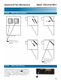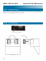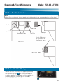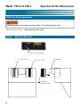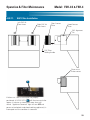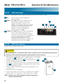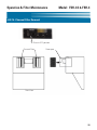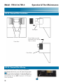
1
Operations & Service Manual
FSH-3.5 & FSH-4
Model: FSH-3.5 & FSH-4
Giles Enterprises, Inc.
ISO 9001 Registered Company • Committed to Quality
2750 Gunter Park Drive West • Montgomery, AL 36109 USA
Phone: 334.272.1457 • Fax: 334.239.4117 • Website: www.gfsequipment.com
Service Hotline (Toll Free): 800.554.4537 (USA & Canada Only)
Form No. 65497 (Release date: 04/09) (Revision Date: 08/10, Rev. B)
LIMITED WARRANTY
•
Subject to the terms and conditions of this Limited Warranty as herein stated, all Giles Enterprises,
Inc., Foodservice Equipment and parts purchased new from an authorized Giles Enterprises, Inc.,
representative are warranted as to defects in material or workmanship for a period of 12 months
from the date of installation, provided, however, that with regard to labor costs in connection with
this warranty, see below. All installations must be made by a qualified installing agency in accordance with all applicable codes and/or regulations in the jurisdiction in which installed. Limited warranty coverage is extended to the original owner only and is void if the unit is resold.
•
During the Limited Warranty period, Giles Enterprises, Inc. will replace or recondition, at its factory,
any part or parts of this unit which Giles Enterprises, Inc. inspectors judge defective, provided the
unit has been subjected to normal usage, properly installed, operated and serviced. This Limited
Warranty does not cover cosmetic damage, and damage due to acts of God, accident, misuse, alteration, negligence, abuse of the Giles Foodservice Equipment or the use of unorthodox repair methods. All parts replaced under this Limited Warranty carry only the unexpired term of this Limited
Warranty. Limited Warranty service may be furnished only by an authorized Giles Enterprises, Inc.,
representative.
•
If Limited Warranty service is requested, Giles Enterprises, Inc., will send factory-authorized service representatives to repair, recondition, replace or inspect units of its manufacture with such labor
being rendered without cost to owner for ninety (90) days from the date of installation. Otherwise,
service, including labor and transportation charges or other expenses, in connection with the
removal or installation of any part or parts supplied under this Limited Warranty, are specified on the
original sales contract between the purchaser and the authorized Giles Enterprises, Inc., representative.
•
Giles Enterprises, Inc. reserves the right to change or improve its equipment and parts in any way
without obligation to alter such equipment or parts previously manufactured.
•
Giles Enterprises, Inc. makes no further warranties, express or implied including implied warranties
of merchantability or fitness for a particular purpose, and has no other obligation or liability not
specifically stated herein.
•
Repair or replacement as provided under this limited warranty is the exclusive remedy. Giles
Enterprises, Inc., shall not be liable for any incidental or consequential damages for breach of any
express or implied warranty on this product, except to the extent prohibited by applicable law. Any
implied warranty of merchantability or fitness for a particular purpose on this product is limited in
duration to the duration of this limited warranty.
•
Used Giles Enterprises, Inc., Foodservice Equipment or parts or Giles Enterprises, Inc., Foodservice
Equipment or parts not purchased from an authorized Giles Enterprises, Inc., representative, carry
no warranties, express or implied.
Table Of Contents
Safety
Model: FSH-3.5 & FSH-4
........................................................v
Safety Overview . . . . . . . . . . . . . . . . . . . . . . . . . . . . . . . . . . . . . . . . . . . . . . . . . . . . . . . . . . . . . . . . . . . . v
Specific Safety Precautions . . . . . . . . . . . . . . . . . . . . . . . . . . . . . . . . . . . . . . . . . . . . . . . . . . . . . . . . . . . vi
1.
Introduction . . . . . . . . . . . . . . . . . . . . . . . . . . . . . . . . . . . . . . . . . . . . . . 1
1-1.
1-2.
1-3.
1-4.
1-4.1.
1-4.3.
1-4.4.
Construction . . . . . . . . . . . . . . . . . . . . . . . . . . . . . . . . . . . . . . . . . . . . . . . . . . . . . . . . . . . . . . 1
Standard Features. . . . . . . . . . . . . . . . . . . . . . . . . . . . . . . . . . . . . . . . . . . . . . . . . . . . . . . . . . 1
Optional Features . . . . . . . . . . . . . . . . . . . . . . . . . . . . . . . . . . . . . . . . . . . . . . . . . . . . . . . . . . 1
Specifications . . . . . . . . . . . . . . . . . . . . . . . . . . . . . . . . . . . . . . . . . . . . . . . . . . . . . . . . . . . . . 2
Overall Dimensions. . . . . . . . . . . . . . . . . . . . . . . . . . . . . . . . . . . . . . . . . . . . . . . . . . . . . . . . . 2
Regulatory Listings . . . . . . . . . . . . . . . . . . . . . . . . . . . . . . . . . . . . . . . . . . . . . . . . . . . . . . . . . 4
Hood Weights . . . . . . . . . . . . . . . . . . . . . . . . . . . . . . . . . . . . . . . . . . . . . . . . . . . . . . . . . . . . . 4
2.
Installation . . . . . . . . . . . . . . . . . . . . . . . . . . . . . . . . . . . . . . . . . . . . . . . 5
2-01.
2-02.
2-03.1.
2-03.2.
2-03.3.
2-04.
2-04.1.
2-04.2.
2-04.3.
2-04.4.
2-04.5.
2-04.6.
2-04.7.
2-04.8.
2-05.
2-05.1.
2-05.2
2-05.3
2-06.
2-06.1.
2-06.2.
2-06.3.
2-06.4.
2-06.5.
Unpacking . . . . . . . . . . . . . . . . . . . . . . . . . . . . . . . . . . . . . . . . . . . . . . . . . . . . . . . . . . . . . . . . 5
Location . . . . . . . . . . . . . . . . . . . . . . . . . . . . . . . . . . . . . . . . . . . . . . . . . . . . . . . . . . . . . . . . . 6
Ceiling Mount Hood Mounting Detail. . . . . . . . . . . . . . . . . . . . . . . . . . . . . . . . . . . . . . . . . . . 6
Hood Skirt Installation . . . . . . . . . . . . . . . . . . . . . . . . . . . . . . . . . . . . . . . . . . . . . . . . . . . . . . 7
Free Standing Mounting Detail. . . . . . . . . . . . . . . . . . . . . . . . . . . . . . . . . . . . . . . . . . . . . . . . 8
Cooking Appliance limitations and clearances . . . . . . . . . . . . . . . . . . . . . . . . . . . . . . . . . . . . 9
Fryer limitations . . . . . . . . . . . . . . . . . . . . . . . . . . . . . . . . . . . . . . . . . . . . . . . . . . . . . . . . . . . 9
Fryer clearances . . . . . . . . . . . . . . . . . . . . . . . . . . . . . . . . . . . . . . . . . . . . . . . . . . . . . . . . . . . 9
Oven limitations . . . . . . . . . . . . . . . . . . . . . . . . . . . . . . . . . . . . . . . . . . . . . . . . . . . . . . . . . . 10
Oven clearances . . . . . . . . . . . . . . . . . . . . . . . . . . . . . . . . . . . . . . . . . . . . . . . . . . . . . . . . . . 10
Griddle limitations. . . . . . . . . . . . . . . . . . . . . . . . . . . . . . . . . . . . . . . . . . . . . . . . . . . . . . . . . 11
Griddle clearances . . . . . . . . . . . . . . . . . . . . . . . . . . . . . . . . . . . . . . . . . . . . . . . . . . . . . . . . 11
Range limitations . . . . . . . . . . . . . . . . . . . . . . . . . . . . . . . . . . . . . . . . . . . . . . . . . . . . . . . . . 12
Range clearances . . . . . . . . . . . . . . . . . . . . . . . . . . . . . . . . . . . . . . . . . . . . . . . . . . . . . . . . . 12
Hood Electrical Requirements . . . . . . . . . . . . . . . . . . . . . . . . . . . . . . . . . . . . . . . . . . . . . . . 13
Electrical Connections . . . . . . . . . . . . . . . . . . . . . . . . . . . . . . . . . . . . . . . . . . . . . . . . . . . . . 13
Routing Power Wires . . . . . . . . . . . . . . . . . . . . . . . . . . . . . . . . . . . . . . . . . . . . . . . . . . . . . . 14
Hood and Appliance Interlock Diagram. . . . . . . . . . . . . . . . . . . . . . . . . . . . . . . . . . . . . . . . . 15
Fire Suppression System Installation . . . . . . . . . . . . . . . . . . . . . . . . . . . . . . . . . . . . . . . . . . 15
Fire Suppression System Routing . . . . . . . . . . . . . . . . . . . . . . . . . . . . . . . . . . . . . . . . . . . . 15
Fire Suppression Fusible Links . . . . . . . . . . . . . . . . . . . . . . . . . . . . . . . . . . . . . . . . . . . . . . . 16
Appliance Nozzles. . . . . . . . . . . . . . . . . . . . . . . . . . . . . . . . . . . . . . . . . . . . . . . . . . . . . . . . . 16
Fire Extinguisher Nozzle Locations. . . . . . . . . . . . . . . . . . . . . . . . . . . . . . . . . . . . . . . . . . . . 17
General Maintenance . . . . . . . . . . . . . . . . . . . . . . . . . . . . . . . . . . . . . . . . . . . . . . . . . . . . . . 17
3.
Overview . . . . . . . . . . . . . . . . . . . . . . . . . . . . . . . . . . . . . . . . . . . . . . . 19
3-01.
3-02.
3-03.
Control Panel . . . . . . . . . . . . . . . . . . . . . . . . . . . . . . . . . . . . . . . . . . . . . . . . . . . . . . . . . . . . 20
Filter Chamber and Exhaust . . . . . . . . . . . . . . . . . . . . . . . . . . . . . . . . . . . . . . . . . . . . . . . . . 22
Accessories (Included) . . . . . . . . . . . . . . . . . . . . . . . . . . . . . . . . . . . . . . . . . . . . . . . . . . . . . 24
iii
Model: FSH-3.5 & FSH-4
Table Of Contents
4.
Operation & Filter Maintenance . . . . . . . . . . . . . . . . . . . . . . . . . . . . 27
4-01.
4-02.
4-02.01.
4-02.02.
4-02.03.
4-02.04.
4-02.05.
4-02.06.
4-02.07.
4-02.08.
4-02.09.
4-02.10.
4-02.11.
4-02.12.
4-02.13.
4-02.14.
4-02.15.
4-02.16.
4-02.17.
4-03.
Hood Operation . . . . . . . . . . . . . . . . . . . . . . . . . . . . . . . . . . . . . . . . . . . . . . . . . . . . . . . . . . 27
Filters and Filter Maintenance . . . . . . . . . . . . . . . . . . . . . . . . . . . . . . . . . . . . . . . . . . . . . . . 27
Ventless Hood Filter Table . . . . . . . . . . . . . . . . . . . . . . . . . . . . . . . . . . . . . . . . . . . . . . . . . . 27
Baffle Filter Removal. . . . . . . . . . . . . . . . . . . . . . . . . . . . . . . . . . . . . . . . . . . . . . . . . . . . . . . 28
Baffle Filter Installation . . . . . . . . . . . . . . . . . . . . . . . . . . . . . . . . . . . . . . . . . . . . . . . . . . . . . 29
Baffle Filter Missing . . . . . . . . . . . . . . . . . . . . . . . . . . . . . . . . . . . . . . . . . . . . . . . . . . . . . . . 29
Baffle Filter Cleaning. . . . . . . . . . . . . . . . . . . . . . . . . . . . . . . . . . . . . . . . . . . . . . . . . . . . . . . 30
Pre-Filter Removal. . . . . . . . . . . . . . . . . . . . . . . . . . . . . . . . . . . . . . . . . . . . . . . . . . . . . . . . . 30
Pre-Filter Installation . . . . . . . . . . . . . . . . . . . . . . . . . . . . . . . . . . . . . . . . . . . . . . . . . . . . . . . 31
Pre-Filter Filter Missing. . . . . . . . . . . . . . . . . . . . . . . . . . . . . . . . . . . . . . . . . . . . . . . . . . . . . 31
Pre-Filter Replacement . . . . . . . . . . . . . . . . . . . . . . . . . . . . . . . . . . . . . . . . . . . . . . . . . . . . . 32
EAC Filter Removal . . . . . . . . . . . . . . . . . . . . . . . . . . . . . . . . . . . . . . . . . . . . . . . . . . . . . . . . 32
EAC Filter Installation . . . . . . . . . . . . . . . . . . . . . . . . . . . . . . . . . . . . . . . . . . . . . . . . . . . . . . 33
EAC Filter Status. . . . . . . . . . . . . . . . . . . . . . . . . . . . . . . . . . . . . . . . . . . . . . . . . . . . . . . . . . 34
EAC Filter Cleaning . . . . . . . . . . . . . . . . . . . . . . . . . . . . . . . . . . . . . . . . . . . . . . . . . . . . . . . . 34
Charcoal Filter Removal . . . . . . . . . . . . . . . . . . . . . . . . . . . . . . . . . . . . . . . . . . . . . . . . . . . . 35
Charcoal Filter Installation . . . . . . . . . . . . . . . . . . . . . . . . . . . . . . . . . . . . . . . . . . . . . . . . . . 36
Charcoal Filter Missing . . . . . . . . . . . . . . . . . . . . . . . . . . . . . . . . . . . . . . . . . . . . . . . . . . . . . 36
Charcoal Filter Replacement. . . . . . . . . . . . . . . . . . . . . . . . . . . . . . . . . . . . . . . . . . . . . . . . . 37
Filter Alarm Chart . . . . . . . . . . . . . . . . . . . . . . . . . . . . . . . . . . . . . . . . . . . . . . . . . . . . . . . . . 37
5.
Hood Cleaning and Maintenance . . . . . . . . . . . . . . . . . . . . . . . . . . . 39
5-1.
5-2.
5-3.
5-4.
5-5.
5-6.
Monthly Interlock Check . . . . . . . . . . . . . . . . . . . . . . . . . . . . . . . . . . . . . . . . . . . . . . . . . . . . 39
Quarterly Hood Cleaning . . . . . . . . . . . . . . . . . . . . . . . . . . . . . . . . . . . . . . . . . . . . . . . . . . . 39
Semi-Annual Fire Suppression System . . . . . . . . . . . . . . . . . . . . . . . . . . . . . . . . . . . . . . . . 40
Annual Fire Suppression System . . . . . . . . . . . . . . . . . . . . . . . . . . . . . . . . . . . . . . . . . . . . . 40
12 Year Fire Suppression System . . . . . . . . . . . . . . . . . . . . . . . . . . . . . . . . . . . . . . . . . . . . . 40
Maintenance and Service Log . . . . . . . . . . . . . . . . . . . . . . . . . . . . . . . . . . . . . . . . . . . . . . . 41
6.
Troubleshooting . . . . . . . . . . . . . . . . . . . . . . . . . . . . . . . . . . . . . . . . . 43
6-1.
Troubleshooting Procedures . . . . . . . . . . . . . . . . . . . . . . . . . . . . . . . . . . . . . . . . . . . . . . . . . 43
Parts List . . . . . . . . . . . . . . . . . . . . . . . . . . . . . . . . . . . . . . . . . . . . . . . 45
7–1.
7-2.
7-3.
7-4.
7-5.
7-6.
iv
Parts Ordering and Service Information . . . . . . . . . . . . . . . . . . . . . . . . . . . . . . . . . . . . . . . . 45
Component Drawer . . . . . . . . . . . . . . . . . . . . . . . . . . . . . . . . . . . . . . . . . . . . . . . . . . . . . . . 47
Front View -Doors and Panel removed . . . . . . . . . . . . . . . . . . . . . . . . . . . . . . . . . . . . . . . . . 49
Baffle Filters and Switches . . . . . . . . . . . . . . . . . . . . . . . . . . . . . . . . . . . . . . . . . . . . . . . . . . 51
Doors and Front Panel (Ceiling Mounted). . . . . . . . . . . . . . . . . . . . . . . . . . . . . . . . . . . . . . . 53
Doors and Front Panel (Free-Standing) . . . . . . . . . . . . . . . . . . . . . . . . . . . . . . . . . . . . . . . . . 55
Safety
Model: FSH-3.5 & FSH-4
Safety
Safety Overview
The instructions contained in this manual have been prepared to aid you in learning the proper procedures
for installing and servicing your unit.
Throughout this manual, safety precautions are identified through the use of the safety alert symbol and
three signal words: DANGER, WARNING, and CAUTION. All safety alert information precedes the
step(s) to which they apply. Suggested, recommended, or other noteworthy information is identified
through the use of NOTES. Additionally, certain words are used to indicate a specific meaning or to add
emphasis.
The following words are used as indicated throughout the manual:
Shall: understood to be mandatory.
Should: understood to be advisory.
May: understood to be permissive.
Will: indicates a future event/condition to occur.
! or !
(Safety Alert Symbol)
Used in conjunction with signal words (DANGER, WARNING, or CAUTION) to alert you of potential personal injury hazards, immediately preceding precautionary measures that pertain to subsequent step(s).
Obey all safety messages that follow this symbol to avoid possible injury or death. Failure to adhere to
safety precautions identified by the safety alert symbol may also void the warranty.
!
DANGER
• Indicates an imminently hazardous situation which, if not avoided, will result in death or serious injury.
Use of this is limited to the most extreme situations.
! WARNING
• Indicates a potentially hazardous situation which, if not avoided, could result in death or serious injury.
! CAUTION
• Indicates a potentially hazardous situation which, if not avoided, may result in minor or moderate injury.
Also used to alert against unsafe practices.
CAUTION
• When used without the safety alert symbol, CAUTION indicates a potentially hazardous situation
which, if not avoided, may result in equipment/property damage, and void the warranty.
NOTE:
• Identifies suggested, recommended, or other noteworthy information.
v
Model: FSH-3.5 & FSH-4
Safety
Specific Safety Precautions
For your safety, please observe the following precautions when operating or servicing your Ventless Hood
equipment. Read the following important safety information to avoid personal injury and/or damage to the
equipment or property.
!
DANGER
• Always disconnect the source of the main power before removing the service entrance box cover.
• Failure to ensure the Power switch is in the “OFF” position during servicing and when replacing filters
could result in equipment damage, electrical shock and/or personal injury.
• Failure to comply with these DANGER notices will result in death or serious injury, equipment/property
damage, and void the warranty.
! WARNING
• DO NOT use or store flammable liquids or materials that produce flammable vapors in the vicinity of
this or any other appliance!
• Consult a qualified electrician to ensure all electrical specifications have been met and the unit is properly grounded.
• Before installing or servicing this equipment, read the contents of this manual thoroughly.
• Improper installation, adjustment, alteration, service or maintenance could result in death or serious
injury, equipment/property damage, and void the warranty.
• Failure to comply with these WARNING notices could result in death or serious injury and
equipment/property damage.
vi
Safety
Model: FSH-3.5 & FSH-4
! CAUTION
• Maintain a minimum clearance of 14” (355.6mm) between the hood outlet and the ceiling or any
obstruction above the hood. 18” (457.2mm) is recommended for best performance.
• Exercise care when lifting or moving the unit. See Section 1-4.4 for Hood weights.
• Exercise care when removing the wooden crate from around the unit.
! CAUTION
• DO NOT operate the unit unless you fully understand the components and their intended function.
• Be careful not to bend the fins or break the ionizer wires on the Electrostatic Air Cleaner (EAC).
Doing
so will prevent the EAC from working properly and cause a shutdown of power to the appliance being
used with the hood.
• Failure to comply with these CAUTION notices may result in minor or moderate injury, equipment/property damage, and void the warranty.
CAUTION
• The electronic components of the Control Panel are impact-sensitive.
Exercise care around the Control
Panel to maintain proper operation.
• Do not attempt to dry the EAC after cleaning by installing it and running the hood to force air dry or by
running an appliance below to heat dry. This could potentially damage the EAC system leading to failure and voiding the warranty. The filter must air dry at ambient room temperature, preferably overnight.
• During cleaning of Hood.
•• DO NOT steam clean.
•• DO NOT use products containing chlorine.
•• DO NOT use abrasive products, steel wool or scouring pads.
• Failure to comply with these CAUTION notices may result in equipment/property damage and void the
warranty.
vii
Model: FSH-3.5 & FSH-4
Safety
NOTE:
• If upon receipt, the palletized unit shows any signs of damaged, immediately inspect the entire
Ventless Hood and the included accessories, and promptly notify the freight company of any damages.
• To aid the electrician, an electrical wiring diagram is attached inside the back cover of this manual.
Refer to the wiring diagram during installation or servicing. A wiring diagram is also attached to the
inside of the filter access door.
• Comply with all appropriate state and/or local heath regulations regarding the cleaning and sanitation of
equipment.
• For cleaning areas with excessive particulate build up, a mild bio-degradable non-toxic degreaser (such
as Clear Magic or Simple Green) may be used.
• Always ensure the unit is electrically grounded and installed in accordance with local codes, or in the
absence of local codes, in accordance with the National Electrical Code ANSI/NFPA No. 70-1984.
NOTE:
• The decibel level of the hood when operating is approximately 73 dB.
NOTE:
• A HVAC specialist may be required for installations to confirm proper air
exchange and the heat load capabilities of the on-site AC system.
• Exhaust ventilation is recommended for areas in which recirculating hoods are used. We recommend
50 CFM per lineal ft. of hood.
•This amount could vary based on local codes and the site specific installation requirements.
viii
Introduction
1.
Model: FSH-3.5 & FSH-4
Introduction
Congratulations on the purchase of a new FSH-3.5 or FSH-4 Giles Ventless Hood System manufactured by
Giles Enterprises, Inc., Montgomery, Alabama (USA), hereafter referred to as "Giles". These two models
are available in either ceiling mounted or free-stand mounted versions. The stand mounted version is
available in a 72” or 78” height (measured from the floor to the bottom edge on the hood skirt).
Proper care and maintenance of this unit will ensure years of trouble-free service and to help protect your
investment in this equipment, we recommend taking a few moments to familiarize yourself with the
installation, cleaning, and maintenance procedures described in this manual. We urge you to read these
instructions before installing or using this hood. Adherence to these recommended procedures will
minimize potential for costly downtime and equipment repairs. Please retain this manual for future
reference.
1-1. Construction
The Ventless Hood System exterior is constructed of stainless steel.
1-2. Standard Features
Control Panel
• Two LED light clusters indicate the status of the left and right EAC filters.
• “Appliance Powered” light indicates that power is being supplied to the interlocked appliance(s) under
the hood.
• “Filter Missing” light indicates that one (or more) Baffle filter, Pre-filter, and/or Charcoal filter is missing
or installed improperly.
• “Filter Clogged” light indicates that the Baffle filters, Pre-filters, and/or Charcoal filters are possibly
clogged and require attention to ensure proper hood performance.
Filters
•
•
•
•
Baffle Filters - capture large grease particles in the air stream.
Pre-Filters - capture the smaller grease particles.
Electronic Air Cleaners (EAC) - capture smoke & fine particle air contaminates.
Charcoal Filters - help eliminate cooking odors.
1-3. Optional Features
Inter-Locking Start System (ILS)
• Inter-Locking Start System (ILS) - Should there be a power interruption to the the hood, this system will
not allow the Hood and the Appliance(s) below it to restart without the attendance of an operator. This
system is required by code in some cities and/or states. Please consult with your local code officials to
see if this option is required.
Floor Stand Mount
• 72” or 78” high stand mounts are available instead of the standard ceiling hung mount (*height
measured from floor to bottom edge of skirt).
1
Model: FSH-3.5 & FSH-4
1-4. Specifications
1-4.1. Overall Dimensions for FSH-3.5 / 4 (Ceiling Mount Option)
DIM
(A)
(B)
(C)
FSH-3.5
42-11/16 [1084.4]
37-11/16 [958.0] C to C
42-5/8 [1081.9]
(A)
(B)
(C)
2
FSH-4
48-11/16 [1236.7]
43-11/16 [1109.7] C to C
48-5/8 [1235.1]
Introduction
Introduction
Model: FSH-3.5 & FSH-4
1-4.2. Overall Dimensions for FSH-3.5 / 4 (Free Standing Option)
DIM
(A)
(B)
(C)
FSH-3.5
42-11/16 [1084.4]
39-1/16 [991.7]
44-3/8 [1126.6]
FSH-4
48-11/16 [1236.7]
45-1/16 [1144.6]
50-3/8 [1279.5]
(D)
(E)
(with 72” Stand Mt)
72 [1828.8]
115-5/8 [2936.9]
(with 78” Stand Mt)
78 [1981.2]
121-5/8 [3089.3]
(A)
(E)
(D)
(B) INSIDE
(C)
INCHES [MILLIMETERS]
3
Model: FSH-3.5 & FSH-4
Introduction
1-4.3. Regulatory Listings
1-4.4. Hood Weights
4
Hood
Crated Weight
Uncrated Weight
FSH-3.5 (Ceiling Mt.)
664 lbs [302 kg]
464 lbs [211 kg]
FSH-3.5 (Stand Mt.)
733 lbs [333 kg]
553 lbs [251 kg]
FSH-4 (Ceiling Mt.)
724 lbs [328 kg]
524 lbs [243 kg]
FSH-4 (Stand Mt.)
793 lbs [368 kg]
613 lbs [284 kg]
Installation
Model: FSH-3.5 & FSH-4
2. Installation
This section summarizes the procedures necessary to install your new FSH-3.5 or FSH-4 Hood. Before
installing or servicing this equipment, please read the contents of this manual thoroughly. Following these
procedures will help ensure a safe and proper installation.
NOTE:
• A HVAC specialist may be required for some installations to confirm proper
air exchange and the heat load capabilities of the on-site AC system.
• Exhaust ventilation is recommended for areas in which recirculating hoods are used. We recommend
50 CFM per lineal ft. of hood.
•This amount could vary based on local codes and the site specific installation requirements.
2-01. Unpacking
Your Ventless Hood should arrive palletized with a wooden protective frame, wrapped in machine applied
stretch-wrap, and secured to by means of high-tensile plastic strapping. Perform the following steps to
unpack the unit:.
1. Position the palletized unit in an area that has sufficient space for unpacking.
!! IMPORTANT NOTE:
• If the palletized unit shows any signs of damage, immediately inspect the equipment and other packed
components, and notify the freight company of any and all damages.
2. Cut and remove stretch-wrap and all strapping.
3. Use a hammer and pry-bar to remove the wooden crate from around the unit
! CAUTION
•
•
•
Use suitable equipment to lift the hood and carefully move it away from the pallet ... see Section 1-4.4
for hood weights. Take precautions not to damage to the hood’s bottom skirting. If possible, it is
advisable to rig and lift the hood from the topside, utilizing the hood’s hanging brackets.
Exercise care when removing the wooden framing from around the unit.
Failure to comply with these CAUTION notices may result in minor or moderate injury, equipment or
property damage, and void the warranty.
5
Model: FSH-3.5 & FSH-4
Installation
2-02. Location
NOTE:
•The decibel level of the hood when operating is approximately 73 db.
! CAUTION
• DO NOT MODIFY, ALTER OR ADD ATTACHMENTS TO THIS EQUIPMENT
NOTE:
• A HVAC specialist may be required for some installations to confirm proper
air exchange and the heat load capabilities of the on-site AC system.
• Exhaust ventilation is recommended for areas in which recirculating hoods are used. We recommend
50 CFM per lineal ft. of hood.
•This amount could vary based on local codes and the site specific installation requirements.
1. Do not obstruct the exhaust air outlet. Maintain a minimum clearance of 14 inches (355.6mm)
between the air outlet and ceiling, or any obstruction.
2. Ensure intended mounting site is structurally sound and capable of supporting the hood’s weight.
See Section 1-4.4 for hood weights
2-03.1
Hood Mounting Detail (Ceiling Mount)
1/2” All-Thread
1/2” Hex Nut
1/2” Lock Washer
1/2” Flat Washer
1/2” Flat Washer
1/2” Lock Washer
1/2” Hex Nut
1. Ensure the hood is level, left to right and front to back.
2. Ensure all mounting fasteners are tight and secure.
6
Installation
2-03.2
Model: FSH-3.5 & FSH-4
Hood Skirt Installation (Ceiling Mount)
NOTE:
•
Hood Skirts MUST be installed for proper air capture.
1. Apply a bead of Hi-Temp Silicone (included) to the top flanges of both Side Skirts.
2. Attach Left and Right Side Skirts to hood with enclosed fastners (do not tighten completely).
3. Apply a bead of the Hi-Temp Silicone to the top flange of the Rear Skirt.
4. Attach Rear Skirt to hood with enclosed fastners (do not tighten completely) .
5. Fasten Left and Right Skirts to Rear Skirt.
6. Completely tighten all fastners and wipe any excess silicone from the assembled Skirt.
NOTE: Peel all protective film from parts before assembling.
(21) 1/4-20 Nut
Bead of Hi-Temp
Silicone (enclosed)
Bead of Hi-Temp
Silicone (enclosed)
(21) 1/4-20 x 3/8 Screw
Rear Skirt
Left Skirt
Right Skirt
7
Model: FSH-3.5 & FSH-4
2-03.3
STEP 1
STEP 2
8
Hood Mounting Detail (Free-Standing)
Installation
Installation
Model: FSH-3.5 & FSH-4
2-04. Cooking Appliance Limitations and Clearances
2-04.1.
Fryer Limitations (Electric Appliances Only)
Hood
Max. Temp.
Max. kW Input
Max.
Shortening
Capacity
Max Cooking
Surface (per
Fryer)
Max Cooking
Surface (Total
all Fryers)
FSH-3.5 / 4
400
20(1)/40 Total
20 Gal.
576 Sq. In.
576 Sq. In.
2-04.2.
Fryer Clearances (side-to-side overhang requirement does not apply with
Free-standing Mount model)
Inches [Millimeters]
9
Model: FSH-3.5 & FSH-4
2-04.3.
2-04.4.
Oven Limitations (Electric Appliances Only)
Hood
Max. Temp.
Max. kW Input
(Total all Ovens)
FSH-3.5 / 4
500
55
Oven Clearances
Inches [Millimeters]
10
Installation
Installation
2-04.5.
Model: FSH-3.5 & FSH-4
Griddle Limitations (Electric Appliances Only)
Hood
Max. Temp.
Max. kW Input
Max Cooking Surface
FSH-3.5 / 4
400
25
42 X 42
2-04.6.
Griddle Clearances (side-to-side overhang requirement does not apply with
Free-standing Mount model)
Inches [Millimeters]
11
Model: FSH-3.5 & FSH-4
2-04.7.
Range Limitations (Electric Appliances Only)
Hood
Max. Temp.
Max. kW Input
Max Burners
FSH-3.5 / 4
400
25
8
2-04.8.
Range Clearances (side-to-side overhang requirement does not apply with
Free-standing Mount model)
Inches [Millimeters]
12
Installation
Installation
Model: FSH-3.5 & FSH-4
2-05. Hood Electrical Requirements
! WARNING
•
Consult a qualified electrician to ensure all electrical specifications have been met and that the unit is properly
grounded.
•
Improper installation, adjustment, alteration, service or maintenance could result in death or serious injury,
equipment/property damage, and void the warranty.
Hood Electrical Requirements
Unit
Voltage
Hz
Phase
Amps
Breaker
FSH-3.5 & 4
208 or 240
60
1
15
20
2-05.1.
Electrical Connections
1.
Install appropriate Circuit Breaker in Main Breaker Box (See Section 2-05).
2.
Connect appropriate size wire from hood to the main breaker.
3.
Re-install Service Panel.
4.
Turn Main Breaker on.
5.
Press the Hood power switch to the ON position. If ILS, press and hold the “Push to Start” button
for 5 secs after power is on.
13
Model: FSH-3.5 & FSH-4
2-05.2
Routing Power Wires
2-05.3
Hood and Appliance Interlock Diagram
14
Installation
Installation
Model: FSH-3.5 & FSH-4
2-06. Fire Suppression System Installation
It is a requirement that the Giles FSH-3.5 / 4 Ventless Hood System be protected by a UL Listed fire
suppression system. Installation must be performed by an Authorized Fire Suppression Agent in
accordance with the system listing.
The FSH-3.5 / 4 hood system is pre-piped at the factory and contains supply line, plenum nozzles and
fusible link brackets. Appliance nozzles and drop-downs are not included. The hood has been designed
to accommodate either left or right side hook-up. The electrical switch requirements are identical to those
listed in the Ansul R-102 Installation Manual with the hood system acting as the customer supplied
switch.
1.
Use Ansul No. 56922-1W Appliance Nozzles, No. 56927 Plenum Nozzles and Ansul No. 56811
Fusible Link 165ºF (74ºC).
2.
Appliance nozzles shall be positioned 11" [279.4mm] below the lowermost front edge of the hood.
3.
The use of both appliance nozzles is required at all times.
4.
A manual pull station for the Fire System is to be installed and located in a path of exit or egress.
The pull station must be clearly marked and easily accessible.
5.
Regulated Release Assembly shall be the mechanical type (Ansul P/N 79290).
2-06.1.
Fire Suppression System Routing
Fusible Link
Connection
Fire Extinguisher Nozzle
Connection
Regulated Release
Assembly (Ansul
P/N 79290)
Manual Pull
Note -System may be located and connected on the left or right
of the hood.
15
Model: FSH-3.5 & FSH-4
2-06.2.
Installation
Fire Suppression Fusible Links
285 F Degree
(Factory installed)
165 F Degree
(Ansul P/N 56811)
165 F Degree
(Ansul P/N 56811)
165 F Degree
(Ansul P/N 56811)
2-06.3.
Appliance Nozzles
Center Nozzles over cooking
surface(s)
Appliance Nozzle, (2) minimum,
Sized and positioned by Local
Authorized Fire Suppression
Agency
(Pipe & nozzles supplied by
Customer)
16
Installation
2-06.4.
Fire Extinguisher Nozzle Locations
Plenum Nozzle
(Ansul P/N 56925-1/2N)
(Factory installed)
Appliance Nozzle, (2) minimum,
Sized and positioned by Local
Authorized Fire Suppression
Agency
(Supplied by Customer)
2-06.5.
Model: FSH-3.5 & FSH-4
Plenum Nozzle
(Ansul P/N 56922-1W)
(Factory installed)
Plenum Nozzle
(Ansul P/N 56925-1/2N)
(Factory installed)
General Maintenance
The fire extinguishing system should be maintained as outlined in the Standard for Wet Chemical
Extinguishing Systems, NFPA 17A and in accordance with the instructions of the system’s installer.
Please contact a local Authorized Fire Suppression Agent or Ansul Dealer for maintenance, troubleshooting and repairs.
General Maintenance of the fire suppression system is very important. Inspect and maintain as follows:
Servicing and inspection of the fire suppression system is to be conducted by qualified fire protection
technicians. As a minimum, field inspection of the fire suppression system is to be performed semiannually. Such maintenance shall consist of the following:
1.
Confirm that the hazard has not changed.
2.
Verify that system pressure is nominal.
3.
Inspect the soundness of the discharge spray nozzles and fusible links.
4.
Ensure the system is properly located with respect to the appliance.
5.
Verify the date the unit was manufactured.
6.
Check to be sure the service tag is attached indicating what service was performed and when
performed.
*Ansul is a registered trademark.
17
Model: FSH-3.5 & FSH-4
NOTES:
18
Installation
Overview
Model: FSH-3.5 & FSH-4
3. Overview
The following section provides a brief overview of the components, functions, and accessories of the
FSH-3.5 / F S H - 4 Series hood. Please review this section carefully before proceeding any further.
Hood Exhaust Duct
Right Filter
Chamber
Figure 3-2.
Left Filter
Chamber
Figure 3-2.
Control Panel
Figure 3-1.
Hood Skirt
19
Model: FSH-3.5 & FSH-4
Overview
3-01. Control Panel
10
9
8
7
* ILS Only
20
3
1
6
5
4
6
5
4
2*
Overview
Model: FSH-3.5 & FSH-4
3-01. Control Panel
Item
Description
1
Light Switch
2*
PUSH to START
Button
3
Power Switch
“CHECK” LED Indicator
4
(Right & Left EAC’s)
Function
Used to turn the hood light on and off.
After the Power Switch is in the “ON” position, push and
hold down “PUSH to START” Button for 5 seconds. (Used
only in units with Inter-Locking Start (ILS) system.
The Power Switch is a two-position Switch. Move the switch
upward to the “ON” position for operation.
The “Check” Indicator Light will turn on when the EAC
becomes shorted. (EAC needs cleaning or repair).
5
“WASH” LED Indicator
(Right & Left EAC’s)
The “Wash“ Indicator Light will come on when the EAC
becomes excessively dirty. DO NOT use this light as a signal
for routine cleaning of the EAC. Failure to clean the EAC daily
will significantly decrease the life of the charcoal filter and
possibly damage the EAC power supply. Clean the EAC daily
for best performance.
6
“ON” LED Indicator
(Right & Left EAC’s)
The “ON” Indicator Light will turn on when the Electronic Air
Cleaner (EAC) power supply is on.
7
Charcoal or Baffle Filter
Clogged Light
The “Charcoal or Baffle Filer Clogged” Light will turn on when
the Grease Baffle Filter, Pre-filter, or Charcoal Filter is
dirty/clogged.
8
Charcoal or Baffle Filter
Missing Light
The “Charcoal or Baffle Filter Missing Light” illuminates when
either Charcoal, Pre-Filter, or Baffle filter is missing or incorrectly installed.
9
10
The “Appliance Powered Light”will turn on to signify appliance
Appliance Powered Light power when all filters are installed correctly and none are
clogged.
Hood Powered Light
* Inter-Locking Start (ILS) Only
The “Hood Powered Light” will turn on when both of the filter
doors are closed properly and power switch is “on.” If
equipped, ILS button must also be depressed.
21
Model: FSH-3.5 & FSH-4
Overview
3-02. Filter Chamber and Exhaust
1
1
7
3
4
4
5
5
3
6
Not shown
8 Not shown
2
22
Not shown
Overview
Model: FSH-3.5 & FSH-4
3-02. Filter Chamber and Exhaust
Item
Description
1
(2) Hood Filter Door
2
(2) Baffle Filter
Function
Used to access the Pre-Filter, EAC and Charcoal Filters. The
door must be closed and latched for the unit to operate.
Baffle Filters are the first stage of the grease extraction and aircleaning system of this unit. These filters are easily removed
for daily cleaning. To prevent contact with electrical parts
and avoid electrical shock, DO NOT remove the Baffle
Filter(s) while the hood is operating. The Baffle Filter
should be cleaned daily.
(2) Pre-Filter
Pre-Filters remove additional grease-laden vapors from the air
stream. To prevent contact with electrical parts and avoid
electrical shock, DO NOT remove the Pre-Filter(s) while the
hood is operating. NEVER attempt to clean and re-use the
Pre-Filters ... Replace with new filters weekly.
EAC Filter
(Left and Right)
EAC Filters are electrostatic devices that remove grease vapor
and smoke generated by the appliance during cooking. To prevent contact with electrical parts and avoid electrical
shock, DO NOT remove the EAC Filter while the hood is
operating ... The EAC should be cleaned daily.
5
(2) Charcoal Filter
Charcoal Filter helps to eliminate cooking odors. These Filters
should be replaced monthly. To prevent contact with electrical parts and avoid electrical shock, DO NOT remove the
Charcoal Filter while the hood is operating. NEVER
attempt to clean and re-use the Charcoal Filters ... Replace
with new filters every 30 days.
6*
Hood Skirt
3
4
7*
Exhaust Outlet
8*
Grease Drip Cup
The Hood Skirt helps contain and capture grease laden
vapors produced by the cooking appliance.
The Exhaust Outlet located on front of the unit, exhausts the
filtered air back into the room. A minimum clearance of 14”
must be maintained between the top of the Exhaust
Outlet and the Ceiling, or other obstruction, for proper
air flow.
The Grease Drip Cup is used to catch grease condensate
generated at the Baffle Filters. This cup must be emptied and
cleaned daily.
* Not shown
23
Model: FSH-3.5 & FSH-4
3-03.
Overview
Accessories (Included)
Part
Description/Part Number
(2) Baffle Filter
P/N 40943
(2) Pre-Filter
P/N 91707
EAC Filter
P/N 20521 (LEFT)
P/N 20520 (RIGHT)
24
Function
Removes large particle
contaminant from the air.
Removes additional greaseladen vapors from the air.
Removes smoke and small
particle contaminant from the
air.
Overview
Model: FSH-3.5 & FSH-4
3-03. Accessories (Included)
Part
Description/Part Number
Function
(2) Charcoal Filter
P/N 31964
Helps remove odors from the
air
EAC Soak Tank
P/N 39327
Used for soaking and cleaning
EAC filter.
25
Model: FSH-3.5 & FSH-4
Notes:
26
Overview
Operation & Filter Maintenance
Model: FSH-3.5 & FSH-4
4. Operation & Filter Maintenance
This section describes Hood operation and filter maintenance.
4-01. Hood Operation
Starting the Ventless Hood ... Make sure all Filters are in place and filter access doors are closed before
attempting to operate the unit. NOTE: The hood will NOT power-up if either filter door is open.
1. Place the Power Switch 1 to the ON position, (if ILS
model, press and hold the “Push & Hold to Start” Button
5
1
4
3
3
2 for 5 seconds). The EAC ON light 3 will illuminate
and the “Appliance Powered” light
5 will turn ON.
The cooking appliance under the hood, which is
interlocked with the hood may now be turned on.
2. Press the Light Switch 4 to the ON position to turn on
the under-hood lights.
* ILS Only
*2
4-02. Filters and Filter Maintenance
Filter System operation, cleaning and maintenance schedule
4-02.01.
Ventless Hood Filter Table
Filter
When to clean or
replace
How to remove
How to clean
How to install
Baffle Filter
Clean daily
Section 4-02.02.
Section 4-02.05.
Section 4-02.03.
Pre-Filter
Replace weekly
Section 4-02.06.
Never clean,
Replace Only
Section 4-02.09.
Section 4-02.07.
EAC Filter
Clean daily
Section 4-02.10.
Section 4-02.13.
Section 4-02.11.
Charcoal Filter
Replace every 30
days
Section 4-02.14.
Never clean,
Replace Only
Section 4-02.17.
Section 4-02.15.
Ultra Violet Lamp
(If equipped)
Clean every 30
days
Replace annually
Section 4-02.19
Section 4-02.18
Section 4-02.20
27
Model: FSH-3.5 & FSH-4
4-02.02.
Operation & Filter Maintenance
Baffle Filter Removal
1
Place in OFF position
2
4
3
28
Operation & Filter Maintenance
4-02.03.
Model: FSH-3.5 & FSH-4
Baffle Filter Installation
2
1
Front View
Position Filter w/
Baffles in a vertical
position
3
Switch Arm must
be actuated by the
Baffle Filter as
shown
4-02.04.
Baffle Filter Missing
If either Baffle Filter is missing, or not positioned
correctly, the Filter Missing Light 1 will illuminate
and power to cooking appliance is interrupted until
the condition is corrected (Appliance Powered light
will turn OFF). See Section 4-2.03 Baffle Filter
Installation.
1
29
Model: FSH-3.5 & FSH-4
4-02.05.
Operation & Filter Maintenance
Baffle Filter Cleaning
Grease Baffle Filters should be cleaned daily. Place them in sink and clean with a mild bio-degradable
degreaser. Dry filters thoroughly and reinstall in the unit.
4-02.06.
Pre-Filter Removal
1
Place in OFF position
Pre-Filter
Front View
30
Door open
Operation & Filter Maintenance
4-02.07.
Model: FSH-3.5 & FSH-4
Pre-Filter Installation
NOTE:
• When filters are changed, always record the installation date in the space provided on the filter label.
Pre-Filter
Paper Side
Paper Side
Metal Mesh Side
Door open
Pre-Filter
Switch Roller must
be actuated by the
Pre-Filter as shown
Front View
Close Door
4-02.08. Pre-Filter Filter Missing
If either Pre-Filter is missing or not properly positioned,
the Filter Missing Light 1 will illuminate and power
to cooking appliance is interrupted until the condition is
corrected (Appliance Powered light will turn OFF).
Section 4-02.07 Pre-Filter Installation.
1
31
Model: FSH-3.5 & FSH-4
Operation & Filter Maintenance
4-02.09. Pre-Filter Replacement
! WARNING
• NEVER attempt to clean and re-use the Pre-Filter.
This could damage the unit.
Replace Pre-Filters weekly ... Replacement Part No. 91707.
4-02.10.
EAC Filter Removal
1
Left EAC Filter
Place in OFF position
Right EAC Filter
EAC Filter
Folding Handle
32
Door open
Operation & Filter Maintenance
4-02.11.
Model: FSH-3.5 & FSH-4
EAC Filter Installation
Left EAC Air
Flow Arrow
Right EAC Air
Flow Arrow
Filter Contact
Plate
Hood Contact
Plate
EAC alignment
Pin
EAC Filter
Folding Handle
Plates must
make contact
1
If either EAC Filter is missing or not properly
positioned, all 3 EAC LED’s 1 will illuminate and after
approx. 2 minutes an intermittent tone alarm will
sound. “Appliance Powered” light will turn OFF and
power to interlocked under-hood cooking appliance(s) is
interrupted until the condition is corrected
33
Model: FSH-3.5 & FSH-4
4-02.12.
Operation & Filter Maintenance
EAC Filter Status
Three LED indicator lights on the Control Panel display the status of each EAC Filter.
1 ON
The EAC Filter is in place, powered and
operating properly..
2 WASH
When ON, indicates the collection fins are
becoming excessively dirty and must be
cleaned. After approx. 2 minutes in this
condition, an intermittent tone alarm will sound
and power to interlocked under-hood cooking
appliance(s) will be interrupted until the
condition is corrected. The “Appliance
Powered” light will turn OFF.
3
2
1
1
2
3
3 CHECK When ON, indicates the Filter is not operating.
There is either a poor connection at the
contacts or the filter is damaged. After approx.
2 minutes in this condition, an intermittent tone
alarm will sound and power to interlocked
under-hood cooking appliance(s) will be
interrupted until the condition is corrected. The
“Appliance Powered” light will turn OFF.
4-02.13.
EAC Filter Cleaning
The EAC Filter should be cleaned daily.
! CAUTION
• Do not bend the fins or break the ionizer wires on the EAC as this will prevent the electrostatic
collecting cell from performing properly and potentially void the warranty.
1.
Add 1/2 gal of a mild degreaser, such as “Simple Green” or “Clean Magic”,
to the Soak Tank 1 ... add water to fill line (X’s) and mix.
2. Holding the cell by the contact plate 2 , carefully lower the EAC 3
into the mixed degreasing solution.
2
3
3. Allow the EAC to soak for 20 to 30 minutes. Grasping it by the contact
plate 2 , lift and agitate vigorously up and down in the solution several
times to dislodge grease residue.
4. Carefully remove the EAC from the tank and rinse thoroughly in a sink
using hot water.
5. Allow the cell to air dry, thoroughly.
6. Inspect cell for broken wires or bent fins, Have broken wires replaced
promptly. Bent fins may be gently straightened by hand, if needed.
NOTE: The EAC cell is NOT designed to withstand washing in
commercial dishwashers.
34
1
Operation & Filter Maintenance
Model: FSH-3.5 & FSH-4
4-02.14. Charcoal Filter Removal
1
Place in OFF position
Charcoal Filter
Door open
Front View
35
Model: FSH-3.5 & FSH-4
Operation & Filter Maintenance
4-02.15. Charcoal Filter Installation
Door open
Blue Side
Charcoal Filter
Front View
Switch Roller must be
actuated by the Charcoal
Filter as shown
Close Door
4-02.16. Charcoal Filter Missing
If either Charcoal Filter is missing or not properly
positioned and the unit is on, the Filter Missing Light
1 will illuminate and power to cooking appliance is
interrupted until the condition is corrected (Appliance
Powered light will turn OFF). Section 4-2.15 Charcoal
Filter Installation.
1
36
Operation & Filter Maintenance
Model: FSH-3.5 & FSH-4
4-02.17. Charcoal Filter Replacement
! WARNING
• NEVER attempt to clean and re-use the Charcoal Filter.
This could cause damage to the unit.
Replace the Charcoal Filter every 30 days. Use Replacement Part No. 31964.
Please take the time to record installation date in space provided on the new filter label.
4-03.
Filter Alarm Chart
Alarm Sound
What will happen
Filter
affected
Cause
Solution
See Section
Continuous tone
Alarm sounds, “Clogged Filter”
4-02.15. &
lamp illuminates and power to the
Charcoal
4-02.17.
appliance is shutdown, “Appliance
Filter dirty Replace Filter
or
or
Powered” light is OFF.
Pre-Filter
4-02.07 &
(If ILS model, the hood fan will also
4-02.09
shutdown)
Continuous tone
Alarm sounds, “Clogged Filter”
lamp illuminates and power to the
appliance is shutdown, “Appliance
Powered” light is OFF.
(If ILS model, the hood fan will also
shutdown)
Baffle
Filter dirty Clean Filter
4-02.03. &
4--02.05
Intermittent tone
“Check” and/or “Wash” LED’s will
illuminate, alarm sounds, after
approx. 2 minutes, power to the
appliance is shutdown, “Appliance
Powered” light is OFF.
(If ILS model, the hood fan will also
shutdown)
E.A.C.
Filter dirty Clean Filter
4-02.11. and
4--02.13
37
Model: FSH-5 & FSH-6
Notes:
38
Operation & Filter Maintenance
Hood Cleaning and Maintenance
Model: FSH-3.5 & FSH-4
5. Hood Cleaning and Maintenance
This Section describes cleaning and maintaining the Hood System. Attention to these procedures will
help ensure the hood remains efficient over time.
A Maintenance & Service Log is provided in this manual, see Section 5-6.
5-1.
Monthly Interlock Check
The Giles Ventless Hood System is designed with various interlock devices to ensure the unit operates in a
safe and effective manner. These interlocks should be tested MONTHLY as described below. Use the
Maintenance & Service Log and place a check in the box that corresponds to each function test. If a
problem is found call your service representative.
1.
Baffle Filter Check: Place power switch in the OFF position, remove the left-side Baffle Filter ... turn power
ON. “Filter Missing Light” should be illuminated and “Appliance Powered” light should be OFF. Turn power
OFF and reinstall the Grease Baffle Filter. Follow the same procedure to check the right-side Filter.
2.
Pre-Filter/Door Interlock Check: Turn power switch ON ... with Hood running, slightly open the Filter
Access door ... confirm Hood shutdown when door is opened ... turn power switch OFF. Remove the leftside Pre-Filter and close door ... turn power ON. “Filter Missing Light” should be illuminated and “Appliance
Powered” light should be OFF. Turn power OFF and reinstall Pre-Filter. Follow the same procedure to check
the right-side Pre-Filter.
3.
EAC Filter Check: Place power switch in the OFF position, remove the left-side EAC Filter and close door ...
turn power ON. Wait 2 minutes ... intermittent alarm should sound and “Appliance Powered” light should be
OFF. Turn power switch OFF and reinstall EAC Filter. Follow the same procedure to check right-side EAC
Filter.
4.
Charcoal Filter Check: Place power switch in the OFF position, remove the left-side Charcoal Filter and
close door ... turn power ON. “Filter Missing Light” should be illuminated and “Appliance Powered” light
should be OFF. Turn power switch OFF and reinstall Charcoal Filter. Follow the same procedure to check
the right-side Charcoal Filter.
5.
Filter Clogged Check: Place Hood power switch in the ON position. The blower will start and a continuous
tone alarm should sound for 2 to 8 seconds until the blower reaches speed, then silence. Check appliance(s)
power during this time; there should be no power supplied to appliance(s) until the alarm silences. If the
alarm tone does not sound, fails to silence, and/or the appliance(s) fails to come on or comes on before the
alarm silences, contact service agent and have the Clogged Filter interlock checked. Return Hood power
switch to the OFF position.
5-2.
Quarterly Hood Cleaning
To maintain effectiveness and performance, the hood must be cleaned, at a minimum, every 3 months.
Disconnect power from the unit, preferably at a breaker. Remove all filters from the hood. Using soft
cloth, sponge or towel, and a mild bio-degradable degreaser, clean the entire hood plenum and blower
section. Any grease build-up on the fan blades should be removed during this cleaning.
39
Model: FSH-3.5 & FSH-4
5-3.
Hood Cleaning and Maintenance
Semi-Annual Fire Suppression System Service
(Consult the Giles Enterprises Design Installation, Recharge and Maintenance Manual for complete
servicing guidelines).
Servicing and inspection of the fire suppression system must be performed by certified, qualified fire
protection equipment specialists. As a minimum, field inspection of the Fire Suppression System must be
conducted semi-annually. Such maintenance shall consist of the following:
Place fire extinguishing system locking bar on fire system when inspecting or servicing.
1. Inspect storage tank for chemical level and charge pressure. Inspect release mechanism.
2. Check all nozzles to insure they are free of grease buildup. See Section 2-06.4, Extinguisher Nozzle
locations.
4. Test the remote manual pull station for activation and wear.
5. Install test link and cut to simulate automatic actuation.
6. Clean and inspect fusible links. See Section 2-06.2 for Fusible Link locations.
7.
Inspect fusible link wire cabling for wear at pulleys and detectors ... replace if necessary.
8. Record maintenance date and service performed in a permanent file.
5-4.
Annual Fire Suppression System
Same as Semi-Annual with the exception that all fusible links must be replaced with new links. See
Section 2-06-2, Fire Suppression Fusible Links.
5-5.
12 Year Fire Suppression System
Same as Annual except for the following:
1. Replace R-102 fire suppressant chemical.
2. Hydrostatically test the holding tank and charging cartridge. Can be replaced with new components
that have current hydrostatic certifications.
3. Flow test the regulator.
40
Hood Cleaning and Maintenance
5-6
Maintenance & Service Log
Check
Initial/Date Check
ABC 1/2/03
1
1
1
1
1
1
1
1
1
1
1
1
1
1
1
1
1
1
1
1
1
1
1
1
1
1
1
1
1
1
1
1
1
1
1
Model: FSH-3.5 & FSH-4
2
2
2
2
2
2
2
2
2
2
2
2
2
2
2
2
2
2
2
2
2
2
2
2
2
2
2
2
2
2
2
2
2
2
2
3
3
3
3
3
3
3
3
3
3
3
3
3
3
3
3
3
3
3
3
3
3
3
3
3
3
3
3
3
3
3
3
3
3
3
4
4
4
4
4
4
4
4
4
4
4
4
4
4
4
4
4
4
4
4
4
4
4
4
4
4
4
4
4
4
4
4
4
4
4
5
5
5
5
5
5
5
5
5
5
5
5
5
5
5
5
5
5
5
5
5
5
5
5
5
5
5
5
5
5
5
5
5
5
5
6
6
7* 8*
6
6
7* 8*
6
6
7* 8*
6
6
7* 8*
6
6
7* 8*
6
6
7* 8*
1 Baffle Filter Check
2 Pre-Filter/Door-Interlock Check
3 EAC Filter Check
4 Charcoal Filter Check
5 Filter Clogged Check
6 Quarterly Cleaning
7* Fire Suppression System
8* Fire Suppression System replace Fusible Links
1
1
1
1
1
1
1
1
1
1
1
1
1
1
1
1
1
1
1
1
1
1
1
1
1
1
1
1
1
1
1
1
1
1
1
1
2
2
2
2
2
2
2
2
2
2
2
2
2
2
2
2
2
2
2
2
2
2
2
2
2
2
2
2
2
2
2
2
2
2
2
2
Initial/Date
3
3
3
3
3
3
3
3
3
3
3
3
3
3
3
3
3
3
3
3
3
3
3
3
3
3
3
3
3
3
3
3
3
3
3
3
Section
Section
Section
Section
Section
Section
Section
Section
4
4
4
4
4
4
4
4
4
4
4
4
4
4
4
4
4
4
4
4
4
4
4
4
4
4
4
4
4
4
4
4
4
4
4
4
5-1
5-1
5-1
5-1
5-1
5-2
5-3
5-4
5
5
5
5
5
5
5
5
5
5
5
5
5
5
5
5
5
5
5
5
5
5
5
5
5
5
5
5
5
5
5
5
5
5
5
5
6
6
7* 8*
6
6
7* 8*
6
6
7* 8*
6
6
7* 8*
6
6
7* 8*
6
6
7* 8*
*
Must be performed
by a certified, qualified
fire protection
equipment company.
41
Model: FSH-3.5 & FSH-4
Notes:
42
Hood Cleaning and Maintenance
Troubleshooting
Model: FSH-3.5 & FSH-4
6.Troubleshooting
This section describes basic troubleshooting procedures for the FSH-3.5 / 4 . The wiring diagram attached
inside the back cover is provided to assist qualified technicians with more in-depth troubleshooting.
!
•
DANGER
Electrical troubleshooting procedures should be performed ONLY by a qualified service technician or
electrician. Death or serious injury will result from contact with energized electrical components.
• Failure to comply with these DANGER notices can result in death or serious injury, equipment or
property damage, and possibly void the warranty.
6-1
Troubleshooting Procedures
Problem
Hood will not turn on
Probable Cause
Corrective Action
a. (ILS Only) “HOLD TO START”
a. Hold down “HOLD TO START”
button not held for 5 seconds
b. Faulty power switch
b. Replace power switch.
c. Improper supply voltage
c. Connect to proper voltage
source.
d. Filter Access Door not closed
d. Close access door.
e. Not properly connected to
power source.
e. Connect to proper power
source.
f.
Blown fuse or tripped circuit
breaker.
f.
Check fuse or breaker.
Filter Missing Light illuminated a. Baffle filter is not installed
a. Install Baffle filter.
• Initial Start-up Only
b. Charcoal filter is not installed
b. Install charcoal filter.
c. Pre-Filter is not installed
c. Install pre-filter.
a. EAC shorted
a. Replace or repair EAC.
b. EAC dirty
b. Clean EAC.
c. High voltage power supply
faulty.
c. Replace high voltage power
supply
d. High voltage wires shorted.
d. Correct shorted condition.
e. Bad contact plate
e. Replace contact plate.
Check or Wash LED illuminated
• LED light cluster for each side’s
filter.
43
Model: FSH-3.5 & FSH-4
6-1
Troubleshooting
Troubleshooting Procedures (Cont’d.)
Problem
Probable Cause
Corrective Action
Appliance will not heat
a. Baffle Filter missing
a. Install Baffle Filter
• Hood power ON
• FILTER MISSING light ON
• APPLIANCE POWERED light OFF
b. Baffle Filter not installed
properly
b. Reinstall Baffle Filter
c. Charcoal Filter missing
c. Install Charcoal Filter
a. Charcoal Filter clogged
a. Replace Charcoal Filter
b. Baffle Filter clogged
b. Clean Baffle Filter
c. Clogged filter switch out of
adjustment
c. Adjust clogged switch only.
(initial start-up switch bad)
d. Kinked vacuum line
d. Remove vacuum line kinks
e. Fan running slow
e. Check voltage
Appliance will not heat
a. EAC shorted
a. Repair EAC
• Hood power ON
• CHECK and/or WASH LED’s ON
• APPLIANCE POWERED light OFF
• Alarm emitting an intermittent
tone
b. EAC dirty
b. Clean EAC
c. EAC power supply faulty
c. Replace EAC power supply
d. EAC wires shorted
d. Check voltage
e. Bad contact plate
e. Replace contact plate
f.
f.
Appliance will not heat
• Hood power ON
• FILTER CLOGGED light ON
• APPLIANCE POWERED light OFF
• Alarm emitting a continuous tone
EAC module faulty
g. EAC ionizer wire broken or
missing
44
Replace EAC module
g. Replace ionizer wire
Parts List
7.
Model: FSH-3.5 & FSH-4
Parts List
This section lists various replacement parts available for the FSH-3.5 & FSH-4.
7–1 Parts Ordering and Service Information
If you require assistance or need repairs, please contact an area Giles dealer to assist with locating a
service provider in your area or for further assistance, please contact Giles Enterprises directly at the
following phone numbers:
IN THE UNITED STATES, CANADA or MEXICO
Please call 800.554.4537 during normal business hours, 8:00AM to 5:00PM Central Time; other than
normal business hours, call 800.554.4537 and follow recorded prompts to reach after-hours support.
IN ALL OTHER COUNTRIES
Please call 334.272.1457 during normal business hours, 8:00AM to 5:00PM Central Time; other than
normal business hours, call 334.272.1457 and follow the recorded prompts.
INTERNET
Please visit our website at: www.gfsequipment.com or e-mail [email protected].
The goal of the Giles team is to provide you with the highest quality service and assistance. You can help
us accomplish this by obtaining the following information and having it readily available when calling. The
information is recorded on a Serial Plate or Label attached to the unit.
Serial Plate
Record information here for quick reference in the future.
Model Name: ______________________________________
Serial Number: ______________________________________
Phase:
___________________________________________
Voltage: ___________________________________________
Nature of Problem: __________________________________
45
Model: FSH-3.5 & FSH-4
Parts List
7-2 Component Drawer -FSH-3.5 & FSH-4
2
1
13
9
14
10
5
3
4
11
8
* ILS Only
46
6
12
7
Parts List
Model: FSH-3.5 & FSH-4
7-2 Parts List for Component Drawer - FSH-3.5 & FSH-4
Item
1
2
3
4
5
6
7
8
9
10
11
12*
13
14
Part No.
24208
23776
20399
20402
20398
24209
20390
21190
23782
22950
21052
23173
20318
20312
Qty.
2
2
1
2
1
2
1
1
1
1
1
1
1
1
Description
EAC POWER SUPPLY, w/DRIVER BOARD, 208-240V
ALARM & SHUTDOWN MODULE, AIR FILTER
INDICATOR LIGHT, AMBER
INDICATOR LIGHT, RED (250V)
INDICATOR LIGHT, GREEN
LED, EAC STATUS INDICATOR
VACUUM SWITCH, ADJUSTABLE
ROCKER SWITCH, ON-OFF, 250V, 20A, DPST
SONALERT, 250V, CONTINUOUS TONE
SONALERT, 250V, INTERMITTENT TONE
ROCKER SWITCH, ON-OFF-ON, 250V, 20A, DPDT
SWITCH, MOMENTARY, PUSH-BUTTON (ILS PUSH TO START)
RELAY, 240 VAC, 10A
RELAY BASE
* ILS Only
47
Model: FSH-3.5 & FSH-4
Parts List
7-3 Front View - Doors and Panel removed
9
6
6
7*
8*
7*
1
* Not shown
48
3
2
5
5
2
4
8*
1
Parts List
Model: FSH-3.5 & FSH-4
7-3 Parts List for Front Compartment - Doors and Panel removed
ITEM
PART NO.
QTY
DESCRIPTION
1
91707
2
PRE-FILTER, ASSY, 12 X 20 X 2
2
91545
2
DRIP CUP, EAC FILTER
3
20521
1
FILTER, EAC 12 X 20, LEFT SIDE ONLY
4
20520
1
FILTER, EAC 12 X 20, RIGHT SIDE ONLY
5
31964
2
CHARCOAL FILTER, ASSY
6
21157
2
DOOR SWITCH, FILTER ACCESS
7*
23200
4
SWITCH, SNAP ACTION, ROLLER
8*
21125
2
CONTACT BOARD, EAC FILTER
9
33589
2
BLOWER ASSEMBLY
* Not shown
49
Model: FSH-3.5 & FSH-4
Parts List
7-4 Baffle Filters and Switches
3
5
4
1
2
* Not shown
50
Parts List
Model: FSH-3.5 & FSH-4
7-4. Parts List for Baffle Filters and Switches
ITEM
PART NO.
QTY
DESCRIPTION
1
40943
2
BAFFLE FILTER, S/S, 16 X 20
2
32776
1
DRIP CUP
3
32102
2
BAFFLE FILTER SWITCH ASSY.
4
40625
1
LIGHT FIXTURE
5
20395
1
FLUORESCENT BULB, COATED
51
Model: FSH-3.5 & FSH-4
Parts List
7-5 Doors and Front Panel (Ceiling Mount)
3*
4
5*
2
6
1
1
8
9
10
* Not shown
52
Parts List
Model: FSH-3.5 & FSH-4
7-5 Parts List for Doors and Front Panel (Ceiling Mount)
ITEM
PART NO.
QTY
DESCRIPTION
1
42827
2
DOOR LATCH
2
91476
1
ACCESS DOOR ASSY, LEFT
3*
40929
1
FIRE DAMPER
4
91553
1
FAN COVER
5*
91699
1
GUARD, FIRE DAMPER
6
91475
1
ACCESS DOOR ASSY, RIGHT
8
91709
1
SIDE-SKIRT PANEL, LEFT
9
91710
1
SIDE-SKIRT PANEL, RIGHT
10
91705
1
BACK-SLASH PANEL, FSH-3.5
10
92101
1
BACK SPLASH PANEL, FSH-4
* Not shown
53
Model: FSH-3.5 & FSH-4
Parts List
7-6. Doors and Front Panel (Free-Standing)
3*
5*
4
6
2
1
1
8
9
11*
10**
* Not shown
** Consist of (2) pieces on FSH-4
54
Parts List
Model: FSH-3.5 & FSH-4
7-6. Parts List for Doors and Front Panel (Free-Standing)
ITEM
PART NO.
QTY
DESCRIPTION
1
42827
2
DOOR LATCH
2
91476
1
ACCESS DOOR ASSY, LEFT
3*
40929
1
FIRE DAMPER
4
91553
1
FAN DUCT PANEL
5*
91699
1
GUARD, FIRE DAMPER
6
91475
1
ACCESS DOOR ASSY, RIGHT
8
91574
1
78” HOOD STAND SIDE, LEFT
8
91583
1
72” HOOD STAND SIDE, LEFT
9
91577
1
78” HOOD STAND SIDE, RIGHT
9
91586
1
72” HOOD STAND SIDE, RIGHT
10
91579
1
78” HOOD STAND BACK PANEL, FSH-3.5
10
91588
1
72” HOOD STAND BACK PANEL, FSH-3.5
10 (2 pcs)
92098
92125
1
1
78” HOOD STAND TOP BACK PANEL, FSH-4
78” HOOD STAND BOTTOM BACK PANEL, FSH-4
10 (2 pcs)
92100
92127
1
1
72” HOOD STAND TOP BACK PANEL, FSH-4
72” HOOD STAND BOTTOM BACK PANEL, FSH-4
11*
91530
2
CHANNEL, APPLIANCE POSITION, FSH-3.5
11*
92128
2
CHANNEL, APPLIANCE POSITION, FSH-4
* Not shown
55
Model: FSH-3.5 & FSH-4
Notes:
56
Parts List
Model: FSH-3.5 & FSH-4
Giles Enterprises, Inc.
2750 Gunter Park Drive West • Montgomery, Al 36109 USA
Phone 334.272.1457 • Service Hotline 800.554.4537 (USA & Canada Only) • FAX 334.239.4117 • www.gfsequipment.com
Form No. 65497 (Release date: 04/09) (Revision Date: 08/10 Rev. B)