1
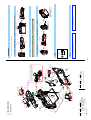
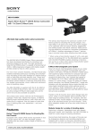
Photo: NEX-7/Black
4:,X¦õÌw«
²©ßÏɿĦõÌw«
9-834-618-35
NEX-7/7K_L2
Service Manual of Lens
No supplied lens
9-852-799-1[]
2
Les composants identifiés par
une marque 0 sont critiques
pour la sécurité.
Ne les remplacer que par une
pièce portant le numéro spécifié.
2012.04
2012.07
1.4
2012.02
1.3
1.2
2011.10
2012.01
1.0
Date
1.1
Ver.
Sony Corporation
INTERCHANGEABLE LENS DIGITAL CAMERA
Lens
No supplied lens
SEL1855 (E 18-55mm F3.5-5.6 OSS)
The components identified
by mark 0 or dotted line with
mark 0 are critical for safety.
Replace only with part number
specified.
Model
NEX-7
NEX-7K
LEVEL
US Model
Canadian Model
AEP Model
UK Model
E Model
Australian Model
Chinese Model
Korea Model
Japanese Model
Tourist Model
w NEX-7K is commodity that packed the Interchangeable Lens Digital Camera and Interchangeable Lenses.
Refer to each following service manual the Interchangeable Lens kit, when you repair.
w When replacing a part of lens (SEL1855), do not replace the part of silver model with the one for black model and vice versa.
[About the service of this model]
1-1.
1-1. PRECAUTION ON REPLACING THE SY-296 BOARD
1-2. PRECAUTION ON REPLACING THE CABINET FRONT
– JAPANESE –
– ENGLISH –
SERVICE NOTE (Check the following note before the service.)
Replace the previously issued
SERVICE MANUAL 9-834-618-34
with this Manual.
Revised-4
Ver. 1.4 2012.07
SERVICE MANUAL
NEX-7/7K
Revised-4
(A4 12-190)
Revised-3
(A3 12-056)
Revised-2
(A2 11-353)
Revised-1
(A1 11-323)
Official Release
History
• Correction of REPAIR PARTS LIST.
Page 2-9
• Correction of REPAIR PARTS LIST.
Page 2-4, 2-6, 2-7
• Correction of ACCESSORIES.
Page 2-12
• Correction of ACCESSORIES.
Page 2-12
• Correction of REPAIR PARTS LIST.
Page 2-8
• Addition of ASSEMBLY.
Page 3-2
—
Contents
Revision History
2012G08-1
© 2012.07
Published by Sony Techno Create Corporation
Yes
Yes
Yes
Yes
—
S.M. Rev.
issued
983461835 .pdf
NEX-7/7K_L2
K Abbreviation
AUS : Australian model
CND : Canadian model
CH : Chinese model
J:
Japanese model
JE :
Tourist Model
KR : Korea model
Lens
Destination
Model
NEX-7
F3.5
3.3 - 5.6
3.3 - 7.9
3.6 - 11
5.2 - 16
F5.6
3.3 - 3.6
3.3 - 4.9
3.3 - 6.9
3.3 - 9.8
NEX-7K
Used battery: Lithium-ion battery
Maximum voltage: DC 8.4 V
Nominal voltage: DC 7.2 V
Maximum charge voltage: DC 8.4 V
Maximum charge current: 1.02 A
Capacity: Typical 7.7 Wh (1 080 mAh)
Minimum 7.3 Wh (1 020 mAh)
Maximum dimensions:
Approx. 31.8 × 18.5 × 45 mm
(1 5/16 × 3/4 × 1 13/16 inches)
(W/H/D)
Mass: Approx. 57 g (2.1 oz)
Rechargeable battery pack
NP-FW50
Input rating: 100 V – 240 V AC,
50 Hz/60 Hz, 4.2 W
Output rating: 8.4 V DC, 0.28 A
Operating temperature range: 0°C to
40°C (32° to 104°F)
Storage temperature range: –20°C to
+60°C (–4°F to +140°F)
Maximum dimensions: Approx. 63 ×
95 × 32 mm (2 1/2 × 3 3/4 × 1 5/16
inches) (W/H/D)
Mass: Approx. 85 g (3 oz)
Battery charger BC-VW1
Flash range (feet):
ISO
F2.8
100
3.3 - 6.9
200
3.3 - 9.8
400
4.6 - 14
800
6.6 - 20
–2–
Flash guide number: GN 6 (in meters at
ISO 100)
Recycling time: Approx. 4 seconds
Flash coverage: Covering 18 mm lens
(focal length that the lens indicates)
Flash compensation: ±3.0 EV (1/3 EV
step)
Flash range (m):
ISO
F2.8
F3.5
F5.6
100
1 - 2.1
1 - 1.7
1 - 1.1
200
1-3
1 - 2.4
1 - 1.5
400
1.4 - 4.3 1.1 - 3.4 1 - 2.1
800
2 - 6.1
1.6 - 4.8 1 - 3
E 18-55mm F3.5-5.6 OSS
Ü7.5 cm
¢3.0£
TFTæ
Å¿Ä:921 600
¢640·3¢RGB£·
480£Å¿Ä
¦÷¥ÞÇ»§
Ü? ÜÏáÑ ï¼¢;
EL£
hر ¶1.3 cm
¢0.5£
ïÅ¿Ä:2 359 296Å¿Ä
¹úpÿ100%
p1.09¢50 mmèï¶zÁvz¹
Sµ1 mµ1Ì£
Ù ïÄ74«¶ØTÿ
23 mmzîTÿ21 mm¢¹
Sµ1 mµ1Ì£
1
¹SÐTµ4.0 mµ1 ´1.0 mµ¢Ã
¦Ó»£
¦Ñ G
ÝÞæµÂ¿« PRO Ãᦡz
SD§Å
¦GåÝç
Ü? MÜNøÑ¥§çÓ
èï³ß¿»
³ß¿»µÐÅc1/4000
30 µzÌçÒ¢1/3µÂ¿Ó£
Ñ忳áÐS1/160µ
¦³ß¿»§
«MÜ Ý´·ï±t
1 200ü«
«cEV0 EV20
¢ISO 100ìpz
F2.8èï¶;Ì£
ISOòS¢*Ы¦:£¦Äz
ISO100 16000
ÐZ4Y¶5.0EV
¢1/3µÂ¿Ó£
¦ÐZM§
ܯïÄåµÄUZMÜ
UZKScEV0 EV20
¢ISO 100ì
pzF2.8èï¶;Ì£
¦¦ÄÑ¥§µ§
³µÂÜ3?w¯ÄS|Ò;þ
ütï½¼µÄ;ó
¦ï½¼µÄ§
Ý´·ï±23.5 · 15.6 mm
¢APS-C± ¶£zCMOS Ý´·
ï±
ïhÉ:ÿ24 700 000hÉ
§Ýå®hÉ:ÿ24 300 000hÉ
¦qþæ§
§Ýå» ÓèﶦõÜô»ç§
Ýå
;èï¶EÚ¢ïÄèï¶
.
¦Ü§
[Flash]
US, CND, AEP, UK, E, KR, AUS, CH, JE, J
Exif Print: Compatible
PRINT Image Matching III:
Compatible
Dimensions (CIPA compliant):
Approx. 119.9 mm × 66.9 mm ×
42.6 mm (4 3/4 inches × 2 3/4
inches × 1 11/16 inches) (W/H/D)
Mass (CIPA compliant):
Approx. 350 g (12.3 oz)
(including battery and “Memory
Stick PRO Duo” media)
Approx. 291 g (10.3 oz)
(camera only)
Operating temperature: 0°C to 40°C
(32°F to 104°F)
File format:
Still image: JPEG (DCF Ver. 2.0,
Exif Ver. 2.3, MPF Baseline)
compliant, DPOF compatible
3D still images: MPO (MPF
Extended (Disparity Image))
compliant
Movie (AVCHD format):
AVCHD format Ver.2.0
compatible
Video: MPEG-4 AVC/H.264
Audio: Dolby Digital 2ch
Dolby Digital Stereo Creator
• Manufactured under license from
Dolby Laboratories.
Movie (MP4 format):
Video: MPEG-4 AVC/H.264
Audio: MPEG-4 AAC-LC 2ch
USB communication: Hi-Speed USB
(USB 2.0)
[Others]
Used battery pack: Rechargeable
battery pack NP-FW50
[Power]
USB: miniB
HDMI: HDMI type C minijack
US, CND, AEP, UK, E, KR, AUS, CH, J
Model information table
Type: Electronic viewfinder (Organic
Electro-Luminescence)
Screen size: 1.3 cm (0.5 type)
Total number of dots: 2 359 296 dots
Frame coverage: Approx. 100%
Magnification: 1.09 × with 50 mm lens
at infinity, –1 m–1 (diopter)
Eye point: Approx. 23 mm from the
eyepiece, 21 mm from the eyepiece
frame at –1 m–1
Dioptor adjustment: –4.0 m–1 to
+1.0 m–1 (diopter)
[Electronic viewfinder]
“Memory Stick PRO Duo” media,
SD card
[Recording media]
Type: Electronically-controlled,
vertical-traverse, focal-plane type
Speed range: 1/4000 second to 30
seconds, BULB (1/3 EV step)
Flash sync speed: 1/160 second
[Shutter]
Metering method: 1 200-segment
metering by the image sensor
Metering range: EV0 to EV20 (at ISO
100 equivalent, with F2.8 lens)
ISO sensitivity (Recommended
exposure index): Auto, ISO 100 to
16000
Exposure compensation: ±5.0 EV (1/3
EV step)
[Exposure control]
System: Contrast detection system
Sensitivity range: EV0 to EV20 (at ISO
100 equivalent, with F2.8 lens)
[Auto focus system]
System: Charge protection coating on
Optical Filter and ultrasonic
vibration mechanism
[Anti-dust]
Image sensor: 23.5 × 15.6 mm (APS-C
format) CMOS image sensor
Total pixel number of image sensor:
Approx. 24 700 000 pixels
Effective pixel number of camera:
Approx. 24 300 000 pixels
[Image sensor]
[Input/output terminals]
LCD panel: 7.5 cm (3.0 type) TFT
drive
Total number of dots: 921 600 (640 × 3
(RGB) × 480) dots
[System]
Camera type: Interchangeable lens
digital camera
Lens: E-mount lens
[LCD monitor]
Camera
SPECIFICATIONS
– ENGLISH –
ISO
100
200
400
800
F2.8
1 2.1
13
1.4 4.3
2 6.1
F3.5
1 1.7
1 2.4
1.1 3.4
1.6 4.8
¨ ÅÆïÌ6¢ISO100~m£
F?Ìÿ4µ
°ù¯18 mmèﶧ̢èï
¶¯Gw¯:m£
Ы4Y¶3EV
¢1/3µÂ¿Ó£
Ñ忳á«w§Xm(m)
¦Ñ忳á§
Exif Print0
PRINT Image Matching III0
GO
¢CIPAj£
ÿ119.9 mm·66.9 mm·
42.6 mm¢ï·ô^·æV£
.í
¢CIPAj£
ÿ350 g
¢Ì¿Âæz
ÝÞæµ
¿« PRO Ãᦡ£
ÿ291 g
¢.w£
^9S0Æ 40Æ
GåMÜ
ihGåMÜ
JPEG¢DCF Ver.2.0zExif Ver.2.3z
MPF Baseline£jzDPOF0
3DihGåMÜMPO¢MPF
Extended¢q.¹££j
hGåMÜ
¢AVCHDMÜ£
AVCHDF¨ Ver.2.0j
éþMPEG-4 AVC/H.264
;`Dolby Digital 2ch
ÅçÏô»çµÂ覫æ¤
»eL
wÅçÏåØåÄæ¶Twî
ªVt,nVa^oMb{
hGåMÜ
¢MP4MÜ£
éþMPEG-4 AVC/H.264
;`MPEG-4 AAC-LC 2ch
USBèôHi-Speed USB¢USB2.0£
¦fw§
Ì¿Âææ½ß´ßÒçÌ¿Â
æÍ¿«NP-FW50
¦?o§
USBz miniB
HDMIz HDMI» ÓCÛÇz ¦ÖZz §
t7
F5.6
1 1.1
1 1.5
1 2.1
13
;?æ½¢Ü ¦ï?
7G?yDC 8.4 V
¦?yDC 7.2V
0¬¶0 7.7 Wh¢1 080 mAh£
¨
¢7£
07.3 Wh
¢1 020 mAh£
7GGOÿ31.8·18.5·45 mm
¢ï·ô^·æV£
.íÿ57 g
æ½ß´ßÒçÌ¿Âæ
Í¿«/1'8
¨ÖAC100 V – 240 Vz
50 Hz/60 Hzz4.2 W
¨ZDC 8.4 Vz0.28 A
^9S0Æ 40Æ
-9Sµ20Æ´60Æ
7GGOÿ63·95·32 mm
¢ï
·ô^·æV£
.íÿ85 g
Ì¿Âæ½ß´ß
#$78
– JAPANESE –
Store chemicals sealed in a specific place to prevent from exposure
to high temperature or direct sunlight.
Avoid dividing chemicals into excessive numbers of small containers
to reduce natural evaporation.
Keep containers sealed to avoid natural evaporation when chemicals
are not in use.
Avoid using chemicals as much as possible. When using chemicals,
divide only required amount to a small plate from the container and
use up it.
•
•
Set the soldering iron tip temperature to 350°C approximately.
If cannot control temperature, solder/unsolder at high temperature
for a short time.
Caution: The printed pattern (copper foil) may peel away if the
heated tip is applied for too long, so be careful!
Unleaded solder is more viscous (sticky, less prone to
flow) than ordinary solder so use caution not to let solder
bridges occur such as on IC pins, etc.
Be sure to control soldering iron tips used for unleaded solder and
those for leaded solder so they are managed separately. Mixing
unleaded solder and leaded solder will cause detachment phenomenon.
: LEAD FREE MARK
Be careful to the following points to solder or unsolder.
This unit uses unleaded solder.
Boards requiring use of unleaded solder are printed with the lead free
mark (LF) indicating the solder contains no lead.
(Caution: Some printed circuit boards may not come printed with the
lead free mark due to their particular size.)
UNLEADED SOLDER
After correcting the original service problem, perform the following
safety checks before releasing the set to the customer.
1. Check the area of your repair for unsoldered or poorly-soldered
connections. Check the entire board surface for solder splashes and
bridges.
2. Check the interboard wiring to ensure that no wires are “pinched”
or contact high-wattage resistors.
3. Look for unauthorized replacement parts, particularly transistors,
that were installed during a previous repair. Point them out to the
customer and recommend their replacement.
4. Look for parts which, through functioning, show obvious signs of
deterioration. Point them out to the customer and recommend their
replacement.
5. Check the B+ voltage to see it is at the values specified.
6. Flexible Circuit Board Repairing
• Keep the temperature of the soldering iron around 350°C during
repairing.
• Do not touch the soldering iron on the same conductor of the circuit
board (within 3 times).
• Be careful not to apply force on the conductor when soldering or
unsoldering.
NEX-7/7K_L2
ATTENTION AU COMPOSANT AYANT RAPPORT
À LA SÉCURITÉ!
LES COMPOSANTS IDENTIFIÉS PAR UNE MARQUE 0 SUR LES
DIAGRAMMES SCHÉMATIQUES ET LA LISTE DES PIÈCES SONT
CRITIQUES POUR LA SÉCURITÉ DE FONCTIONNEMENT. NE REMPLACER CES COMPOSANTS QUE PAR DES PIÈCES SONY DONT
LES NUMÉROS SONT DONNÉS DANS CE MANUEL OU DANS LES
SUPPLÉMENTS PUBLIÉS PAR SONY.
•
Use a piece of cleaning paper or cleaning cloth for cleaning plastic
parts. Avoid using chemicals.
Even if you have to use chemicals to clean heavy dirt, don’t use paint
thinner, ketone, nor alcohol.
Insert the specific screws vertically to the part when installing a
plastic part.
Be careful not to tighten screws too much.
SAFETY CHECK-OUT
COMPONENTS IDENTIFIED BY MARK 0 OR DOTTED LINE WITH
MARK 0 ON THE SCHEMATIC DIAGRAMS AND IN THE PARTS LIST
ARE CRITICAL TO SAFE OPERATION. REPLACE THESE COMPONENTS WITH SONY PARTS WHOSE PART NUMBERS APPEAR AS
SHOWN IN THIS MANUAL OR IN SUPPLEMENTS PUBLISHED BY
SONY.
SAFETY-RELATED COMPONENT WARNING!!
Caution
Danger of explosion if battery is incorrectly replaced.
Replace only with the same or equivalent type.
Dispose of used batteries according to the instructions.
•
•
•
•
•
–3–
-Ôt|ô9tslhÚùÔ«wphsMÔ
ttµ`o-`oXi^M{
üZ¢ËïÅå¿Ós£b:xA7vty|0+
t×µàCwMpXi^M{
^Àt;`sMÌx|c©ß¿Ós`o×µàC
wMpXi^M{
¼;bs:ÃsX`|;bÔùx;
biZ0+Z`o!Z|t^sMOt`oX
i^M{
«ÄòSXi^M{
±ÏµwqVt«AbxttmMox|©ßÏ
É¿Ä|³ß³|æ¼srtåÕçÀ¹p«Äò
¯Ô`oMb{\w«{VS|{Ì{sw
«ÄòcSXi^M{
¦æ¼w];
·¿Äwæ¼xÉéQ1?ysr¶ÍwQËlh
wqsloMb{Hlo¦õæ¼x|;^oMh
wqaQwæ¼;`oXi^M{tsÏ$|
漯t0¹p¦^oM¶ÍOAsæ¼xc¦
ww];Xi^M{
æ¼wÇZ¢w¾V`xqrSt
¶Í|½áÒÂÓsrwP;`h|
ÓæïÄ,XTÔT`oÇZhæ¼UKb{h
ºæ¢x¾V`«åïÍtloCäæ¼ôy
æ¼tÙ`sMO^oMbwp|\x
cqrSt`oXi^M{
±Ïµx¶:U
±Ïµwht`hÉ´|æ¼|¢UqrS
tsloMT|h±Ïµ`hxtw*%¼=^d
o`lhq\UsMTsr:U`|¶QU¬-^
oM\q¬Ý`oXi^M{
½¿Ó漦õÌw«
~ `hæ¼x6;`sMpXi^M{
~ »ï»ç¯ïÃï±wÚ ÆµxätMh¦õÌ
x«`oXi^M{
Ñ詳ÒçÓæïÄ,Xw{MtmMo
~ \o9SÿÆt`oæloXi^M{
~ °Í»ït?S\oposMpXi^M{
¢sº£
~ Í»ïtUCsMO«`oXi^M{
– JAPANESE –
~
~
Zßtx ¼;dc|Zß´ZßÍ;`oXi
^M{
cU{rXo ¼;bÔùx|³ï
Æ|Äï|¤Âçx;`sMpXi^M{
¤æ¼wÇZtx¦^hva;`|æ¼t0
`o(ÚtÇZoXi^M{
h|vaÇZÌx|ÁgsCQsMpXi
^M{
;t;^oM%·%wæ¼x|<Gw:t«`o
{loXi^M{
%·%æ¼w{MtmMo
~
~
R>\ow\o9SxÿÆt`oXi^M{
9SÐ
UÁgsÔùx|ô9yÌp^ÀæloXi
^M{
«R > \ o Õ X p o b W q| , X w Í »
ï¢)£UxUo`O\qUKbwp|«
`oXi^M{h|HRwR>êQU§
Mh|*$z srUR>Òæ¿´`sMOt«
`oXi^M{
R>\ow\ox|cÁR>;qR>;tüZ
og`oXi^M{
ÁR>qR>UObq#mqÅUC\`o`
Mb{
ÁR>x|<Gw:t«`o;`oXi^M{
è¿ÅÑæÚ«
;txÁR>U;^oMb{
ÁR>;`oM,Xtx|Á
¢-FBE'SFF£¯b
è¿ÅÑæÚ«UÓæïÄ^oMb{
¢«,X± ¶tlox|ÁR>;`oMo
è¿ÅÑæÚ«UÓæïÄ^oMsMwUK
b£
ÁR>tmMo
±Ïµ|:UÌtxÍw\qt]«Xi^M{
Caution
?w¦õx|Y`XæsMq¾bªUKb{
?¦õbÔùtxcaÊw?¢xs¼q
¦õ`oXi^M{
;A?x|{¦ÔtHlorü`oXi^M{
~
~
~
~
qO;^oM ¼w¤tx4CQwôM ¼K
b{
fÆ;t{MàC^do`Oq| ¥HÁ
è¹)Qh|¿owÁ,Mtsb{
¤ ¼x|<Gw:t«`o{loXi^M{
Be careful to the following points for plastic parts used in this unit.
Some chemicals used for servicing are highly volatile.
Their evaporation caused by improper management affects your health
and environment, and wastes resources.
Manage the chemicals carefully as follows.
¼w{MtmMo
¤
– ENGLISH –
EXTERIOR PARTS
CHEMICALS
1-1E
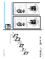
«²©ßÏÉ¿Äw¦õæO²tzq
T
to¦õ²wGO`oXi^M{
Ý´ß "TTZz*.ÐTë¿³ß "#$
`oXi^M{
`h*.ÐT뿳ßwGO¢A£`oXi^M{
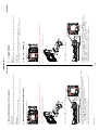
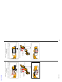
(1) Remove the Imager Block Assy and the IM Adjust Washers (A, B, C).
(2) Measure the dimensions (A) of the removed IM Adjust Washers.
NEX-7/7K_L2
(3) Measure the distance (B) between the surface of the screw hole where the IM Adjust Washers were set and the surface of the E-Mount.
(4) Likewise, measure the dimensions (B’) of each location where IM Adjust Washers of new Cabinet Front are installed.
(5) Calculate the dimension of (A’) of new IM Adjust Washer by using the formula below, and select the washers.
Dimension (A+B) before replacement – Dimension (B’) of new Cabinet Front
= Dimension (A’) of IM Adjust Washer after replacement
(6) Assemble the imager, using the selected IM Adjust Washers.
(7) After assembling is completed, perform the test shooting and confirm that no blur is observed in the peripheral area of shot.
B
A
Note: Measure the dimensions before replacement of the Cabinet Front according to procedures (1) to (3).
A+B
<wqxUtfgæloXi^M{
²©ßÏɿĦõÌw«
1-2. PRECAUTION ON REPLACING THE CABINET FRONT
*.ÐT뿳ßUÇMoMhϵ@zØT&.PVOUzØpwGO¢B£`oXi^M{
ý¼w²©ßÏÉ¿Äw¤*.ÐT뿳ßÇZætmMo7tGO¢B£`oXi^M{
<wÜýht;b*.ÐT뿳ßwGO¢A£Z`z뿳ßw¬æloXi^M{
¦õ²wGO¢AB£µý²©ßÏÉ¿ÄwGO¢B£¦õw*.ÐT뿳ßGO¢A£
¬`h*.ÐT뿳ß;`o Ý´ßÊÇZoXi^M{
ÊqìRz¼`qæM*%ØswÆéùUÁM\q¬Ý`oXi^M{
B
A
Perform the following procedures for each of the three washers.
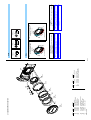
64#³æç/P
·¿ÄxzFts{w*%¢64#4FSJBM/P£{VizZY^oMb{
ý¼w4.;,Xtxz\w*%U{VoMsMwp|,X¦õt*%ÖbAUKb{
The set is shipped with a unique ID (USB Serial No.) written in it.
This ID has not been written in a new board for service, and therefore it must be entered after the board replacement.
4.;,Xq¦õbÌz4.;,Xt{ToM²Zûxiwq§loMÔùUKb{
USB Serial No.
²Zû
4:,X¦õÌw«
When you replace to the repairing board, the written destination data of repairing board also might be changed to original setting.
– ENGLISH –
Destination Data
1-1. PRECAUTION ON REPLACING THE SY-296 BOARD
1. SERVICE NOTE
A+B
– JAPANESE –
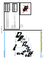
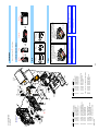
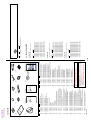
IDENTIFYING PARTS
NEX-7/7K_L2
Link
DISCHARGING OF THE CHARGING CAPACITOR
ACCESSORIES
ASSEMBLY
2 Cabinet (Rear) Block
6 SY-296 Board
8 JC Base Section
• ST-265 Flexible Board
3 LCD Block
• LC-098 Flexible Board
• RK-002 Flexible Board
qa Imager Unit
qs MB Charge Unit
qd Shutter Unit
4 VF Block
qf Cabinet (Front) Section
9 RL Block
• RL-116 Flexible Board
7 Shoe Block
5 BT Lid Block
q; BT Block
• CN-474 Board
• BT-074 Flexible Board
• FP-1451 Flexible Board
1 Top Section
Follow the disassembly in the numerical order given.
2-1
• Abbreviation
AUS : Australian model
CH : Chinese model
CND : Canadian model
J
: Japanese model
JE
: Tourist model
KR : Korea model
S&M
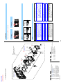
Color Indication of Appearance Parts
Example:
(SILVER) : Cabinet’s Color
(Silver) : Parts Color
Front View
Left View
Bottom View
Top View
Right View
Back View
÷æ¼í¯Ô
«
4*-7&3
·¿Äwí¯b{
4JMWFS
æ¼wí¯b{
0¹wæ¼|hx0¹Çw:¢p
hæ¼x|¶Q¡Ëbht|
OAsæ¼pb{
Hlo¦õÌx|c¦wæ¼;
`oXi^M{
$Øjøp漦bqVx,XÊ
¢xÒé¿«do¦`oXi^M{
w
•
Les composants identifiés par une marque
0 sont critiques pour la sécurité.
Ne les remplacer que par une pièce portant
le numéro spécifié.
The components identified by mark 0 or
dotted line with mark 0 are critical for safety.
Replace only with part number specified.
When indicating parts by reference number,
please include the board name.
View Position
²;Íw«³
w 999xªj=æ¼wh·¿ÄtÇMoMæ¼qsÔùUKb{
w ¹wæ¼x×O`oSd{
w \\tGL^oMæ¼x 4.;æ¼pKh sÏ$t|·¿ÄtÇMoMæ¼q
sÔùUKb{
(JAPANESE)
NOTE:
• -XX, -X mean standardized parts, so they may have some differences from the original one.
• Items marked “ ” are not stocked since they are seldom required for routine service. Some delay
should be anticipated when ordering these items.
• The mechanical parts with no reference number in the exploded views are not supplied.
• Due to standardization, replacements in the parts list may be different from the parts specified
in the diagrams or the components used on the set.
(ENGLISH)
2. REPAIR PARTS LIST
NEX-7/7K_L2
Wrap insulating tape.
1 kΩ/1 W
To preparing the short jig, a small clip is attached to each end of
a resistor of 1 k: /1 W (1-215-869-11).
Wrap insulating tape fully around the leads of the resistor to
prevent electrical shock.
Preparing the Short Jig
The charging capacitor is charged up to the maximum 330 V
potential.
There is a danger of electric shock by this high voltage when the
capacitor is handled by hand. The electric shock is caused by the
charged voltage which is kept without discharging when the main
power of the unit is simply turned off. Therefore, the remaining
voltage must be discharged as described below.
DISCHARGING OF THE CHARGING
CAPACITOR (C901)
• Do not apply excessive load to the gilded flexible board.
• When installing a connector, don’t press down at wire of connector.
It is possible that a wire is snapped.
• When remove a connector, don’t pull at wire of connector. It is
possible that a wire is snapped.
• Make sure that the flat cable and flexible board are not cracked
of bent at the terminal.
Do not insert the cable insufficiently nor crookedly.
NOTE FOR REPAIR
2-2
C901
ST-265 Flexible Board
ST-265 Flexible Board
R:1 k :/1 W
(Part code: 1-215-869-11)
¯ïÃï±wL?
Ñ忳áâÇ¿Äw?o¯ïÃï±
wz ³ãÄÏépÿø÷µ
b{
55éøÇ ÚT6 ñê 6;Òá
°ðÒáÊÛп•
ÔT6 • Ç&@"2]æwÞá¿
•'ý½ éâHçÒáÊÛпÕ
C901
Ø<9oJâÎÊ
1 kΩ/1 W
³ãÄÏéxL
8Å¢£
w«æ¿Ó`o^R`b{
Å+xÂÓpì¶tôM?>³ã¿«!Zs
MOt`oXi^M{
³ãÄÏéwj
µÄéØ;F?¯ïÃï±x7G7w?ypF?^
oMb{
\wô?ypF?^h¯ïÃï±tîhÔù|
?>³ã¿«!Zb{\wô?ytxot·¿Äw
?o~lhiZpxL?^c|y`oMb{\
wh|<GwMOpy?yL?`oXi^M{
µÄéØ;F?¯ïÃï±
¢$£
wL?
w ÚÝ¿©^oMÑ詳Òç,Xtx|§MÛrTZ
sMpXi^M{
w ¢Pæ¢ÃI£!^QsU¯É«»)`q|¢Pæ
¢ÃI£U
¢bªUKbwp|0t¢Pæ¢ÃI£
txÛrTZsMpXi^M{
w ¯É«»bÌt|¢Pæ¢ÃI£Ëlo¾lÁq
¢bªUKbwp|0t¢Pæ¢ÃI£Ëlo
¾lÁsMpXi^M{
w Ñå¿ÄÒçS|Ñ詳Òç,Xwz Øt=Z|
sUsM\q¬Ýb{
h|¯É«»wx|)`Æü)`ts
sMOt«b{
.gÌw«
– JAPANESE –
ST-265 Flexible Board
ST-265 Flexible Board
R:1 k :/1 W
(Part code: 1-215-869-11)
Discharging the Capacitor
Short-circuit between two points with
the short jig about 10 seconds.
Note: High-voltage cautions
Cut and remove the part of gilt
which comes off at the point.
(Be careful or some
pieces of gilt may be left inside)
– ENGLISH –
Part No.
4-300-399-01
4-300-387-01
X-2582-867-1
4-300-405-01
4-300-400-01
NEX-7/7K_L2
1
2
3
4
5
Ref. No.
4-1
2-2
4-2
2-1
#242
#242
#242
#242
Adjust the position.
Adjust the position.
#242
BUTTON (SK) (600)
SHEET (SK BUTTON) (600)
CABINET (REAR) ASSY (600)
SHEET (SK CAP) (600)
CAP (SK BUTTON) (600)
Description
LCD Section
(See page 2-5)
17
2-1-1. REAR SECTION
2-1. EXPLODED VIEWS
4-178-124-81
#242
4
2
4-292-101-01
4-400-730-01
Part No.
1
6
7
Ref. No.
3
#242
SPECIAL (M1.4 (D2.75))
BUTTON, REC (Note)
COVER (600), SHOE
Description
5
Adjust the position.
6 (Note)
#242
43
Be careful not to make scars on the unit with a
screwdriver when removing the Top Section.
(See page 2-4)
2 Top Section
2-3
#242
2-1
#242
Top View
1.4
#242
#242
4-2
Bottom View
Refer to "Assembly-9:Installation Cautions of the Rec
Button." when you assemble.
Note
3.5
#242: M1.4 X 3.5
(Black)
4-178-124-81
#242
Right View
Screw
4-1
Note:
Back View
µÄéØ;F?¯ïÃï±wL?
#242
Note:
2-2
Bottom View
Remove Cabinet (Rear) Assy
while turning it in the
direction indicated by arrows.
#242
ÊqÌxlAssembly-9:Installation Cautions of the Rec Button.z°`oXi^M{
Open LCD at the angle
shown below.
Right View
4 Open the HDMI Lid (4-1) : #242 X 1 : Open the BT Lid (4-2) : #242 X 3
DISCHARGING OF THE CHARGING CAPACITOR
3
Right View
2 #242 X 1 : Popup the Strobo (2-1) : #242 X 3 : Open the BT Lid (2-2) : #242 X 2
1. Remove to numerical order (1 to 4) in the left figure.
DISASSEMBLY
4-300-367-01
X-2582-857-1
4-300-370-01
4-300-369-01
1-489-953-11
61
62
63
64
65
NEX-7/7K_L2
4-300-405-01
4-300-400-01
4-300-364-01
4-300-368-01
4-300-383-01
56
57
58
59
60
Part No.
4-300-360-01
4-300-359-01
X-2583-801-1
4-186-500-01
4-300-372-01
51
52
53
54
55
Ref. No.
53
52
55
51
61
78
60
59
CAP (PW RING) (600)
GUIDE (RL) ASSY (600)
BUTTON (RL) (600)
CAP (RL) (600)
ST UNIT (75600)
SHEET (SK CAP) (600)
CAP (SK BUTTON) (600)
SHEET (FN) (600), ADHESIVE
KNOB (PW) (600)
SHEET (PW KNOB) (600), ADHESIVE
SLIDER (PW) (600)
PLATE (PW) (600), CLICK
BASE (GUIDE RL) (600) ASSY
SHEET, RL BUTTON ADHESIVE
BUTTON (FN) (600)
Description
ns
56
57
58
62
77
63
54
64
Adjust the position.
ns: not supplied
2-1-2. TOP SECTION
The changed portions from
Ver. 1.2 are shown in blue.
Ver. 1.3 2012.04
#76
#242
#242
‘
X-2582-860-1
4-300-356-01
4-300-357-01
4-300-362-01
4-186-543-01
4-300-410-01
4-410-556-01
4-300-408-01
1-489-939-11
1-820-649-11
1-820-649-21
4-186-501-01
4-186-497-01
2-666-551-11
4-178-124-81
71
72
73
74
75
76
77
78
#76
#242
Part No.
74
66
67
68
69
70
Ref. No.
#76
73
72
71
Gray
White
76
66
#76
75
Brown
Adjust the position.
ns
69
68
SCREW, TAPPING, P2
SPECIAL (M1.4 (D2.75))
HOUSING, CONNECTOR 2P (Yellow)
SHEET, RL GUIDE ADHESIVE
SPRING, RL
INSULTING SHEET (CAB TOP) (600)
SHEET (DIAL) (600)
PLATE (DIAL) (600)
SWITCH BLOCK, CONTROL (TD75600)
HOUSING, CONNECTOR 2P (Red)
DIAL ASSY (600)
CABINET (UPPER) (600)
ORNAMENT (VF) (600)
SHEET (VF ORNAMENT) (600)
PLATE, LOGO
Description
70
67
(Note)
65
2-4
DISASSEMBLY
Note:
3.5
#242: M1.4 X 3.5
(Black)
4-178-124-81
1.4
Refer to "Assembly-8:Installation Cautions of the ST Unit
(75600)." when you assemble.
Note
4.0
1.7
#76: M1.7 X 4.0 (Tapping)
(Silver)
2-666-551-11
Screw
Note:
1. The meaning of the sign in left figure is as follows. Be careful when it removes.
Ö: Solder
ÊqÌxlAssembly-8:Installation Cautions of the ST Unit
(75600).z °`oXi^M{
4-300-377-01
4-300-397-01
A-1847-880-A
X-2582-868-1
4-300-404-01
111
112
113
114
115
NEX-7/7K_L2
4-293-878-01
A-1847-878-A
1-489-775-41
4-297-178-01
4-297-177-01
106
107
108
109
110
#196
ns
X-2582-862-1
4-293-878-01
4-300-406-01
4-300-373-01
X-2582-861-1
Part No.
102
#196
101
102
103
104
105
Ref. No.
101
#242
#196
1 104
103
#239
SHEET (MAIN FRAME) (600)
LIGHT (LC) (600), GUIDE,
LC-098 FLEXIBLE BOARD, COMPLETE
HINGE ASSY (600) (Note)
RETAINER (LC) (600), FLEXIBLE
EYELET TRIANGLE STOPPER
RK-002 FLEXIBLE BOARD, COMPLETE
SWITCH BLOCK, CONTROL (600)
COVER (R) (600), HINGE
COVER (L) (600), HINGE
110
#242
HOOK (L) ASSY (600), STRAP
EYELET TRIANGLE STOPPER
CAP (LC) (600), FLEXIBLE
FRAME (MAIN) (600)
HOOK (G) ASSY (600), STRAP
Description
Main Board Section
(See page 2-6)
ns: not supplied
2-1-3. LCD SECTION
111
#196
117
107
106
4-300-376-01
4-416-468-01
4-419-209-01
4-300-402-01
4-300-403-01
1-471-549-11
4-300-401-01
4-300-388-01
#196
#239
#242
4-178-124-01
4-287-435-11
4-178-124-81
LCD901 A-1857-130-A
121
122
123
116
117
* 118
119
120
112
120
113
121
119
118
(Note 1)
114
SPECIAL (M1.4 (D2.75))
SCREW (M1.4 EUROPE) TYPE
SPECIAL (M1.4 (D2.75))
LCD BLOCK ASSY (SERVICE) (Note)
SHEET (LC) (600), INTERCEPTION
SHEET (LC FLEXIBLE) (600)
TAPE (SW) (600)
CLAW (LC), LOCK
HOLDER (LC) (600), LOCK
MAGNET (ND7.9X2.9X1.2)
CABINET (LC REAR) (600)
PLATE (LC REAR) (600)
Description
#196
(Note 2)
108
123
122
#196
115
Part No.
(Note 3)
116
109
Ref. No.
ns
105
LCD901
(Note 1)
#196
2-5
#242
1.4
#242
1.4
#239: M1.4 X 1.4
(Red)
4-287-435-11
Left View
1.4
Hinge Assy (600)
1.4
Note 3: Refer to "Assembly-7:Installation Cautions of the Lock Claw
(LC)." when you assemble.
Back View
#196
Note 3: ÊqÌxlAssembly-7:Installation Cautions of the Lock Claw
(LC).z °`oXi^M{
Note 2: ÊqÌxlAssembly-6:Installation Cautions of the Flexible
Retainer (LC) (600).z°`oXi^M{
Hinge Assy (600)
Note 1: LCD Flexible Board rgbqVxz
Hinge Assy (600) p LCD Flexible Board
mZsMOt«`oXi^M{
LCD Flexible Board
3.5
#242: M1.4 X 3.5
(Black)
4-178-124-81
#196
Bottom View
Note 2: Refer to "Assembly-6:Installation Cautions of the Flexible
Retainer (LC) (600)." when you assemble.
LCD Flexible Board
Note 1: When treating the LCD Flexible Board,
handle it with caution not to make scars
on the LCD Flexible Board with the
Hinge Assy (600).
Note
2.0
#196: M1.4 X 2.0
(Black)
4-178-124-01
Screw
Right View
#196
1 #196X 1 : #242 X 2 : #196 X 4
1. Remove to numerical order (1) in the left figure.
DISASSEMBLY
4-410-824-01
4-300-398-01
4-300-380-01
4-300-365-01
156
157
158
159
NEX-7/7K_L2
4-186-476-01
4-300-394-01
4-300-396-01
4-300-395-01
X-2582-866-1
Part No.
161
5 160
#242
LABEL (MS) (600)
PLATE (SP) (600), GROUND
PLATE (SY) (600), RADIATION
INSULATING SHEET (SY) (600)
SHAFT, BT LID
BASE (BT LID) (600)
LIGHT (MS) (600), GUIDE,
SPRING (BT LID OPEN) (600)
LID ASSY (600), BT
Description
Over All Section
(See page 2-7)
151
152
153
154
155
Ref. No.
1 162
(Size: 15mm X 5mm)
163
LCD902
2-1-4. MAIN BOARD SECTION
Ver. 1.3 2012.04
6
-29
SY
0+Z M1.4X2 NEW TORASUTA
SPECIAL (M1.4 (D2.75))
3-208-537-21
4-178-124-81
#177
#242
SY-296 BOARD, COMPLETE (SERVICE)
FRAME (VF) ASSY (600)
VF ASSY
SHEET (930), PROTECTION
GASKET (SH)
Description
ECX331AA-1
LOUDSPEAKER (1.0CM)
A-1853-412-A
X-2582-865-1
X-2582-570-2
CAUTION
4-281-580-01
#177
164
SP901
2 157
154
#242
153
‘ 156
3 152
LCD902 8-753-369-90
SP901 1-858-343-31
160
161
162
163
164
Part No.
4 158
Ref. No.
#177
159
155
151
2-6
1.4
CAUTION
3.5
#242: M1.4 X 3.5
(Black)
4-178-124-81
1.4
Back View
3 #242 X 1
4)&&5
1305&$5*0/xz/0/807&/5
~lo;b\q{
«
For the part of 163 : SHEET (930), PROTECTION, cut NON WOVEN
(T0.25) (3-076-631-01) into the desired length and use it.
Note
2.5
#177: M1.4 X 2.5
(Red)
3-208-537-21
Screw
#242
Back View
1 #242 X 1
#242
1. Remove to numerical order (1 to 5) in the left figure.
2. The meaning of the sign in left figure is as follows. Be careful when it removes.
Ö: Solder
DISASSEMBLY
#177
Back View
4 #177 X 4
#196
#242
4-300-355-01
4-300-361-01
4-300-381-01
4-292-160-11
4-300-378-01
A-1847-877-A
1-884-154-21
A-1847-234-A
X-2582-859-1
1-884-156-11
201
202
203
204
* 205
206
207
208
209
210
211
212
213
214
215
NEX-7/7K_L2
Part No.
X-2582-858-1
4-415-851-01
4-300-375-01
4-300-374-01
4-413-025-01
Ref. No.
#76
7 209
210
RL-116 FLEXIBLE BOARD, COMPLETE
BT-074 FLEXIBLE BOARD
CN-474 BOARD, COMPLETE
FRAME (BT) ASSY (600)
FP-1451 FLEXIBLE BOARD
WINDOW (AF) (600)
SHEET (MIC HOLE) (600)
SHEET (VF) (600), RADIATION
SCREW, TRIPOD
PLATE (600), MICROPHONE HOLDER
(See page 2-8)
2 JC Base Section
#177
6 MIC901
4 206
204
#242
208
207
207
202
1 CN901
203
GRIP (FRONT) ASSY (600)
SHEET (SHOE FRAME) (600)
BASE (SHOE) (600)
FRAME (SHOE) (600)
TAPE (F CAB)
Description
Imager Block Section
(See page 2-9)
205
8 201
#242
Be careful not to
drop a washer.
2-1-5. OVER ALL SECTION
The changed portions from
Ver. 1.2 are shown in blue.
Ver. 1.3 2012.04
4-281-580-01
4-300-371-01
1-880-964-11
1-880-963-11
1-780-858-11
1-822-402-21
1-542-905-11
2-666-551-11
3-208-537-21
4-178-124-01
4-178-124-81
BT901
CN901
MIC901
#76
#177
#196
#242
Part No.
218
216
217
218
219
Ref. No.
219
216
BT901
216
215
SCREW, TAPPING, P2
0+Z M1.4X2 NEW TORASUTA
SPECIAL (M1.4 (D2.75))
SPECIAL (M1.4 (D2.75))
TERMINAL BOARD BATTERY
SHOE CONNECTOR
MICROPHONE UNIT
GASKET (SH)
BASE (RL) (600)
IS-076 FLEXIBLE BOARD
IS-075 FLEXIBLE BOARD
Description
#242
217
#177
#242
3 211
212 ‘
213
5 214
#76
2-7
4.0
1.7
#76: M1.7 X 4.0 (Tapping)
(Silver)
2-666-551-11
Screw
Back View
#177
6 #177 X 2
#242
Back View
2.5
#177: M1.4 X 2.5
(Red)
3-208-537-21
1.4
#242
2.0
#196: M1.4 X 2.0
(Black)
4-178-124-01
1.4
#242
Bottom View
7 #242 X 1
2
3.5
#242: M1.4 X 3.5
(Black)
4-178-124-81
2 #242 X 1 : Bring down the ST-265 Flexible Board (2) : #242 X 1
1 #242 X 1: #196 X 1
1. Remove to numerical order (1 to8) in the left figure.
2. The meaning of the sign in left figure is as follows. Be careful when it removes.
Ö: Solder
DISASSEMBLY
1.4
#242
8 #242 X 1
Top View
Back View
5 #76 X 1
#76
NEX-7/7K_L2
A-1847-879-A
4-300-389-01
4-283-251-01
4-300-379-01
X-2582-863-1
256
257
258
259
260
Part No.
4-300-392-01
4-300-393-01
4-300-390-01
4-300-391-01
4-300-386-01
259
(Note 2)
261
253
258
ST-265 FLEXIBLE BOARD, COMPLETE
SHEET (MAIN CONVERTER) (600)
LENS CUSHION (910), BOTTOM
PLATE (CN) (600), RADIATION
BASE (JK) ASSY (600)
BH101
(Note 1)
‘
252
260
BT101
(Note 1)
ARM (ST DETECTION) (600)
SPRING (ST DETECTION) (600)
BASE (ST DETECTION) (600)
COVER (ST DETECTION) (600)
INSULATING SHEET (ST) (600) (Note 3)
Description
(Note 3)
255
251
252
253
254
255
Ref. No.
ns: not supplied
2-1-6. JC BASE SECTION
The changed portions from
Ver. 1.0 are shown in blue.
Ver. 1.1 2012.01
257
256
4-417-217-01
1-853-022-21
1-756-134-15
1-118-063-11
BH101
BT101
C901
Part No.
HOLDER, BATTERY (Note 1)
BATTERY, LITHIUM (SECONDARY) (Note 1)
CAP, ALUMINIUM ELECT 78uF 330V
TAPE (ST FLEX) (600), SHIELD (Note 2)
Description
: BT101 (LITHIUM SECONDARY BATTERY)
Board on the mount position.
(See page 6-32 of Level 3)
C901
ns
261
Ref. No.
254
251
2-8
DISASSEMBLY
CAUTION
Note 3: Refer to “Assembly-11: Installation Cautions of the Insulating Sheet (ST) (600).” when you assemble.
Note 2: Refer to “Assembly-10: Installation Cautions of the Shield
Tape (ST Flex) (600).” when you assemble.
Note 1: Replace the battery holder (BH101) together when
replacing the lithium storage battery (BT101) on the ST-265
Flexible board. (The battery holder removed once cannot
be usedagain.)
When mounting these parts, mount new battery holder first
and attach new lithium storage battery next.
?w¦õxzY`XæsMq¾bªU
Kb{?¦õbÔùtxcaÊw
?¢xs¼q¦õ`oXi^M{;A?xz
{¦ÔtHlorü`oXi^M{
«
Danger of explosion if battery is incorrectly replaced.
Replace only with the same or equivalent type.
Dispose of used batteries according to the instructions.
Note
Note 3: ÊqÌx lAssembly-11: Installation Cautions of the Insulating Sheet (ST) (600).z °`oXi^M{
Note 2: ÊqÌx lAssembly-10: Installation Cautions of the Shield
Tape (ST Flex) (600).z °`oXi^M{
Note 1: ST-265Ñ詳Òç,Xwæ½¢Ü? (BT101) ¦õ
bÔùx Ì¿Âæ×ç¼ (BH101) Ìtý¼t¦õ`
oXi^M{
(°S;`hÌ¿Âæ×ç¼x6;pVd{)
æ¼ÇZwMxztÌ¿Âæ×ç¼ÇZoT
æ½¢Ü?÷£`oXi^M{
1. The meaning of the sign in left figure is as follows. Be careful when it removes.
Ö: Solder
NEX-7/7K_L2
Selection Parts
Selection Parts
Selection Parts
4-292-165-01
4-300-303-01
* 306
* 307
* 308
309
310
Part No.
4-281-196-01
4-277-282-11
1-487-619-21
A-1817-096-B
4-288-878-01
301
302
303
304
305
Ref. No.
301
305
IM WASHER (A), ADJUST (Note 2, 3)
IM WASHER (B), ADJUST (Note 2, 3)
IM WASHER (C), ADJUST (Note 2, 3)
SHEET, IMAGER ELECTRIC HEAT
PLATE (IM) (600), RADIATION
#197
(Note 4)
302
(Note 4)
SHEET, MASK SHEET ADHESIVE (Note 4)
MB SHEET (754), MASK (Note 4)
SHUTTER UNIT (H094)
MB CHARGE UNIT (755)
SHEET, CUSHION (SH)
Description
Cabinet (Front) Section
(See page 2-11)
2-1-7. IMAGER BLOCK SECTION
The changed portions from
Ver. 1.3 are shown in blue.
Ver. 1.4 2012.07
3-208-537-21
4-185-990-01
4-287-436-01
#177
#197
#238
Part No.
A-1857-129-A
#238
(Note 1)
1 310
(FRONT) BLOCK ASSY (SERVICE)
(including CP6001 (CMOS imager) and IS-095 complete
board) (Note 5)
0+Z M1.4X2 NEW TORASUTA
MB SCREW, CHARGE UNIT FIXED
SCREW (M1.7) (Note 1)
Description
(Note 2, 3)
308
(Note 2, 3)
307
#177
309
(See page 2-10)
2 Imager Unit Section
(Note 2, 3)
306
4 304
311
Ref. No.
3 303
(including CP6001 (CMOS imager)
and IS-095 complete board)
(Note 5)
311
2-9
1.4
4.5
1.6
#197: M1.6 X 4.5 (Tapping)
(Silver)
4-185-990-01
Back View
Note 3: ÊqÌxlAssembly-2: IM Adjust Washer (A, B, C) putting
positionz°`oXi^M{
Note 4: ÊqÌxlAssembly-4: Method of attachment of the MB
Mask Sheet (754)z°`oXi^M{
Note 5: Ú¢ïÄÒé¿«Assy±Ïµ¦õÌw«
Ú¢ïÄÒé¿«Assy ±ÏµxÏÍ|i?>tu
^ªUKh|MOS ICq7t«`o{lo
Xi^M{
h|!«ætx°ÛwÇ£|S|§M«UxM\qw
sMOt«`oXi^M{
Note 4: Refer to “Assembly-4: Method of attachment of the MB
Mask Sheet (754)” when you assemble.
Note 5: Precautions for Replacement of the Mount Block Assy
Service
As Mount Block Assy Service may be damaged by static
electricity from its structure, handle it carefully like for the
MOS IC.
In addition, ensure that the receiver is not covered with
dusts nor exposed to strong light.
Note 2: IMÐTë¿³ß (A, B, C)x|fg°^Usb{
`hIMÐT뿳ßx|ciwtí`oXi^
M{
h|IMÐT뿳ߦõbMx|2-12Ö´w l2-2.
SELECTION PARTSz°`oXi^M{
IM adjust washeræbsr`oiwÝ6tídsX
slhÔùx|Mount Block Assy (Service) ¦õ`oXi
^M{
Note 1: lAssembly-1: Screw tightening sequence when assembling
the Heat Sink (IM).z °`oXi^M{
1.7
Note 3: Refer to “Assembly-2: IM Adjust Washer (A, B, C) putting
position” when you assemble.
Note 2: The IM adjust washers (A, B, C) differ in thickness.
Make sure to return the removed IM adjust washers to original places.
When replacing IM adjust washers, refer to “2-2. SELECTION PARTS” on page 2-12.
If the original state cannot be restored due to loss of the IM
adjust washer, for example, replace the Mount Block Assy
(Service).
3.5
#238: M1.7 X 3.5
(Black)
4-287-436-01
#177
3 #177 X 3
Note 1: Refer to “Assembly-1: Screw tightening sequence when
assembling the Heat Sink (IM).”.
Note
2.5
#177: M1.4 X 2.5
(Red)
3-208-537-21
Screw
#238
Back View
1 #238 X 3
1. Remove to numerical order (1 to 4) in the left figure.
DISASSEMBLY
4-259-691-01
A-1817-089-A
4-299-579-01
4-299-578-01
Part No.
NEX-7/7K_L2
351
352
353
354
Ref. No.
351
ns: not supplied
353
IM PLATE (755), GLASS RETAINER
IM IR GLASS ASSY (755) (Note)
IM PLATE (756), SPACE
IM PLATE (756), IMAGER
Description
(Note)
352
2-1-8. IMAGER UNIT SECTION
ns
#191
Ref. No.
4-188-735-01
Part No.
354
SCREW (M1.7)
Description
#191
#191
(All mounted parts and IS-095 complete board are not supplied,
but they are included in Cabinet (Front) Block Assy)
2-10
Refer to the following when assembling the Optical Filter
Block and the Imager.
1.7
IM IR ¨åµASSYq Ý´ßÊqoMxz
<G°`oXi^M{
Pin
J-6082-737-A
Optical filter block attachment jig
Parts assembled
in step (1)
Pin
Ðï
«¶Ñç»Òé¿«7ÇZÏé
J-6082-737-A
(1)pÇZhæ¼
Ðï
Ý´ß
(3) va4p Ý´ß{b{
ïúð Secure the Imager with four screws.
Imager
(2) Ðï2Utpùdoz(1)pÇZhæ¼q Ý´ß
z«¶Ñç»Òé¿«7ÇZÏé(J-6082-737-A)t·¿Ä
b{
ïùð Set the parts assembled in step (1) and the Imager onto
the optical filter block attachment jig (J-6082-737-A) while
aligning them with two pins.
IM ¨åµ!^QX (755)
IM IR ¨åµASSY (755)
IM IR Glass Assy (755)
Glass Retainer IM Plate (755)
IM ´X (756)
IM Ý´ßFX (756)
IM ³çåÌ (756)
(1) IM Ý´ßFX(756)tzIM IR ¨åµASSY (755)z
IM ´X(756)zIM ¨åµ!^QX (755)z
IM³çåÌ (756)ÇZ{
Note:
Space IM Plate (756)
Imager IM Plate (756)
Seal IM Rubber (756)
ïøð Attach the IM IR Glass Assy (755), Space IM Plate (756),
Glass Retainer IM Plate (755), and Seal IM Rubber (756)
to the Imager IM Plate (756).
Note:
Note
3.5
#191: M1.7 X 3.5 (Tapping)
(Black)
4-188-735-01
Screw
A-1773-802-A
4-186-534-01
X-2581-299-1
4-186-538-01
4-186-536-01
401
402
403
* 404
* 405
406
* 407
408
* 409
* 410
NEX-7/7K_L2
Part No.
4-188-536-01
4-283-999-02
4-284-623-01
4-185-963-01
4-186-539-01
Ref. No.
402
MB CONTACT UNIT, N (Note 1)
BUTTON, L LOCK
PIN ASSY (410), L LOCK
SPRING, LENS LOCK
HOLDER, L LOCK
408
403
407
(Note 3)
CAP, BODY (Note 2)
MB N PLATE A (754) (Note 3)
MB N PLATE (B) 755
MB N PLATE SP (Note 4)
RING, ORNAMENTAL
Description
(Note 2)
401
#198
2-1-9. CABINET (FRONT) SECTION
(Note 4)
404
#232
#76
409
4-300-363-01
2-666-551-11
4-186-545-01
4-287-437-01
#76
#198
#232
Part No.
405
411
Ref. No.
410
SCREW, TAPPING, P2
SCREW, 0+Z M1.7 SG (SPIN)
SPECIAL (M1.7X2.5 (D4X0.5))
CABINET (FRONT) (600)
Description
(Note 1)
406
411
2-11
1.7
4.0
#198: M1.7 X 4.0
(Silver)
4-186-545-01
2.5
1.7
Note 3: lAssembly-3: Screw tightening sequence when assembling
the MB N Plate A (754).z °`oXi^M{
Note 4: lAssembly-5: Apply grease on the MB N Plate SP.z °
`oXi^M{
Note 3: Refer to “Assembly-3: Screw tightening sequence when
assembling the MB N Plate A (754).”
Note 4: Refer to “Assembly-5: Apply grease on the MB N Plate SP.”
Note 2: ±Ïµ;©ßÏÑéïÄÊqtx-¢;wØé߿
ÓUb{
\wæ¼x±Ïµ;©ßÏÑéïÄÊqwtÇ^
b{
\wæütîsMpXi^M{
\\ËloXi^M{
¤æËloXi^M{
Note 1: N MB Contact Unitww
1.7
#232: M1.7 X 2.5
(Silver)
4-287-437-01
Note 2: The CABINET (FRONT) BLOCK ASSY (SRVICE) inncludes
a protective BODY CAP.
This part is supplied only with the CABINET (FRONT)
BLOCK ASSY (SRVICE).
Don't touch this part.
Hold here.
the center of both sides.
Note 1: Hold the N MB Contact Unit at
Note
4.0
#76: M1.7 X 4.0 (Tapping)
(Silver)
2-666-551-11
Screw
4-299-175-71
4-299-175-81
4-299-175-91
4-299-176-11
4-299-177-11
4-299-177-21
4-299-177-31
4-299-177-41
4-299-177-51
4-299-177-61
4-299-177-71
4-299-177-81
4-299-177-91
4-408-688-01
4-408-688-11
4-408-688-21
4-408-688-31
4-408-688-41
4-408-688-51
4-408-688-61
4-408-688-71
4-408-688-81
* 912
912
912
* 912
* 912
912
912
912
912
912
* 912
* 912
* 912
913
913
913
913
913
913
* 913
* 913
913
NEX-7/7K_L2
*
*
*
*
*
*
*
*
*
4-299-175-41
4-299-175-51
4-299-175-21
4-299-175-31
* 912
* 912
4-299-175-61
4-295-853-01
4-400-730-01
4-159-703-02
4-299-175-01
4-299-175-11
909
910
911
912
912
* 912
1-837-429-11
1-837-287-21
4-410-953-01
4-188-536-01
4-411-276-01
904
905
906
907
908
* 912
* 912
1-832-121-51
1-837-421-11
1-837-422-11
1-837-427-11
1-837-428-11
904
904
904
904
904
913 (Note 1)
908
903
Instruction Manual (Operations) (ARABIC, PERSIAN) (Note 1)
Instruction Manual (Operations) (KOREAN) (Note 1)
Instruction Manual (Operations) (FRENCH, ITALIAN) (Note 1)
Instruction Manual (Operations) (SPANISH, PORTUGUESE) (Note 1)
Instruction Manual (Operations) (GERMAN, DUTCH) (Note 1)
Instruction Manual (Operations) (TRADITIONAL CHINESE,
SIMPLIFIED CHINESE) (Note 1)
Instruction Manual (Operations) (RUSSIAN, UKRAINIAN) (Note 1)
Instruction Manual (Getting Started) (DANISH) (Note 1)
Instruction Manual (Getting Started) (THAI) (Note 1)
Instruction Manual (Getting Started) (INDONESIAN) (Note 1)
Instruction Manual (Operations) (JAPANESE) (Note 1)
Instruction Manual (Operations) (ENGLISH) (Note 1)
Instruction Manual (Getting Started) (SLOVAK) (Note 1)
Instruction Manual (Getting Started) (CZECH) (Note 1)
Instruction Manual (Getting Started) (SWEDISH) (Note 1)
Instruction Manual (Getting Started) (FINNISH) (Note 1)
Instruction Manual (Getting Started) (NORWEGIAN) (Note 1)
Instruction Manual (Getting Started) (ARABIC, PERSIAN) (Note 1)
Instruction Manual (Getting Started) (KOREAN) (Note 1)
Instruction Manual (Getting Started) (SIMPLIFIED CHINESE) (Note 1)
Instruction Manual (Getting Started) (POLISH) (Note 1)
Instruction Manual (Getting Started) (HUNGARIAN) (Note 1)
Instruction Manual (Getting Started) (FRENCH, ITALIAN) (Note 1)
Instruction Manual (Getting Started) (SPANISH, PORTUGUESE)
(Note 1)
Instruction Manual (Getting Started) (GERMAN, DUTCH) (Note 1)
Instruction Manual (Getting Started) (TRADITIONAL CHINESE,
SIMPLIFIED CHINESE) (Note 1)
Instruction Manual (Getting Started) (RUSSIAN, UKRAINIAN) (Note 1)
Eyepiece cup
Accessory shoe cap
Lens hood (NEX-7K)
Instruction Manual (Getting Started) (JAPANESE) (Note 1)
Instruction Manual (Getting Started) (ENGLISH) (Note 1)
Power cord (mains lead) (AUS)
USB cable
Cleaning Cloth
Body cap
Shoulder strap
Power cord (mains lead) (CH)
Power cord (mains lead) (UK, E (PAL))
Power cord (mains lead) (JE)
Power cord (mains lead) (AEP, E (EXCEPT PAL))
Power cord (mains lead) (KR)
Description
Battery charger (BC-VW1) (J)
Battery charger (BC-VW1) (US, CND)
Battery charger (BC-VW1) (EXCEPT US, CND, J)
Conversion (2P) Adaptor (JE)
Conversion (2P) Adaptor (E (EXCEPT PAL))
912 (Note 1)
911
Part No.
1-487-907-11
1-487-907-21
1-487-907-41
1-569-007-12
1-569-008-33
907
906
Ref. No.
901
901
901
902
903
902
901
ACCESSORIES
The changed portions from
Ver. 1.2 are shown in blue.
Ver. 1.3 2012.04
4-408-691-21
4-408-691-31
4-408-691-41
4-408-691-51
4-408-691-61
4-408-691-71
4-408-691-81
4-408-691-91
4-299-180-01
4-297-558-01
4-297-558-11
4-297-558-21
4-297-558-31
4-297-558-41
4-297-558-51
4-297-558-61
4-297-558-71
4-297-558-81
4-297-558-91
4-297-560-11
913
913
913
913
913
* 913
* 913
* 913
914
* 915
915
915
915
915
915
915
915
915
915
915
*
*
*
*
*
*
*
*
*
*
4-297-560-71
4-297-560-81
4-297-560-91
4-297-562-11
4-297-562-21
4-297-562-31
4-297-562-41
4-297-562-51
915
915
915
915
915
*
*
*
*
*
* 915
* 915
* 915
. Handbook (DANISH) (Note 2)
. Handbook (THAI) (Note 2)
. Handbook (UKRAINIAN) (Note 2)
. Handbook (HUNGARIAN) (Note 2)
. Handbook (SLOVAK) (Note 2)
. Handbook (SWEDISH) (Note 2)
. Handbook (FINNISH) (Note 2)
. Handbook (NORWEGIAN) (Note 2)
. Handbook (ARABIC) (Note 2)
. Handbook (PERSIAN) (Note 2)
. Handbook (KOREAN) (Note 2)
. Handbook (POLISH) (Note 2)
. Handbook (CZECH) (Note 2)
. Handbook (GERMAN) (Note 2)
. Handbook (DUTCH) (Note 2)
. Handbook (TRADITIONAL CHINESE) (Note 2)
. Handbook (SIMPLIFIED CHINESE) (Note 2)
. Handbook (RUSSIAN) (Note 2)
. Handbook (ENGLISH) (Note 2)
. Handbook (FRENCH) (Note 2)
. Handbook (ITALIAN) (Note 2)
. Handbook (SPANISH) (Note 2)
. Handbook (PORTUGUESE) (Note 2)
Instruction Manual (Operations) (DANISH) (Note 1)
Instruction Manual (Operations) (THAI) (Note 1)
Instruction Manual (Operations) (INDONESIAN) (Note 1)
CD-ROM “Application Software for . camera” “. Handbook”
. Handbook (JAPANESE) (Note 2)
Instruction Manual (Operations) (SLOVAK) (Note 1)
Instruction Manual (Operations) (CZECH) (Note 1)
Instruction Manual (Operations) (SWEDISH) (Note 1)
Instruction Manual (Operations) (FINNISH) (Note 1)
Instruction Manual (Operations) (NORWEGIAN) (Note 1)
5IF $%30. TVQQMJFE DPOUBJOT BMM PG MBOHVBHF WFSTJPO PG UIF )BOECPPL1%'
GPSQSJOUJOH
~ 5IFQSJOUFENBUUFSJTOPUTVQQMJFE*GSFRVJSFEQMFBTFPSEFSJUXJUI
UIFQBSUOVNCFSCFMPX
~ 0OMZGPSEFTUJOBUJPO+BQBOFTFNPEFM
ÔºtmMoxÔ wU¹npwæ¼
Dópb{
(Note 2)
2-12E
Description
Instruction Manual (Operations) (SIMPLIFIED CHINESE) (Note 1)
Instruction Manual (Operations) (POLISH) (Note 1)
Instruction Manual (Operations) (HUNGARIAN) (Note 1)
915
910
905
0OMZGPSEFTUJOBUJPO+BQBOFTFNPEFM
Ô |ó | |¤ wæ¼
Dópb{
(Note 1)
4-297-560-21
4-297-560-31
4-297-560-41
4-297-560-51
4-297-560-61
915
915
915
915
915
*
*
*
*
*
*
*
*
*
*
Part No.
4-408-688-91
4-408-690-11
4-408-691-11
Ref. No.
913
* 913
* 913
914
909
904
Part No.
(Not supplied)
Description
Rechargeable battery pack (NP-FW50)
* 4-185-995-01
* 4-185-995-11
* 4-185-995-21
* 4-185-995-31
* 4-185-995-41
* 4-185-995-51
* 4-185-995-61
* 4-185-995-71
* 4-185-995-81
* 4-185-995-91
Description
IM WASHER (B), ADJUST (t = 0.05)
IM WASHER (B), ADJUST (t = 0.1)
IM WASHER (B), ADJUST (t = 0.15)
IM WASHER (B), ADJUST (t = 0.2)
IM WASHER (B), ADJUST (t = 0.25)
IM WASHER (B), ADJUST (t = 0.3)
IM WASHER (B), ADJUST (t = 0.35)
IM WASHER (B), ADJUST (t = 0.4)
IM WASHER (B), ADJUST (t = 0.45)
IM WASHER (B), ADJUST (t = 0.495)
Description
IM WASHER (C), ADJUST (t = 0.05)
IM WASHER (C), ADJUST (t = 0.1)
IM WASHER (C), ADJUST (t = 0.15)
IM WASHER (C), ADJUST (t = 0.2)
IM WASHER (C), ADJUST (t = 0.25)
IM WASHER (C), ADJUST (t = 0.3)
IM WASHER (C), ADJUST (t = 0.35)
IM WASHER (C), ADJUST (t = 0.4)
IM WASHER (C), ADJUST (t = 0.45)
IM WASHER (C), ADJUST (t = 0.495)
Part No.
* 4-185-999-01
* 4-185-999-11
* 4-185-999-21
* 4-185-999-31
* 4-185-999-41
* 4-185-999-51
* 4-185-999-61
* 4-185-999-71
* 4-185-999-81
* 4-185-999-91
Select the optimum thickness of washer.
Ref. No.308
* 4-185-998-01
* 4-185-998-11
* 4-185-998-21
* 4-185-998-31
* 4-185-998-41
* 4-185-998-51
* 4-185-998-61
* 4-185-998-71
* 4-185-998-81
* 4-185-998-91
Part No.
Select the optimum thickness of washer.
Ref. No.307
Description
IM WASHER (A), ADJUST (t = 0.05)
IM WASHER (A), ADJUST (t = 0.1)
IM WASHER (A), ADJUST (t = 0.15)
IM WASHER (A), ADJUST (t = 0.2)
IM WASHER (A), ADJUST (t = 0.25)
IM WASHER (A), ADJUST (t = 0.3)
IM WASHER (A), ADJUST (t = 0.35)
IM WASHER (A), ADJUST (t = 0.4)
IM WASHER (A), ADJUST (t = 0.45)
IM WASHER (A), ADJUST (t = 0.495)
Part No.
Select the optimum thickness of washer.
Ref. No.306
2-2. SELECTION PARTS
951
Ref. No.
951
This item is supplied with the unit as an accessory, but is not prepared as a service part.
1
IM Adjust Washer (A, B, C) putting
position.
NEX-7/7K_L2
Assembly-3:
2
4
3
1
MB N Plate A (754)
Screw tightening sequence when
assembling the MB N Plate A (754).
Cabinet (Front)
Assembly-2:
3
Screw tightening sequence when assembling the Heat Sink (IM).
Radiation plate (IM)
2
Assembly-1:
3-1. ASSEMBLY
Method of attachment of MB Mask Sheet
(754).
G G-85
(J-6082-626-A)
Assembly-5:
Cabinet Front Block
MB N Plate SP
Apply grease on the MB N Plate SP.
Mask Sheet
Adhesive Sheet
MB N Plate A (754)
J-6082-735-A
Note: There should not be any misalignment when attaching
MB Mask Sheet (754).
Assembly-4:
3-1
Installation Cautions of the Flexible Retainer (LC) (600).
Installation Cautions of the Lock Claw
(LC).
Claws
Flexible Retainer
(LC) (600)
Boss
Claw
Lock Claw (LC)
Install the lock Claw (LC) while inserting claw and boss.
Assembly-7:
Claws
Install the Flexible Retainer (LC) (600) while inserting four claws.
Assembly-6:
3. ASSEMBLY
Install the Rec Button as shown.
Rec Button
Check to fit claw A
Bottom Side
Gate
Rec Button
Installation Cautions of the Rec Button.
Claw A
Pass the harnesses.
Installation Cautions of the ST Unit
(75600).
Claw B
Assembly-9:
ST Unit (75600)
Assembly-8:
NEX-7/7K_L2
Lower View
ST-265 board.
amount of
gaps 0 to 1.0 mm
This portion does not float.
Bend sheet at edge
of ST-265 board.
Shield Tape (ST FLEX) (600)
amount of
gaps 0 to 1.0 mm
Upper View
Press this area
Bend sheet at edge
of ST-265 board.
Insulating Sheet (ST) (600)
amount of
gaps 0 to 0.5 mm
Lower View
ST-265 board.
amount of
gaps 0 to 0.5 mm
Upper View
Install the Insulating Sheet (ST) (600) as shown in the figure.
Install the Shield Tape (ST Flex) (600) as shown in the figure.
This portion does not float.
Assembly-11: Installation Cautions of the Insulating
Sheet (ST) (600).
Assembly-10: Installation Cautions of the Shield Tape
(ST Flex) (600).
Ver. 1.1 2012.01
3-2
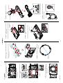
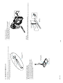
NEX-7/7K_L2
CCD Cleaning Jig (New)
(J-6082-663-A)
2 The dry cleaning cloth.
1 Souse the cleaning
cloth in ethyl alcohol.
<Cleaning Procedure for Tip of CCD Cleaning Jig>
1. Put the two cleaning cloths on a tray like below.
1 Souse the one cleaning cloth in ethyl alcohol.
2 Put the other cleaning cloth on a tray as it is dry.
2. Dab the tip of CCD cleaning jig at the cleaning cloth of 1 5 or 6 times.
* Do not slide the tip from right to left or up and down while dabbing.
3. Dab the tip of CCD cleaning jig at the cleaning cloth of 2 5 or 6 times.
* Do not slide from right to left or up and down while dabbing.
4. Wait until the tip will be dried completely.
CCD Cleaning Jig
CCD Cleaning Jig (Tip)
Protection Sheet
Note: Protection sheet is for preventing the scratch of a surface on the Jig (Tip).
The protection sheet may be come off the Jig when you take the Jig from a bag, but it is no problem.
<Preparation for Remedy>
If you use the new Jig (J-6082-663-A) below, make sure to clean the CCD Cleaning Jig (Tip) below before using, please.
3-2. CLEANING PROCEDURE OF OLPF
3-3E
OLPF
Cleaning Cloth
(J-6082-636-A)
Cut
Cleaning Jig
(J-6082-635-A)
EE3310
<ATTENTION>
If you cannot remove dirt with remedy above, cleaning by the following jig are used.
Soak a small amount of EE3310 (Liquid cleaner) after wrapping the cleaning cloth (J-6082-636-A) around the cleaning jig (J-6082-635-A).
<Cleaning Procedure for the OLPF>
1. Clean up the tip of CCD cleaning jig.
2. Dab the tip of CCD cleaning jig at the OLPF, and pull up straight.
* Do not slide from right to left or up and down while dabbing.
3. Repeat “3” several times to clean up.
4. According to service manual, check if there is dirt on the CCD.