1
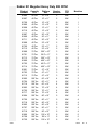
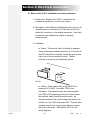
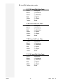
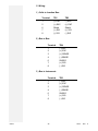
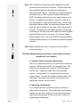
Instruction Manual
“Rodan RC”
Motor Truck Scale
Model : 6010 Series
6020 Series
6030 Series
FAIRBANKS
S C A L E S
© 1997-2012 by Fairbanks Scales Inc.
All rights reserved
50518
Revision 11 03/12
Amendment Record
Rodan RC
50518
Manufactured by Fairbanks Scales Inc.
821 Locust
Kansas City, Missouri 64106
Created
Issue #1
Issue #2
Issue #3
Issue #4
Issue #5
Issue #6
Issue #7
Issue #8
Issue #9
Issue #10
Revision 11
09/99
06/00
09/01
03/04
07/05
03/12
Product Update, Load Cell changes
Updated to the new Model Numbers
Added: EZ-Under Mount design
Added technical information and corrected drawings.
Revised replacement parts list.
Added changes for anti-rotation pins on the load cells ECR 253
Disclaimer
Every effort has been made to provide complete and accurate information in this manual. However, although this manual may
include a specifically identified warranty notice for the product, Fairbanks Scales makes no representations or warranties with
respect to the contents of this manual, and reserves the right to make changes to this manual without notice when and as
improvements are made.
50518
2
3/12
Rev. 11
50518
3
3/12
Rev. 11
Table of Contents
Section 1: Introduction . . . . . . . . . . . . . . . . . . . . . . . . . . . . . 5
Section 2: Description . . . . . . . . . . . . . . . . . . . . . . . . . . . . . 6
Rodan RC Field Pour Industrial Duty 60K DTAC . . . . . . . . 7
Rodan RC Field Pour Heavy Duty 60K DTAC . . . . . . . . . . 8
Rodan RC Field Pour Industrial Duty 80K DTAC . . . . . . . . 9
Rodan RC Field Pour Heavy Duty 80K DTAC . . . . . . . . . . 10
Rodan RC Steel Deck Industrial Duty 60K DTAC . . . . . . . 11
Rodan RC Steel Deck Heavy Duty 60K DTAC . . . . . . . . . 12
Rodan
Rodan
Rodan
Rodan
RC
RC
RC
RC
Steel Deck Industrial Duty 80K DTAC
Steel Deck Heavy Duty 80K DTAC . .
Megabar Heavy Duty 60K DTAC . . . .
Megabar Heavy Duty 80K DTAC . . . .
.
.
.
.
.
.
.
.
.
.
.
.
.
.
.
.
.
.
.
.
.
.
.
.
.
.
.
.
13
14
15
16
Section 3: Installation
A. Preparations for Installations, all models . . . . . . . . . . . . 17
B. Foundation
. . . . . . . . . . . . . . . . . . . . . . . . . . . . . 19
C. Setting the Modules . . . . . . . . . . . . . . . . . . . . . . . . . . . 20
Section 4: Field Pour Installation
A. Concrete Specifications . . . . . . . . . . . . . . . . . . . . . . . . 31
B. Shoring
. . . . . . . . . . . . . . . . . . . . . . . . . . . . . 31
C. Setting the field pour modules . . . . . . . . . . . . . . . . . . . 33
Section 5: Electrical Installation
A. Balance Box 21912, Installation for Analog Indicators . . 35
B. Load Cell wiring color codes . . . . . . . . . . . . . . . . . . . . 36
C. Wiring
. . . . . . . . . . . . . . . . . . . . . . . . . . . . . 37
D. Wiring SSCs and PPSs for the Intalogix system
E. SSC
.......................
F. Grounding, SSCs . . . . . . . . . . . . . . . . . . . . . . .
G. Indicator-to-PPS Cable Connection . . . . . . . . .
50518
4
.
.
.
.
.
.
.
.
.
.
.
.
.
.
.
.
.
.
.
.
.
.
.
.
39
40
40
40
03/12
Rev. 11
Section 6: Maintenance
Scale Maintenance . . . . . . . . . . . . . . . . . . . . . . . . . . . . . 41
Section 7: Parts & Part Replacement
A. Parts, Original Style . . . . . . . . . . . . . . . . . . . . . . . . . . . 42
B. Parts, E-Z Mount . . . . . . . . . . . . . . . . . . . . . . . .
C. Load Cells and Load Cell Hardware, ALL Models
D. “O” Rings , Actual Size . . . . . . . . . . . . . . . . . . . .
E. Replacing an RC Load Cell . . . . . . . . . . . . . . . .
.
.
.
.
.
.
.
.
.
.
.
.
.
.
.
.
.
.
.
.
42
43
44
45
F. General Load Cell Information . . . . . . . . . . . . . . . . . . . 46
Section 8: Accessories
A. Field Installed Rub Rail Installation . . . . . . . . . . . . . . . . 47
APPENDIX I: Foundation Check List . . . . . . . . . . . . . . . . . . . . . . 48
APPENDIX II: 4 Section Analog Scale . . . . . . . . . . . . . . . . . . . . . 50
APPENDIX III: 5 Section Analog Scale . . . . . . . . . . . . . . . . . . . . 48
APPENDIX IV: 4 Section Intalogix Scale . . . . . . . . . . . . . . . . . . . 48
50518
5
03/12
Rev. 11
Section 1: Introduction
This Instruction manual provides installation instructions for the Fairbanks
Modular Steel, Field-Pour, and Megabar™ model scales, in both the
Original and the EZ-Under-Mount designs.
For correct Rodan scale installation(s), use:
• Methods and Procedures FF-2267 / 101732 (Appendix I)
• The Certified prints/setting plans supplied with the scale
• This Instruction Manual, 50518
The concrete foundation work must be performed according to the Certified
prints issued for the specific customer and order number. (The name and
order number for the particular customer will be on the prints.)
50518
6
03/12
Rev. 11
Section 2: Description
The Modular Steel, Field Pour and Megabar™ truck scales are
available in various lengths from 10 to 100 feet and widths from 10' to 12'.
The scale is made up of modules of 10', 15', 20' or 23'-4" in length. All
modules are assembled and welded at the factory. Megabar™ models
have factory poured and cured concrete decks.
The scale should be located so that vehicles can approach and exit
the scale as easily as possible. The platform should be visible from the
instrument location. Drainage of surface water must be such that water
does not collect under the scale. Smooth and level approaches are
required at each end of the platform to reduce loading shock and facilitate
testing of the scale. Approaches must conform to the requirements of the
law in the state in which the scale is being installed. In the absence of
such laws the approaches must conform to paragraph UR.2.6 National
Institute of Standards and Technology Handbook 44, which states that the
first 10 feet must be level and on the same plane as the scale platform.
COC #: 96-089A2
50518
7
03/12
Rev. 11
Rodan RC Field Pour Industrial Duty 60K DTAC
50518
Product
Number
Capacity
Lbs
Platform
Size
Number
Sections
DTA
Lbs
Modules
90433
30 Ton
10’ x 10’
2
60K
1
90013
30 Ton
10’ x 11’
2
60K
1
90002
30 Ton
15’ x 10”
2
60K
1
90014
30 Ton
15’ x 11”
2
60K
1
90003
30 Ton
20’ x 10”
2
60K
1
90015
30 Ton
20’ x 11”
2
60K
1
90005
60 Ton
30’ x 10”
3
60K
2
90017
60 Ton
30’ x 11”
3
60K
2
90006
60 Ton
40’ x 10”
3
60K
2
90018
60 Ton
40’ x 11”
3
60K
2
90007
60 Ton
47’ x 10”
3
60K
2
90019
60 Ton
47’ x 11”
4
60K
2
90008
100 Ton
60’ x 10”
4
60K
3
90020
100 Ton
60’ x 11”
4
60K
3
90009
100 Ton
70’ x 10”
4
60K
3
90021
100 Ton
70’ x 11”
4
60K
3
90010
100 Ton
80’ x 10”
5
60K
4
90022
100 Ton
80’ x 11”
5
60K
4
90011
100 Ton
90’ x 10”
5
60K
4
90023
100 Ton
90’ x 11”
5
60K
4
90012
100 Ton
100’ x 10”
6
60K
5
90024
100 Ton
100’ x 11”
6
60K
5
8
03/12
Rev. 11
Rodan RC Field Pour Heavy Duty 60K DTAC
50518
Product
Number
Capacity
Lbs
Platform
Size
Number
Sections
DTA
Lbs
Modules
90373
30 Ton
10’ x 10”
2
60K
1
90025
30 Ton
10’ x 11”
2
60K
1
90374
30 Ton
15’ x 10”
2
60K
1
90026
30 Ton
15’ x 11”
2
60K
1
90375
30 Ton
20’ x 10”
2
60K
1
90027
30 Ton
20’ x 11”
2
60K
1
90376
30 Ton
23’ x 10”
2
60K
1
90028
30 Ton
23’ x 11”
2
60K
1
90377
60 Ton
30’ x 10”
3
60K
2
90029
60 Ton
30’ x 11”
3
60K
2
90378
60 Ton
40’ x 10”
3
60K
2
90030
60 Ton
40’ x 11”
3
60K
2
90379
60 Ton
47’ x 10”
3
60K
2
90031
60 Ton
47’ x 11”
3
60K
2
90380
100 Ton
60’ x 10”
4
60K
3
90032
100 Ton
60’ x 11”
4
60K
3
90381
100 Ton
70’ x 10”
4
60K
3
90033
100 Ton
70’ x 11”
4
60K
3
90382
100 Ton
80’ x 10”
5
60K
4
90034
100 Ton
80’ x 11”
5
60K
4
90383
100 Ton
90’ x 10”
5
60K
4
90035
100 Ton
90’ x 11”
5
60K
4
90384
100 Ton
100’ x 10”
6
60K
5
90036
100 Ton
100’ x 11”
6
60K
5
9
03/12
Rev. 11
Rodan RC Field Pour Industrial Duty 80K DTAC
Product
Number
90037
90049
90061
90038
90050
90062
90039
90051
90063
90040
90052
90064
90041
90053
90065
90042
90054
90066
90043
90055
90067
90044
90056
90068
90045
90057
90069
90046
90058
90070
90047
90059
90071
90048
90060
90072
50518
Capacity
Lbs
40 Ton
40 Ton
40 Ton
40 Ton
40 Ton
40 Ton
40 Ton
40 Ton
40 Ton
40 Ton
40 Ton
40 Ton
70 Ton
70 Ton
70 Ton
70 Ton
70 Ton
70 Ton
70 Ton
70 Ton
70 Ton
100 Ton
100 Ton
100 Ton
100 Ton
100 Ton
100 Ton
100 Ton
100 Ton
100 Ton
100 Ton
100 Ton
100 Ton
100 Ton
100 Ton
100 Ton
Platform
Size
10’ x 10”
10’ x 11”
10’ x 12”
15’ x 10”
15’ x 11”
15’ x 12”
20’ x 10”
20’ x 11”
20’ x 12”
23’ x 10”
23’ x 11”
23’ x 12”
30’ x 10”
30’ x 11”
30’ x 12”
40’ x 10”
40’ x 11”
40’ x 12”
47’ x 10”
47’ x 11”
47’ x 12”
60’ x 10”
60’ x 11”
60’ x 12”
70’ x 10”
70’ x 11”
70’ x 12”
80’ x 10”
80’ x 11”
80’ x 12”
90’ x 10”
90’ x 11”
90’ x 12”
100’ x 10”
100’ x 11”
100’ x 12”
10
Number
Sections
2
2
2
2
2
2
2
2
2
2
2
2
3
3
3
3
3
3
3
3
3
4
4
4
4
4
4
5
5
5
5
5
5
6
6
6
DTA
Lbs
80K
80K
80K
80K
80K
80K
80K
80K
80K
80K
80K
80K
80K
80K
80K
80K
80K
80K
80K
80K
80K
80K
80K
80K
80K
80K
80K
80K
80K
80K
80K
80K
80K
80K
80K
80K
Modules
1
1
1
1
1
1
1
1
1
1
1
1
2
2
2
2
2
2
2
2
2
3
3
3
3
3
3
4
4
4
4
4
4
5
5
5
03/12
Rev. 11
Rodan RC Field Pour Heavy Duty 80K DTAC
50518
Product
Number
91841
91865
Capacity
Lbs
40 Ton
40 Ton
Platform
Size
10’ x 10”
10’ x 11”
Number
Sections
2
2
DTA
Lbs
80K
80K
Modules
91889
91842
91866
91890
40 Ton
40 Ton
40 Ton
40 Ton
10’ x 12”
15’ x 10”
15’ x 11”
15’ x 12”
2
2
2
2
80K
80K
80K
80K
1
1
1
1
91843
91867
91891
91844
40 Ton
40 Ton
40 Ton
40 Ton
20’ x 10”
20’ x 11”
20’ x 12”
23’ x 10”
2
2
2
2
80K
80K
80K
80K
1
1
1
1
91868
91892
91845
40 Ton
40 Ton
70 Ton
23’ x 11”
23’ x 12”
30’ x 10”
2
2
3
80K
80K
80K
1
1
2
91869
91893
91846
91870
70 Ton
70 Ton
70 Ton
70 Ton
30’ x 11”
30’ x 12”
40’ x 10”
40’ x 11”
3
3
3
3
80K
80K
80K
80K
2
2
2
2
91894
91847
91871
91895
70 Ton
70 Ton
70 Ton
70 Ton
40’ x 12”
47’ x 10”
47’ x 11”
47’ x 12”
3
3
3
3
80K
80K
80K
80K
2
2
2
2
91848
91872
91896
91849
100 Ton
100 Ton
100 Ton
100 Ton
60’ x 10”
60’ x 11”
60’ x 12”
70’ x 10”
4
4
4
4
80K
80K
80K
80K
3
3
3
3
91873
91897
91850
91874
91898
100 Ton
100 Ton
100 Ton
100 Ton
100 Ton
70’ x 11”
70’ x 12”
80’ x 10”
80’ x 11”
80’ x 12”
4
4
5
5
5
80K
80K
80K
80K
80K
3
3
4
4
4
91851
91875
91899
100 Ton
100 Ton
100 Ton
90’ x 10”
90’ x 11”
90’ x 12”
5
5
5
80K
80K
80K
4
4
4
91852
91876
91900
100 Ton
100 Ton
100 Ton
100’ x 10”
100’ x 11”
100’ x 12”
6
6
6
80K
80K
80K
5
5
5
11
1
1
03/12
Rev. 11
Rodan RC Steel Deck Industrial Duty 60K DTAC
50518
Product
Number
Capacity
Lbs
Platform
Size
Number
Sections
DTA
Lbs
Modules
90157
30 Ton
10’ x 10”
2
60K
1
90217
30 Ton
10’ x 11”
2
60K
1
90158
30 Ton
15’ x 10”
2
60K
1
90218
30 Ton
15’ x 11”
2
60K
1
90159
30 Ton
20’ x 10”
2
60K
1
90219
30 Ton
20’ x 11”
2
60K
1
90160
30 Ton
23’ x 10”
2
60K
1
90220
30 Ton
23’ x 11”
2
60K
1
90161
60 Ton
30’ x 10”
3
60K
2
60221
60 Ton
30’ x 11”
3
60K
2
90162
60 Ton
40’ x 10”
3
60K
2
90222
60 Ton
40’ x 11”
3
60K
2
90163
60 Ton
47’ x 10”
3
60K
2
90223
60 Ton
47’ x 11”
3
60K
2
90164
100 Ton
60’ x 10”
4
60K
3
90224
100 Ton
60’ x 11”
4
60K
3
90165
100 Ton
70’ x 10”
4
60K
3
90225
100 Ton
70’ x 11”
4
60K
3
90166
100 Ton
80’ x 10”
5
60K
4
90226
100 Ton
80’ x 11”
5
60K
4
90167
100 Ton
90’ x 10”
5
60K
4
90227
100 Ton
90’ x 11”
5
60K
4
90168
100 Ton
100’ x 10”
6
60K
5
90228
100 Ton
100’ x 11”
6
60K
5
12
03/12
Rev. 11
Rodan RC Steel Deck Heavy Duty 60K DTAC
50518
Product
Number
Capacity
Lbs
Platform
Size
Number
Sections
DTA
Lbs
Modules
90097
30 Ton
10’ x 10”
2
60K
1
90109
30 Ton
10’ x 11”
2
60K
1
90098
30 Ton
15’ x 10”
2
60K
1
90110
30 Ton
15’ x 11”
2
60K
1
90099
30 Ton
20’ x 10”
2
60K
1
90111
30 Ton
20’ x 11”
2
60K
1
90100
30 Ton
23’ x 10”
2
60K
1
90112
30 Ton
23’ x 11”
2
60K
1
90101
60 Ton
30’ x 10”
3
60K
2
90113
60 Ton
30’ x 11”
3
60K
2
90102
60 Ton
40’ x 10”
3
60K
2
90114
60 Ton
40’ x 11”
3
60K
2
90103
60 Ton
47’ x 10”
3
60K
2
90115
60 Ton
47’ x 11”
3
60K
2
90104
100 Ton
60’ x 10”
4
60K
3
90116
100 Ton
60’ x 11”
4
60K
3
90105
100 Ton
70’ x 10”
4
60K
3
90117
100 Ton
70’ x 11”
4
60K
3
90106
100 Ton
80’ x 10”
5
60K
4
90118
100 Ton
80’ x 11”
5
60K
4
60107
100 Ton
90’ x 10”
5
60K
4
90119
100 Ton
90’ x 11”
5
60K
4
90108
100 Ton
100’ x 10”
6
60K
5
90120
100 Ton
100’ x 11”
6
60K
5
13
03/12
Rev. 11
Rodan RC Steel Deck Industrial Duty 80K DTAC
50518
Product
Number
90121
90133
Capacity
Lbs
40 Ton
40 Ton
Platform
Size
10’ x 10”
10’ x 11”
Number
Sections
2
2
DTA
Lbs
80K
80K
Modules
90145
90122
90134
90146
40 Ton
40 Ton
40 Ton
40 Ton
10’ x 12”
15’ x 10”
15’ x 11”
15’ x 12”
2
2
2
2
80K
80K
80K
80K
1
1
1
1
90123
90111
90147
90124
40 Ton
40 Ton
40 Ton
40 Ton
20’ x 10”
20’ x 11”
20’ x 12”
23’ x 10”
2
2
2
2
80K
80K
80K
80K
1
1
1
1
90136
90148
90125
40 Ton
40 Ton
70 Ton
23’ x 11”
23’ x 12”
30’ x 10”
2
2
3
80K
80K
80K
1
1
2
90137
90149
90126
90138
70 Ton
70 Ton
70 Ton
70 Ton
30’ x 11”
30’ x 12”
40’ x 10”
40’ x 11”
3
3
3
3
80K
80K
80K
80K
2
2
2
2
90150
90127
90139
90151
70 Ton
70 Ton
70 Ton
70 Ton
40’ x 12”
47’ x 10”
47’ x 11”
47’ x 12”
3
3
3
3
80K
80K
80K
80K
2
2
2
2
90128
90140
90152
90129
100 Ton
100 Ton
100 Ton
100 Ton
60’ x 10”
60’ x 11”
60’ x 12”
70’ x 10”
4
4
4
4
80K
80K
80K
80K
3
3
3
3
90141
90153
90130
90142
90154
100 Ton
100 Ton
100 Ton
100 Ton
100 Ton
70’ x 11”
70’ x 12”
80’ x 10”
80’ x 11”
80’ x 12”
4
4
5
5
5
80K
80K
80K
80K
80K
3
3
4
4
4
90131
90143
90155
100 Ton
100 Ton
100 Ton
90’ x 10”
90’ x 11”
90’ x 12”
5
5
5
80K
80K
80K
4
4
4
90132
90144
90156
100 Ton
100 Ton
100 Ton
100’ x 10”
100’ x 11”
100’ x 12”
6
6
6
80K
80K
80K
5
5
5
14
1
1
03/12
Rev. 11
Rodan RC Steel Deck Heavy Duty 80K DTAC
Product
Number
91769
91793
91817
91770
91794
91818
91771
91795
91819
91772
91796
91820
91773
91797
91821
91774
91798
91822
91775
91799
91823
91776
91800
91824
91777
91801
91825
91778
91802
91826
91779
91803
91827
91780
91804
91828
50518
Capacity
Lbs
40 Ton
40 Ton
40 Ton
40 Ton
40 Ton
40 Ton
40 Ton
40 Ton
40 Ton
40 Ton
40 Ton
40 Ton
70 Ton
70 Ton
70 Ton
70 Ton
70 Ton
70 Ton
70 Ton
70 Ton
70 Ton
100 Ton
100 Ton
100 Ton
100 Ton
100 Ton
100 Ton
100 Ton
100 Ton
100 Ton
100 Ton
100 Ton
100 Ton
100 Ton
100 Ton
100 Ton
Platform
Size
10’ x 10”
10’ x 11”
10’ x 12”
15’ x 10”
15’ x 11”
15’ x 12”
20’ x 10”
20’ x 11”
20’ x 12”
23’ x 10”
23’ x 11”
23’ x 12”
30’4” x 10”
30’4” x 11”
30’4” x 12”
40’4” x 10”
40’4” x 11”
40’4” x 12”
47’ x 10”
47’ x 11”
47’ x 12”
60’ x 10”
60’ x 11”
60’ x 12”
70’ x 10”
70’ x 11”
70’ x 12”
80’ x 10”
80’ x 11”
80’ x 12”
90’ x 10”
90’ x 11”
90’ x 12”
100’ x 10”
100’ x 11”
100’ x 12”
15
Number
Sections
2
2
2
2
2
2
2
2
2
2
2
2
3
3
3
3
3
3
3
3
3
4
4
4
4
4
4
5
5
5
5
5
5
6
6
6
DTA
Lbs
80K
80K
80K
80K
80K
80K
80K
80K
80K
80K
80K
80K
80K
80K
80K
80K
80K
80K
80K
80K
80K
80K
80K
80K
80K
80K
80K
80K
80K
80K
80K
80K
80K
80K
80K
80K
Modules
1
1
1
1
1
1
1
1
1
1
1
1
2
2
2
2
2
2
2
2
2
3
3
3
3
3
3
4
4
4
4
4
4
5
5
5
03/12
Rev. 11
Rodan RC Megabar Heavy Duty 60K DTAC
50518
Product
Number
Capacity
Lbs
Platform
Size
Number
Sections
DTA
Lbs
Modules
90181
30 Ton
10’ x 10”
2
60K
1
90193
30 Ton
10’ x 11”
2
60K
1
90182
30 Ton
15’ x 10”
2
60K
1
90194
30 Ton
15’ x 11”
2
60K
1
90183
30 Ton
20’ x 10”
2
60K
1
90195
30 Ton
20’ x 11”
2
60K
1
90184
30 Ton
23’ x 10”
2
60K
1
90196
30 Ton
23’ x 11”
2
60K
1
90185
60 Ton
30’ x 10”
3
60K
2
90197
60 Ton
30’ x 11”
3
60K
2
90186
60 Ton
40’ x 10”
3
60K
2
90198
60 Ton
40’ x 11”
3
60K
2
90187
60 Ton
47’ x 10”
3
60K
2
90199
60 Ton
47’ x 11”
3
60K
2
90188
100 Ton
60’ x 10”
4
60K
3
90200
100 Ton
60’ x 11”
4
60K
3
90189
100 Ton
70’ x 10”
4
60K
3
90201
100 Ton
70’ x 11”
4
60K
3
90190
100 Ton
80’ x 10”
5
60K
4
90202
100 Ton
80’ x 11”
5
60K
4
90191
100 Ton
90’ x 10”
5
60K
4
90203
100 Ton
90’ x 11”
5
60K
4
90192
100 Ton
100’ x 10”
6
60K
5
90204
100 Ton
100’ x 11”
6
60K
5
16
03/12
Rev. 11
Rodan RC Megabar Heavy Duty 80K DTAC
50518
Product
Number
Capacity
Lbs
Platform
Size
Number
Sections
DTA
Lbs
Modules
91685
40 Ton
10’ x 10”
2
80K
1
91697
40 Ton
10’ x 11”
2
80K
1
91709
40 Ton
10’ x 12”
2
80K
1
91686
40 Ton
15’ x 10”
2
80K
1
91698
40 Ton
15’ x 11”
2
80K
1
91710
40 Ton
15’ x 12”
2
80K
1
91687
40 Ton
20’ x 10”
2
80K
1
91699
40 Ton
20’ x 11”
2
80K
1
91711
40 Ton
20’ x 12”
2
80K
1
91688
40 Ton
23’ x 10”
2
80K
1
91700
40 Ton
23’ x 11”
2
80K
1
91712
40 Ton
23’ x 12”
2
80K
1
91689
70 Ton
30’4” x 10”
3
80K
2
91701
70 Ton
30’4” x 11”
3
80K
2
91713
70 Ton
30’4” x 12”
3
80K
2
91690
70 Ton
40’4” x 10”
3
80K
2
91702
70 Ton
40’4” x 11”
3
80K
2
91714
70 Ton
40’4” x 12”
3
80K
2
91691
70 Ton
47’ x 10”
3
80K
2
91703
70 Ton
47’ x 11”
3
80K
2
91715
70 Ton
47’ x 12”
3
80K
2
91692
100 Ton
60’ x 10”
4
80K
3
91704
100 Ton
60’ x 11”
4
80K
3
91716
100 Ton
60’ x 12”
4
80K
3
91693
100 Ton
70’ x 10”
4
80K
3
91705
100 Ton
70’ x 11”
4
80K
3
91717
100 Ton
70’ x 12”
4
80K
3
91694
100 Ton
80’ x 10”
5
80K
4
91706
100 Ton
80’ x 11”
5
80K
4
91718
100 Ton
80’ x 12”
5
80K
4
91695
100 Ton
90’ x 10”
5
80K
4
91707
100 Ton
90’ x 11”
5
80K
4
91719
100 Ton
90’ x 12”
5
80K
4
91696
100 Ton
100’ x 10”
6
80K
5
91708
100 Ton
100’ x 11”
6
80K
5
91720
100 Ton
100’ x 12”
6
80K
5
17
03/12
Rev. 11
Section 3: Installation
Installation consists of the following:
• Foundation check, layout, and base plate setting
• Tools, materials, documentation, and a crane
• Setting the modules
• Setting the modules on load cells
Note: Original style Rodans and the 'EZ-Under-Mount' style differ
in installation procedures. Additional installation instructions
are provided for the Field-Pour deck in Section 4 of this manual.
A. Preparations for Installations, all Models:
Tools, Equipment, and Materials Required:
1. Certified Prints
2. A mobile crane of sufficient capacity to safely lift and place the
weighbridge modules.
Approximate maximum weights:
• Steel modules
4 tons
• MegaBar™ modules - 6.5 tons
• Field pour Modules - 2.5 tons
w/concrete - 25K - 30K lbs
+/-5%
3. Four (4) equal length (20 ft) lifting chains or cables with hooks to
safely attach to the modules near each corner
NOTE: These MUST be requested in advance from the Crane Service
Company!
4. Machinists levels (starrett # 134 & 132-6)
5. Hand tools
6. Hammer Drill with 5/8" bit, 16" long
50518
18
03/12
Rev. 11
7. Hydraulic jacks-Use hydraulic jacks that have sufficient capacity +
a safety factor for the model scale you are installing.
• Steel modules
10 ton hydraulic jacks (2)
•
•
•
•
15 ton hydraulic jacks (2)
30 ton hydraulic jacks (2)
30 ton jacks
Hand pump
MegaBar™ modules
Field pour Modules
93296
93297
• 93298
Hose, 6’
8. 100' steel tape measure
9. Stringline or chalkline (both)
10. Prybars
11. Quality grease and anti-seize
12. Load cell locating tools, one for each load cell,
available from CPD
Part No. 71717 for 5 ½"
Part No. 76623 for 7"
13. 4" x 4" x 12' timbers (supplied) for field pour models
50518
19
03/12
Rev. 11
B. Foundation:
Before installing any part of the scale, the foundation must be checked for
accuracy using Foundation Inspection, Field Check List, FF-2267 / 101732
(see Appendix I).
1. Layout and position the base plates in the proper locations using
the Methods & Procedures and Certified prints. Each base plate
must be level and in full contact with the top of the pier.
Adjustments can be made by chipping the concrete or grouting
(thinly, enough to fill in small imperfections) under the base
plates. A maximum of +/- 1/8" adjustment is allowed.
2. Re-check the locations of each base plate against the Certified
Prints.
• Original Rodan types: Insert two ½" roll pins into each
base plate for anti-rotation. Position the plates with pins
toward the OUTSIDE. This will leave the load cell cable and
the anti-rotation pin exiting the cell to the INSIDE. It is NOT
necessary to install base plate anchors at this time.
• E-Z Under Mounts: Insert two ½" roll pins into each
lower cup for anti-rotation.
WARNING: The base plate's center anchor bolt (5/8" x 6") MUST be
installed in each plate at this time.
3. For 5½" and 7" cell cups, grease and install the inner "O" ring in
each cup if they are not already installed. On all cups, grease
the large outer "O" rings, then install one in the groove on the
outside of each cup. Put a 3/16" shim on the lower cups, grease
the outsides, then insert them into the base plates. Lower cups
for 5½" or 7” load cells have a pin which must be aligned
between the two roll pins in the base plate.
4. Place the upper cup with greased "O" ring on the edge of the the
upper foundation next to each base plate.
5. Place the proper sized load cell locating tool next to each base
plate.
50518
20
03/12
Rev. 11
Locating Tool
Bearing
Cups
“O” Rings
Shim
50583-5
Note: If this is a field pour installation,
see Section 4 of this manual.
C. Setting The Modules:
1. Preparing The Modules For Lifting
• Original Rodan types:
The original style modules must have lifting brackets installed at
each corner before they can be lifted. Use only the high-strength
bolts provided or parts from the factory. Tighten the bolts as tight
as possible.
4183
50518
21
03/12
Rev. 11
17'
(Min.)
45 or more
50583-4
• E-Z Under Mounts: The newer modules are complete with
channel pieces welded to the sides for attaching lifting hooks.
NO bolts are needed.
50518-23a
50518
22
03/12
Rev. 11
2. Setting The Center Module:
The center module is always set first. The center module will have
four load cells to install; all other modules will have two load cells.
The modules must be placed in the proper order and aligned in the
foundation so that all modules fit correctly.
• Original Rodan types: These scales do NOT have a left-right
orientation and have 'unmarked' ends. The center module may be
installed facing either direction as long as it is in the center. The
other modules will set upon the center module from either end.
• E-Z Under Mounts: These scales HAVE a definite orientation
because the cable conduit is welded to 1 side only. These
modules have 'unmarked' ends as well. The conduit side of the
center module should face the 'home-run' conduit; the conduit side
of the other modules must face the same way.
Both Types:
a. Place blocks that will set the modules at a height slightly
less than the finished height as safety blocks, or for setting
modules on.
b. Lift the center module to a location above the four center
load cell base plates.
OPTION 1: You may set the module directly on the locating
tools and the blocks will act as safety stands.
• Install a Load Cell Bearing Cup with "O" rings
into the upper receiver of each corner,
grease will help hold the cup in place.
• Insert the upper end of the locating tool into
the upper cup on the module.
• Lower the module while holding the locating
tool upright and guiding the bottom of the
tool into the lower cup.
50518
23
03/12
Rev. 11
• When the center module is set on all four
locating tools, keep tension on the cables
until the module is centered and straight.
• Use hydraulic jacks to lift the unit slightly and
shift the base plates to get the locating tools
PLUMB and the top and bottom flanges
FLUSH with the sides of the cup.
OPTION 2: Set the modules on the blocks first, then onto
locating tools.
• When the module is set on the blocks, keep
tension on the cables until the module is
properly aligned.
• Use hydraulic jacks to lift the unit slightly,
then install the locating tools. Shift the base
plates to get the tools PLUMB and the top
and bottom flanges FLUSH with the sides of
the cup.
c. Measure from each side of each end of the module to the
end walls, to be certain the module is plumb and square
before removing tension.
d. Once the tension on the lift cables is released, remove the
lift brackets and/or hooks.
50518
24
03/12
Rev. 11
3. Setting End Modules, Both Types:
a. Interlocking Pin
• Original Rodan types: Drive an interlocking pin into each
load cell bracket of the center module.
50518-4
• E-Z Under Mounts: No action required.
50518
25
03/12
Rev. 11
b. Module Placement
• Original Rodan types: Guide the modules into place with
the supporting blocks on the end of the module coming to
rest on the center module load cell bracket interlocking
pins. Lower the other end of the module onto the load cell
locating tools or blocks.
4018
• E-Z Under Mounts: Guide the modules into place with the
supporting blocks on the end of the module coming
to rest on the supporting blocks of the center module.
Lower the other end of the module onto the load cell
locating tools or blocks.
50518-24
50518
26
03/12
Rev. 11
4. Before releasing tension on the cables, check the alignment of
the end modules to the center module and to the end wall.
• Original Rodan types: Ensure end modules are aligned
with the center module and the foundation.
• E-Z Under Mounts: Use the provided shims to set height
and fill any gaps on the supporting blocks to get the
modules aligned.
5. Connecting the Modules:
• Original Rodan types: Bolt the modules' channels together
using the ½" x 4" x 6" spacers and 1" x 3" bolts. Insert the
½" x 4" x 6" spacer plates between the channels. The
bolts go through the back-to-back channels and the spacer.
Snug the bolts, but do not tighten yet.
Spacer
Bolt
50518d
50518
27
03/12
Rev. 11
• E-Z Under Mounts: Bolt the modules together using the 11/8" x
4½" bolt, lock washer, flat washers and nut provided. Remember
to shim the supporting blocks if necessary to align modules.
50518-25
Warning: Module-to-module bolts MUST be installed correctly
and torqued properly after all lifting, etc. is
completed. Do NOT substitute or omit bolts.
6. Checking Adjustment
a. Adjust End Checking
• Original Rodan Type: Use the end checking shims provided to
adjust end checking so that they touch and prevent
movement.
TOP VIEW
Scale
Shim to 1/8" nominal gap.
Check Block
Urethane Check Pad
End Coping Angle
Shim(s)
Coupling
Nuts
50518
28
50583-8
03/12
Rev. 11
• E-Z Under Mounts: Adjust the End Checking Bolt so that
they touch and prevent movement.
50581-26
b. Install the side checking brackets:
• Original Rodan types: Bolt the brackets onto the end
copings per the Certified drawings. Set the bolts so that
they touch the channels they bump against.
• E-Z Under Mounts: Bolt the brackets to the end checking
plates embedded in the end walls per Certified prints. Set
the bolts so that they touch the channels they bump against.
7. Base Plate Completion:
• Original Rodan types: Check that all locating tools are properly
aligned and flush with the receiver cups. Drill the holes for the
base plate anchors using a hammer-drill and the 5/8" drill bit. Tap
the anchors into clean holes and tighten the nuts securely.
• E-Z Under Mounts: Check that all locating tools are properly
aligned and flush with the receiver cups. Drill the holes for the
outside base plate anchors using a hammer-drill and the 5/8"
drill bit. Tap the anchors into clean holes and tighten the nuts
securely.
50518
29
03/12
Rev. 11
8. Installing Load Cells:
Note: Field-Pour scales are poured, formed and cured with locating
tools in place. Do NOT install load cells until cure strength is
reached (typically 28-30 days; use a core sample to confirm).
a. Unpack the load cells and mark each calibration
certificate with the cell location/position.
b. Starting at one end of the assembled platform,
place hydraulic jacks at the corners so the section
can be lifted off the locating tool (2 hydraulic jacks
may be required).
c. Lift the platform so the load cell locating tool can be
removed from the upper and lower bearing cups.
Once removed, fill both cups with grease.
Caution: Use eye protection! Grease can 'shoot' out of the cup at high
velocity!
d. For 6” or 71/2” Load Cells, insert the load cell's upper end
into the upper cup, and align so the anti-rotation pin in the
cell goes between the two roll pins in the baseplate. The
anti-rotation pin should be located on the cable entry side
of the load cell.
For 51/2” or 7” load cells, the bottom of the cell has two
flatsides which must be aligned with the flats in the lower
cup. Carefully lower the scale (hydraulic jacks) while
seating the bottom of the cell into the lower cup.
Check the scale's level and height, particularly at the
approaches. Use the load cell shims provided to adjust
load cell cups for correct height and to ensure that all cells
share the proper amount of load. Center section cells will
have up to twice the deadload of end section cells.
50518
30
03/12
Rev. 11
e. Once satisfied with height and level, tighten the
module-to-module bolts.
• Original Rodan types: The bolts must be torqued to
690 ft lbs.
• E-Z Under Mounts: The bolts must be torqued to
500 ft lbs.
f. Load cell cables:
• Original Rodan types: Route the load cell cables through
the holes in the channels to the SSC/PPS mounting bar
location in the center. Install the strain relief 'clamps' for
load cell cables on the strain relief base that is welded
onto the scale.
• E-Z Under Mounts: Route the 'far-side' load cell cables to
the conduits that go under the scale. Install the strain relief
'clamps' for load cell cables on the strain relief base that is
welded onto the scale, then run the cable end through the
conduits to the PPS/SSC mounting bar locations on the side.
9. Final Checking Adjustment:
a. Adjust End Checking
• Original Rodan types: Remove shims on end checking to
allow 1/16” to 1/8” clearance
• E-Z Under Mount:Adjust the End Checking Bolts to allow
1/16” to 1/8” clearance
b. Adjust side checking bolts to allow 1/16” clearance from
channel
50518
31
03/12
Rev. 11
Section 4: Field Pour Installation
The Field Pour modules' installation is much the same as the other
models, with some minor variations. The basic procedure is to install the
foundation for the scale, install the base plates, position and level the
shoring, install the platform modules with locator tools in place, pour the
deck, cure the concrete, then install the load cells.
A. Concrete Specifications:
Use the Certified Prints for all concrete specifications.
B. Shoring:
The recommended shoring is made up of the provided 4" x 4"
timbers 12 feet long. The "crown" of the shoring timbers should be
up. The actual dimensions of the timbers will depend on the
distance from the foundation floor to the bottom of the modules.
Shims should be placed under each end and center of the shoring
beams to achieve proper elevation. The shoring timbers should be
located equally spaced between the load cells.
See drawing on following page.
50518
32
03/12
Rev. 11
8-27
50518
33
03/12
Rev. 11
C. Setting the field pour modules:
1. The shoring timbers should be placed before setting scale
modules. Using the approach walls as the reference, place
the shoring timbers so they will be at the same elevation as
the bottom of the weigh bridge. A tight string between the
approach walls could be used.
2. Install the modules as outlined in Section 2C of this
manual, starting with the center module.
WARNING: The modules MUST be set on loading tools.
Do Not support load cell bracket with lumber, as this will
cause warping.
3. Wedge additional shims as required under the end of the
shoring timbers to ensure tight contact between the scale
frame and the shoring.
Caution: Make sure the edge beams of the scale are straight and
not bowed down, or in, before pouring the concrete deck. Do not
install the load cells before the concrete deck is cured.
4. Pour the concrete. A spud-type vibrator is required to
remove any air bubbles and to work the material into all of
the corners.
5. A rough "broom" finish is recommended. Crown concrete
1/4" to allow drainage. Allow the concrete to cure until the
required minimum strength as specified on the Certified
Prints is achieved.
Caution: At the time the deck is poured, samples must be taken for
later testing. At the end of 14 days, test the first sample. A sample
must pass the test at 4,000 psi before the scale can be placed into
service. A copy of the test report must be retained as part of the
customer record in the service center or distributor location,
otherwise warranty will be void.
6. After the concrete has cured, remove all of the shoring.
The modules will have to be lifted so the shoring can be
removed.
50518
34
03/12
Rev. 11
Warning : Place hydraulic jacks ONLY at the CORNERS of the
modules. Hydraulic jacks must be placed on opposite sides to
lift the module in a level position. Lifting mid-span or between
load cells will cause cracks in the concrete.
7. Install the load cells in place of the locator tools.
8. Set end wall checking at 1/8" maximum, 1/16" minimum gap.
Set side wall checking at 1/16" gap.
50518
35
03/12
Rev. 11
Section 5: Electrical Installation
A. Balance Box 21912, Installation for Analog Indicators:
1. Introduction: Balance box 21912 is intended to be
installed at the platform, one box per section.
2. Description: Each Stainless Steel balance box has four (4)
terminal blocks to connect two (2) load cells and two (2)
cables for connection to the analog instrument. Load cells
and sections are adjusted by means of adjusting
potentiometers.
3. Installation:
a. Boxes: The box has 'tabs' for bolting to adapters
either in the space between modules, or on the side of
the EZ Under Mount modules. Attach the ground wire
lug to one of the mounting bolt studs. Tighten
securely to provide a good electrical ground.
50518b
b. Wiring: Cable used in ALL wiring MUST be a
minimum of 18 AWG. Use cable 17204 or an
equivalent. The balance boxes are interconnected
from TB4 to TB3 beginning at the end section where
the interface cable conduit enters the scale. An
alternate method if the conduit enters the scale in the
middle is to use 14478 Instrument SVP. This will allow
separate connections to go in each direction toward
the ends of the scale. See Bulletin 50513 for the
wiring diagrams.
50518
36
03/12
Rev. 11
B. Load Cell wiring color codes:
5 ½" RC Load Cell Color Code:
Color
Description
Black
(-) Excitation
Green
(+) Excitation
Red
White
Yellow
(-) Signal
(+) Signal
Shield
6" RC Load Cell Color Code:
Color
Description
Black
(-) Excitation
Red
White
Green
Yellow
(+) Excitation
(-) Signal
(+) Signal
Shield
7" RC Load Cell Color Code:
Color
Black
Green
Description
(-) Excitation
(+) Excitation
Red
White
Yellow
(-) Signal
(+) Signal
Shield
7 ½" RC Load Cell Color Code:
Color
Description
50518
Black
Green
Red
(-) Excitation
(+) Excitation
(-) Signal
White
Yellow
(+) Signal
Shield
37
03/12
Rev. 11
C. Wiring:
1.) Cells to Junction Box:
Terminal
1
2
6
TB1
(-) EXC
(+) EXC
Shield
TB2
(-) EXC
(+) EXC
Shield
7
8
(+) SIG
(-) SIG
(+) SIG
(-) SIG
2.) Box to Box:
Terminal
1
TB4
(-) EXC
2
3
4
6
(+) EXC
(+) SENSE
(-) SENSE
SHIELD
7
8
(+) SIG
(-) SIG
3.) Box to Instrument:
50518
Terminal
1
2
3
TB3
(-) EXC
(+) EXC
(+) SENSE
4
6
7
(-) SENSE
SHIELD
(+) SIG
8
(-) SIG
38
03/12
Rev. 11
Note: The Full Electronic scales have been designed to provide
protection from the effects of moisture. The load cells have
been calibrated with the cable attached, therefore the
cable should NOT be cut. The cable is connected directly to
the balance box or SSC through a sealed bushing which
MUST be tightened with pliers to keep water/moisture out of
the box. All cabling should have a "drip loop" at the cell or
box entry location to help prevent water entry. On all boxes,
particularly Stainless Steel, the black plastic fittings have "O"
rings that can be forced out of position if the bushing itself is
not tight. To prevent this, first tighten the inner nut securing
the bushing in the hole, then insert cable and carefully tighten
gland with pliers until it is very snug. Do not over-tighten
where bushing 'turns' . The cover MUST be secured with ALL
screws tightened properly (18-20 in/lbs) for protection against
moisture.
Note: Balance Boxes must have 1 pit ground rod in the pit for
proper connection.
CAUTION: Without adequate ground(s), surge voltage protection
installation is not complete.
4.) Indicator Cable Connection, Balance Box
The two (2) cables from the two (2) center section boxes will
enter the 14478 Instrument SVP and terminate there. The
cable from the indicator will connect at 14478 Instrument
SVP as well. Prepare the cable ends in the standard
manner. Use Appendix II for wiring instructions of all pit
balance boxes. Connect the indicator interface cable to the
instrument in the scale house per the instructions in the
appropriate indicator service manual.
5.) Adjusting cells/sections:
Try to install load cells of matching outputs in sections to
reduce side-to-side errors. When calibrating, place weights
directly over the cell or directly on the section being tested.
Adjust the potentiometers for the correct cell or section to
compensate for differences.
50518
39
03/12
Rev. 11
6.) Cover Plates, Original Style:
The cover plates bridge the gap between modules. The
plates are held in place with ¾" x 1 ½" bolts. Use anti-seize
or grease on the bolts and bolt holes.
D. Wiring SSCs and PPSs for Intalogix™ systems:
1. Introduction:
Intalogix™ systems utilize smart sectional controllers (SSCs) and pit
power supplies (PPSs) for load cell excitation and signal
processing.
2. Description:
There is one (1) SSC per section and one (1) PPS for the entire
platform (unless the number and resistance of the cells require a
second pit power supply). SSC boxes have four (4) terminals two
(2) for load cells and two (2) for "inter connecting" to other SSC
boxes or terminating to a pit power supply. All cell/section/scale
adjustments are made via the Intalogix™ system instrument.
3. Installation:
a) Boxes: The box has 'tabs' for bolting to adapters either in
the space between modules, or on the side of the EZ Under
Mount modules.
50518b
b) Wiring: Cable used in all wiring must be a minimum of 18
AWG. Use cable 17204 or 17246. Use appropriate service
manual for the Indicator being installed, or Appendix III to
connect PPSs and SSCs.
50518
40
03/12
Rev. 11
Note: Intalogix™ installations utilize a different numbering system
for load cells because of digital addressing of the SSCs.
Number cells as follows: With respect to the following starting
position, face the platform from where the indicator is
located. The cell at the upper left (far side) of the platform is
Cell 1. The cell positions along the far side will be odd cell
numbers, the near side locations will be even cell numbers.
Note: SSCs have connections for 2 load cells, TB 1 and TB 2. The
odd numbered cell should go to TB1 connection, and the
even numbered cell to TB2 connection.
E. SSC
Wire cells into each section’s SSC per the appropriate manual.
Remember, odd numbered cells go to cell 1 location, and even
numbered cells go to cell 2 location. Load cell 'drain' wires connect
to ground lug on the sectional controller box exterior.
F. Grounding, SSCs
1. Intalogix™ systems must have 2 ground rods in the pit for proper
connection. Pit power supplies use a ground separate from the
steel and SSC ground rod.
G. Indicator-to-PPS Cable Connection:
Prepare the cable ends in the standard manner. Use the
appropriate manual for wiring instructions of all pit SSCs and power
supplies. Connect the indicator interface cable to the instrument in
the scale house per the instructions in the appropriate indicator
service manual.
50518
41
03/12
Rev. 11
Section 6: Maintenance
Scale Maintenance:
1. Check for accumulations of solid material under the scale which
may affect the accuracy, i.e., ice, frozen mud, debris.
2. Have the customer clean under the platform regularly.
3. Inspect load cells for damage to the ends/cables. Check cups
and "O" rings for damage.
4. The load cell bearing cups should be inspected, cleaned and
greased periodically.
5. Inspect and adjust all check bolts using anti-seize on the threads.
Mechanical Faults:
1. Check all clearances around the scale for any obstructions or
interference with the free movement of the platform.
2. Check all check bolt clearances both with and without a
concentrated load over each section, one at a time.
3. Check all load cells for plumb and level.
4. Inspect the boxes for leaks; the interior should be clean and dry.
If there is moisture inside, clean, then dry it out thoroughly.
Check that all connections at the terminal blocks are tight.
50518
42
03/12
Rev. 11
Section 7: Parts & Parts Replacement
A. Parts, Original Style
Part No.
54511
54236
54207
64327
61743
62857
63310
55010
62112
63959
54269
54249
73682
64338
64334
63319
64208
64209
70045
Description
Scale
3/4" -10 x 1 ½" Hex Bolt (cover plates)
3/4" Washer (cover plates)
High Strength Bolt 1"-8 x 2 1/2" (for lifting brackets)
Load Cell Base Plate
Clamp Bar Washer (base plates)
5/8" x 6" Anchor Bolts
Interlocking Pin (Original style Rodans)
Ground Rod Kit
Spray Paint, Rodan Gray
Spacer ½" x 4" x 6" (module-module)
High Strength Bolt 1" x 3" w/nut (module-module)
Washer 1" (module-module)
Shim, receiver cup, 1/16"
Shim, receiver cup, 1/8"
Shim, receiver cup, 3/16"
Side check bracket w/bumper bolts (1” x 5”)
Shim, longitudinal 1/4”
Shim, longitudinal 1/16”
Box, hardware, checking, consisting of:
8 each 64208 - Shim, end check, ¼”
8 each 64209 - Shim, end check, 1/16”
4 each 64213 - Bumper check block
4 each 70043 - 8 x 3 urethane check block
1 each 70094 - Checking hardware kit
Types
Orig
Orig
All
Orig
All
All
Orig
All
All
Orig
Orig
Orig
All
All
All
B. Parts, EZ Mount
Part No.
75458
54788
54255
75397
61743
62857
55010
62112
73682
64338
64334
50518
Description
1 1/8" -7 x 4 ½" w/nut (module-module)
1 1/8" Lock Washer (module-module)
1 1/8" Flat Washer (module-module)
Load Cell Base Plate
Clamp Bar Washer (base plates)
5/8" x 6" Anchor Bolts
Ground Rod Kit
Spray Paint, Rodan Gray
Shim, receiver cup, 1/16"
Shim, receiver cup, 1/8"
Shim, receiver cup, 3/16"
43
Scale Types
EZ Mount
EZ Mount
EZ Mount
EZ Mount
All
All
All
All
All
All
All
03/12
Rev. 11
C. Load Cells and Load Cell Hardware, ALL models:
LCF-HR4020-2A
Part No.
70510
72274
64340
70511
70512
64382
63981
71717
Flintec
Description
Scale Types (after 12/10/99)
Load Cell, 5½" RC, 30t,1000 Ohm, 2 mV/V
All SN 8131Q+
"O" Ring, 5½", INSIDE of Cup,*ANSI #222
All
"O" Ring, 5½",OUTSIDE of Cup*ANSI #228
All
Receiver Cup, 5½" LOWER (w/ anti-rotation pin)
All
Receiver Cup, 5½", UPPER
All
Roll Pin, 1/2" x 2½" anti-rotation, baseplate
All
Anti-Rotation Pin, LOWER Receiver Cup 3/8" x 2 ½"
All
Locating Tool 5½"
All
651145-50K-1008H Sensortronics
63951
63952
98359
64340
66980
64382
63981
64354
Load Cell, 6" RC, 50K, 1000 Ohm, 2mV/V
Orig (before 12/10/99)
Spacer 1½", (for use with 6" load cell)
Orig
"O" Ring, 7½" RC Load Cell, cell ENDS, *ANSI #218
All
"O" Ring, 6" Cup, OUTSIDE, *ANSI #228
All
Receiver Cup, 6" (Upper and Lower)
All
Roll Pin, ½" x 2½" anti-rotation, Baseplates
All
Anti-Rotation Pin, Load Cell, 3/8" x 2 ½"
All
Locating Tool 6"
Orig
72139
98947
64340
75952
75951
64382
63981
76623
Load Cell, 7" RC, 50t,1000 Ohm, 2 mV/V
"O" Ring, 7", INSIDE of Cup,*ANSI #327
"O" Ring, 7",OUTSIDE of Cup*ANSI #228
Receiver Cup, 7" LOWER (w/ anti-rotation pin)
Receiver Cup, 7", UPPER
Roll Pin, ½" x 2½" anti-rotation, base plate
Anti-Rotation Pin, LOWER Receiver Cup 3/8" x 2 ½"
Locating Tool 7"
LCF-HR4020-1
63215
98359
64340
66980
64382
63981
64350
73967
50518
All
All
All
All
All
All
All
All
Flintec
Load Cell, 7½" RC, 56K, 350 Ohm, 2 mV/V
Orig (before 10/98)
"O" Ring, 7½" RC Load Cell, cell ENDS, *ANSI #218
All
"O" Ring, 7½" RC Cup, OUTSIDE, *ANSI #228
All
Receiver Cup, 7½" RC Load Cell (Upper and Lower)
All
Roll Pin, ½" x 2½" anti-rotation, Baseplates
All
Anti-Rotation Pin, Load Cell, 3/8" x 2 ½"
All
Locating Tool 7½"
All
LCL Receiver cup
44
03/12
Rev. 11
LCF-HR4020-2
64166
98359
64340
66980
64382
63981
64350
21912
21842
Flintec
Load Cell, 7½" RC, 50K, 1000 Ohm, 2 mV/V
"O" Ring, 7½" RC Load Cell, cell ENDS, *ANSI #218
"O" Ring, 7½" RC Cup, OUTSIDE, *ANSI #228
Receiver Cup, 7½" RC Load Cell (Upper and Lower)
Roll Pin, ½" x 2½" anti-rotation, Baseplates
Anti-Rotation Pin, Load Cell, 3/8" x 2 1/2”
Locating Tool 7½"
Summing Junction Box - complete
Summing Junction PC Assembly
All
All
All
All
All
All
All
* ANSI# XXX: defines a standard "O" ring size. "O" rings may be obtained at many
hardware, hydraulic, or plumbing supply houses by using the number.
D. "O" Rings:
2 1/4" I.D.
2 1/2" O.D.
1/8" Thickness
Part No. 64340
ANSI # 228
Outside of all
load cell cups
1 3/4" I.D.
2 1/8" O.D.
3/16" Thickness
Part No. 98947
ANSI # 327
Inside of cup 7"
load cells
1 1/2"" I.D.
1 3/4" O.D.
1/8" Thickness
Part No. 72274
ANSI # 222
Inside of cup
5 1/2" load cells
1 1/4" I.D.
1 1/2" O.D.
1/8" Thickness
Part No. 98359
ANSI # 218
load cell ends
6" and 7 1/2"
50518- O rings
50518
45
03/12
Rev. 11
E. Replacing an RC load cell:
1. Remove power from the instrument.
2. Lift the scale using a proper sized and rated hydraulic jack(s) at
the corner(s) closet to the "defective" cell location.
Warning: Lift scales ONLY at the corners. On field pour and
MegaBar™ scales, use 2 properly 'rated' hydraulic jacks
at opposite sides at the corners, and lift the section in a
level fashion.
3. Disassemble the strain relief device, then remove the old cell.
4. Check upper and lower receiving cups and "O" rings for damage.
Replace as necessary and reapply grease.
5. Insert the new cell into the upper receiving cup and position the
anti-rotation pin.
6. Carefully lower the hydraulic jack(s) until the cell is set into the
lower cup.
7. Remove the cover of the SSC/Jct box, then loosen the gland
bushing to free the cable. Remove the old cell wires and connect
new cell wires in the balance Box/SSC. Torque the cover screws
to 18-20 in/lbs and tighten all gland nuts with a wrench to secure.
8. Test and adjust scale as necessary.
50518
46
03/12
Rev. 11
F. General Load Cell Information:
Load Cell
Part No.
Description
Comments
70510
5½", 2 mV/V, 66K or 30t,1000 Ohm
63951
6",
2 mV/V, 50K, 1000 Ohm
72139
7",
2 mV/V, 110K or 50t, 1000 Ohm
63215
7½", 2 mV/V, 56K or 25t, 350 Ohm, Used Before
10/98
64166
7½", 2 mV/V @ 56K or 25t, 1000 Ohm
Correct Anti-Rotation Pin Orientation
50518
47
03/12
Rev. 11
Section 8: Accessories
Rub-Rails: These accessories come in Factory installed and Field installed
types.
A. Field Installed Rub Rail Installation:
• Use the print with the accessory for actual measurements.
•
•
•
•
Clean (remove primer) the areas to be welded for good penetration.
Weld stiffeners to the side weldments.
Bolt the gussets to the stiffeners and end weldments.
Weld pipe to the gussets.
• Clean and paint (paint provided) all weld areas.
Warning: Fairbanks does NOT recommend using foundation or
ground installed guide rails along the sides of a truck
scale platform. Damage may occur to the scale if a truck
hits the guide rail, transferring damaging forces to the
platform and the checking system. Use of this style
guide rail will void product warranty.
50518-19
50518
48
03/12
Rev. 11
Appendix I: Foundation Check List
Foundation Inspection
FOUNDATION FIELD CHECK LIST
(Field Form)
A Foundation Inspection should ALWAYS be performed prior to scale installation and to confirm correct foundation
construction. If possible this should be done prior to scale shipment.
Tools required:
Certified drawings and site plan
2' to 4' level
100' and 25' steel tapes
Hammer and concrete nails
Laser or builders level if possible
String line (construction string)
Straight edge for pit foundations (2 x 4, very straight and 4" wider than pit walls
Construction paint (up-side-down type, for marking concrete).
Perform the following Foundation Checks. Refer to Methods and Procedures for complete description of each
step. Recommended to copy check list and keep in job file. ALWAYS familiarize yourself with the CERTIFIED
foundation prints for the job you are working on as model numbers and specifications are subject to change.
1. Site Plan and Certified Prints should be thoroughly reviewed to confirm accurate locations to the scale and
all extra items (scoreboards, lights, poles, etc.) that are included in the bid or contract.
2. Check for truck and crane access, overhead wires, fences, green concrete, etc.
3. Dimensional length and width check; check all 4 sides and record on chart (other side).
4. Diagonal measurements check to verify that the foundation is square and record on chart (other side).These
measurements should be equal, or within 1/2". Greater error could result in the scale not fitting in the foundation.
5. Check ALL pier heights to make sure they are the proper elevation and record on chart (other side). To high
and the scale will not fit correctly, to low could result in excessive shimming..
6. In pit foundations check walls to verify they are straight. Straight walls are very important, but are even
more critical for modular scales like the Rodan series.
7. Verify conduit locations and pull strings (if needed).
8. Verify ground rod locations.
9. Verify that drains and sump openings are piped correctly and are clear of debris.
10.Check the end coping to ensure they are centerline and that the coping is correct for the scale being
installed (10',11' or 12' width, etc). Check all coping, side and end, for hollow areas.
11. Verify location of any and all required embeds or pre-installed baseplates (i.e., Hwy System, RR scales, etc).
All of these dimensions will be located on the Certified foundation prints.
12.Layout - To help in locating pre-installed baseplates, embeds, load-cell centerlines, etc., refer to
Methods and Procedures section on Layout. See other side for foundation & Layout charts.
FF-2267
50518
Issue #1
49
03/12
Rev. 11
3 _____________
Length & Width Check
1 _____________
2 _____________
4 _____________
A
B
Measurement "A" to "A" _________________
Diagonial Measurements Check
Measurement "B" to "B" _________________
A
B
Strings
Pier Height Check
Side View
Pier
Pier
1 _____________ 3 _____________ 5 _____________ 7 ____________ 9 ____________
2 _____________ 4 _____________ 6 ______________ 8 ____________ 10 ___________
Load Cell Data Line
A
concrete
nails
Longitudinal Layout
C
B
CL
B
C
= Concrete Nails
A = Coping Length
CL = Centerline of of Scale
B = 1/2 of the coping length OR Centerline
C = Distance from Centerline to Load Cell Data Lines
A
B
TOP VIEW
Load Cell Data Line
C
X
D
X
E
B
X
X
FF-2267
50518
Lateral Layout
Issue #1
50
03/12
Rev. 11
Appendix II: 4 Section Analog Scale
50518
51
03/12
Rev. 11
Appendix III: 5 Section Analog Scale
50518
52
03/12
Rev. 11
Appendix IV: 4 Section Intalogix Scale
P
P
S
S
S
C
S
S
C
P
P
S
50518
53
03/12
Rev. 11