1
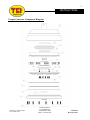
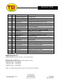
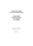
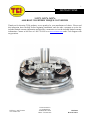
1
INSTRUCTIONS
242972, 242974, 242976
6L80 BOLT-TOGETHER TORQUE CONVERTER
Thank you for choosing TCI® products; we are proud to be your manufacturer of choice. Please read
this instruction sheet carefully before beginning installation, and also take a moment to review the
included limited warranty information and also take a moment to review the included limited warranty
information. Contact us toll free at 1.888.776.9824 or at www.tciauto.com under Tech Support with
any questions.
Toll Free: 1.888.776.9824
www.tciauto.com
TCI® Automotive
151 Industrial Dr.
Ashland, MS 38603
Phone: 662.224.8972
INST2429
Revised 7/18/13
2
INSTRUCTIONS
Torque Converter Component Diagram
Toll Free: 1.888.776.9824
www.tciauto.com
TCI® Automotive
151 Industrial Dr.
Ashland, MS 38603
Phone: 662.224.8972
INST2429
Revised 7/18/13
3
INSTRUCTIONS
ITEM QTY PART NUMBER
1
1 CMP2429-6LSTATOR
2
1 CMP2429-6LPUMP
3
1 CMP2429-6LTURBINE
4
2 BRNG-6807
5
1 CMP2429-5
6
3 CMP2429-9B
7
1 CMP2429-6LPISTON
8
1 CMP2429-8B
9
15 BLT1153
10
1 BUS435049
11
1 GSK-M264
12
2 CMP2429-WS
13
2 GSK-137
14
6 BLT1152
15
12 CMP2429-13
16
11 CMP12134
17
2 CMP2429-12
18
1 CH-2456L80
19
1 PNTSW-2-11
20
1 CVDB-W252-10113
21
3 BLT1154
22
3 TRIGM-RO-385
23
1 GSK33970
DESCRIPTION
STATOR, 6L80
PUMP, 6L80
TURBINE, 6L80
BEARING, DEEP GROOVE BALL 6807
FRONT
DOUBLE-SIDED FRICTION
PISTON ASSEMBLY
SINGLE-SIDED FRICTION
BOLT, 1/4-28 X 0.75" (FRONT TO PUMP)
BUSHING, CLUTCH HUB
PUMP TO FRONT O-RING
WAVE SPRING, BLEED OFF VALVE
TURBINE O-RING
BOLT, 1/4-28 X 0.5" (CLUTCH HUB TO PISTON)
SPRING SEAT
DAMPER SPRING
PRESSURE RELIEF VALVE
6L80 CLUTCH HUB, STREET
THRUST BEARING, THIN
THRUST BEARING, THICK
TORQUE CONVERTER BOLT
EXTRACTION PINS
INPUT SHAFT SEAL
REBUILD KIT P/N:
CMP2429-REB (includes bearings, seals, and frictions)
RE-STALL KIT P/N’S (includes pump and seals):
CMP2429-2800 – (2800 RPM)
CMP2429-3000 – (3000 RPM)
CMP2429-3200 – (3200 RPM)
Other re-stall kits offered upon request, call for pricing/availability
Toll Free: 1.888.776.9824
www.tciauto.com
TCI® Automotive
151 Industrial Dr.
Ashland, MS 38603
Phone: 662.224.8972
INST2429
Revised 7/18/13
4
INSTRUCTIONS
Installing Torque Converter:
Suggested accessories for install:
-TCI Max-Shift Synthetic ATF (950655 - single quart or 950650 - twelve quarts)
If only installing converter, you’ll need 5 quarts total
-TCI 6L80 Billet SFI 29.1 Flexplate (399757)
---Refer to factory service manual for torque converter removal and installation procedures.
The 6L80 transmission has a very specific fill procedure that must be followed precisely in order
to obtain proper fluid level (see next two pages). Improper fluid levels can cause transmission to
not function properly and can cause damage to both transmission and converter.
Keep the following in mind during the installation process:
-Fill converter with 2 quarts of TCI Max-Shift synthetic ATF prior to installing on transmission
-Replace input shaft o-ring (replacement o-ring included) and apply ample transmission fluid to
o-ring to lubricate for installation of converter.
-Once converter is installed into transmission, use a straight edge to measure from bellhousing
flange to converter bolt flange (surface that mates to flexplate). You should have a minimum
of 1.020” clearance with converter stabbed properly.
Bellhousing flange
1.020” MINIMUM
Converter bolt flange
Toll Free: 1.888.776.9824
www.tciauto.com
TCI® Automotive
151 Industrial Dr.
Ashland, MS 38603
Phone: 662.224.8972
INST2429
Revised 7/18/13
5
INSTRUCTIONS
Fill Procedure:
The 6L80 transmission fluid fill plug is located on the passenger side of the transmission and can be
removed by lifting the plunger in the fill plug. Use 90-degree needle nose or a flat head screwdriver to
pry plunger up in order to unlock fill plug. The fluid fill plug/plunger assembly can now be lifted out
of transmission case.
Lift on plunger here
This entire assembly lifts
out of transmission case
Fluid fill plug
With transmission out of car, place a funnel into the fluid fill hole. Pour three quarts of transmission
fluid into transmission. Replace plunger/plug assembly in transmission fluid fill hole.
The transmission is now ready to be reinstalled in the vehicle.
Once transmission is bolted to engine, torque the three converter to flexplate bolts (included in kit) to
40 ft-lbs.
Continue installation, following service manual procedures for the specific vehicle.
IMPORTANT---Refer to “Fluid Level Checking Procedure” (on next page) before driving
vehicle.
Toll Free: 1.888.776.9824
www.tciauto.com
TCI® Automotive
151 Industrial Dr.
Ashland, MS 38603
Phone: 662.224.8972
INST2429
Revised 7/18/13
6
INSTRUCTIONS
Fluid Level Checking Procedure:
Start the engine and allow it to idle.
Allow the fluid to reach operating temperature. The transmission fluid must be 86-122°F when
checking fluid level. Checking fluid outside this temperature range will result in inaccurate fluid
levels. Improper fluid levels can cause transmission to not function properly and damage to
transmission and converter can occur.
With engine still running and foot on the brake, put the shifter in each gear range. Pause for at least 3
seconds in each range. Put the shifter back in PARK. Once in PARK, verify that the engine RPM is
low (500-800 RPM). Let the vehicle idle for at least one minute.
With the vehicle level, engine idling, shifter in PARK you can now check the fluid level.
Important: VEHICLE MUST BE LEVEL WHEN CHECKING FLUID LEVEL
You are now ready to remove the plug bolt located on the transmission pan.
Important: THE ENGINE MUST BE RUNNING when the transmission pan plug bolt is removed.
The bolt is not a drain but rather the actual means of checking transmission fluid level. If engine is not
running, excessive fluid will drain from the transmission, resulting in an insufficient fluid level.
Transmission pan plug bolt
Remove the transmission pan plug bolt and allow any fluid to
drain out.
- If the fluid is flowing out, wait until the fluid slows to a drip.
- If no fluid comes out, add fluid until fluid begins to drip out.
Replace the transmission pan plug bolt and tighten to 18 ft-lbs.
Toll Free: 1.888.776.9824
www.tciauto.com
TCI® Automotive
151 Industrial Dr.
Ashland, MS 38603
Phone: 662.224.8972
INST2429
Revised 7/18/13
7
INSTRUCTIONS
Disassembling Torque Converter to change stall and service:
1. After removing converter from transmission, place converter in a pan with the hub pointed
down.
2. First remove the 15 1/4”-28 X 3/4” bolts from the front using a 3/16” allen wrench.
3. Next, insert the three extraction pins (included with kit) into the tapped converter bolt holes. Extraction pin
4. Take the converter to flexplate mounting bolts and thread them into the converter bolt holes.
Tighten them down in a progressive manner not exceeding 3 turns at a time. This will help the
front lift evenly and not bind. The converter bolts will push down on the inserted pins, lifting
the front away from the pump.
Toll Free: 1.888.776.9824
www.tciauto.com
TCI® Automotive
151 Industrial Dr.
Ashland, MS 38603
Phone: 662.224.8972
INST2429
Revised 7/18/13
8
INSTRUCTIONS
5. Next remove the front and set aside. You can now lift out the frictions and the piston, turbine,
stator, and bearings.
6. Now disassemble the clutch hub from the piston. Using a 3/16” hex key, remove the 6 1/4”-28
X 1/2” bolts from the clutch hub. The piston can now be removed.
7. The clutch hub contains two valves and springs. These can be removed and inspected.
8. The turbine has 11 damper springs located around its outer diameter. These springs have 2
spring-seats each and are simply pressed into the springs.
9. The bearing installed in the front can also be removed and inspected.
Toll Free: 1.888.776.9824
www.tciauto.com
TCI® Automotive
151 Industrial Dr.
Ashland, MS 38603
Phone: 662.224.8972
INST2429
Revised 7/18/13
9
INSTRUCTIONS
Assembling torque converter:
Rebuild kit p/n: CMP2429-REB
1. Inspect all parts for signs of wear or damage.
2. Inspect all seals for tears and other damage.
3. Install bearing into front. Bearing is sized to be a slip fit and should install easily by hand.
4. Once bearing is installed, place double-sided friction into front.
5. Next place single-sided friction into front. The single-sided must be placed on top of doublesided friction and must be placed with friction side up.
Toll Free: 1.888.776.9824
www.tciauto.com
TCI® Automotive
151 Industrial Dr.
Ashland, MS 38603
Phone: 662.224.8972
INST2429
Revised 7/18/13
10
INSTRUCTIONS
6. Next, the valves and springs will be installed into the clutch hub. First, check the condition of
the valve and bore. Confirm that there is no wear/galling/contamination that could cause the
valve to stick during operation. Proper orientation of the valve is critical. Once valves are
installed, wave springs can be installed on top of them.
PROPER VALVE ORIENTATION
7. Once valves and wave springs are installed, place piston on the clutch hub and install the six
1/4”-28 X 1/2” bolts, torquing them to 10 ft-lbs. each. (Note, piston drive teeth should be
opposite clutch hub)
Drive Teeth (this side)
Toll Free: 1.888.776.9824
www.tciauto.com
TCI® Automotive
151 Industrial Dr.
Ashland, MS 38603
Phone: 662.224.8972
INST2429
Revised 7/18/13
11
INSTRUCTIONS
8. The piston then can be placed on top of the frictions and into the front.
IMPORTANT: Special care must be taken to insure the piston drive teeth properly engage the
double sided friction. Failure to do so will cause converter to bind and will stall the vehicle
upon putting the transmission in gear.
Proper Tooth Engagement
9. Next, the damper springs need to be mated with their spring seats. Install two seats on each
spring (one on each end of spring).
10. Next, install the damper springs/seats into the spring retainers on the piston.
Toll Free: 1.888.776.9824
www.tciauto.com
TCI® Automotive
151 Industrial Dr.
Ashland, MS 38603
Phone: 662.224.8972
INST2429
Revised 7/18/13
12
INSTRUCTIONS
11. Next, the turbine-to-clutch hub o-ring needs to be installed on the turbine spline.
12. The turbine can now be installed onto the front and piston. The turbine must pilot into the
bearing in the front, as well as into the bushing on the clutch hub. Lubricant should be applied
to the o-ring to insure smooth installation without tearing (apply transmission fluid on by hand
to lubricate seal). The turbine spring retaining ring will hit the tops of each spring seat. Align
the spring pockets on the turbine with each spring and press down hard on turbine. The springs
will compress inwards slightly, allowing turbine to slide down around them. Please note, this
may take considerable effort, but they will align.
Toll Free: 1.888.776.9824
www.tciauto.com
TCI® Automotive
151 Industrial Dr.
Ashland, MS 38603
Phone: 662.224.8972
INST2429
Revised 7/18/13
13
INSTRUCTIONS
13. Next, the stator assembly can be installed. First place the larger diameter/thinner bearing onto
the turbine as depicted below. Then install stator and thick bearing as shown.
Note: Bearings must be installed and stator must be oriented as depicted
Larger diameter thinner bearing placed on turbine
(this side up)
Toll Free: 1.888.776.9824
www.tciauto.com
Stator placed on top of larger bearing and smaller diameter
thick bearing placed on top of stator (this side up)
TCI® Automotive
151 Industrial Dr.
Ashland, MS 38603
Phone: 662.224.8972
INST2429
Revised 7/18/13
14
INSTRUCTIONS
14. Next, install the pump-to-front o-ring in the o-ring groove on the front.
15. Lubricate this o-ring in the same manner as the turbine o-ring, using transmission fluid.
16. Note the alignment marks on pump and front. These marked holes must be aligned when
assembling front to pump.
IMPORTANT: The parts will only bolt together when these marks are aligned.
17. With the front, piston and table sitting on the table as depicted, align the marks on the pump
and the front while carefully lowering pump onto front and resting it on the o-ring.
Toll Free: 1.888.776.9824
www.tciauto.com
TCI® Automotive
151 Industrial Dr.
Ashland, MS 38603
Phone: 662.224.8972
INST2429
Revised 7/18/13
15
INSTRUCTIONS
18. Hanging the converter over the edge of the table will allow access to the bolt holes in the
converter. Slide a bolt through the front and begin threading bolt into pump. Just get the bolt
started (allowing 2-3 threads of engagement), do not tighten it yet. Rotate the converter 1/3 of
the way around and repeat with a second then third bolt. Once three bolts are started, begin
progressively tightening all three bolts, drawing the pump down over the o-ring. Do not tighten
any one bolt more than 3 turns at a time. Getting too far ahead with one bolt can cause the
pump to bind and can damage the parts.
.
19. With three bolts installed and the pump drawn down all the way, you can now flip the converter
over to access the remaining 12 bolts. Install all the 1/4-28 X 3/4” bolts and torque them to 10
ft-lbs. This completes the converter assembly process.
Social Media
Stay up-to-date with the latest TCI® and COMP Performance Group™ company and
product information by following us on any of our social media platforms.
Toll Free: 1.888.776.9824
www.tciauto.com
TCI® Automotive
151 Industrial Dr.
Ashland, MS 38603
Phone: 662.224.8972
INST2429
Revised 7/18/13
16
INSTRUCTIONS
Limited Warranty
TCI® Automotive warrants that all of its products are free from defects in material and workmanship
for a period of 1 year from the date of purchase. This limited warranty shall cover the original
purchaser.
TCI® Automotive’s obligation under this warranty is limited to the repair or replacement of its
product. To make a warranty claim, the part must be returned within 1 year of purchase to the address
listed below, freight prepaid. Items covered under warranty will be returned to you freight collect. It is
the responsibility of the installer to ensure that all of the components are correct before installation. We
assume no liability for any errors made in tolerances, component selection, or installation.
There is absolutely no warranty on the following:
•Any parts used in racing applications.
•Any product that has been physically altered, improperly installed or maintained.
•Any product used in improper applications, abused, or not used in conjunction with the proper
parts.
•Damage due to excessive manifold pressure, i.e. nitrous backfires, engine misfire, etc.
There are no implied warranties of merchantability or fitness for a particular purpose. There are
no warranties, which extend beyond the description of the face hereof. TCI® Automotive will not be
responsible for incidental and consequential damages, property damage or personal injury damages to
the extent permitted by law. Where required by law, implied warranties or merchantability and fitness
are limited to a term of 1 year from the date of original purchase.
This warranty gives you specific legal rights and you may also have other legal rights, which vary from
state to state.
Toll Free: 1.888.776.9824
www.tciauto.com
TCI® Automotive
151 Industrial Dr.
Ashland, MS 38603
Phone: 662.224.8972
INST2429
Revised 7/18/13