1
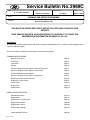
Service Bulletin No. 2969C
MODEL
TYPE
E / J Series Coaches
SUBJECT
SECTION/GROUP
Service Information
DATE
8-- Engine
April 13, 2009
CUMMINS ISM DIESEL EPA ENGINES
CONDITIONS
Service Information Only
THIS BULLETIN SUPERCEDES FIELD SERVICE BULLETIN 2969 & 2969B IN THEIR
ENTIRETY.
FIELD SERVICE BULLETIN 2969B WAS REVISED TO REVISION C TO UPDATE THE
REGENERATION INFORMATION ON PAGES 22, 23 & 25.
Description:
This service information bulletin will provide customer support documentation for E / J series coaches equipped with a
Cummins ISM EPA engine.
Service information contained in this bulletin covers the following items:
CUMMINS ISM EPA ENGINE
General Description
Page 2
ULSD Fuel
Page 2
Lubrication
Page 2
Coolant
Page 3
Electronic Engine Control System / General Description
Page 4
Electronic Engine Control System / Components
Page 4
Preventive Maintenance Schedule
Page 5
Electronic Engine Control System / Diagnostics
Page 5
Diagnostic Trouble Codes Retrieval
Page 6
Diagnostic Trouble Codes
Page 9
Torque Chart
Page 17
Engine Data
Page 17
Specifications
Page 18
DIESEL PARTICULATE FILTER
General Description
Page 19
Regeneration
Page 21
Regeneration Tell-tale Lamps
Page 21
Regeneration Modes
Page 22
Regeneration Switch
Page 22
Regeneration Strategy
Page 25
Check Message Tell-tale
Page 24
Printed in Canada
Service Bulletin No. 2969C
DATE APR. 13, 2009 PAGE
2
CUMMINS DIESEL ISM ENGINE
GENERAL DESCRIPTION
The Cummins Diesel ISM engine is a six-cylinder, four-stroke, right-hand rotation, high speed, high torque diesel engine
with exhaust gas recirculation ( EGR ). This engine is turbocharged, intercooled and electronically controlled by the
engine control module ( ECM ).
COOLANT TEMPERATURE OPERATING RANGE
NORMAL OPERATING RANGE
190_F---205_F ( 87_C---96_C )
AMBER CHECK ENGINE TELLTALE LAMP ILLUMINATES
216_F ( 102_C )
RED STOP ENGINE TELLTALE LAMP ILLUMINATES
226_F ( 108_C )
WATER TEMPERATURE GAUGE RED LED LIGHT ILLUMINATES
227_F ( 108_C )
ENGINE THERMOSTAT STARTS TO OPEN
180_F ( 82_C )
ENGINE THERMOSTAT FULLY OPEN
201_F ( 94_C )
DIESEL FUEL
NOTE
Effective with unit number 64455 ( as well as 63876, 64301, 64302, 64342, 64343, 64371, 64372 and
64402 ) engines must must comply with EPA mandated low emission guidelines by using ULSD ( ultra
low sulfur diesel ) fuel. Refer to MCI Service Bulletin 2947, located at www.mcicoach.com, for more
information regarding ULSD.
Failure to use ULSD fuel in 2007 EPA engines will result in component damage.
LUBRICATION
Diesel Engine Lubricating Oils
Cummins Diesel ISM engines have an oil capacity of 36 U.S. qts.
Diesel engines require heavy-duty lubricating oils. Basic requirements of such oils are lubricating quality, high heat
resistance, and control of contaminants. The only lubricating oil recommended for ISM diesel engines is the CES 20071 or
CES 20076 and viscosity grade SAE 15W-40.
Synthetic Oils
Synthetic oils may be used in Cummins engines, provided they are API licensed and meet the performance and
chemical requirements of non---synthetic oils in the API Category III and viscosity grade SAE 15W-40. The use of synthetic
oil does not extend the oil drain interval recommended by Cummins.
Table 1. Lubricating Oil Recommended
API Service Code
Classification
SAE
Grade
CJ--4
15W--40 Summer / 5W--40 Winter
Effective with unit number 64455 ( as well as 63876, 64301, 64302, 64342, 64343, 64371, 64372 and 64402 ),
2007 EPA engines must only use CJ- 4 engine oil. If the ambient temperature is above 15_F (- 9.5_C), 15W40
oil must be used. If the ambient temperature is below 15_F (- 9.5_C), 5W40 must be used.
Failure to use CJ- 4 engine oil in 2007 EPA engines will reduce component life.
Printed in Canada
Service Bulletin No. 2969C
DATE APR. 13, 2009 PAGE
3
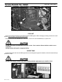
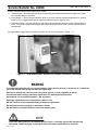
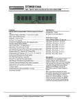
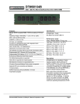
Figure 1. Cummins ISM engine oil fill and dipstick location.
COOLANT
Power Cool or Power Cool Plus can be used in Cummins ISM engines. Before changing or adding coolant to the coach
system, verify the type of coolant used in the coach.
Power Cool Plus can be identified by it’s red color. Power Cool can be identified by it’s purple color.
DO NOT mix Power Cool and Power Cool Plus coolant. Each contains different inhibitors which are not
compatible.
Mixing coolants will result in component failure.
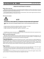
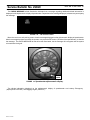
SURGE TANK
Coaches equipped with Cummins ISM engines have a new designed surge tank installation, with an increased rad cap
pressure of 15 psi.
DO NOT interchange a radiator cap without verifying that the replacement cap is rated for 15 psi.
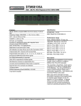
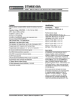
Figure 2. Radiator cap location.
Printed in Canada
Service Bulletin No. 2969C
DATE APR. 13, 2009 PAGE
4
ELECTRONIC ENGINE CONTROL SYSTEM
GENERAL DESCRIPTION
The electric engine control system receives, processes and stores information from sensors located throughout the
engine and related components.
The electronic engine control system has protection circuits that reduce power and shut the engine down under
potentially damaging conditions, such as low oil pressure, low coolant level or high engine temperature.
The electronic engine control system is self---diagnostic, and warns the operator of fault conditions and potential
problems by lighting telltales. Fault codes that identify failed components are logged into the system’s ECM memory for
readout by maintenance personnel.
COMPONENTS
Electronic Control Module (ECM)
The electronic control module is the microprocessor-controlled electronic monitoring and storage unit for the engine
control system.
The ECM can identify problem conditions within the engine by comparing input from the various sensors to a set of
parameters (calibration and design data) stored within the ECM. After processing the input, the ECM sends high current
command pulses to the injector solenoids to initiate fuel injection. The ECM also receives feedback regarding the start
and end of injection for a given cylinder.
NOTE:
There are no user-serviceable parts within the ECM.
The ECM is factory programmed for a specific engine/transmission/tire size and axle ratio combination.
Electronic Unit Injectors (EUI)
Electronic unit injectors are electronically---controlled fuel injectors. They are mounted into the cylinder heads above
each cylinder. The solenoid---operated poppet valve on each EUI performs injection timing and fuel metering functions
Throttle Position Sensor (TPS)
The throttle position sensor is located in the electronic foot pedal assembly. The TPS converts the throttle position into
a signal for the ECM.
Turbocharged Boost Sensor (TBS)
The turbocharged boost sensor is located between the turbocharger discharge waste gate and the blower. The TBS
monitors turbocharger compressor discharge pressure.
Oil Pressure Sensor (OPS)
The oil pressure sensor is located at the rear RH side of the engine block. The OPS monitors oil pressure in the engine.
If engine oil pressure falls below the specified minimum, the ECM lights the CHECK ENGINE and/or STOP ENGINE
telltales. The ECM initiates the engine protection shutdown sequence.
Oil Temperature Sensor (OTS)
The oil temperature sensor is located in the engine oil gallery at rear RH side of the engine block.
Coolant Temperature Sensor (CTS)
The coolant temperature sensor is mounted in the engine thermostat housing.
Coolant Level Sensor (CLS)
The coolant level sensor is a two piece assembly made up of a sensor probe and module. The sensor is located near
the bottom of the radiator’s surge tank, and monitors the coolant level.
Air Temperature Sensor (ATS)
The air temperature sensor monitors intake manifold air temperature to use for charge-air clutch fan control.
Printed in Canada
Service Bulletin No. 2969C
DATE APR. 13, 2009 PAGE
5
PREVENTIVE MAINTENANCE SCHEDULE
Engine Service Intervals
Generally, the service intervals given in the Cummins ISM Service Manual are minimum requirements to keep the
engine warranty valid. When determining maintenance schedules, more frequent service intervals should be considered
for operating conditions that are harsher than normal.
Lube oil sample analysis at regular drain intervals is recommended to detect internal engine malfunctions before a
costly catastrophic failure and a “coach down” occurs.
Filter Service Intervals
NOTE
Local conditions, severity of operation, or duty cycle may require more frequent fluid change intervals
that differ from the recommended Cummins ISM Operation and Maint. Manual fluid change intervals.
Change fluid / filters after recommended mileage, months, or hours have elapsed, whichever occurs
first.
Change lubricating oil and filter every 6000 miles, 9600 km, 500 hours or 3 months.
Change fuel filter every 6000 miles, 9600 km, 500 hours or 3 months.
Change coolant filter every 150,000 miles, 240,000 km, 4000 hours or 1 year.
DIAGNOSTICS
The ISM electronic engine control system’s diagnostics feature can be separated into three areas: engine performance
diagnostics, self-diagnostics and engine protection.
Engine Performance Diagnostics
The system continuously monitors sensors and makes adjustments to the injector timing and fuel quantity input. This
provides optimum performance and minimal acceleration smoke under all operating conditions. Cold weather starting is
improved by matching the fuel input and timing to the ambient air temperature.
System Self-Diagnostics
The system continually monitors itself and all related wiring for faults. If a fault is detected, the CHECK ENGINE and/or
STOP ENGINE telltales light. If the fault is in the main microprocessor, a backup microprocessor takes control. When the
system is under the control of the backup microprocessor, the engine continues to work normally. A generic set of
calibration data is substituted, which may degrade engine performance. Auxiliary features that remain operational during
backup mode are the engine protection feature and accessory equipment pulse width modulation.
Engine Protection
When the engine protection feature is initiated, the check engine and stop engine telltales light. A fault code is logged
into the ECM’s memory and the engine is rapidly derated until it shuts down after 30 seconds.
The operator can delay shutdown for 30 seconds by pressing the override switch. The override can be activated as
often as required.
If the fault was temporary, the telltales go out and normal operation resumes. A fault code is logged in memory until the
memory is cleared. The memory can be cleared with a diagnostic data reader.
Printed in Canada
Service Bulletin No. 2969C
DATE APR. 13, 2009 PAGE
6
DIAGNOSTIC TROUBLE CODE RETRIEVAL
NOTE
Effective with unit number 64455 ( as well as 63876, 64301, 64302, 64342, 64343, 64371, 64372 and 64402 ),
engine diagnostic trouble codes are indicated through the alphanumeric display, located at the bottom of
the speedometer.
The yellow Check Engine and red Stop Engine tell-tale lights no longer indicate engine codes.
Engine Code Retrieval
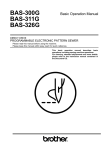
The alphanumeric display, located at the bottom of the speedometer, displays the diagnostic trouble codes
( Figure 3 ).
The diagnostic trouble codes are displayed as J1939 SPN---FMI codes. A maximum of five codes can be listed at one
time. These codes are logged in the ECM with the most severe or recent code listed first.
The MODE switch allows the driver to scroll through active system messages, when the coach is at a complete stop.
Pressing the SET switch will not clear the diagnostic trouble codes.
Record all codes.
Engine Code Example:
Source Code: 0 ( Engine )
P (SPN):
27
FMI:
4
27 (4) -- EGR Valve Position Circuit / Voltage Below Normal or Shorted to Low Source
NOTE
MCI has designated Source Code “ 0 “ for the engine codes.
MODE
button
SET
button
FIGURE 3. Speedometer alphanumeric display.
Printed in Canada
Service Bulletin No. 2969C
DATE APR. 13, 2009 PAGE
7
Engine Code Retrieval cont’d
To navigate to the FAULTS screen on the speedometer alphanumeric display:
--- press the MODE button ( LH side of the speedometer ) 5 times, to display the DIAGNOSTIC screen (Figure 4),
FIGURE 4. Speedometer ( Diag. screen )
--- press the SET button ( RH side of the speedometer ) 1 time, to display the AUTO screen (Figure 5),
FIGURE 5. Speedometer
--- press the MODE button ( LH side of the speedometer ) 2 times, to display the FAULTS screen (Figure 6),
FIGURE 6. Speedometer ( Faults screen )
Printed in Canada
Service Bulletin No. 2969C
Engine Code Retrieval cont’d
DATE APR. 13, 2009 PAGE
--- press the SET button 1 time, to display the Parameter Group Number ( PGN ) / “ code ” screen (Figure 7),
FIGURE 7. Speedometer ( PGN screen )
--- press the SET button 1 time, to display the SPN / Source screen,
FIGURE 8. Speedo (Source code {SRC})
NOTE
MCI has designated Source Code “ 0 “ for the engine codes.
--- press the SET button 1 time, to display the FMI screen (Figure 9).
FIGURE 9. Speedometer ( FMI ).
FIGURE 10. Speedometer ( No codes present ).
Printed in Canada
8
Service Bulletin No. 2969C
DATE APR. 13, 2009 PAGE
9
CUMMINS ISM DIAGNOSTIC TROUBLE CODES
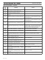
Fault Code Information
J1939
P(SPN)
(FMI)
REASON
EFFECT
27
(4)
EGR Valve Position Circuit -- Voltage Below Normal or Shorted to Low Source.
EGR valve actuation will be disabled.
31
(0)
Exhaust Gas Circulation (EGR) System -- Condition Exists.
EGR valve operation will be disabled.
81
(16)
Engine Particulate Trap Inlet Pressure -- Data Valid None on performance.
but Above Normal Operational Range -- Moderately
Severe Level.
84
(2)
Wheel Based Vehicle Speed -- Data Erratic, Intermittent or Incorrect.
Engine speed limited Maximum Engine Speed
without VSS parameter value. Cruise control,
Geardown Protection, and Road Speed Governor
will not work.
84
(10)
Wheel Based Vehicle Speed Sensor Circuit Tampering has been Detected.
Engine speed limited Maximum Engine Speed
without VSS parameter value. Cruise control,
Geardown Protection, and Road Speed Governor
will not work.
91
(3)
Accelerator Pedal or Lever Position Sensor1 Circuit -- Voltage Below Normal or Shorted to High
Source.
Severe derate in power output of the engine. Limp
home power only.
91
(4)
Accelerator Pedal or Lever Position Sensor 1 Circuit -- Voltage Above Normal or Shorted to Low
Source.
Severe derate in power output of the engine. Limp
home power only.
91
(2)
Accelerator Pedal or Lever Position Sensor 1 and
2 -- Data Erratic, Intermittent, or Incorrect.
The engine will only idle.
91
(19)
SAE J1939 Multiplexed Accelerator Pedal or Lever
Sensor System -- Received Network Data in Error.
Engine may only idle or engine will not accelerate
to full speed.
97
(15)
Water In Fuel Indicator -- Data Valid but Below Nor- Possible white smoke, loss of power, or hard startmal Operational Range -- Least Severe Level.
ing.
97
(3)
Water in Fuel Indicator Sensor Circuit -- Voltage
Above Normal or Shorted to High Source.
None on performance. No water in fuel warning
available.
97
(4)
Water in Fuel Indicator Sensor Circuit -- Voltage
Below Normal or Shorted to Low Source.
None on performance. No water in fuel warning
available.
100
(3)
Engine Oil Riffle Pressure 1 Sensor Circuit -- Voltage Above Normal or Shorted to High Source.
None on performance. No engine protection for oil
pressure.
100
(4)
Engine Oil Riffle Pressure 1 Sensor Circuit -- Voltage Below Normal or Shorted to Low Source
None on performance. No engine protection for oil
pressure.
100
(18)
Engine Oil Riffle Pressure -- Data Valid but Below
Normal Operational Range -- Moderately Severe
Level.
Progressive power derate increasing in severity
from time of alert.
100
(1)
Engine Oil Riffle Pressure -- Data Valid but Below
Normal Operational Range -- Most Severe Level.
Progressive power derate increasing in severity
from time of alert. If Engine Protection Shutdown
feature is enabled, engine will shut down 30 seconds after red STOP lamp starts flashing.
Printed in Canada
Service Bulletin No. 2969C
DATE APR. 13, 2009 PAGE
10
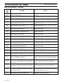
Fault Code Information -- Continued.
J1939
SPN
(FMI)
REASON
EFFECT
100
(2)
Engine Oil Riffle Pressure -- Data Erratic, Intermittent, or Incorrect.
101
(16)
Crankcase Pressure -- Data Valid but Above NorNone on performance.
mal Operational Range -- Moderately Severe Level.
101
(0)
Crankcase Pressure -- Data Valid but Above Normal Operation Range -- Most Severe Level.
Engine power derate.
101
(3)
Crankcase Pressure Circuit -- Voltage Above Normal or Shorted to High Source.
No engine protection for high crankcase pressure.
101
(4)
Crankcase Pressure Circuit -- Voltage Below Normal or Shorted to Low Source.
No engine protection for high crankcase pressure.
101
(2)
Crankcase Pressure -- Data Erratic, Intermittent or
Incorrect.
None on performance.
101
(15)
Crankcase Pressure -- Data Valid but Above Normal Operational Range -- Least Severe Level.
None on performance.
102
(3)
Intake Manifold 1 Pressure Sensor Circuit -- Voltage Above Normal or Shorted to High Source.
Derate in power output of the engine.
102
(4)
Intake Manifold 1 Pressure Sensor Circuit -- Voltage Below Normal or Shorted to Low Source.
Derate in power output of the engine.
102
(2)
Intake Manifold 1 Pressure -- Data Erratic, intermit- Engine power derate.
tent, or Incorrect.
103
(15)
Turbocharger 1 Speed -- Data Valid but Above Nor- Engine power derate to lower the turbocharger
mal Operational Range -- Least Severe Level.
speed.
103
(10)
Turbocharger 1 Speed -- Abnormal Rate of
Change.
None on performance. The ECM uses and estimated turbocharger speed.
103
(2)
Turbocharger 1 Speed -- Data Erratic, Intermittent,
or Incorrect.
None on performance. The ECM uses an estimated turbocharger speed.
103
(18)
Turbocharger 1 Speed -- Data Valid but Below Nor- Engine power derate. The ECM uses an estimated
mal Operational Range -- Moderately Severe Level. turbocharger speed.
105
(3)
Intake Manifold 1 Temperature Sensor Circuit -Voltage Above Normal or Shorted to High Source.
Possible white smoke. Fan will stay ON if controlled by ECM. No engine protection for engine
coolant temperature.
105
(4)
Intake Manifold 1 Temperature Sensor Circuit -Voltage Below Normal or Shorted to Low Source.
Possible white smoke. Fan will stay ON if controlled by ECM. No engine protection for engine
coolant temperature.
105
(15)
Intake Manifold 1 Temperature -- Data Valid but
Above Normal Operational Range -- Least Severe
Level.
Progressive power derate increasing in severity
from time of alert.
105
(0)
Intake Manifold 1 Temperature -- Data Valid but
Above Normal Operational Range -- Most Severe
Level.
Progressive power derate increasing in severity
from time of alert. If Engine Protection Shutdown
feature is enabled, engine will shut down 30 seconds after red STOP lamp starts flashing.
Printed in Canada
None on performance. No engine protection for oil
pressure.
Service Bulletin No. 2969C
DATE APR. 13, 2009 PAGE
11
Fault Code Information -- Continued.
J1939
SPN
(FMI)
REASON
EFFECT
108
(3)
Barometric Pressure Sensor Circuit -- Voltage
Above Normal or Shorted to High Source.
Engine power derate.
108
(4)
Barometric Pressure Sensor Circuit -- Voltage Below Normal or Shorted to Low Source.
Engine power derate
108
(2)
Barometric Pressure -- Data Erratic, Intermittent, or Engine power derate.
Incorrect.
110
(3)
Engine Coolant Temperature 1 Sensor Circuit -Voltage Above Normal or Shorted to High Source.
Possible white smoke. Fan will stay ON if controlled by ECM. No engine protection for engine
coolant temperature.
110
(4)
Engine Coolant Temperature 1 Sensor Circuit -Voltage Below Normal or Shorted to Low Source.
Possible white smoke. Fan will stay ON if controlled by ECM. No engine protection for engine
coolant temperature.
110
(16)
Engine Oil Riffle Pressure -- Data Valid but Above
Normal Operational Range -- Moderately Severe
Level.
Power derate and possible engine shutdown. If
Engine Protection Shutdown feature is enabled.
110
(0)
Engine Coolant Temperature -- Data Valid but
Above Normal Operational Range -- Mose Severe
Level.
Progressive power derate increasing in severity
from time of alert. If Engine Protection Shutdown
feature is enabled, engine will shut down 30 seconds after red STOP lamp starts flashing.
110
(31)
Engine Coolant Temperature -- Conditions Exists.
EGR valve actuation will be disabled.
110
(31)
Engine Coolant Temperature -- Condition Exists.
EGR valve actuation will be disabled.
110
(15)
Engine Coolant Temperature -- Data Valid but
Above Normal Operational Range -- Least Severe
Level.
Power derate and possible engine shutdown if engine protection shutdown feature is enabled.
111
(3)
Coolant Level Sensor 1 Circuit -- Voltage Above
Normal or Shorted to High Source.
None on performance.
111
(4)
Coolant Level Sensor 1 Circuit -- Voltage Below
Normal or Shorted to Low Source.
None on performance.
111
(18)
Coolant Level -- Data Valid but Below Normal Operational Range -- Moderately Sever Level.
None on performance.
111
(17)
Coolant Level -- Data Valid but Below Normal Operational Range -- Least Severe Level.
None on performance.
167
(16)
Electrical Charging System Voltage -- Data Valid
Amber warning lamp illuminated until high battery
but Above Normal Operational Range -- Moderately voltage condition is corrected.
Severe Level.
167
(18)
Electrical Charging System Voltage -- Data Valid
Amber lamp will light until low battery voltage conbut Below Normal Operational Range -- Moderate- dition is corrected.
ly Severe Level.
167
(1)
Electrical Charging System Voltage -- Data Valid
but Below Normal Operational Range -- Most Severe Level.
Red lamp illuminated until very low battery voltage
condition is corrected.
168
(18)
Battery 1 Voltage -- Data Valid but Below Normal
Operational Range -- Moderately Severe Range.
Engine may stop running or be difficult to start.
Printed in Canada
Service Bulletin No. 2969C
DATE APR. 13, 2009 PAGE
12
Fault Code Information -- Continued.
J1939
SPN
(FMI)
REASON
EFFECT
168
(16)
Battery 1 Voltage -- Data Valid but Above Normal
Operational Range -- Moderately Severe Level.
Possible electrical damage to all electrical components.
171
(3)
Ambient Air Temperature Sensor 1 Circuit -- Voltage Above Normal or Shorted to High Source.
None on performance.
171
(4)
Ambient Air Temperature Sensor 1 Circuit -- Voltage Below Normal or Shorted to Low Source.
None on Performance.
175
(0)
Engine Oil Temperature High -- Data Valid but
Above Normal Operational Range -- Most Severe
Level.
Progressive power derate increasing in severity
from time of alert. If Engine Protection Shutdown
feature is enabled, engine will shut down 30 seconds after red STOP lamp starts flashing.
175
(3)
Engine Oil Temperature Sensor 1 Circuit Voltage
Above Normal or Shorted to High Source.
No engine protection for engine oil temperature.
175
(4)
Engine Oil Temperature Sensor 1 Circuit Voltage
Below Normal or Shorted to Low Source.
No engine protection for engine oil temperature.
190
(0)
Engine Crankshaft Speed/Position -- Data Valid but Fuel injection disabled until engine speed falls beAbove Normal Operational Range -- Most Severe
low the overspeed limit.
Level.
190
(2)
Engine Crankshaft Speed/Position -- Data Erratic,
Intermittent, or Incorrect.
Engine can run rough. Possibly poor starting capability. engine runs using backup speed sensor.
engine power is reduced.
251
(2)
Real--Time Clock Power Interrupt -- Data Erratic,
Intermittent, or Incorrect.
None on performance. Data in the ECM will not
have accurate time and date information.
411
(2)
Exhaust Gas Recirculation Valve Delta Pressure -Data erratic, Intermittent or Incorrect.
EGR valve actuation will be disabled.
411
(3)
Exhaust Gas Recirculation Valve Delta Pressure
Sensor Circuit -- Voltage Above Normal or Shorted
to High Source
EGR valve actuation will be disabled.
411
(4)
Exhaust Gas Recirculation Valve Delta Pressure
Sensor Circuit -- Voltage Below Normal or Shorted
to Low Source
EGR valve actuation will be disabled.
411
(16)
Exhaust Gas Recirculation Valve Delta Pressure -Data Valid but Above Normal Operational Range -Moderately Severe Level.
EGR valve actuation will be disabled.
411
(18)
Exhaust Gas Recirculation Valve Delta Pressure -Data Valid but Above Normal Operational Range -Moderately Severe Level.
EGR valve operation will be disabled.
412
(3)
Exhaust Gas Recirculation Temperature Sensor
Circuit -- Voltage Above Normal or Shorted to High
Source.
EGR valve actuation will be disabled.
412
(4)
Exhaust Gas Recirculation Temperature Sensor
Circuit -- Voltage Below Normal or Shorted to Low
Source.
EGR valve actuation will be disabled.
412
(15)
Exhaust Gas Recirculation Temperature -- Data
Slight fueling derate to bring EGR temperature unValid but Above Normal Operational Range -- Least der the maximum limit.
Severe Level.
Printed in Canada
Service Bulletin No. 2969C
DATE APR. 13, 2009 PAGE
13
Fault Code Information -- Continued.
J1939
SPN
(FMI)
REASON
EFFECT
412
(16)
Exhaust Gas Recirculation Temperature -- Data
Valid but Above Normal Operational Range -- Moderately Severe Level.
Severe fueling derate to bring EGR temperature
under the maximum limit.
612
(2)
Engine Magnetic Speed/Position Lost Both of Two
-- Data Erratic, Intermittent, or Incorrect.
None on performance.
626
(3)
Start Enable Device 1 Circuit (Ether Injection) -Voltage Above Normal or Shorted to High Source.
Ether start functionality will be disabled.
626
(4)
Start Enable Device 1 Circuit (Ether Injection) -Voltage Below Normal or Shorted to Low Source.
Ether start functionality will be disabled.
627
(12)
Injector Power Supply -- Bad Intelligent Device or
Component.
Possible low power, engine misfire, and/or engine
will not start.
627
(2)
Power Supply Lost With Ignition On -- Data Erratic,
Intermittent, or Incorrect.
Possible no noticeable performance effects or engine dying or hard starting. Fault information, trip
information, and maintenance monitor data can be
inaccurate.
629
(12)
Electronic Control Module Critical Internal Failure-Bad Intelligent Device or Component.
Engine may not start.
632
(4)
Engine Fuel Shutoff Valve Driver Circuit-- Voltage
Below Normal or Shorted to Low Source.
Fuel shutoff valve will close. Engine will shutdown.
632
(3)
Engine Fuel Shutoff Valve Driver Circuit-- Voltage
Above Normal or Shorted to High Source.
Fuel shutoff valve may not open when keyswitch is
in ON position, or may not close when keyswitch is
in OFF position.
639
(9)
SAE J1939 Multiplexing PGN Timeout Error Abnor- One or more multiplexed devices will not operate
mal Update Rate.
properly. One or more symptoms will occur.
639
(13)
SAE J1939 Multiplexing Configuration Error -- Out
of Calibration.
At least one multiplexed device will not operate
properly.
639
(9)
J1939 Datalink -- Abnormal Update Rate.
Engine speed will ramp down and remain at idle.
641
(15)
VGT Actuator Driver Over Temperature (Calculated) -- Data Valid but Above Normal Operational
Range -- Least Severe Level.
None on performance.
641
(11)
VGT Actuator Driver Circuit -- Root Cause Not
Known
VGT actuation will be disabled.
641
(7)
VGT Actuator Driver Circuit (Motor) -- Mechanical
System Not Responding Properly or Out of Adjustment.
VGT travel may be limited.
641
(12)
VGT Actuator Controller -- Bad Intelligent Device or VGT actuation will be disabled.
Component.
641
(31)
VGT Actuator Driver Circuit -- Condition Exists.
VGT actuation will be disabled.
641
(9)
VGT Actuator Driver Circuit -- Abnormal Update
Rate.
Active aftertreatment diesel particulate filter regeneration will be disabled.
641
(13)
VGT Actuator Controller -- Out of Calibration.
Low intake manifold pressure.
Printed in Canada
Service Bulletin No. 2969C
DATE APR. 13, 2009 PAGE
14
Fault Code Information -- Continued.
J1939
SPN
(FMI)
REASON
EFFECT
647
(4)
Fan Control Circuit -- Voltage Below Normal or
Shorted to Low Source.
The fan can possibly stay on continuously or not
run at all.
647
(3)
Fan Control Circuit -- Voltage Above Normal or
Shorted to High Source.
The fan may stay on continuously or not run at all.
651
(6)
Injector Solenoid Driver Cylinder 1 Circuit -- Current Current to injector is shut off. Engine can possible
Above Normal or Grounded Circuit.
misfire or run rough.
651
(5)
Injector Solenoid Driver Cylinder 1 Circuit -- Current Current to injector is shut off. Engine can possibly
Below Normal or Open Circuit.
misfire or run rough.
653
(6)
Injector Solenoid Driver Cylinder 3 Circuit -- Current Current to injector is shut off. Engine can possible
Above Normal or Ground Circuit.
misfire or run rough.
653
(5)
Injector Solenoid Driver Cylinder 3 Circuit -- Current Current to injector is shut off. Engine can possibly
Below Normal or Open Circuit.
misfire or run rough.
654
(6)
Injector Solenoid Cylinder Number 4 Circuit -- Current Above Normal or Grounded Circuit.
654
(5)
Injector Solenoid Driver Cylinder 4 Circuit -- Current Current to injector is shut off. Engine can possibly
Below Normal or Open Circuit.
misfire or run rough.
655
(6)
Injector Solenoid Driver Cylinder 5 Circuit -- Current Current to injector is shut off. Engine can possible
Above Normal or Grounded Circuit.
misfire or run rough.
655
(5)
Injector Solenoid Drive Cylinder 5 Circuit -- Current
Below Normal or Open Circuit.
656
(5)
Injector Solenoid Driver Cylinder 6 Circuit -- Current Current to injector is shut off. Engine can possibly
Below Normal or Open Circuit
misfire or run rough.
656
(6)
Injector Solenoid Driver Cylinder 6 Circuit -- Current Current to injector is shut off. Engine can possible
Above Normal or Grounded Circuit.
misfire or run rough.
662
(6)
Injector Solenoid Driver Cylinder 2 Circuit -- Current Current to injector is shut off. Engine can possible
Above Normal or Grounded Circuit.
misfire or run rough.
677
(3)
Starter Relay Driver Circuit -- Voltage Above Normal or Shorted to High Source.
Either the engine will not start or the engine will not
have starter lockout protection.
677
(4)
Starter Relay Driver Circuit -- Voltage Below Normal or Shorted to Low Source.
The engine will not have starter lockout protection.
723
(2)
Engine Camshaft Speed/Position Sensor -- Data
Erratic, Intermittent, or Incorrect.
Engine can run rough. Possible poor starting capability. Engine runs using primary engine position
sensor.
974
(3)
Remote Accelerator Pedal or Lever Position SenRemote accelerator will not operate. Remote acsor 1 Circuit -- Voltage Above Normal or Shorted to celerator position will be set to zero percent.
High Source.
974
(4)
Remote Accelerator Pedal or Lever Position Sensor1 Circuit -- Voltage Below Normal or Shorted to
Low Source.
Remote accelerator will not operate. Remote accelerator position will be set at zero percent.
974
(19)
SAE J 1939 Multiplexing Remote Accelerator Pedal or Lever Position Sensor System -- Received
Network Data in Error.
The engine will not respond to the remote throttle.
Engine may only idle. The primary or cab accelerator may be able to be used.
1072
(3)
Engine Brakes Actuator Driver 1 Circuit -- Voltage
Above Normal or Shorted to High Source.
Engine brake on cylinders 1, 2, and 3 can be on all
the time or can not be activated.
Printed in Canada
Current to injector is shut off. Engine can possibly
misfire or run rough.
Current to injector is shut off. Engine can possibly
misfire or run rough.
Service Bulletin No. 2969C
DATE APR. 13, 2009 PAGE
15
Fault Code Information -- Continued.
J1939
SPN
(FMI)
REASON
EFFECT
1072
(4)
Engine Brakes Actuator Driver 1 Circuit -- Voltage
Above Below or Shorted to Low Source.
Engine brake on cylinders 1, 2, and 3 can not be
activated.
1073
(4)
Engine Brake Actuator Driver Output 2 Circuit -Voltage Below Normal or Shorted to Low Source.
Engine brakes on cylinders Number 4, 5, and 6
can not be activated.
1073
(3)
Engine Brake Actuator Driver Output 2 Circuit -Voltage Above Normal or Shorted to High Source.
Engine brakes on cylinders Number 4, 5, and 6
can not be deactivated, or can not be activated.
1136
(3)
ECM Internal Temperature Sensor Circuit -- Voltage Above Normal or Shorted to High Source.
None on performance.
1136
(4)
ECM Internal Temperature Sensor Circuit -- Voltage Below Normal or Shorted to Low Source.
None on performance.
1172
(3)
Turbocharger 1 Compressor Inlet Temperature
Sensor Circuit -- Voltage Above Normal.
Engine power derate.
1172
(4)
Turbocharger 1 Compressor Inlet Temperature
Sensor Circuit -- Voltage Below Normal, or Shorted
to Low Source.
Engine power derate.
1209
(3)
Exhaust Gas Pressure Sensor Circuit -- Voltage
Above Normal or Shorted to Low Source.
None on performance.
1209
(4)
Exhaust Gas Pressure Sensor Circuit -- Voltage
Below Normal or Shorted to Low Source.
None on performance.
1209
(2)
Exhaust Gas Pressure -- Data Erratic, Intermittent,
or Incorrect.
The ECM will estimate the exhaust gas pressure.
1209
(16)
Exhaust Gas Pressure -- Data Valid but Above Nor- Fueling derate to bring exhaust gas pressure below
mal Operational Range -- Moderately Severe Level. the maximum operating limits.
1267
(3)
Idle Shutdown Vehicle Accessories Relay Driver
Circuit -- Voltage Above Normal or Shorted to High
Source.
Vehicle accessories or ignition bus loads controlled
by the idle shutdown relay will not power up.
1267
(4)
Idle Shutdown Vehicle Accessories Relay Driver
Circuit -- Voltage Below Normal or Shorted to Low
Source.
Vehicle accessories or ignition bus loads controlled
by the idle shutdown relay will not power up.
1378
(31)
Engine Oil Change Interval -- Condition Exists.
Maintenance reminder only.
1590
(2)
Adaptive Cruise Control Mode -- Data Erratic, Inter- Adaptive cruise control will not operate. Standard
mittent, or Incorrect.
cruise control may not operate
1639
(2)
Fan Speed -- Data Erratic, Intermittent, or Incorrect.
The fan will only be in the ON or OFF position.
2623
(3)
Accelerator Pedal or Lever Position Sensor 2 Circuit -- Voltage Above Normal or Shorted to High
Source.
Severe derate in power output of the engine. Limp
home power only.
2623
(4)
Accelerator Pedal or Lever Position Sensor 2 Circuit -- Voltage Below Normal or Shorted to Low
Source.
Severe derate in power output of the engine. Limp
home power only.
2789
(15)
Turbocharger Turbine Inlet Temperature (Calculated) -- Data Valid but Above Normal Operational
Range -- Least Severe Level.
Fuel is limited in an attempt to decrease the exhaust gas temperature entering the turbocharger.
Printed in Canada
Service Bulletin No. 2969C
DATE APR. 13, 2009 PAGE
16
Fault Code Information -- Continued.
J1939
SPN
(FMI)
REASON
EFFECT
2790
(15)
Turbocharger Compressor Outlet Temperature
Fuel is limited in an attempt to decrease the ex(Calculated) -- Data Valid but Above Normal Opera- haust gas temperature entering the turbocharger.
tional Range -- Least Severe Level.
2791
(12)
EGR Valve Controller -- Bad Intelligent Device or
Component.
EGR valve operation will be disabled.
2791
(13)
EGR Valve Controller -- Out of Calibration.
EGR valve operation will be disabled.
2791
(11)
EGR Actuator Driver Circuit -- Root Cause Not
Known.
The EGR valve will hold the position of the last valid J1939 message.
2791
(5)
EGR Valve Control Circuit -- Current Below Normal
or Open Circuit.
EGR valve actuation will be disabled.
2791
(4)
EGR Valve Control Circuit -- Voltage Below Normal
or Shorted to Low Source.
EGR valve actuation will be disabled.
2791
(7)
EGR Valve Control Circuit -- Mechanical System
Not Responding Property or Out of Adjustment.
EGR valve actuation will be disabled.
2789
(16)
Turbocharger Turbine Inlet Temperature (Calculated) -- Data Valid but Above Normal Operational
Range -- Moderately Severe Level.
Fuel is limited in an attempt to decrease the calculated exhaust gas temperature entering the turbocharger.
3050
(31)
Catalyst Missing -- Condition Exists.
Active aftertreatment diesel particulate filter regeneration will be disabled.
3050
(13)
Catalyst Efficiency -- Out of Calibration.
None on performance.
3050
(11)
Catalyst Face Plugged -- Root Cause Not Known.
None on performance.
3050
(13)
Catalyst Efficiency -- Out of Calibration.
None on performance.
3241
(3)
Aftertreatment Exhaust Gas Temperature 1 Circuit
-- Voltage Above Normal or Shorted to High
Source.
Active aftertreatment diesel particulate filter regeneration will be disabled.
3241
(2)
Aftertreatment Exhaust Gas Temperature 1 -- Data
Erratic, Intermittent or Incorrect.
Active aftertreatment diesel particulate filter regeneration will be disabled.
3241
(4)
Aftertreatment Exhaust Gas Temperature 1 Circuit Active aftertreatment diesel particulate filter regen-- Voltage Below Normal or Shorted to Low Source. eration will be disabled.
3241
(2)
Aftertreatment Exhaust Gas Temperature 1 -- Data
Erratic, Intermittent or Incorrect.
Active aftertreatment diesel particulate filter regeneration will be disabled.
3241
(31)
Catalyst Inlet Temperature Sensor Swapped with
Outlet -- Condition Exists.
Active aftertreatment diesel particulate filter regeneration will be disabled.
3245
(3)
Aftertreatment Exhaust Gas Temperature 3 Circuit
-- Voltage Above Normal or Shorted to High
Source.
None on performance.
3245
(4)
Aftertreatment Exhaust Gas Temperature 3 Circuit None on performance.
-- Voltage Below Normal or Shorted to Low Source.
Printed in Canada
Service Bulletin No. 2969C
DATE APR. 13, 2009 PAGE
TORQUE CHART
(For complete engine specifications refer to the Cummins Diesel Engine Service Manual.)
Torque Value Range
Item
Description
ft-lb
Nm
1
Front Motor Mount Nuts (Rear of Coach)
285--345
386--468
2
Rear Motor Mount Bolts (Front of Coach)
285--345
386--468
3
Rear Motor Mount Strut-to Engine Locknuts
100
136
4
Crankshaft Vibration Damper Bolts
150
203
5
Crankshaft Pulley Bolts
33--39
44.7--52.8
6
Oil Drain Plug
65
88
7
Alternator Belt Pulley Tensioning Adjustment Bolt
60
80
8
Alternator Mounting Bracket Bolts
35
47
9
Starter Mounting Bolts
140
90
10
Air Compressor Housing-to-Gear Case Bolts
35
47
11
Adapter and Steering Pump-to-Gear Case Bolts
50
68
ENGINE DATA
Printed in Canada
Model
ISM
Type
4 Cycle
No. of Cylinders
6
Bore (Inches)
4.92
Bore (mm)
125
Stroke (Inches)
5.787
Stroke (mm)
147
Compression Ratio (Turbo)
16.1:1
Total Displacement (Cubic Inches)
661
Total Displacement (Liters)
10.8
Rated Full Load Speed (Rpm)
2100
17
Service Bulletin No. 2969C
DATE APR. 13, 2009 PAGE
SPECIFICATIONS
Cummins ISM (410 HP) Engine
Type . . . . . . . . . . . . . . . . . . . . . . . . . . . . . . . . . . . . . . . . . . . . . . . . . . . . . . . . . . . . . . . . . . . . . . . . . . . . . . . . . . . . . . . 4 cycle
Number of Cylinders . . . . . . . . . . . . . . . . . . . . . . . . . . . . . . . . . . . . . . . . . . . . . . . . . . . . . . . . . . . . . . . . . . . . . . . . . . . . . . 6
Bore . . . . . . . . . . . . . . . . . . . . . . . . . . . . . . . . . . . . . . . . . . . . . . . . . . . . . . . . . . . . . . . . . . . . . . . . 4.921 inches (125 mm)
Stroke . . . . . . . . . . . . . . . . . . . . . . . . . . . . . . . . . . . . . . . . . . . . . . . . . . . . . . . . . . . . . . . . . . . . . . . 5.787 inches (147 mm)
Total Displacement . . . . . . . . . . . . . . . . . . . . . . . . . . . . . . . . . . . . . . . . . . . . . . . . . . . . . . . . . . . . . . . . . . 661 in.3 (10.8 L)
Rated Full Load Speed . . . . . . . . . . . . . . . . . . . . . . . . . . . . . . . . . . . . . . . . . . . . . . . . . . . . . . . . . . . . . . . . . . . . 2100 RPM
Oil Filter Assembly
Design . . . . . . . . . . . . . . . . . . . . . . . . . . . . . . . . . . . . . . . . . . . . . . . . . . . . . . . . . . . . . . . . Combination Lubricating Filter
Location . . . . . . . . . . . . . . . . . . . . . . . . . . . . . . . . . . . . . . . . . . . . . . . . . . . . . . (Filter Head Mounted) LH Side of Coach
Fuel Filter Assembly (Primary)
Design . . . . . . . . . . . . . . . . . . . . . . . . . . . . . . . . . . . . . . . . . . . . . . . . . . . . . . . . . . . . . . . . . . . . . . . . . . . . . . . . . . . . Spin-On
Location . . . . . . . . . . . . . . . . . . . . . . . . . . . . . . . . . . . . . . . . . . . . . . . . . . . . . . (Filter Head Mounted) RH Side of Coach
Fuel Filter Assembly (Secondary)
Design . . . . . . . . . . . . . . . . . . . . . . . . . . . . . . . . . . . . . . . . . . . . . . . . . . . . . . . . . . . . . . . . . . . . . . . . . . . . . . . . . . . . Spin-On
Location . . . . . . . . . . . . . . . . . . . . . . . . . . . . . . . . . . . . . . . . . . . . . . . . . . . . . . (Filter Head Mounted) RH Side of Coach
Water Charge Filter Assembly
Design . . . . . . . . . . . . . . . . . . . . . . . . . . . . . . . . . . . . . . . . . . . . . . . . . . . . . . . . . . . . . . . . . . . . . . . . . . . . . . . . . . . . Spin-On
Location . . . . . . . . . . . . . . . . . . . . . . . . . . . . . . . . . . . . . . . . . . . . . . . . . . . . . . (Filter Head Mounted) LH Side of Coach
Cooling System
Capacity . . . . . . . . . . . . . . . . . . . . . . . . . . . . . . . . . . . . . . . . . . . . . . . . . . . . . . . . . . . . . . . . . . . . . 26 Gal. U.S. (98.4 liters)
Printed in Canada
18
Service Bulletin No. 2969C
DATE APR. 13, 2009 PAGE
19
DIESEL PARTICULATE FILTER
GENERAL DESCRIPTION
For 2007 vehicles, the Environmental Protection Agency ( EPA ) requires a 50% reduction in emissions of nitrogen
oxides ( NOx ) and a 90% reduction in particulate matter ( PM ). Oxides of nitrogen are created by the high temperature
and speed of combustion. Once in the atmosphere, NOx results in ground level ozone formation and smog. Emission
particulates include: unburned fuel and lube oil ( liquid hydrocarbons ), carbon soot from incomplete combustion ( main
contributor to smoke ), water from combustion and sulfate from the sulfur in the fuel.
To comply with these new regulations many changes were made, including: diesel fuel, engine, engine oil, vehicle
design and the exhaust system. The new exhaust system treats the engine exhaust and is referred to as an aftertreatment
system.
The main components of the Aftertreatment System consist of the turbo pipe, Diesel Oxidation Catalyst ( DOC ), Diesel
Particulate Filter ( DPF ), sensors and wiring. The new exhaust system components in general are more fragile, complex
and larger. A muffler is no longer needed, because the DPF effectively replaces the muffler.
The DPF is a porous ceramic filter housed in stainless steel chamber. Flow requirements force the inlet and outlet to be
on opposite ends. As the exhaust flows through this filter, emission products are burned and converted to ash. The
aftertreatment system monitors the efficiency of the DPF. A self cleaning function ( called regeneration ) is used to keep
the DPF functioning properly between regular ash clean---out maintenance intervals, which must be performed by Service
Technicians. An optimal DPF size was chosen for low backpressure and to maximize ash storage capacity between
periodic cleaning.
Regeneration
MCI coaches with an EPA 2007 engine are equipped with a DPF system. The ECM monitors engine and after treatment
temperature and pressure sensors to determine when a regeneration of the DPF is required.
The DPF collects soot and the engine oil in the exhaust system. The regeneration process converts soot into gas, and
engine oil into ash. Residual ash from the engine oil remains in the DPF until the DPF is cleaned.
Cleaning
A Service Technician must perform a cleaning procedure to clean the accumulated ash out of the DPF as needed. This
will require special tools to flush the ash out of the filter. For heavy---duty applications the average mileage service interval
is estimated to be 150,000 miles. The average time service interval is estimated to be from 1 to 1 1/2 years. The time to
perform this cleaning should be approximately equivalent to the time required for an oil change.
Diesel Particulate Filter (DPF) Removal
1.
2.
3.
4.
5.
Position the main battery switch to OFF and block the wheels.
Disconnect the coach wiring harness that connects to the DPF sensor box.
Remove the clean gas induction pipe from the DPF.
Remove clamps that secure the inlet and outlet sections to the DPF.
Slide the outlet module towards the rear of the vehicle (approx. 2”) to allow the diesel particulate filter to be removed.
NOTE:
Mark the outlet end of the diesel particulate filter prior to removal for reference during installation.
6. Remove the DPF.
Diesel Particulate Filter Installation
1. Position the diesel particulate filter on the catalyst module, making sure that the outlet end of the diesel particulate
filter is facing in the right direction.
2. Secure the band clamp at the diesel particulate filter and catalyst module.
3. Slide the outlet module into the diesel particulate filter and secure the band clamp. Torque clamp to 100 in-lb.
4. Install the clean gas induction pipe.
Printed in Canada
Service Bulletin No. 2969C
DATE APR. 13, 2009 PAGE
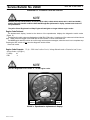
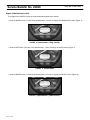
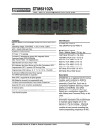
Figure 11. DPF, located underneath the roadside, rear service compartment.
Figure 12. DPF components
Item
Description
1
Diesel Particulate Filter
2
Pressure Sensor Line
3
Temperature Sensor Electrical Connector
4
Catalyst Module
5
Band Clamps
6
Outlet Module
7
Support Brace
Printed in Canada
20
Service Bulletin No. 2969C
DATE APR. 13, 2009 PAGE
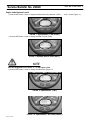
REGENERATION
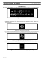
MCI coaches with an EPA 2007 engine are equipped with three specific tell-tales for the regeneration system:
Figure 13. LH tell-tale.
1. Regeneration Tell-tale Lamp ( DPF ). Tell-tale illuminates when a regeneration is required. Tell-tale is OFF
during regeneration.
Figure 14. Regeneration Tell-tale Lamp
2. High Exhaust Temperature Tell tale Lamp ( HET ). This tell-tale will illuminate when the coach is moving less
than 5 mph ( approximately ) and the exhaust outlet temperature exceeds the predetermined level.
Figure 15. High Exhaust Temperature Tell tale Lamp
3. Malfunction Indicator Tell tale Lamp ( MIL ) ( on DDC engines ONLY ). This tell-tale indicates a failure of a
emission system component on DDC equipped coaches only.
Figure 16. Malfunction Indicator Tell tale Lamp (MIL) (DDC ONLY)
Printed in Canada
21
Service Bulletin No. 2969C
DATE APR. 13, 2009 PAGE
On MCI coaches there are three regeneration modes:
1. Passive Regen --- Normal engine operation provides sufficient exhaust temperature for regen to occur with
no noticeable effects to the driver.
2. Active Regen --- Normal engine operation does not provide sufficient exhaust temperature for passive
regent to occur. Regeneration system raises the exhaust temp for regen to occur.
3. Stationary Regen --- Normal operation of the engine will not allow for passive or active regeneration to
occur. The operator must initiate a regen with the remote switch located in the curbside, rear side service
compartment.
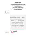
The regeneration toggle switch is located in the RH, rear service compartment ( Figure 17 ).
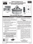
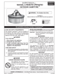
Figure 17. Regeneration switch, located in the curbside, rear service compartment
To avoid serious personal injury or property damage, ensure that no persons or objects are at, or within two
feet of the exhaust outlet at any time during a regeneration.
Ensure that exhaust and outlet are clear of any trash, grasses, or other vegetation or debris.
Use extreme caution during a stationary regeneration, as exhaust gas tail pipe outlet
temperatures can exceed 900 degrees F ( 482 degrees C ).
Stationary regererations are to be performed outdoors only.
DO NOT leave the coach unattended during a stationary regeneration.
DO NOT perform inside a garage or maintenance facility.
DO NOT attach an exhaust extraction hose to the exhaust outlet.
NOTE
If the coach will be idling for an expended period of time, or overnight, with the DPF tell tale lamp
illuminated, a stationary regen is required to avoid unnecessary engine derate or shutdown.
Printed in Canada
22
Service Bulletin No. 2969C
DATE APR. 13, 2009 PAGE
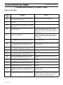
DPF and HET ( Regen ) Tell-tale Conditions
Regeneration Tell-tale
(DPF)
OFF
ON SOLID
High Exhaust Temp. Tell-tale Engine Response / Operator Action
(HET)
OFF
Engine responds normally.
No Driver action required
OFF
Engine responds normally.
Regeneration required.
Increase vehicle speed above 5 mph
for a minimum of twenty (20) minutes,
or,
perform a stationary regen within
two (2) hours.
OFF
ON SOLID /
Temperature Dependant
Engine responds normally.
Regeneration in process.
No driver action required.
Regen required.
FLASHING
OFF or ON SOLID /
Temperature Dependant
Perform a stationary regen within
one (1) hour.
Engine De---rated.
FLASHING w/CHECK ENG
Tell-tale
OFF or ON SOLID /
Temperature Dependant
Regen required.
Perform Stationary Regen within
thirty (30) minutes.
FLASHING w/CHECK ENG
Tell-tale and STOP ENG
Tell tale
OFF or ON SOLID /
Temperature Dependant
Engine de-rated or shutdown
engaged.
Regeneration locked out.
Flashing SEL tell-tale indicates thirty
(30) seconds to shutdown.
Once shutdown, coach may need to
be towed.
Service required.
Printed in Canada
23
Service Bulletin No. 2969C
DATE APR. 13, 2009 PAGE
24
The CHECK MESSAGE tell-tale illumination indicates that a message regarding additional tell-tale information is
displayed on the alphanumeric display of speedometer. Dependant of the message displayed, a buzzer may accompany
the message.
FIGURE 18 -- LH Tell-tale Cluster
Move the coach to a safe parking area to view the message displayed on the alphanumeric display of speedometer.
After the message has been recorded, the operator can press the SET button ( RH side of the speedometer ) to dismiss
the message. The CHECK MESSAGE tell-tale will remain illuminated, but the message will not appear until the system
re-broadcasts the signal.
SET
button
FIGURE 19. Speedometer alphanumeric display.
The tell-tale information displayed on the alphanumeric display of speedometer are Lavatory Emergency
( displayed as LAVTORY ) and Baggage Lights ( BAG LTS ).
Printed in Canada
Service Bulletin No. 2969C
DATE APR. 13, 2009 PAGE
25
ENGINE SPECIFIC REGENERATION STRATEGY / CUMMINS ( ISM )
Before a parked or stationary regen can occur, these required functions must occur:
The DPF tell-tale lamp illuminated ( solid or flashing ),
Locate the transmission push---button shift selector. While making a service brake application, cycle the push---button
shift selector by pressing NEUTRAL---DRIVE---NEUTRAL. NEUTRAL selected on the transmission push-button shift
selector,
Locate the park brake. While making a service brake application, cycle the Park Brake ON---OFF---ON. Park brake is
applied,
The HVAC system is OFF.
Vehicle speed is 0 MPH.,
Engine running at idle speed ( Not fast idle ),
Service brake released,
DOC inlet air temp >300 degrees F ( 149 degrees C ),
Hold up the regen switch to the ”Initiate position” for 5 seconds and release. Do not move the switch to the ”Regen
Inhibit” position.
Stationary Regen Operation
DPF lamp will illuminate for 1 sec and turn off for the duration of regen,
Engine RPM will rise to 1600 RPM,
HET lamp will illuminate after approx. 3 minutes indicating high exhaust temperature during the regen and remain on
until after the exhaust is below the predetermined temp,
Duration of the regen is 20---40 minutes depending on the level of soot in the DPF,
When the regen is completed, all telltales will be OFF, engine RPM will return to idle.
A Stationary Regen can be disabled by:
Disabling one or more of the Stationary Regen requirements, or,
Toggle the Regen switch to “Inhibit position” for 5 seconds, or
Turn OFF the ignition switch.
An Active Regen can be disabled by:
Reducing vehicle speed to below 5 mph.
Procedure complete.
Printed in Canada