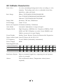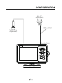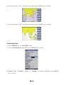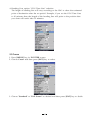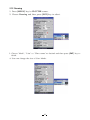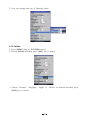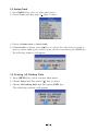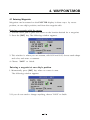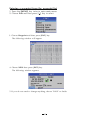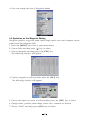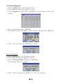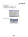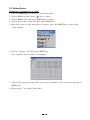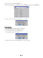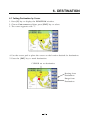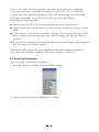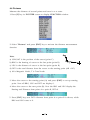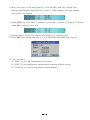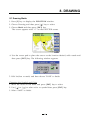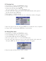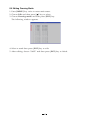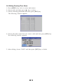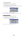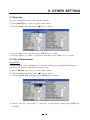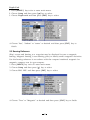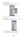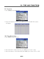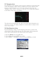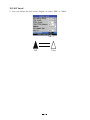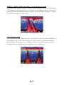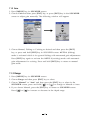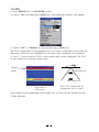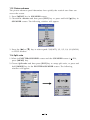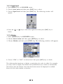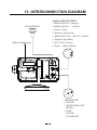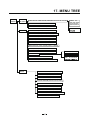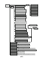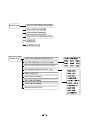
1
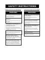
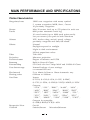
KCOMBO-7
OPERATOR'S MANUAL
GPS CHART PLOTTER WITH FISHFINDER
SAFETY INSTRUCTIONS
Safety Instructions for the Operator
Safety Instructions for the Installer
WARNING
WARNING
Do not open the equipment.
Only qualified personnel should work
inside the equipment.
Do not disassemble or modify the
equipment.
Fire,electrical shock or serious injury
can result.
Immediately turn off the power at
the switchboard if the equipment is
emitting smoke or fire.
Continued use of the equipment can
cause fire or electrical shock.Contact
a ONWA agent for service.
Use the proper fuse.
Use of a wrong fuse can damage the
equipment or cause fire.
Be sure the power supply is
compatible with the equipment.
Incorrect power supply may cause the
equipment to overheat.
The useable temperature range
-15ć to 55ć for the display unit.
Use of the equipment out of those
ranges may damage the equipment.
Do not open the cover unless totally
familiar with electrical circuits and
service manual.
Improper handling can result in
electrical shock.
Turn off the power at the switchboard
before beginning the installation.
Fire or electrical shock can result if the
power is left on.
Be sure that the power supply is
compatible with the voltage rating
of the equipment.
Connection of an incorrect power
supply can cause fire or equipment
damage.
Use the proper fuse.
Use of a wrong fuse can damage the
equipment or cause fire.
CONTENTS
FOREWORD Ă ĂĂ Ă Ă ĂĂ ĂĂ ĂĂ Ă Ă ĂĂ ĂĂ ĂĂĂ Ă Ă ĂĂ ĂĂ1
MAIN PERFORMANCE AND SPECIFICATIONSĂĂĂĂĂĂĂĂĂĂĂĂ2
CONFIGERATION ĂĂ ĂĂĂ ĂĂ Ă Ă ĂĂĂ ĂĂ ĂĂ ĂĂĂ ĂĂ ĂĂ6
1 OPERATION OVERVIEWĂĂ ĂĂ Ă Ă ĂĂ ĂĂ ĂĂĂ ĂĂ ĂĂ ĂĂ ĂĂ Ă Ă7
1.1 Keypad instructionĂĂĂĂĂĂĂĂĂĂĂĂĂĂĂĂĂĂĂĂĂĂĂĂ7
1.2 Turning ON and OFF PowerĂĂĂĂĂĂĂĂĂĂĂĂĂĂĂĂĂĂĂĂĂ8
1.3 Adjusting Brilliance and DIMĂĂĂĂĂĂĂĂĂĂĂĂĂĂĂĂĂĂĂĂ8
1.4 Display Modes ĂĂĂĂĂĂĂĂĂĂĂĂĂĂĂĂĂĂĂĂĂĂĂĂĂĂ9
2 PLOTTER DISPLAY OVERVIEWĂĂĂĂĂĂĂĂĂĂĂĂĂĂĂĂĂĂĂĂĂ10
2.1 Choosing the Display Range ĂĂĂĂĂĂĂĂĂĂĂĂĂĂĂĂĂĂĂĂ10
2.2 Moving the Cursor ĂĂĂĂĂĂĂĂĂĂĂĂĂĂĂĂĂĂĂĂĂĂĂĂ10
2.3 Panning the PLOTTER DisplayĂĂĂĂĂĂĂĂĂĂĂĂĂĂĂĂĂĂ11
2.4 Centering Own Ship's PositionĂĂĂĂĂĂĂĂĂĂĂĂĂĂĂĂĂĂĂ11
2.5 CoordinatesĂĂĂĂĂĂĂĂĂĂĂĂĂĂĂĂĂĂĂĂĂĂĂĂĂĂĂ11
2.6 MapĂĂĂĂĂĂĂĂĂĂĂĂĂĂĂĂĂĂĂĂĂĂĂĂĂĂĂĂĂĂĂ12
2.7 Perspective ViewĂĂĂĂĂĂĂĂĂĂĂĂĂĂĂĂĂĂĂĂĂĂĂĂĂĂ12
2.8 Heading LineĂĂĂĂĂĂĂĂĂĂĂĂĂĂĂĂĂĂĂĂĂĂĂĂĂĂĂĂ13
2.9 CursorĂĂĂĂĂĂĂĂĂĂĂĂĂĂĂĂĂĂĂĂĂĂĂĂĂĂĂĂĂĂĂ14
2.10 Ship shape/colorĂĂĂĂĂĂĂĂĂĂĂĂĂĂĂĂĂĂĂĂĂĂĂĂĂĂĂ15
2.11 Range CircleĂĂĂĂĂĂĂĂĂĂĂĂĂĂĂĂĂĂĂĂĂĂĂĂĂĂĂ15
2.12 DrawingĂĂĂĂĂĂĂĂĂĂĂĂĂĂĂĂĂĂĂĂĂĂĂĂĂĂĂĂĂ16
2.13 PaletteĂĂĂĂĂĂĂĂĂĂĂĂĂĂĂĂĂĂĂĂĂĂĂĂĂĂĂĂĂĂĂ17
2.14 Map DirectionĂĂĂĂĂĂĂĂĂĂĂĂĂĂĂĂĂĂĂĂĂĂĂĂĂĂĂ18
3 TRACKĂ Ă ĂĂ Ă ĂĂ Ă Ă ĂĂ Ă ĂĂ Ă Ă Ă Ă Ă ĂĂ Ă Ă Ă Ă Ă ĂĂ Ă Ă19
3.1 Changing Track Plotting Interval, Stopping Plotting ĂĂĂĂĂĂĂĂĂĂĂĂ19
3.2 Displaying the Track ĂĂĂĂĂĂĂĂĂĂĂĂĂĂĂĂĂĂĂĂĂĂĂĂĂ20
3.3 Creating Track DataĂĂĂĂĂĂĂĂĂĂĂĂĂĂĂĂĂĂĂĂĂĂĂĂĂĂ20
3.4 Erasing TrackĂĂĂĂĂĂĂĂĂĂĂĂĂĂĂĂĂĂĂĂĂĂĂĂĂĂĂĂ21
3.5 Erasing All Backup DataĂĂĂĂĂĂĂĂĂĂĂĂĂĂĂĂĂĂĂĂĂĂĂĂ21
4 WAYPOINT/MOBĂĂĂĂĂĂĂĂĂĂĂĂĂĂĂĂĂĂĂĂĂĂĂĂĂĂĂĂ22
4.1 Entering WaypointsĂĂĂĂĂĂĂĂĂĂĂĂĂĂĂĂĂĂĂĂĂĂĂĂĂĂ22
4.2 Entering the MOB MarkĂĂĂĂĂĂĂĂĂĂĂĂĂĂĂĂĂĂĂĂĂĂĂĂ24
4.3 Displaying Waypoint NameĂĂĂĂĂĂĂĂĂĂĂĂĂĂĂĂĂĂĂĂĂĂ24
4.4 Operation on the Waypoint EditingĂĂĂĂĂĂĂĂĂĂĂĂĂĂĂĂĂĂ25
4.5 Erasing WaypointsĂĂĂĂĂĂĂĂĂĂĂĂĂĂĂĂĂĂĂĂĂĂĂĂĂ26
5 ROUTESĂ ĂĂĂĂĂ ĂĂĂĂ ĂĂĂĂ ĂĂĂĂĂ ĂĂĂĂ ĂĂĂĂ Ă27
5.1 Creating RoutesĂĂĂĂĂĂĂĂĂĂĂĂĂĂĂĂĂĂĂĂĂĂĂĂĂĂĂ27
5.2 Editing RoutesĂĂĂĂĂĂĂĂĂĂĂĂĂĂĂĂĂĂĂĂĂĂĂĂĂĂĂ29
5.3 Erasing RoutesĂĂĂĂĂĂĂĂĂĂĂĂĂĂĂĂĂĂĂĂĂĂĂĂĂĂĂ30
6 DESTINATIONĂĂĂĂĂĂĂĂĂĂ ĂĂĂĂĂĂĂĂĂ ĂĂĂĂĂĂĂĂ32
6.1 Setting Destination by CursorĂĂĂĂĂĂĂĂĂĂĂĂĂĂĂĂĂĂĂĂ32
6.2 Setting Destination by Waypoint (WPT)ĂĂĂĂĂĂĂĂĂĂĂĂĂĂĂ33
6.3 Setting Route as DestinationĂĂĂĂĂĂĂĂĂĂĂĂĂĂĂĂĂĂĂĂĂ33
6.4 Setting Track Data as DestinationĂĂĂĂĂĂĂĂĂĂĂĂĂĂĂĂĂĂĂ35
6.5 Canceling DestinationĂĂĂĂĂĂĂĂĂĂĂĂĂĂĂĂĂĂĂĂĂĂĂĂ36
6.6 DistanceĂĂĂĂĂĂĂĂĂĂĂĂĂĂĂĂĂĂĂĂĂĂĂĂĂĂĂĂĂ37
7 ALARMĂ Ă Ă ĂĂ Ă ĂĂ Ă ĂĂ Ă Ă ĂĂ Ă ĂĂ Ă ĂĂ Ă Ă Ă Ă ĂĂ Ă Ă Ă39
7.1 Anchor Drag AlarmĂĂĂĂĂĂĂĂĂĂĂĂĂĂĂĂĂĂĂĂĂĂĂĂĂ39
7.2 Arrival AlarmĂĂĂĂĂĂĂĂĂĂĂĂĂĂĂĂĂĂĂĂĂĂĂĂĂĂĂ40
7.3 XTE (Cross-Track Error) Alarm ĂĂĂĂĂĂĂĂĂĂĂĂĂĂĂĂĂĂĂĂ41
7.4 Speed AlarmĂĂĂĂĂĂĂĂĂĂĂĂĂĂĂĂĂĂĂĂĂĂĂĂĂĂĂĂ41
7.5 Voltage AlarmĂĂĂĂĂĂĂĂĂĂĂĂĂĂĂĂĂĂĂĂĂĂĂĂĂĂĂ42
7.6 Time AlarmĂĂĂĂĂĂĂĂĂĂĂĂĂĂĂĂĂĂĂĂĂĂĂĂĂĂĂĂ42
7.7 Buzzer Type SelectionĂĂĂĂĂĂĂĂĂĂĂĂĂĂĂĂĂĂĂĂĂĂĂĂ43
8 DRAWINGĂĂĂĂĂ ĂĂĂ ĂĂ ĂĂĂ ĂĂĂ ĂĂĂĂĂ ĂĂĂ ĂĂĂ ĂĂ 44
8.1 Drawing MarksĂĂĂĂĂĂĂĂĂĂĂĂĂĂĂĂĂĂĂĂĂĂĂĂĂĂĂ44
8.2 Drawing LinesĂĂĂĂĂĂĂĂĂĂĂĂĂĂĂĂĂĂĂĂĂĂĂĂĂĂĂ45
8.3 Drawing Place nameĂĂĂĂĂĂĂĂĂĂĂĂĂĂĂĂĂĂĂĂĂĂĂĂ 45
8.4 Editing Drawing MarksĂĂĂĂĂĂĂĂĂĂĂĂĂĂĂĂĂĂĂĂĂĂĂ46
8.5 Editing Drawing LinesĂĂĂĂĂĂĂĂĂĂĂĂĂĂĂĂĂĂĂĂĂĂĂ47
8.6 Editing Drawing Place NameĂĂĂĂĂĂĂĂĂĂĂĂĂĂĂĂĂĂĂĂ48
8.7 Erasing Drawing MarksĂĂĂĂĂĂĂĂĂĂĂĂĂĂĂĂĂĂĂĂĂĂĂ49
8.8 Erasing Drawing LinesĂĂĂĂĂĂĂĂĂĂĂĂĂĂĂĂĂĂĂĂĂĂĂ50
8.9 Erasing Drawing Place NameĂĂĂĂĂĂĂĂĂĂĂĂĂĂĂĂĂĂĂĂĂ51
9 OTHER SETTINGĂĂĂĂĂĂĂĂĂĂĂĂĂĂĂĂĂĂĂĂĂĂĂĂĂ52
9.1 Map Scale ĂĂĂĂĂĂĂĂĂĂĂĂĂĂĂĂĂĂĂĂĂĂĂĂĂĂĂĂĂĂ52
9.2 Unit of MeasurementĂĂĂĂĂĂĂĂĂĂĂĂĂĂĂĂĂĂĂĂĂĂĂĂĂ Ă52
9.3 Bearing ReferenceĂĂĂĂĂĂĂĂĂĂĂĂĂĂĂĂĂĂĂĂĂĂĂĂĂĂ Ă53
9.4 Magnetic VariationĂĂĂĂĂĂĂĂĂĂĂĂĂĂĂĂĂĂĂĂĂĂĂĂĂĂ Ă54
9.5 DeviationĂĂĂĂĂĂĂĂĂĂĂĂĂĂĂĂĂĂĂĂĂĂĂĂĂĂĂĂĂ ĂĂ55
9.6 TimeĂĂĂĂĂĂĂĂĂĂĂĂĂĂĂĂĂĂĂĂĂĂĂĂĂĂĂĂĂĂ ĂĂ55
9.7 TTG/ETA speedĂĂĂĂĂĂĂĂĂĂĂĂĂĂĂĂĂĂĂĂĂĂĂĂĂ Ă56
9.8 Key beep ĂĂĂĂĂĂĂĂĂĂĂĂĂĂĂĂĂĂĂĂĂĂĂĂĂĂĂ Ă56
9.9 Wind screenĂĂĂĂĂĂĂĂĂĂĂĂĂĂĂĂĂĂĂĂĂĂĂĂĂĂ Ă56
9.10 GPS setting ĂĂĂĂĂĂĂĂĂĂĂĂĂĂĂĂĂĂĂĂĂĂĂĂĂĂ Ă57
9.11 NMEA data display ĂĂĂĂĂĂĂĂĂĂĂĂĂĂĂĂĂĂĂĂĂĂĂ59
10 THE AIS FUNTIONĂĂĂĂĂĂĂĂĂĂĂĂĂĂĂĂĂĂĂĂĂĂĂĂĂĂĂ60
10.1 Vessels listĂĂĂĂĂĂĂĂĂĂĂĂĂĂĂĂĂĂĂĂĂĂĂĂĂĂĂĂĂĂ60
10.2 The collision alarmĂĂĂĂĂĂĂĂĂĂĂĂĂĂĂĂĂĂĂĂĂĂĂĂĂĂ 60
10.3 Own ship's informationĂĂĂĂĂĂĂĂĂĂĂĂĂĂĂĂĂĂĂĂĂĂĂĂ61
10.4 Chart ScreenĂĂĂĂĂĂĂĂĂĂĂĂĂĂĂĂĂĂĂĂĂĂĂĂĂĂĂĂĂ61
10.5 View AIS vessels' information on chart screenĂĂĂĂĂĂĂĂĂĂ62
10.6 Check all AIS ships within the scope of Radar (AIS screen)ĂĂĂĂĂ62
10.7 Emergency alarmĂĂĂĂĂĂĂĂĂĂĂĂĂĂĂĂĂĂĂĂĂĂĂĂĂ63
10.8 Entry/Departure settingĂĂĂĂĂĂĂĂĂĂĂĂĂĂĂĂĂĂĂĂĂĂĂĂ63
10.9 AIS VesselĂĂĂĂĂĂĂĂĂĂĂĂĂĂĂĂĂĂĂĂĂĂĂĂĂĂĂĂĂĂ64
11 ECHO SOUNDER OVERVIEWĂĂĂĂĂĂĂĂĂĂĂĂĂĂĂĂĂĂĂĂ65
11.1 Sonar mode ĂĂĂĂĂĂĂĂĂĂĂĂĂĂĂĂĂĂĂĂĂĂĂĂĂĂĂĂĂĂ65
11.2 GainĂĂĂĂĂĂĂĂĂĂĂĂĂĂĂĂĂĂĂĂĂĂĂĂĂĂĂĂĂĂĂĂĂĂ67
11.3 RangeĂĂĂĂĂĂĂĂĂĂĂĂĂĂĂĂĂĂĂĂĂĂĂĂĂĂĂĂĂĂ ĂĂĂ67
11.4 TVGĂĂĂĂĂĂĂĂĂĂĂĂĂĂĂĂĂĂĂĂĂĂĂĂĂĂĂĂĂĂĂ ĂĂĂ68
11.5 Pic. AdvanceĂĂĂĂĂĂĂĂĂĂĂĂĂĂĂĂĂĂĂĂĂĂĂĂĂĂĂĂĂ69
11.6 Split ratio ĂĂĂĂĂĂĂĂĂĂĂĂĂĂĂĂĂĂĂĂĂĂĂĂĂĂĂĂĂĂ69
11.7 Sonar MenuĂĂĂĂĂĂĂĂĂĂĂĂĂĂĂĂĂĂĂĂĂĂĂĂĂĂĂĂ70
11.8 AlarmĂĂĂĂĂĂĂĂĂĂĂĂĂĂĂĂĂĂĂĂĂĂĂĂĂĂĂĂĂ ĂĂĂ75
11.9 System MenuĂĂĂĂĂĂĂĂĂĂĂĂĂĂĂĂĂĂĂĂĂĂĂĂĂ ĂĂ76
11.10 Data FieldĂĂĂĂĂĂĂĂĂĂĂĂĂĂĂĂĂĂĂĂĂĂĂĂĂĂĂĂĂ77
12 INSTALLATIONĂĂ ĂĂ ĂĂĂ ĂĂ ĂĂĂ ĂĂĂ ĂĂ ĂĂĂ ĂĂ Ă ĂĂ78
13 INTERCONNECTION DIAGRAWĂĂĂĂĂĂĂĂĂĂĂĂĂĂĂĂĂĂĂĂ79
14 DISPLAY SIZEĂĂĂĂĂĂĂĂĂĂĂĂĂĂĂĂĂĂĂĂĂĂĂĂĂĂĂ80
15 SHORTCUTSĂĂĂĂĂĂĂĂĂĂĂĂĂĂĂĂĂĂĂĂĂĂĂĂĂĂĂ81
16 DATA IN/OUT DESCRIPTIONĂĂĂĂĂĂĂĂĂĂĂĂĂĂĂĂĂĂĂĂĂĂ82
17 MENU TREEĂĂĂĂĂĂĂĂĂĂĂĂĂĂĂĂĂĂĂĂĂĂĂĂĂĂĂĂĂ83
18 ABBREVIATIONSĂĂĂĂĂĂĂĂĂĂĂĂĂĂĂĂĂĂĂĂĂĂĂĂĂĂĂ89
19 GLOSSARYĂĂĂĂĂĂĂĂĂĂĂĂĂĂĂĂĂĂĂĂĂĂĂĂĂĂĂĂĂ90
FOREWORD
The KCOMBO ONWA GPS PLOTTER aid are specially designed for the vessel
traffic management, ONWA is a professional brand of the domestic and foreign
navigation products.
The products are designed to be all-sealed and waterproof, can be rapid
position-fixing and resistant to poor environment. The software is powerful by
using the advanced ARM9 processorsˈcan be capable to display faster, and the
design for operation is professional and reasonable, can be easy to use. The
built-in Large-capacity map storage space provides intuitive and accurate
indication to navigation. It's applicable to the navigation and position-fixing of
various vessels at sea and rivers, as well as the hydrographic information
collection, river management, etc. For the application for different types of the
products please refer to the following˖
g g g g g g
FEATURES
Easy to operate
Ultra high brightness LCD, viewable under strong sunlight
Compatiable with dual mapping system,C-MAP NT MAX and ONWA K-Chart
Built-in GPS antenna, external antenna can be used as an option
Digital HD fishfinder technology
Built-in commercial fishfinder module which is widely using in worldwide
g
commercial fishing bost
IPX7 waterproof panel
1
MAIN PERFORMANCE AND SPECIFICATIONS
Plotter Characteristics
Waypoints/icons
12000 user waypoints with name, symbol.
3 system waypoints: MOB, Start , Cursor
10 proximity waypoints
Routes
Tracks
Max 30 routes. And up to 170 points for each one
8000 points automatic track log;
10 saved tracks (up to 8000 track points each).
Let you retrace your path in both directions
Alarms
XTE, Anchor drag, arrival, speed, voltage,
proximity waypoint and time,AIS alarm.
Palette
Normal
Daylight exposed to sunlight
Night in dark environment
Tides
Projection
Position format
Basemap
External Map
NOAA paperchart colors
Tide data
Mercator projection
Degree of minutes and UTM
Built-in Onwa K-Chart
User data storage
SD Cards slot for C-Map MAX and ONWA K-Chart
Internal backup of user settings,
Plot Interval
or external SD-card
5s to 60min 0.01nm to 10nm Automatic way
Plotting scales
Nav Data
0.001nm to 1000nm
Inputs:
$--GGA, $--GLL,$--GSA, $--GSV, $--RMC,
$--VTG, $--ZDA, $--VWR,$--VWT,$--MWD, $--VPW
Outputs:
ĀGGAā,Ā GLLā,ĀRMCā,ĀAAMā, ĀAPAā,
ĀAPB ā, ĀBODā , ĀBWCā , ĀBWR ā,ĀDBTā
ĀDPT ā, āHDTā, Ā MTWā, ĀRMB ā, ĀTLLā ,
ĀVTGā, ĀWPL ā, ĀXTEā , ĀZDAā , ĀZTGā ,
ĀZDL ā, ĀMWDā, ĀVPWā,ĀVWRā, ĀVWTā,
Outputs for autopilot:
$--APB,$--BOD,$--XTE,$--APA
Perspective View
Celestial
On/off
Sunrise/Sunset
2
Moonrise/Moonset
Power Supply
10.5 to 35VDC, current drain<1.0A at 12V
Physical
Size:
243mm(H)X155mm(W)X82mm(D)
Weight:
0.6kg
Display:
7-inches ColorTFT day-view LCD 800h 600 pixels
Input & Output Port: one opto-isolated input Port
one RS232 Output Port
Waterproofing:
Display unit: IPX5
Temperature range: Display unit: -15ć to +55ć
Antenna unit: -25ć to +70
ć
GPS Receiver Characteristics
Receiver:
50 parallel channel GPS receiver continuously tracks and
uses up to 50 satellites to compute and update your position
Acquisition time:
Cold start: 60 seconds average
Hot start: 45 second average
Update rate:
1/second,continuous
Position: 2.5 meters(95%) without S/A
Velocity: 0.1 meter/sec without S/A
Time: 100ns synchronized to GPS time
Dynamics:
Altitude: 50,000m Max
Velocity: 500 m/s
Acceleration: 4g Max
Datum:
WGS 84 and user define
3
Equipment List
Standard
1. Display unit
2. Operator manual
3. Installation materials and standard spare parts
AIS interface
Data input:
NMEA 0183, RS232
Baud rate:
38,400
Option Accessories
1) GPS antenna KA-07
2) Transducers
Dual Frequency Thru-Hull Transducer
- 600W Bronze NMM40-50/200
- 600W Plastic NBM40-50/200
- 600W Airmar Bronze Transducer w/Temp seosor B45
Dual Frequency Transom Mount Transducer
- 600W Onwa Transducer w/Temp seosor KTD-520_TM
- 600W Airmar transducer w/Temp seosor P58
3) Temperature seosor
Onwa Thru-Hull temperature seosor KTS-10K_TH
Onwa Transom Mount Temperature seosor KTS-10K_TM
4
HD Fishfinder Characteristics
Echo Color
16 colors (including background color) according to echo
intensity. The background color is selectable from blue,
light blue, white and black.
Basic Range
Meters 5/10/20/40/80/150/200/300/600/1000
Feet 15/30/60/120/200/400/600/1000/2000/3000
Fathoms 3/5/10/20/40/80/100/150/300/600
Range Shift
80 meters, 200 feet, 100fathoms
Zoom Range
Times 2,3,4,6
Bottom Lock Expansion 5/10meters,10/20feet, 2/5fathoms
Auto Mode
Automatic adjustment of range and gain
Display Mode
High Frequency (200KHz),Low Frequency (50KHz), Dual
(200K and 50K 1/2display on each), Zoom (200KHz and
50KHz zoom) and A-scope Display
Zoom Display
Marker Zoom, Bottom Zoom and Bottom-lock Expansion
Display Advance Speed Lines/TX:Freeze,1/8,1/4,1/2,1/1,2/1
TX Frequency
50 and 200kHz (alternately transmitted)
Power Output
600W
Pulse-length/TX rate
Display End Depth (m)
5
10
20
40
80
150
200
300
600
1000
Pulse-Length (ms) 200K
0.12
0.22
0.32
0.52
0.92
1.02
1.02
1.02
1.02
1.02
Pulse-Length (ms) 50K
0.17
0.27
0.37
0.57
0.97
1.07
1.07
1.07
1.07
1.07
TX Rate (Pulse/min)
2400
1500
857
444
231
125
95
63
38
30
Interference Rejecter
Rejects unwanted signals by comparing last and present
echoes in strength.
Alarm
Fish and Bottom alarms, Temperature alarm (sensor
required)
5
CONFIGERATION
KA-07
(Optional)
10M or 15M
Transducer
(Optional)
Display Unit
6
1. OPERATION OVERVIEW
1.1 Keypad instruction
Plotter function: Moving the cursor upward or to change the setting.
Sounder function: Moving the VRM upward.
Plotter function: Moving the cursor to the right.
Sounder function:
Long Press - Activates feeding rate selection for picture advancement
Short Press - Setting the depth range (setting upper range limit).
MENU
Pressing it once displays the menu of the current page, pressing
it twice enters the main menu.
Plotter + Sounder Function:
Long press - Activates split ratio selection.
Short Press - Displays the menu of the screen that has
MODE
>50% screen coverage.
Display the seven main screens circularly, turn over the
listed interfaces.
Plotter Function: Press and hold to change track color.
Sounder Function: Press and hold to activate sonar mode selection.
ESC
Withdraw from an optional operation, or display the previous
page in reverse-cycle order.
Plotter function: Press and hold to switch track ON/OFF.
ENT
Confirms the input or data.
Plotter function: Long Press - Activates Drawing Mark option.
Short Press - Activates waypoint attribute edit
window.
Sounder function: Long Press - To switch from manual gain to
automatic gain and vice versa.
Short Press - To adjust gain level.
Plotter and AIS Function: Enlarges the scale of the maps and charts.
Sounder Function: Decreases the depth range for shallow waters.
Plotter and AIS Function: Reduces the scale of the maps and charts.
Sounder Function: Increases the depth range for deeper water.
F
Plotter function: Display other function (GOTO, tide table, search, etc.) menu.
Sounder function: Provides signal level selection. Eliminates low
intensity echoes (up to light-blue echoes) each level.
MOB
The MOB mark denotes man overboard position.
Long Press - Turn the power ON/OFF.
Short Press - Adjust the screen brightness and control panel dim. .
7
1.2 Turning ON and OFF Power
Turning on the power
Press the [
] key. The unit beeps and displays the "ONWA" logo. After a few
seconds, it starts up with the last used display mode.
Turning off the power
Press and hold down the [
] key until the screen goes blank
(about four seconds).
1.3 Adjusting Brilliance and DIM
You can adjust display brilliance as shown below.
1. Press the [
] key. The adjusting window appears.
BRILL
(1~8)
DIM
(1~8)
EXIT [ENT]
2. Press [
] or [ ]
to
adjust
LCD
3. Press [ ] or [ ] to adjust keypad backlight .
4. Press the [ESC] key to confirm and exit.
8
display brightness.
1.4 Display Modes
Your unit has eleven display modes: PLOTTER SCREEN, NAVIGATOR SCREEN,
WIND SCREEN, POSITION SCREEN, SATELLITE SCREEN , HIGHWAY SCREEN,
AIS SCREEN , SOUNDER SCREEN and PLOTTER + SOUNDER SCREEN.
Press the [MODE] key to choose a display mode. Each time the key is pressed, the
display mode changes in the sequence shown below.
PLOTTER
NAVIGATOR
PLOTTER + SOUNDER
POSITION
SOUNDER
WIND
AIS
SATELLITE
HIGHWAY
9
2. PLOTTER DISPLAY OVERVIEW
2.1 Choosing the Zoom Display Range
You may press
to Zoom In and
to Zoom Out as desired on the PLOTTER
display.
2.2 Moving the Cursor
Press the cursor pad to move the cursor. The cursor moves in the direction of the
pressed arrow. Whether up [
], down [
] , left [
], right [
] or diagonal [
].
Cursor Position Turned On
Cursor position is displayed in latitude and longitude at the top left corner of
the PLOTTER display when the cursor is on. The range and bearing from own
ship to the cursor appears at the top left corner of the display too.
Cursor position
Range and Bearing
from vessel to cursor
Data Field
Cursor Position Turned Off
Press the [ESC] key to clear the cursor. Cursor position data will disappear when
the cursor is off.
10
2.3 Panning the PLOTTER Display
Using the cursor, pan left, right, up or down on your desired area. Place the cursor
at the edge of the screen to start panning. The display shifts in the direction
opposite to cursor pad operation.
2.4 Centering Own Ship's Position
Press the [ESC] key for centering own ship's position.
2.5 Coordinates
Coordinate Systems are ways of splitting up the world in order to form transferable
units (numbers) that relate to points on a map.
1. Press [MENU] key in PLOTTER screen.
2. Choose Coordinates and then press [ENT] key to select.
3. Choose "N/E" or "UTM " as desired then press [ENT] key to finish.
11
2.6 Map
1. Press [MENU] key in PLOTTER screen.
2. Choose Map and then press [ ] key to select.
3. Choose the layer "ON" or "OFF " as desired and then press [ ENT] key to finish.
(K-Chart)
(C-MAP)
2.7 Perspective View
1. Press [MENU] key in PLOTTER screen.
2. Choose Perspective and then press [ENT] key to select.
3. Choose "ON " or "OFF" as desired and then press [ENT] key to finish.
12
4. Choose the layer "ON" as desired and then press [ ENT] key to finish.
5. Choose the layer "OFF" as desired and then press [ ENT] key to finish.
2.8 Heading Line
1. Press [MENU] key in PLOTTER screen.
2. Choose Heading Line and then press [ENT] key to select.
3. Choose "Off", "Variable", "Max" or "Timeline" as desired and then press [ENT]
key to finish.
13
4. Heading Line option: "COG Time Line" selection
The length of heading line will vary according to the SOG to show the estimated
point of destination after the set period. Example, if you set the COG Time Line
to 10 minutes then the length of the heading line will point to the position that
your boat will reach after 10 minutes.
2.9 Cursor
1. Press [MENU] key in PLOTTER screen.
2. Choose Cursor and then press [ENT] key to select.
3. Choose "Standard" or "Full Screen" as desired and then press [ENT] key to finish.
14
2.10 Ship shape/color
1. Press [MENU] key in PLOTTER screen.
2. Choose Ship shape/color and then press [ENT] key to select.
Press [
] key
and then press
[ENT] key .
2.11 Range Circle
1. Press [MENU] key in PLOTTER screen.
2. Choose Range Circle and then press [ENT] key to select.
3. Choose " ON " (if you choose " ON ", you need to input the radius of the
circle manually), or " OFF " as desired and then press [ ENT ] key to finish.
15
2.12 Drawing
1. Press [MENU] key in PLOTTER screen.
2. Choose Drawing and then press [ENT] key to select.
3. Choose "Mark", "Line" or "Place name" as desired and then press [ENT] key to
finish.
4. User can change the size of User Marks.
16
5. User can change the size of Drawing Lines.
2.13 Palette
1. Press [MENU] key in PLOTTER screen.
2. Choose Palette and then press [ ENT] key to select.
3. Choose "Normal ", "Daylight", "Night" or "NOAA" as desired and then press
[ENT] key to finish.
17
2.14 Map Direction
1. Press [MENU] key in PLOTTER screen.
2. Choose Map Direction and then press [ENT] key to select.
3. Choose "Normal", "North Up", "WPT Up" or "COURSE Up" as desired and then
press [ENT] key to finish.
18
3. TRACK
3.1 Changing Track Plotting Interval, Stop Plotting
When the track memory becomes full, the oldest track is erased to make room for the
latest.
1. Press the [MENU] key twice to enter main menu.
2. Choose Track record and then press [
] key to select.
3. Choose Track record mode and then press [ ] key select.
4. Choose "Time", "Distance", "Auto " or "Off ".
Time: Track is recorded and plotted at the time interval set.
Distance: Track is recorded and plotted at the distance interval set.
Auto: Plotting and recording interval changes with display range selected.
Off: Track is neither recorded nor plotted.
5. For Time and Distance, enter the recording interval as follows:
a) Press the [
] key to choose "5s ", "10s ", "30s ", "1min ", "5min ", "10min ",
"30min" or " 60min".
b) Use [
] or [
] to select value.
6. Press [ENT ] key to finish.
19
3.2 Displaying the Track
1. Press [MENU] key in PLOTTER screen.
2. Choose Track and then press [
] key to select.
3. Choose the color and if you want to turn it " ON " or " OFF " .
4. Press [ MENU ] key to finish.
3.3 Creating Track Data
1. Press the [MENU] key twice to enter main menu.
2. Choose Track Record and then press [
] key to select.
3. Choose Save Current Track and then press [ ENT] key.
The following window will appear.
Track Data can be used for navigation.
20
3.4 Erasing Track
1. Press [MENU] key twice to enter main menu.
2. Choose Erase and then press [
] key to select.
3. Choose Current track or Saved track.
4. If Saved track is chosen, press [
] key to choose the color that you want to
erase or choose ALL if you want to erase all tracks and then press [ENT] key.
The following window will appear:
3.5 Erasing All Backup Data
1. Press [MENU] key twice to enter main menu.
2. Choose Erase and then press [
] key to select.
3. Choose All backup data and then press [ENT] key.
The following window will appear.
21
4. WAYPOINT/MOB
4.1 Entering Waypoints
Waypoints can be entered on the PLOTTER display in three ways: by cursor
position, at own ship's position, and from the waypoint edit.
Entering a waypoint with the cursor
1. Use the cursor pad to place the cursor on the location desired for a waypoint.
2. Press the [ENT] key. The following window appears.
3. This window is where you can rename, edit LON and LAT, choose mark shape
and color, and enter a comment.
4. Choose "SAVE" to finish.
Entering a waypoint at own ship's position
1. Momentarily press [ENT] key when no cursor is seen.
The following window appears.
2. If you do not need to change anything, choose "SAVE " to finish.
22
Entering a waypoint from the waypoint list
1. Press the [MENU] key twice to enter main menu.
2. Choose Edit and then press [
] key to select.
3. Choose Waypoint and then press [ENT] key.
The following window will appear
4. Choose NEW then press [ENT] key.
The following window appears.
5. If you do not need to change anything, choose "SAVE " to finish.
23
4.2 Entering the MOB Mark
Only one MOB mark may be entered.
Each time the MOB mark is entered, the previous MOB mark and its position data
are over-written.
1. Long press the [MOB] key on any display mode.
The following display appears.
2. To set MOB position as destination, press [
] to choose "YES " and then press
[ENT] key. Choosing "NO" saves the position as a waypoint called "MOB ".
4.3 Displaying Waypoint Name
You may display waypoint name as follows:
1. Press the [MENU] key on the PLOTTER screen.
2. Choose Waypoint and then press the [ENT] key. The following window will
appear.
3. Choose "All", "Goto", "Route ", "Icon" or " OFF" as desired and then press the [ENT] key.
All: Displays all waypoint names.
Goto: Displays only the GOTO waypoint name.
Route: Displays all waypoint names when a route is set as destination.
OFF: Do not display any waypoint name.
24
4. User can change the size of Waypoint Marks
4.4 Operation on the Waypoint Editing
Waypoint position, waypoint name, mark shape, mark color and comment can be
edited from the Waypoint Edit.
1. Press the [ MENU] key twice to enter main menu.
2. Choose Edit and then press [ ] key to select.
3. Choose Waypoint and then press the [ ENT ] key.
The following window will appear.
4. Choose waypoint to edit and then press the [ ENT] key.
The following window will appear.
5. Choose the object you want to edit and then press the [ ENT] key to select.
6. Change name, position, mark shape, mark color, comment as desired.
7. Choose "SAVE" and then press [ ENT] key to finish.
25
4.5 Erasing Waypoints
1. Press the [MENU] key twice to main menu.
2. Choose Edit and then press [
] key to select.
3. Choose Waypoint and then press the [ENT] key. The following window will
appear.
4. Select a waypoint and press [ENT] key.
5. The confirm window will appear. Choose "ERASE" and then press [ ENT] key.
6. Choose "YES" and then press [ENT] key to finish.
01
Erase All Waypoints
1. Press the [MENU] key twice to enter main menu.
2. Choose Erase and then press [
] key to select.
3. Choose All waypoint/MOB and then press [ENT] key.
The confirming window will appear.
4. Choose "YES" and then press [ENT] key to erase all waypoints.
26
5. ROUTES
5.1 Creating Routes
1. Press [MENU] key twice to enter main menu.
2. Choose Edit and then press [
] key to select.
3. Choose Route and then press [ENT] key.
The following window will appear.
4. Choose " NEW" and then press [ENT] key.
The following window will appear.
27
5. Use [ ] or [ ] to enter the route name and then press [ ENT] key to finish.
The following will appear.
6. Choose the location (e.g. 01) and then press [ ENT] key.
A new window will open which will let you choose a waypoint.
7. Choose the waypoint name that you want to include in the route and then press
[ENT] key (e.g., 001). You can also create a new waypoint if needed.
8. Repeat step 6 and 7 until the route is complete.
28
5.2 Editing Routes
Replacing waypoints in a route
1. Press the [MENU] key twice to enter main menu.
2. Choose Edit and then press [
] key to select.
3. Choose Route and then press [ENT] key to select.
4. Choose the route to edit and then press [ENT] key.
5. Place the cursor on the waypoint to replace, press the [ENT] key to show the
route options.
6. Choose "Change" and then press [ ENT] key.
The waypoint select window will appear.
7. Choose the waypoint name that you want to include in the route and then press
[ENT] key.
8. Repeat step 5 to 8 until finish edit.
29
Permanently deleting a waypoint from a route
1. Press the [MENU] key twice to enter main menu.
2. Choose Edit and then press the [
] key to select.
3. Choose Route and then press [ENT] key to select.
4. Choose the route desired and then press [ENT] key to select.
5. Choose the waypoint you want to delete and then press [ENT] key to show the
route edit options.
6. Choose "Remove " and then press [ENT] key to finish.
5.3 Erasing Routes
1. Press the [MENU] key twice to enter main menu.
2. Choose Edit and then press [
] key to select.
3. Choose Route and then press the [ENT] key. The following window will appear.
30
4. Select a route then press [ENT] key.
5. The confirm window will appear. Choose "ERASE" and then press [ENT] key.
6. Choose "YES" and then press [ENT] key to finish.
01
Erase All Routes
1. Press the [MENU] key twice to enter main menu.
2. Choose Erase and then press [
] key to select.
3. Choose All routes and then press [ENT] key.
The confirming window will appear.
4. Choose "YES" and then press [ENT] key to erase all routes.
31
6. DESTINATION
6.1 Setting Destination by Cursor
1. Press [F] key to display the FUNCTION window.
2. Choose Goto cursor and then press [ENT] key to select.
3. The cursor appears with "?".
?
4. Use the cursor pad to place the cursor on the location desired for destination.
5. Press the [ ENT] key to mark destination.
CURSOR set as destination
Bearing from
Destination
Cursor
Start
Range from
Destination
32
6.2 Setting Destination by Waypoint (WPT)
1. Press the [F] key to display the FUNCTION window.
2. Choose Goto WPT and then press [ ENT] key to select.
3. The WAYPOINT list appears.
4. Choose a waypoint and then press [ENT] key to finish.
6.3 Setting Route as Destination
1. Press the [ F] key to display the FUNCTION window.
2. Select Goto route and then press [ENT] key to select.
33
3. The ROUTE list appears.
4. Choose a route and then press [ENT] key. The following window appears.
5. Choose "Forward " or "Reverse" in order to traverse the waypoints in the route, and
then press [ENT] key to finish.
[ROUTE 01]
Intermediate Point 2
(WPT B)
Intermediate Point 1
(WPT A)
FORWARD
(WPT SW)
(Arrival point)
REVERSE
(WPT 001)
(Starting point)
Intermediate point 1
(WPT C)
Meaning of forward and reverse
34
6.4 Setting Track Data as Destination
Track Data can be used for navigation.
1. Press the [F] key to display the FUNCTION window.
2. Choose Goto track and then press the [ENT] key to select.
3. The SAVED TRACK window will appear.
4. Choose the track that you want to set as destination, and then press [ENT] key .
5. Choose Forward or Reverese to start Goto track navigation.
35
Once a Goto track has been activated, the track will divide it into segments.
Up to 200 temporary waypoints are created (named T1,T2, T3, etc. and END)
to mark the most significant features of the track, duplicating your exact path
as closely as possible. To get the most out of the Goto track feature,
remember the following tips:
ƽ
ƽ
Always clear the track log at the point that you want to go back to.
There must be at least two track log points stored in memory to create a track
route.
ƽ
If the receiver is turned off or satellite coverage is lost during your trip, it will
draw a straight line between any point where coverage was lost and where it
resumed.
ƽ
If your track's changes in distance and direction are too complex, 200 waypoints
may not mark your path accurately.
The receiver then assigns the 200 waypoints to the most significant points of
your track, and simplifies segments with fewer changes in direction.
6.5 Canceling Destination
You can cancel a destination as follows.
1. Press the [ F] key to display the FUNCTION window.
2. Choose Stop goto and press [ENT] key to finish.
36
6.6 Distance
Measure the distance of several points and save it as a route.
1. Press [F] key in PLOTTER screen to display FUNCTION window.
2. Select "Distance" and press [ENT] key to activate the distance measurement
function.
A
Note:
a) LON/LAT is the position of the cursor (point C)
b) BRG is the bearing of cursor to the last point (point B)
B
Fig.3
c) LEG is the distance of cursor to the last point (point B)
d) DST is the total distance from the cursor to the starting point (AB + BC)
e) M is Magnetic North, T is True North
3. Move the cursor to the starting point (A) and press [ENT] to set up starting
point. Now all BRG, LEG and DST are display 0.
4. Move the cursor to the next point (B). Now the BRG and LEG display the
Bearing and Distance from point A to point B, DST=0.
5. Press [ENT] key, now DST= distance from point A to point B is shown, while
BRG and LEG turns to 0.
37
6. Move the cursor to the next point (C). Now the BRG and LEG displays the
Bearing and Distance from point B to point C. DIST displays the total distance
from point A to point B.
7. Press [ENT] key, now DIST = distance of point AB + distance of point BC is shown,
while BRG and LEG turns to 0.
8. Repeat steps 3, 4 and 5 to measure the distance of several points.
9. Press [ESC] key during the step 3, 4 or 5, the following menu will pop out.
10. You can select :
A) "SAVE " to save the measurement as a route.
B) "QUIT" to quit the distance measurement function without saving.
C) "CANCEL" to continue the distance measurement.
38
7. ALARM
There are six alarm conditions which generates both audio and visual alarms:
Arrival alarm, Anchor drag alarm, XTE (Cross-Track Error) alarm, Speed alarm ,
Voltage alarm and Timer alarm .
When the alarm setting is violated, the buzzer sounds and the name of the
offending alarm and the alarm icon appears on the display.
You can silence the buzzer and remove the alarm name indication by pressing any
key. The alarm icon remains on the screen until the reason for the alarm is cleared.
Alarm message
!
GPS NO FIX !
Alarm icon
Start
0 01
7.1 Anchor Drag Alarm
Anchor Drag Alarm informs you that own ship is moving when it should be at
rest and when the ship moves out a certain set range.
1. Press [MENU] key twice to enter main menu.
2. Choose Alarm and then press [
] key to display ALARM menu.
39
3. Choose Anchor and then press [ENT] key. The alarm options appear.
4. Press [
] key to select the alarm value and then press [ ENT] key to setup the value.
5. Choose "ON" and then press [ ENT] key to enable the alarm.
7.2 Arrival Alarm
Arrival Alarm informs you that own ship is approaching your set destination.
1. Press [MENU] key to enter main menu.
2. Choose Alarm and then press [
] key to display ALARM menu.
3. Choose Arrival and then press [ENT] key. The alarm options appear.
4. Press [
] key to select the alarm value and then press [ ENT] key to setup the value.
5. Choose "ON" and then press [ENT] key to enable the alarm.
40
7.3 XTE (Cross-Track Error) Alarm
XTE (Cross-Track Error) Alarm warns you when own ship is off its intended course.
1. Press [MENU] key twice to enter main menu.
2. Choose Alarm and then press [
] key to display ALARM menu.
3. Choose XTE and then press [ENT] key. The alarm options appear.
4. Press [ ] key to select the alarm value and then press [ ENT] key to setup the
value.
5. Choose "ON" and then press [ENT] key to enable the alarm.
7.4 Speed Alarm
Speed Alarm provides visual and aural alerts when the ship's speed is higher or lower
than the alarm range set.
1. Press [MENU] key twice to enter main menu.
2. Choose Alarm and then press [
] key to display ALARM menu.
3. Choose Speed and then press [ENT] key. The alarm options appear.
4. Press [
] key to select the alarm value and then press [ ENT] key to setup the
value.
5. Choose "ON" and then press [ENT] key to enable the alarm.
41
7.5 Voltage Alarm
Voltage Alarm warns you when the input voltage in the unit is higher than the set
value.
1. Press [MENU] key to enter main menu.
2. Choose Alarm and then press [
] key to display ALARM menu.
3. Choose Voltage and then press [ENT] key. The alarm options appear.
4. Press [
] key to select the alarm value and then press [ENT] key to setup the
value.
5. Choose "ON" and then press [ENT] key to enable the alarm.
7.6 Timer Alarm
Timer Alarm provides audio and visual alarms when the time set has expired.
1. Press [MENU] key to enter main menu.
2. Choose Alarm and then press [
] key to display ALARM menu.
3. Choose Timer and then press [ENT] key. The alarm options appear.
4. Press [
] key to select the alarm value and then press [ENT] key to setup the
value.
5. Choose "ON" and then press [ENT] key to enable the alarm.
42
7.7 Buzzer Type Selection
The buzzer sounds whenever an alarm setting is violated.
1. Press the [MENU] key twice to enter main menu.
2. Choose Alarm and then press [
] key to select.
3. Choose Buzzer and then press [
] key to select.
4. Choose buzzer type desired and then press [ENT] key to finish.
Short: Two short beeps
Long: Three long beeps
Constant: Continuous beeps
Disabling the alarm
1. Press any key to disable the buzzer of any alarm.
2. The Alarm Icon will not disappear until the reason for the alarm is cleared.
43
8. DRAWING
8.1 Drawing Marks
1. Press [F ] key to display the FUNCTION window.
2. Choose Drawing and then press [
] key to select.
3. Choose Mark and then press [ENT] key.
The cursor appears with "+?" on the PLOTTER screen.
?
4. Use the cursor pad to place the cursor on the location desired, add a mark and
then press [ENT] key. The following window appears.
5. Edit Lat/Lon or mark, and then choose "SAVE" to finish.
Changing the Symbol and Color
1. Move the cursor to the mark and press [ ENT] key to select.
2. Use [
] or [
] to select color or symbol then press [ ENT] key.
3. Select "SAVE" to finish.
44
8.2 Drawing Lines
1. Press [F ] key to display the FUNCTION window.
2. Choose Drawing and then press [ ] key to select.
3. Choose Line and then press [ENT] key.
The cursor appears with "+?" on the PLOTTER screen.
4. Use the cursor pad to place the cursor on the location desired, add a point of
the line and then press [ ENT ] key.
5. Repeat step 4 to complete the line.
6. Press [ESC] key to finish, and then the save confirmation window will appear.
7. Move the cursor to the color and press [ ENT] key to modify the color, if required.
8. Choose "SAVE" and then press [ENT] key to save the line.
8.3 Drawing Place name
1. Press [F ] key to display the FUNCTION window.
2. Choose Drawing and then press [
] key to select.
3. Choose Place name and then press [ENT] key.
4. The cursor appears with a "+? " on the PLOTTER screen.
5. Use the cursor pad to place the cursor on the location desired, add a name and
then press [ENT] key. The save confirmation window will appear.
ABC
6. Enter the name and then choose "SAVE " to finish.
45
8.4 Editing Drawing Marks
1. Press [MENU] key twice to enter main menu.
2. Choose Edit and then press [
] key to select.
3. Choose Drawing marks and then press [ENT] key.
The following window appears.
4. Select a mark then press [ ENT] key to edit.
5. After editing, choose "SAVE" and then press [ ENT] key to finish.
46
8.5 Editing Drawing Lines
1. Press [MENU] key twice to enter main menu.
2. Choose Edit and then press [ ] key to select.
3. Choose Drawing lines and then press [ENT] key.
The following window appears.
4. Choose the line that you want to edit and then press [ENT] key.
The following window appears.
5. Choose the point that you want to edit and then press [ ENT] key.
6. After editing, choose "SAVE " and then press [ ENT] key to finish.
47
8.6 Editing Drawing Place Name
1. Press [MENU] key twice to enter main menu.
2. Choose Edit and then press [
] key to select.
3. Choose Drawing placename and then press [ENT] key.
The following window appears.
4. Choose the place name that you want to edit and then press [ ENT] key.
The following window appears.
ABC
5. After editing, choose "SAVE" and then press [ ENT] key to finish.
48
8.7 Erasing Drawing Marks
1. Press [MENU] key twice to enter main menu.
2. Choose Edit and then press [
] key to select.
3. Choose Drawing marks and the press [ENT] Key.
4. Choose the mark that you want to clear, and then press [ENT] key.
The confirmation window will appears.
5. Choose "ERASE " and then press [ENT] key.
6. The confirmation window will appear then choose "YES" to finish.
Erasing All Drawing Marks
1. Press [MENU] key twice to enter main menu.
2. Choose Erase and then press [
] key to select.
3. Choose All drawing marks and then press [ ENT] key.
The confirmation window will appears.
4. Choose "YES" to erase all drawing marks.
49
8.8 Erasing Drawing Lines
1. Press [MENU] key twice to enter main menu.
2. Choose Edit and then press [
] key to select.
3. Choose Drawing lines and the press [ENT] key to select.
4. Choose the line that you want to erase, and then press [ENT] key.
The confirmation window appears.
5. Choose "ERASE" and then press [ENT] key to select.
6. The confirmation window will appear then choose "YES" to finish.
Erasing All Drawing Line
1. Press [MENU] key twice to enter main menu.
2. Choose Erase and then press [
] key to select.
3. Choose All drawing lines and then press [ ENT] key.
The confirmation window will appear.
4. Choose "YES" to erase all drawing lines.
50
8.9 Erasing Drawing Place Name
1. Press [MENU] key twice to enter main menu.
2. Choose Edit and then press [ ] key to select.
3. Choose Drawing placename and then press [ENT] key to select.
4. Choose the place name that you want to erase, and then press [ENT] key.
The confirmation window appears.
ABC
5.Choose "ERASE" and then press [ENT] key.
6. The confirmation window will appear then choose "YES" to finish.
Erasing All Drawing Place Name
1. Press [MENU] key twice to main menu.
2. Choose Erase and then press [
] key to select.
3. Choose All drawing name and then press [ENT] key.
The confirmation window will appears.
4. Choose "YES" to erase all place names.
51
9. OTHER SETTING
9.1 Map Scale
You can change the map scale display format.
1. Press [MENU] key twice to enter main menu.
2. Choose Setup and then press [
] key to select.
3. Choose Map scale and then press [ENT] key to select.
4. Choose "Miles " or "Ratio " as desired and then press [ ENT] key to finish.
9.2 Unit of Measurement
Speed Unit
Distance/speed can be displayed in nautical miles/knots, kilometers/kilometers
per hour, or statute miles/kilometers per hour.
1. Press [MENU] key twice to enter main menu.
2. Choose Setup and then press [
] key to select.
3. Choose Speed unit and then press [ENT] key to select.
4. Choose "nm, kt", "km, kmh" or "sm, kph" as desired and then press [ ENT] key
to finish.
52
Depth Unit
1. Press [MENU] key twice to enter main menu.
2. Choose Setup and then press [
] key to select.
3. Choose Depth unit and then press [ENT] key to select.
4. Choose "f eet", "f athom" or "meter " as desired and then press [ ENT] key to
finish.
9.3 Bearing Reference
Ship's course and bearing to a waypoint may be displayed in true or magnetic
bearing. Magnetic bearing is true bearing plus (or minus) earth's magnetic deviation.
Use the bearing reference in accordance with the compass interfaced: magnetic for
magnetic compass, true for gyrocompass.
1. Press [MENU] key twice to enter main menu.
2. Choose Setup and then press [ ] key to select.
3. Choose BRG. REF. and then press [ENT] key to select.
4. Choose "True " or "Magnetic" as desired and then press [ ENT] key to finish.
53
9.4 Magnetic Variation
The location of the magnetic North Pole is different from the geographical North
Pole. This causes a difference between the true and magnetic north direction.
This difference is called magnetic variation, and varies with respect to the
observation point on earth.
Your unit is pre-programmed with all the earth's magnetic variation. However,
you may want to enter variation manually to refine accuracy. Set BRG. REF on
the PLOTTER screen to "Magnetic" to use magnetic variation.
1. Press [MENU] key twice to enter main menu.
2. Choose Setup and then press [
] key to select.
3. Choose MAG. VAR. and then press [ENT] key to select.
4. Choose "Auto " or "Manual" (if you choose "Manual ", you need to input the
value manually) as desired and then press [ENT] key to finish.
54
9.5 Deviation
You can input the deviation of the ship or map manually to correct the position
error from GPS error or map error.
1. Press [MENU] key twice to enter main menu.
2. Choose Setup and then press [ ] key to select.
3. Choose Deviation and then press [ENT] key to select.
4. Input the value as desired and then press [ ENT] to finish. To disable deviation,
input "0" into the value.
9.6 Time
GPS uses UTC time. If you would rather use local time, enter the Time difference
(range: -13:30 to +13:30) between it and UTC time.
You may display the time in 12 or 24 hour format.
1. Press [MENU] key twice to enter main menu.
2. Choose Setup and then press [ ] key to select.
3. Choose Time and then press [
] key to select.
4. Input the time difference as desired. Choose "24H " or "12H " as desired and
then press [ENT] key to finish.
55
9.7 TTG/ETA speed
To calculate time-to-go and estimated time of arrival, enter your speed as below.
1. Press the [MENU] key twice to enter main menu.
2. Choose Setup and then press [ ] key to select.
3. Choose TTG/ETA speed and then press [ENT] key select.
4. Choose "Auto" for automatic speed input (GPS calculated speed), or "Manual"
for manual input.
9.8 Key beep
you can set the key sound
1. Press the [MENU] key twice to enter main menu.
2. Choose Setup and then press [ ] key to select.
3. Choose Key beep and then press [ENT] key select.
4. Choose "OFF" or "ON" and then press [ENT] key to finish.
9.9 Wind screen
1. Press the [MENU] key twice to enter main menu.
2. Choose Setup and then press [ ] key to select.
3. Choose Wind screen and then press [ENT] key select.
56
4. Choose ON and then press [ ENT] key to finish. The following message appears
9.10 GPS setting
9.10.1 Choosing GPS output data
The unit's default is using an internal GPS module for position fixing. On the
other hand, you can use external GPS data for position fixing.
1. Press [MENU] key on the SATELLITE screen.
2. Choose Output and then press [ENT] key to select.
3. Choose "ON" or "OFF " as desired and then press [ ENT] key.
4. Press [
] key to select your desired output data, press [ ENT] key to finish.
57
9.10.2 Datum setting
You can choose 6 types of data output at the same time.
1. Press [MENU] on the SATELLITE screen.
2. Choose Datum and press [ENT] key to select.
3. Choose your desired datum and press [ ENT] key to confirm.
9.10.3 Smoothing
You can setup position smoothing, speed smoothing and course smoothing.
1. Press [MENU] key on the SATELLITE screen.
2. Choose POS smooth to enter position smoothing data.
3. Choose SOG smooth to enter speed smoothing data.
4. Choose COG smooth to enter course smoothing data.
58
9.11 NMEA data display
1. Press [ MENU ] key twice to enter main menu.
2. Choose Setup and then press [
] key to select.
3. Choose NMEA data display and then press [ ENT ] key.
4. NMEA data display is used during the installation to check whether the
NMEA input and output data to and from other equipment onboard is
normal. Press [
] key to switch between the input and output ports.
Press [ ENT ] key to stop scrolling of NMEA data and press [ ENT] key
again to restart NMEA data scrolling. Press [ ESC ] key to quit the NMEA
data display.
59
10. THE AIS FUNCTION
10.1 Vessels list
1. Press [MENU] on the AIS screen.
2. Choose AIS detail list and then press [ENT] key. The AIS SHIP LIST window
will appear.
10.2 The collision alarm
1. Press [MENU] on the AIS screen.
2. Select CPA Limit or TCPA Limit then press [ENT] key to enter a value.
3. Select CPA Alarm or TCPA Alarm then press [ENT] key to choose "ON " or "OFF ".
60
10.3 Own ship's information
There are two ways to display "Own Ship Info"
1. Enter the "Vessels list", and press the [MENU] key, and then select the "Own
Ship Info" to check all the information of your own ship.
2. Move the cursor to select your AIS Vessel on the chart screen and press the
[ENT] key.
10.4 Chart Screen
Users can check all AIS vessels being received in real-time on the chart screen, as
well as the specific position and track of your own ship on the charts.
The track length of AIS vessels depends on the equipment memory space, generally
not less than 20 track points.
61
10.5 View AIS vessels' information on chart screen
There are two ways to view AIS vessels' information: one is to move the cursor
to select AIS vessel on the charts screen, and press the [ ENT] key.
The other is to select the AIS vessel from the AIS vessels list, and press the
[ENT] key.
10.6 Check all AIS ships within the scope of Radar (AIS screen)
Displays all AIS ships within the current scope of the Radar. The current location
of the own ship is at the center of the map, appearing as a white hollow triangle,
and the vertex angle of the triangle stands for the current direction of your own
ship. The blue hollow triangle stands for the vessels of CLASS B. The green
hollow triangle stands for CLASS A vessels. The green hollow square stands for
BASE STATION. Circle stands for no direction.
The collision alarm setting and the current scope of radar can be displayed on
the upper left corner of the Radar, and the scope can be adjusted by pressing the
[
] key and [
] key.
The message display frame on the upper right corner of the Radar displays the
following information: the own ship's position, the current time, the current
speed/direction of the own ship.
62
10.7 Emergency alarm
The information of the emergency alarm received is displayed on the bottom right
corner. The emergency alarm is always available and can not be deleted, if the
emergency alarm information is not read, after exiting the alarm menu, the
"emergency alarm" window will pop up a little later. The warning ship displayed
on the Radar will be yellow and flashing.
The relevant data (including the time, place, the relevant ship 's information, etc.)
will also be saved by the display terminals. It can be the basis of analysis in the
event of any accident.
10.8 Entry/Departure setting
The Entry/Departure setting is for the temporary shut down or restart of the
collision alarm. When entering the port, the collision alarm will be temporarily
closed. When leaving the port, the collision alarm will be opened.
1. Press the [MENU] key at the AIS screen.
2. Choose Status then press [ENT] key to select.
3. Select " In Port" or " Out Port" as desired and press [ENT] key to finish.
63
10.9 AIS Vessel
1. User can define the AIS vessel display as either "Fill " or "Line".
Fill
Line
64
11. HD FISHFINDER OVERVIEW
11.1 Sonar mode
1. Press [MENU] key in SOUNDER screen.
2. Choose Sonar mode and then press [ENT] key or press and hold [MODE]
key in the SOUNDER screen. The following window will appear.
MODE
200KHz
Function
Provides the high frequency (200KHz)normal picture on the full screen.
50KHz
Displays the low frequency (50KHz)normal picture on the full screen.
DUAL
Displays the normal display for high frequency (200KHz) on the right
half and low frequency (50KHz) on the left half.
200KHz
ZOOM
Shows the normal display of the high frequency (200KHz) on the right
half and its zoom display on the left half.
50KHz
ZOOM
Provides the normal display of the low frequency (50KHz)on the right
half and its zoom display on the left half.
65
200KHz, 50KHz (high frequency, low frequency) mode
The sounder uses ultrasonic pulses to detect bottom conditions. The lower the frequency
of the pulse the wider the detection area. Therefore, the 50KHz frequency is useful for
general detection and judging bottom conditions, while the 200KHz frequency is useful
for detailed observation of fish schools.
DUAL frequency mode
This mode provides the 50KHz picture on the left-half of the screen and the 200KHz on
the right half, and is useful for detecting fish schools which have different reflection
characteristics with frequency. For example, a school of tiny fish like minnow returns
stronger echoes on a high frequency compared to a low frequency.
66
11.2 Gain
1. Press [MENU] key in SOUNDER screen.
2. Choose Gain and then press [ENT] key, or press [ENT] key in the SOUNDER
screen to adjust gain manually. The following window will appear.
3. Choose Manual, Fishing or Cruising as desired and then press the [ENT]
key, or press and hold [ENT] key in SOUNDER screen. AUTO 1 (fishing)
mode is activated which is for ground fishing with automated gain adjustments.
Press [ENT] key again to activate the AUTO 2 (cruising) mode with automatic
gain adjustments for cruising. Press and hold [ENT] key to return to manual
gain mode.
11.3 Range
1. Press [MENU] key in SOUNDER screen.
2. Choose Range and then press [ENT] key to select.
3. Choose "Manual" or "Auto" and then press the [ENT] key or when in the
SOUNDER screen, press and hold [
] or [
] to change to Manual or Auto.
4. If you choose Manual, press the [ESC] key to return to SOUNDER screen.
Press [
] or [
] to increase or decrease in the depth range.
67
11.4 TVG
1. Press [MENU] key in SOUNDER screen.
2. Choose TVG and then press [ENT] key. The following window will appear.
3. Choose "Off" or "Manual" as desired then press [ENT] key.
The TVG compensates for propagation loss of sound, so that the echoes from the
same fish school size are displayed in the same color. Normally, set it between
"0" and "5 ". Avoid excessive TVG; weak echoes may not be displayed. The TVG
is also useful for reducing surface noise.
Surface
noise
Fish school A
Fish school B
How TVG compensates for
propagation loss of sound
Appearance of
surface noise
Note: Surface noise appearing in the range of 0 to 40 m can be reduced by the
Clutter function.
68
11.5 Picture advance
The picture advance speed determines how quickly the vertical scan lines run
across the screen.
1. Press [MENU] key in SOUNDER screen.
2. Choose Pic. advance and then press [ENT] key or press and hold [
] key in
SOUNDER screen. The following window will appear.
3. Press the [
] or [
] key to select speed: 2/1(FAST), 1/1, 1/2, 1/4, 1/8 (SLOW)
or STOP advance.
11.6 Split ratio
1. When in PLOTTER+SOUNDER screen and the SOUNDER screen is
press [MENU] key.
50%,
2. Choose Split ratio and then press [ENT] key to setup split ratio, or press and
hold [MODE] key in the PLOTTER+SOUNDER screen. The following
window will appear.
69
11.7 Sonar Menu
1. Press [MENU] key in SOUNDER screen.
2. Choose Sonar menu and then press [ENT] key. The following window will
appear.
11.7.1 A-Scope
1. Press [MENU] key in SOUNDER screen.
2. Choose Sonar menu and then press [ENT] key to select.
3. Choose A-Scope and then press [ENT] key. The following window will appear.
4. Press the [
] or [
] key to enable or disable the A-Scope.
This display shows echoes at each transmission with amplitudes and tone proportional to their intensities, on the right 1/4 of the screen. It is useful for estimating
the kind of fish school and bottom composition.
Normal
display
A-scope
display
70
11.7.2 Zoom modes
1. Press [MENU] key in SOUNDER screen.
2. Choose Sonar menu and then press [ENT] key to select.
3. Choose Zoom mode and then press [ENT] key. The following window will
appear.
4. Choose "Marker Zoom", "Bottom lock" or "Bottom zoom" as desired then
press [ENT] key to finish.
MARKER ZOOM
This mode expands selected area of the normal picture to full vertical size of the screen
on the left-half window. You may specify the portion to expand with the VRM (Variable
Range Marker), which you can shift with [ ] or [ ] key. The area between the VRM and
the zoom range marker is expanded. The length of the segment is equal to one division of
the depth scale.
Zoom marke
(yellow)
Marker-zoom
display
71
BOTTOM LOCK
This display provides a compressed normal picture on the top 2/3 of the screen and a 5
or 10 meter (10 or 20 feet) wide layer in contact with the bottom is expanded onto the
bottom 1/3 of the screen. This mode is useful for bottom discrimination. Note that the
seabed should be steadily and distinctly plotted in red or reddish-brown. Adjust the gain
if necessary.
Note: The zoom marker can be turned on/off on the system menu.
Zoom marker (yellow)
Normal
display
Bottom
lock
display
BOTTOM ZOOM
This mode expands bottom and bottom fish echoes two to five times to vertical size of
the screen, and it is useful for determining bottom hardness. A bottom displayed with a
short echo tail usually means it is a soft, sandy bottom. A long echo tail means a hard
bottom.
The zone automatically moves so that the bottom echoes locate on the lower half of the
screen.
Note: The zoom marker can be turned on/off on the system menu.
Bottom-zoom
display
72
Bottom-zoom
display
11.7.3 Noise limiter
Light-blue dots may appear over most of the screen. This is mainly due to unclean
water or noise. This noise can be suppressed by adjusting Clutter on the menu.
1. Press [MENU] key in SOUNDER screen.
2. Choose Sonar menu and then press [ENT] key to select.
3. Choose Noise limiter and then press [ENT] key. The following window will
appear.
4. Choose "Off" , "Low" , "Medium" or "High" as desired and then press [ ENT]
key to finish.
11.7.4 Hue Selection
1. Press [MENU] key in SOUNDER screen.
2. Choose Sonar menu and then press [ENT] key to select.
3. Choose Hue Selection and then press [ENT] key. The following window
will appear.
Hue Ho. Background color
4. Press the [
Echo color
1
Blue
7 colors, bottom reddish-brown
2
Blue
6 colors, bottom red
3
Black
7 colors, bottom reddish-brown
4
Black
6 colors, bottom red
5
White
7 colors, bottom reddish-brown
6
White
6 colors, bottom red
7
Black
Monochrome yellow, 8 intensities
] or [
] key to select the background and press [ ENT] key to
finish.
73
11.7.5 Signal level
1. Press [MENU] key in SOUNDER screen.
2. Choose Sonar menu and then press [ENT] key to select.
3. Choose Signal level and then press [ENT] key. The following window will
appear.
4. Press the [ ] or [ ] key to select the signal level and press [ ENT] key to
finish.
11.7.6 Marker
1. Press [MENU] key in SOUNDER screen.
2. Choose Sonar menu and then press [ENT] key to select.
3. Choose Marker and then press [ENT] key. The following window will appear.
4. Choose "VRM" or "WHT" as desired and then press [ ENT] key to finish.
The white marker functions to display a particular echo color in white. For example,
you may want to display the bottom echo (reddish-brown) in white to discriminate
fish echoes near the bottom. Note that the bottom must be displayed in reddishbrown for the white marker to function.
74
11.8 Alarm
1. Press [MENU] key in SOUNDER screen.
2. Choose ALARM and then press [ENT] key. The following window will appear.
3. Press [] or [] key to select an alarm.
4. Press [ENT] key to select "OFF", "ON", "IN" or "OUT". (For the water temperature
alarm, select "IN" to get the alarm when the water temperature is within the alarm
zone range, or "OUT" to get the alarm when the water temperature is higher than
the alarm zone range.)
5. Choose From then press [ENT] key to adjust alarm starting depth. Press [
[ ] to adjust value.
6. Choose Span then press [ENT] key to adjust alarm range. Press [
adjust value.
] or [
Alarm icon
(Appear when alarm is violated.)
}
Alarm zone marker
(Fish, bottom alarms only)
7. To deactivate an alarm, select "OFF " at step 4 in the above procedure.
75
] or
] to
11.9 System Menu
1. Press [MENU] key in SOUNDER screen.
2. Choose System menu and then press [ENT] key. The following window
will appear.
RANGE 1- 10: Activates or deactivates specific range scales. Default ranges are
5, 10, 20, 40, 80, 150, 200, 300, 600, and 1000 (meters). Setting area is 2m to 800m.
Note: Ranges must be set in numerical order. For example, if range 1 is 5 m and
range 3 is 20m, range 2 should be between 6 and 19 m.
76
11.10 Data field
1. Press [MENU] key in SOUNDER screen.
2. Choose Data field and then press [ENT] key. The following window will appear.
3. Data field setup
The Data Field will appear on the right-side of the screen. The black area is the
data area of which may be changed.
- Press [ENT] key and a data table will appear.
- Press the [ ], [ ], [ ] or [ ] key to select the one you want to display on the
data field, then press [ENT] to finish.
4. User can Show/hide data field as desired.
77
12. INSTALLATION
Control/Display
Unit
Mounting Bracket
Notice: The unit should be mounted on a flat, solid surface for maximum stability.
Be sure to fix the mounting bracket with screws. Otherwise, the display unit may
fall down by the boat's pitching and rolling to the lead to the fire or the injury.
(1) The mounting bracket should be fixed with 6mm screws.
ƽ
Do not install the unit at the places that are affected by vibration or might
be affected with spray or rain.
ƽ
Avoid the places where there is sunlight because visibility might be limited
and the unit will be exposed to heat too much.
ƽ
Be sure that the space between the rear side of the unit and the wall is more
than 10cm.
(2) Fix the unit to the mounting bracket firmly with the knobs so as to prevent it
to get out of the bracket while running.
78
13. INTERCONNECTION DIAGRAM
DATA INPUT/OUTPUT
ķ NMEA0183 IN+ (Orange)
GPS ANTENNA
ĸ NMEA0183 IN ˉ (Yellow)
Ĺ Power +(Red)
ONWA
ĺ Ignition_On (Brown)
Ļ NMEA0183 OUT+ <RS-232> (White)
ļ Engineer Port (Blue)
Ľ DC5V OUT (Green)
Built-in GPS antenna
ľ Power ˉ (Black)/Shield
ķ Ľ
ĸ ľ
Ĺ
ĺ
ķ
ĸ
Ĺ
ĺ
TRANSDUCER
ķ SONAR+
ĸ SPEED/TEMP.GND
Ĺ SPEED+
ĺ TEMP.
Ļ SONARļ SONAR GND
79
14. DISPLAY SIZE
80
15. SHORTCUTS
Shortcuts in Plotter screen
1) Press and hold [ MODE] to change the track color.
2) Press and hold [ ESC] to turn track record on and off.
3) Press and hold [ ENT] to activate the User Mark drawing function.
Shortcuts in Fishfinder (Sounder) screen
1) Press and hold [ MODE] to change the Sonar mode, 50KHz, 200KHz, DUAL,
50KHz/ZOOM and 200KHz/ZOOM.
2) Press and hold [ ENT] key to switch between Auto and Manual gain.
3) On manual gain slightly press [ENT] key to adjust manual gain.
4) On auto gain slightly press [ENT] key to switch between Auto-1 and Auto-2
mode.
5) Press and hold either [
range.
] or [
] key to switch between Auto and Manual
6) Slightly press [ F] key to change Signal Level.
7) Press and hold [ ] key to adjust picture advance speed.
8) Slightly press [ ] [ ] key to shift range.
9) Slight press [ ] [ ] key to move VRM.
Shortcuts in Plotter/Sounder mode
1) Press and hold [ MENU] key to change the PLOTTER and SOUNDER screen
split ratio.
> 50%, all key functionalities are the same as in
2) When SOUNDER screen is =
SOUNDER screen only.
3) When PLOTTER screen is >50% all key functionalities are the same as in
PLOTTER screen only.
81
16. DATA IN/OUT DESCRIPTION
ķ NMEA0183 IN+
NMEA Input & AIS input
from external equipment
ĸ NMEA0183 IN ˉ
Ĺ Power +
ĺ Ignition_On (Brown)
Ignition
Ignition
Switch
ľ POWER-/GND
10.5~35VDC
Ļ NMEA0183 OUT+(RS-232)
NMEA 0183 output to
external equipment
ļ Engineer Port
DC5V OUT
Ľ DC 5V OUT
150 mA
82
17. MENU TREE
MAIN
TRACK
MENU
RECORD
TRACK RECORD MODE (TIME/DISTANCE/AUTO/OFF)
SAVED TRACK(...
TIME: 5S/
10S / 30S/1min/
5min/10min/
30min/60min
SAVE CURRENT TRACK(SAVE/EXIT)
DISTANCE:
SET UP
MAP SCALE (MILES/RATIO)
SPEED UNIT(NM,KT/KM,KMH/SM,KPH)
DEPTH UNIT(FEET /FATHOM/METER)
BRG REF.( TRUE/MAGNETIC)
MAG REF. ( AUTO/MANUAL)
DEVIATION( LAT: +00.000, LON: + 00.000)
TIME(24H/+00)
TTG/ETA SPEED(AUTO/MANUAL)
MODE: (ON/OFF)
SIMULATION
SPEED: 20KT
MAP SOURCE(BUILT-IN/USER)
LAT:
LANGUAGE( ENGLISH/VIETNAMESE)
ERASE
ALL WAYPOINTS/MOB ( YES /NO)
ALL ROUTES(YES /NO)
CURRENT TRACK( YES /NO)
SAVED TRACK( 1/2/3/4/5/6/7/8 / ALL)
ALL DRAWING MARKS (YES /NO)
ALL DRAWING LINES ( YES/NO)
ALL DRAWING NAME (YES /NO)
LOAD DEFAULT SETTING (YES /NO)
ALL BACKUP DATA(YES /NO)
83
30 o 38.136 N
MAIN
MENU
ALARM
ANCHOR
MODE: (ON/OFF)
CONTINUE
DISTANCE:0.50 NM
ARRIVAL
MODE: (ON/OFF)
DISTANCE:0.50 NM
XTE
MODE: (ON/OFF)
DISTANCE: 0.50
SPEED
NM
MODE: (HI/LO/OFF)
SPEED: 20.0 KT
MODE: (ON/OFF )
VOLTAGE
VOLT: 8.50V
MODE: (ON/OFF )
TIMER
TIME : 050 MIN
BUZZER
MODE: (SHORT/LONG/CONST)
WARNING MESSAGE
EDIT
WAYPOINT(WAYPOINT EDIT MENU)
ROUTE(ROUTE EDIT MENU)
DRAWING MARK(M ARK EDIT MENU)
DRAWING LINE(LINE EDIT MENU)
DRAWING PLACENAME(NAME EDIT MENU )
PROXIMITY(PROX, WPTEDIT MENU)
DATA IN
DATA OUT
LOADSD DATA ( DATA INPUT MENU )
SAVE SD DATA ( DATA OUTPUT MENU)
84
FUNCTION
KEY
GOTO CURSOR(G OTO CURSOR FUNCTION )
GOTO WPT(GOTO WPT FUNCTION )
GOTO ROUTE(GOTO ROUTE FUNCTION )
GOTO TRACK(GOTO TRACK FUNCTION )
STOP GOTO(TURN OFF GOTO)
DRAWING(MARK,NAME,LINE )
TIDE TABLE (TIDE TABLE FUNTION)
SEARCH(SEARCH FUNCTION )
CALENDAR
PLOTTER
NAVIGATOR
POSITION
WIND
HIGHWAY
SCREEN
SCREEN
SCREEN
SCREEN
SCREEN
PLOTTER+SOUNDER
SOUNDER
AIS
SATELLITE
SCREEN
SCREEN
SCREEN
SCREEN
85
MENU
PLOTTER
TRACK
COLOR 1 (ON/OFF)
COORDIMATE (N/E/UTM)
MAP
COLOR 2 (ON/OFF)
PLACE NAME (ON/OFF)
COLOR 3 (ON/OFF)
NAME TAGS (ON/OFF)
COLOR 4 (ON/OFF)
NAV AIDS/LIGHTS (ON/OFF)
COLOR 5 (ON/OFF)
ATTENTION AREA (ON/OFF)
COLOR 6 (ON/OFF)
TIDES/CURRENTS (O N/OFF)
COLOR 7 (ON/OFF)
SEABED TYPE (ON/OFF)
COLOR 8 (ON/OFF)
PORTS & SERVICES (ON/OFF)
TRACKS & ROUTES (ON/OFF)
DEPTH RANGE MIN 10 MT
DEPTH RANGE MAX 50 MT
LAND ELEVATIONS (ON/OFF)
LAND ELEV VALUES (ON/OFF)
ROADS (ON /OFF)
PERSPECTIVE VIEW
POI (ON/OFF)
LAT/LON GRID (ON/OFF)
CHART BOUNDARIES ON
( /OFF)
(ON/OFF)
VALUE ADDED DATAON/OFF)
(
CHART LOCK (ON/OFF)
UNDER WATER OBJ.20
MT
ROCKS (OFF/ICON/ICON+DEPTH)
OBSTRUCTION(OFF/ICON/ICON+DEPTH)
DIFFUSERS (OFF/ICON/ICON+DEPTH)
WRECKS (ON/OFF)
ALL (ON/OFF)
WAYPOINT
DISPLAY(ALL/GOTO/ROUTE/OFF)
HEADING LINE
DISPLAY(OFF/VARIABLE/MAX)
RANGE CIRCLE
DISPLAY(ALL/GOTO/ROUTE/OFF)
DRAWING
DISPLAY(ON/ OFF)
PALETTE
DISPLAY( NORMAL/DAYLIG HT/NIGHT/NOAA )
MAP DIRECTION
DISPLAY( NORMAL/ NORTH UP/WAT UP/HEAD UP)
MAP CHOOSING
C-MAP/K-CHART
MAP LANGUAGE
ENGLISH/LOCAL
DATA FIELD
DATA FIELD SETUP/SHOW/HIDE DATA FIELD)
86
POSITION
MENU -POS
DATA FIELD
HDOP
BEARING
RANGE
SOG
COG
XTE
ETA
TTG
TIME
VOLTAGE
DESTIN ATION
DATE
LUNAR DATE
MENU-NAV
NORTH UP / WPT UP/BOW UP
POSITION
SETUP DATA FIELD
HDOP
BEARING
RANGE
SOG
COG
XTE
ETA
TTG
TIME
VOLTAGE
DESTINATION
DATE
LUNAR DATE
87
MENU-AIS
ACTIVATION RING (05.00NM)
CPA LIMIT (05.00NM)
TCPA LIMIT (10MIN)
CPA/ TCPA ALARM (ON/OFF )
STATUS
AIS SHIP LIST
MENU-SAT
INPUT(INTER NAL/EXTERNAL)
OUTPUT(OFF/NO GGA,GLL,RMC
BUAD RATE(4800/9600/19200/38400)ǂ
DATUM(WGS84/LISTING) GPS
SBAS(OFF/ON)
POS SMOOTH (0 10)
SOG SMOOTH(0 60)
COG SMOOTH(0 05)
DATA FIELD SETUP
88
18. ABBREVIATIONS
Abbreviations Word
ESC
Escape
ENT
Enter
SBAS
Satellite-based augmentation system
POS
Position
SOG
Speed Over Ground
COG
Course Over Ground
AWS
Apparent Wind Speed
AWA
Apparent Wind Angle
TWS
True Wind Speed
TWA
True Wind Angle
TWD
True Wind Direction
VMG
Velocity Made Good
INFO
Information
LAT
Latitude
LON
Longtitude
TTG
Total Time to Go
ETA
Estimate Time of Arrival
XTE
Cross Track Error
HDOP
Horizontal Dilution of Precision
TVG
Time Variable Gain
PIC
Picture
B/L
Bottom Lock
F/A
Fish Alarm
MAG.VAR.
Magnetic Variation
89
19. GLOSSARY
ACA
ACK
ACS
AFSK
ALR
A to N
AIS
BIIT
BNC
COG
CR
CS
CSTDMA
DC
DGNSS
DSC
GLONASS
GNSS
GMSK
GPS
HF
IMO
IEC
LED
LF
LNA
MF
MKD
(AIS) Regional Assignment Channel Assignment
Message
Acknowledgement
(AIS) Channel management information source
messages
Auto frequency-shift keying
(AIS) Alarm Message
Aid to Navigation
Automatic Identification System
Built In Integrity Testing
Bayonet fitting type Therefore connector
Course over Ground
Carriage Return
Carrier Sense
Carrier Sense Time Division Multiple Access
Direct Current
Differential Global Navigation Satellite System
Digital Selective Calling
Global Navigation Satellite System
Global Navigation Satellite System
Gaussian Minimum Shift Keying
Global Positioning Satellite / System
High Frequency
International Maritime Organization
International Electro technical Commission
Light Emitting Diode
Line Feed
Low-noise Amplifier
Medium Frequency
Minimum Keypad and Display
90
MMSI
Maritime Mobile Service ldentity
MPE
Maximum Permissible Exposure
NMEA
National Marine Electronics Association
PC
Personal Computer
PI
Presentation Interface
RF
Radio Frequency
RTCM
Radio Technical Commission for Maritime
Services Commission
RX
Receive or Receiver
RFI
Radio Frequency Interference
SAR
Specific Absorption Rate
SELV
Separated Extra Low Voltage
SMS
Short Message System
SOG
Speed over Ground
SRM
Safety Related Message
TDMA
Time-division Multiple Access
TNC
Threaded type RF connector
TX
Transmit or Transmitter
UTC
Universal Time Co-ordinated
VDM
(AIS) VHF Data Link Messages
VDO
(AIS) VHF data link own vessel messages
VHF
Very High Frequency
VSWR
Voltage Standing Wave Ratio
91