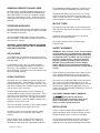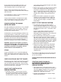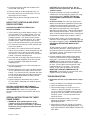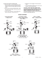
1
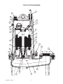
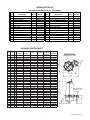
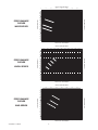
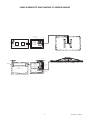
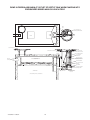
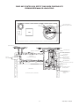
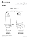
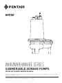
WHR/WHRH/WHRE SERIES SUBMERSIBLE SEWAGE PUMPS INSTALLATION AND SERVICE MANUAL NOTE! To the installer: Please make sure you provide this manual to the owner of the equipment or to the responsible party who maintains the system. Part # 23833A551 | © 2012 Pentair Pump Group, Inc. | 11/08/12 GENERAL DESCRIPTION AND USES The grounded receptacle cannot be used in the wet sump or basin due to DANGER of current leakage. The WHR Series are solids handling pumps that can be used to pump RAW SEWAGE for COMMERCIAL and DOMESTIC use, but are not intended to handle large rags, mop heads or strings. All pumps can be used for normal sewage duty where extra capacity is required. Sealed junction boxes must be used in wet sumps or basins to make connections to motor cord. The AWS-1 control also acts as a sealed junction box for connecting power cord to pump cord. MOTOR TYPES RECESSED IMPELLERS All single phase pump motors are of the permanent split capacitor type that do not require a start switch or start relay. All of the pumps are of the recessed impeller type that provides a clear volute passage for solids as no solids pass through the impeller. Automatic reset overload switches are attached directly to the motor windings. All of the pumps listed can be used to pump septic tank EFFLUENT or GROUND sewage as used in some pressure sewer systems. Three phase pump motors are squirrel cage induction type. WARNING! THESE PUMPS ARE NOT APPROVED FOR, AND SHOULD NOT BE USED IN SWIMMING POOLS OR FOUNTAINS. SAFETY WARNINGS WARNING: Risk of electric shock. Pumps without seal leak detectors are supplied with a grounding conduction and grounding-type attachment plug on the power cord. To reduce the risk of electric shock, be certain that it is connected only to a properly grounded, grounding-type receptacle. DO NOT cut off ground pin or use an adapter fitting. DO NOT use an extension cord with this pump. Entire plug may be cut off if a control panel is used. AIR LOCKING A sewage pump is air locked if water traps air in the pump and it cannot get out, thus preventing the pump from operating. In installations of this type a 1/8" hole should be drilled in the discharge pipe below the check valve. The check valve should be 12 to 18 inches above pump discharge. Do not put check valve directly into pump discharge opening. When wiring this pump follow all local electrical and safety codes and ordinances as well as the most recent National Electric Code (NEC-ANSI/NFPA 70). LEVEL CONTROLS All pumps have a GROUND WIRE that is connected to a screw in the metal motor housing. This wire goes to the receptacle or control box which must be connected to a good outside GROUND such as a metal water pipe or GROUND STAKE driven at least 8 feet into the ground. All pumps must use sealed level control switches for automatic operation. MLC and MFLC controls have sealed switches that are 1 HP rated at 230 volts. ALC and AWS-1 controls have sealed mechanical switches that are rated 2 HP at 230 volts. Simplex single phase pumps can be automatic by attaching MFLC or MLC controls to the pump. These switches have a fixed draw-off level of 8 to 10 inches and can be used up to 1 HP. For higher horsepower ratings two mercury switch (or SMNO) controls with a magnetic starter can be used. CALIFORNIA PROPOSITION 65 WARNING: This product and related accessories contain chemicals known to the State of California to cause cancer, birth defects or other reproductive harm. The ALC and AWS-1 controls can be used for simplex single phase pumps with ratings up to 2 HP. INSTALLATION All duplex systems must use pilot mercury control sensor switches with control box and magnetic starters. Pumps can be installed inside sealed basins with proper venting for either simplex or duplex systems. Simplex or duplex basin systems are available. Plug-in cords can be used on all the single phase pumps without seal leak detector. This cord has a GROUND pin that plugs into a grounded receptacle. It is not recommended that basins be used for raw sewage inside the home, but are for use in office buildings and small industrial buildings and factories. 23833A551 11/08/12 2 If raw sewage must be pumped in the home, use outside basins that connect with pressure sewer mains or gravity sewers, or run to septic tanks. cover, power cord is brought through a split rubber plug in the basin cover. 2.Where 2 float controls are used, the turn-on control is set 3" to 6" above top of motor, and the turnoff control is set about 6" to 8" above bottom of basin. If a high level alarm control is used, it is set about 6" above upper control. If basin depth will not allow these settings, closer spacing can be used. Basins can be used inside the home where extra capacity sump pumps are required for water softeners and wash water. If an inside basin is used, it is usually installed at the time of pouring the concrete floor. 3.Where ALC or AWS-1 (automatic wet systems) controls are used, the displacement weights are set so that turn-on weight is 4" to 6" above top of motor and lower weight is set about 6" above basin bottom. Pumps can be installed in a compartment of septic tanks for pumping to pressure sewer mains, gravity sewers, leach fields, or evaporation mounds. HOW TO START SIMPLEX SYSTEMS PROPER VENTING FOR BASINS INSTALLED INSIDE 1.For single-phase pumps with MLC or MFLC control, plug cords piggyback into receptacle and run water into basin until pump starts. Allow pump to make several on/off cycles. Leave power cord plugged in. All inside sealed basins must have a 2" or 3" vent pipe installed in accordance with local codes. Basins for handling softener water, wash or drainage water do not have to be sealed or vented. If pump runs but does not pump it may be air locked. Unplug cord and crack union in the discharge line, then restart pump. This should vent off any trapped air. Retighten union. Outside basins are usually of fiberglass and from 4 to 8 feet deep and have a sealed cover. Pump is usually installed with a lift-out rail system so that pump can be removed without disturbing the discharge piping. The check valve comes out with pump for servicing. Complete lift-out systems mounted in fiberglass basins are available to meet customer specifications. 2.With 2 float controls turn on power at the control box and run water into basin. When level gets above top control, pump should start and continue to pump until level drops to lower control, stopping pump. Run pump through several cycles. If pump runs but does not pump, check air lock. Leave power on for automatic operation. WARNING: Basin must be vented in accordance with local plumbing codes. These pumps are not designed for and CANNOT be installed in locations classified as hazardous in accordance with the National Electric Code ANSI/NFPA 70. 3.Where ALC or AWS-1 controls are used, plug in cord or turn-on power and run water into basin. When level is about halfway up on upper weight, pump should start and run until level drops until about half the lower weight is above water, stopping pump. PIPING Pumps are fitted with 2" or 3" female threaded pipe flange. Galvanized or PVC plastic pipe can be used. Plastic pipe is preferred for raw sewage or septic tank effluent. For all cases if motor does not start when water level is up, check for proper plug-in or that start switch is on, or if fuse is blown. CHECK VALVES AND SHUT-OFF VALVES ALWAYS HAVE ELECTRICIAN MAKE ELECTRICAL CHECKS. All pumps must have check valves and shut-off valves in the discharge line. Check valves must be flapper type with outside spring or ball type. Shut-off valves can be ball or gate type. Plastic construction for both check or shut-off valves is preferred. STARTING PUMP PIGGYBACK (AUTOMATIC) USING MECHANICAL SWITCH WITH SERIES PLUG – SIMPLEX SYSTEM HOW TO SET CONTROLS FOR SIMPLEX SYSTEMS 1.These pumps have a mechanical (mercury-free) float switch with a 20 ft. cord and a 115 volt or 230 volt series piggyback plug on 1/2 HP with switch mounted to the pump. On 3/4, 1, and 2 HP, it requires 20 ft. cord and 230 volt only. 1.Automatic systems — These systems have the float switches mounted on the pump, so pump is installed in the basin and motor cord is plugged into GROUNDED receptacle. For sealed basin 2.Plug the switch cord plug into a proper voltage, properly grounded outlet. 3 23833A551 11/08/12 CAUTION! Risk of electric shock. Do not remove cord and strain relief. Do not connect conduit to pump. 3.Plug the pump power cord into the back of the switch cord series plug. 4.Tape the cords to the discharge pipe every 12". 2.Three phase pumps are always installed with control boxes having magnetic starters with 3-leg overload protection. DO NOT TRY TO RUN THREE PHASE PUMPS DIRECTLY ACROSS THE LINE. 5.Run water into basin until pump starts. Be sure discharge line valve is open. 6.Allow pump to operate through several on/off cycles. 3.To Connect Pump: Run wire from pump to the bottom of control box or appropriate junction box suitable for enclosing splice connections. A hole must be cut into the control box for the wires. With power to control box off, connect green (ground) line to ground lug. Connect black (power) wires to power lead terminals. Make sure that all wires are inside control box and not in a position to be pinched or shorted when the door is closed. HOW TO SET CONTROLS AND START DUPLEX SYSTEMS CONTROL BOX MUST BE USED ON ALL DUPLEX SYSTEMS 1.4 float controls are used for duplex systems. Set turn-on control 6" to 8" above pumps. Set turnoff control 8" to 10" above bottom of basin. Set override control 6" to 8" above turn-on control. Set high level alarm control about 6" to 8" above override control. Mark all control cords so that they can be connected correctly in the control box. 4.All three phase motors can run either direction. Rotation can be changed by interchanging any two line leads at magnetic starter. BE SURE CIRCUIT BREAKER IS OFF BEFORE MAKING THIS CHANGE. 2.Turn Hand-Off-Auto switches to OFF position and close circuit breaker. To find if rotation is correct, operate pumps and check delivery operation. If flow and head are low (refer to pump curve shown in this manual), the rotation is wrong. With duplex pumps check operation of both pumps. 3.Turn both H-O-A switches to the AUTO position and run water into basin. When level floats up and activates the turn-on switch, one pump should start and run. Pump will continue to run until lower control is exposed, stopping pump. 5.All pump impellers either single or three phase must turn counterclockwise when looking into pump inlet. If uncertain of rotation, TURN OFF POWER and lift pump from basin with cord connected and lay pump on side so impeller can be seen. Turn on power and start pump using hand position of H-O-A switch. Turn on and off fast, so that coast of impeller can be seen. NEVER PUT HAND OR FINGERS ON THE IMPELLER. Interchange any two line leads at the magnetic starter to change rotation. 4.Run water into sump again and when level floats up turn-on control, opposite pump will start and run until level drops exposing lower control, stopping pump. 5.Run this test several times to be sure pumps are alternating properly. 6.To check high level alarm, again turn both switches to OFF and fill basin until level is above the alarm control. Turn switches to AUTO position and alarm buzzer should sound and alarm light should come on. When level drops below the alarm, control buzzer should stop. TROUBLESHOOTING 1.Pump does not run or start when water is up in tank. 7.If pumps operate as described, then set both H-O-A to AUTO and pumps are ready to operate automatically. CAUTION: NEVER WORK ON PUMPS OR CONTROL BOXES UNTIL CIRCUIT BREAKERS ARE TURNED OFF. Always have a qualified electricion make electrical connections and service checks. SPECIAL INSTRUCTIONS FOR THREE PHASE PUMPS 1.WARNING! Only qualified persons shall conduct services and installations of this pump. The pump must be wired by a qualified electrician, using an approved starter box and switching device. 23833A551 11/08/12 4 a.Check for blown fuse or tripped circuit breaker. b.Check for defective level switch. c.Where control panel is used be sure H-O-A switch is in the AUTO position. If it does not run, turn switch to the HAND position and if the pump runs then the trouble is in the automatic electrical system. Have an electrician make electrical checks. d.Check for burned-out motor. Occasionally lightning can damage a motor even with lightning protection. e.Where plug-in cords are used be sure contact blades are clean and making good contact. DO NOT USE PLUG-IN CORDS INSIDE A BASIN OR WET WELL. 2.Pump runs but does not deliver flow. a.Check for airlock. Start and stop pump several times. If this does not help it may be necessary to loosen a union in the discharge line to relieve airlock. b.Check valve may be installed backward. Check flow arrow on valve body. Check shut-off valve. It may be closed. c.Check vertical elevation. It may be higher than pump can develop. (See pump curves.) d.Pump inlet may be plugged. Remove pump to check. e.Level control ball or weight may be stuck on side of basin. Be sure it floats freely. CAUTION: ALWAYS UNPLUG POWER CORDS OR TURN OFF ALL MAIN AND BRANCH CIRCUIT BREAKERS BEFORE DOING ANY WORK ON THE PUMP. If control panel is remote from pump, disconnect lead wires to motor so that no one can turn the circuit breaker back on. WIRING DIAGRAMS 115V, 200V or 230V 1 Phase, P.S.C. 115V, 200V or 230V 1 Phase, Single Voltage P.S.C. Motor Black White Red Black Green 575V – 3 Phase 200V – 3 Phase (3 HP) White White or Yellow Green Black Green Black White Ground Black Ground Brown Red Seal Leak Electrode Brown Ground DOUBLE SEAL PUMPS WITH SEAL LEAK PROBE (RED CONDUCTOR IN POWER CORD IS FOR SEAL LEAK PROBE) Green Black Black White Green Red Ground White Red Ground 230V – 3 Phase 208V – 3 Phase (1–2 HP) 460V – 3 Phase 5 23833A551 11/08/12 TYPICAL SECTION DRAWING 1 27 26 25 2 24 3 23 22 4 21 5 6 7 20 8 9 19 10 11 18 9 12 15 16 17 23833A551 11/08/12 13 14 6 REPAIR PARTS LIST Ref. No. 1 2 3 4 5&6 6A 7 8 9 10 10 11 12 13 SINGLE SEAL REPAIR PARTS LIST WHRH SERIES No. Ref. Req'd Part No. No. Description Description Cord, Power 1 See Chart 14 Impeller, DI (std. series) Housing, motor 1 25327D000 15 Screw, Machine #10 x 3/8 Washer, Bearing 1 19331A005 16 Sealant ( Grade 271 Loctite®) Oil, Transformer (5 gal.) .8-1 gal 11009A006 17 Washer, Impeller Retainer Stator, Rotor shaft with shell 1 See Chart 18 Gasket, tetraseal,7 x6-3/4 x1/8 Connectors (3 ph only) 3-6 15781A001 19 Bearing, ball, lower S eal, s haft 1 25370A 000 20 B earing, ball, upper Plate, brg & seal 1 25367D000 21 Clip, capacitor (1 ph only) Screw, cap, 5/16 x 1-1/4 8 19100A012 22 Capacitor (1 ph only) Flange, 2" CI 1 002080002 23 Plug, 1/4" pipe Flange, 3" CI Alternate 1 002070002 24 Washer, 3/32" Thk. Screw, cap, 1/2-13 x 1-1/2 2 19103A043 25 Gasket, rubber Gasket, rubber 1 003240011 26 Washer, 1/32" Thk. Case, volute 1 27195E000 27 Nut, cord plug,solid No. Req'd 1 1 1 1 1 1 1 1 1 1 1 1 1 1 Part No. See Chart 06106A042 14550A001 05030A242 05014A181 08565A022 08565A 013 See Chart See Chart 05022A009 05030A235 05014A193 05030A234 25341A002 Unit manufactured prior to Aug-2007 contact factory for repair parts VARIABLE PARTS CHART HP Volts ph 1/2 1/2 1/2 1/2 1/2 1/2 1/2 3/4 3/4 3/4 3/4 3/4 3/4 3/4 1 1 1 1 1 1 1-1/2 1-1/2 1-1/2 1-1/2 1-1/2 1-1/2 2 2 2 2 2 2 115 208 230 208 230 460 575 115 208 230 208 230 460 575 208 230 208 230 460 575 208 230 208 230 460 575 208 230 208 230 460 575 1 1 1 3 3 3 3 1 1 1 3 3 3 3 1 1 3 3 3 3 1 1 3 3 3 3 1 1 3 3 3 3 Power Cord w/Plug Power Cord No Plug 25338B004 25338B006 25338B006 25338B006 25338B003 25338B003 25338B003 25338B003 25338B002 25338B002 25338B002 25338B003 25338B003 25338B003 25338B003 25338B002 25338B002 25338B003 25338B003 25338B003 25338B003 25338B002 25338B002 25338B003 25338B003 25338B003 25338B003 25338B009 25338B009 25338B008 25338B008 25338B003 25338B003 25338B005 25338B000 25338B001 25338B001 25338B001 Cap. Cap. Clip 23839A000 23839A000 23839A000 20333A006 20333A006 20333A006 23839A000 23839A000 23839A000 20333A006 20333A006 20333A006 23838A000 23838A000 20333A004 20333A004 23838A000 23838A000 20333A004 20333A004 23839A000 26520A000 20333A006 20333A006 Stator Rotor and Shaft Assembly 25484D100 25484D101 25484D101 25484D102 25484D102 25484D102 25484D103 25484D100 25484D101 25484D101 25484D102 25484D102 25484D102 25484D103 25484D104 25484D105 25484D106 25484D106 25484D106 25484D107 25484D104 25484D105 25484D106 25484D106 25484D106 25484D107 25484D108 25484D109 25484D110 25484D111 25484D111 25484D112 7 WHRH Impeller DI 27194C003 27194C003 27194C003 27194C003 27194C003 27194C003 27194C003 DIMENSIONS [dimensions in mm] 215/18" [75] 103/8" [264] 61/4" [159] 131/4" [337] 27194C002 27194C002 27194C002 27194C002 27194C002 27194C002 27194C001 27194C001 27194C001 27194C001 27194C001 27194C001 27194C010 27194C010 27194C010 27194C010 27194C010 27194C010 2" NPT Flanged Discharge, 3" NPT Optional 193/4" [502] 21/8" [54] 65/8" [168] 23833A551 11/08/12 CAPACITY LITERS PER MINUTE 0 50 100 150 200 250 300 350 140 27 130 120 WHRE SERIES TOTAL HEAD IN FEET PERFORMANCE CURVES WHR E20 –2 100 90 21 HOR SEP OW ER 18 80 WHR E10 –1 HOR SEP OW ER WHR E5 – 1/2 HOR SEP OW ER 70 60 50 15 12 40 TOTAL HEAD IN METERS 24 110 9 30 20 6 10 0 3 0 10 20 30 40 50 60 70 80 90 100 CAPACITY GALLONS PER MINUTE CAPACITY LITERS PER MINUTE 0 100 200 300 400 500 600 700 800 900 1000 1100 70 20 65 PERFORMANCE CURVES WHRH SERIES TOTAL HEAD IN FEET 55 50 W HR 15 H 45 W HR 20 H 15 W HR 10 H 40 35 10 WH R5 H 30 25 TOTAL HEAD IN METERS 60 20 5 15 10 5 0 0 30 60 90 120 150 180 210 240 270 300 CAPACITY GALLONS PER MINUTE CAPACITY LITERS PER MINUTE 0 100 200 300 400 500 600 700 34 10 32 WH R1 0– PERFORMANCE CURVES WHR SERIES TOTAL HEAD IN FEET 28 26 WH R7 – 24 22 WH R5 – 20 18 9 1H OR SE PO WE R 8 3/4 HO RS EP OW ER 7 1/2 HO RS EP OW ER 6 5 16 14 4 12 10 3 8 6 2 0 20 40 60 80 100 120 140 CAPACITY GALLONS PER MINUTE 23833A551 11/08/12 8 160 180 200 TOTAL HEAD IN METERS 30 PUMP IN SEPARATE TANK PUMPING TO SEEPAGE MOUND ALARM AND POWER CORDS TO POWER SOURCE AWS-1 CONTROL AWS-1 CONTROL MOUND TYPE SEEPAGE BED STORAGE CAPACITY IN CASE OF PUMP OR POWER FAILURE SEWER LINE FROM HOUSE FLCW ALARM CONTROL SCUM TURN ON LEVEL SEPTIC TANK CAPACITY REQUIRED BY LOCAL CODES LIFT-OUT GUIDE RAIL TURN OFF LEVEL EFFLUENT AND PUMP TANK SEAL FITTING SLUDGE EFFLUENT PUMP SLUDGE 9 23833A551 11/08/12 PUMP IN FIBERGLASS BASIN AT OUTLET OF SEPTIC TANK WHEN PUMPING INTO PRESSURIZED SEWER MAIN OR LEACH FIELD ALARM CABLE POWER CABLE AWS-1 CONTROL MOUNTS ON BRACKET. ACCESSIBLE FOR SERVICE SLUDGE CLEAN OUT TILE BURIED CABLE TO POWER SUPPLY AWS-1 CONNECTION BOX AND SEALED LEVEL CONTROL VENT PIPE 24” DIA. FIBERGLASS BASIN FLCW - HIGH WATER ALARM CONTROL RAIL SYSTEM - PUMP CAN BE LIFTED OUT WITHOUT DISCONNECTING ANY PIPING STORAGE CAPACITY IN CASE OF POWER OR PUMP FAILURE WASTE LINE FROM HOUSE LEVEL CONTROL WEIGHTS CHECK VALVE AND LIFT-OFFF SEAL FITTING SCUM 4” TURN-ON LEVEL PUMP OFF CAPACITY SHUT-OFF VALVE TURN-OFF LEVEL DISCHARGE TO LEACH FIELD OR PRESSURE SEWER 4” CONNECTING PIPE CLARIFIED EFFLUENT SEPTIC TANK SIZE ACCORDING TO CODE REGULATIONS SLUDGE 23833A551 11/08/12 10 EFFLUENT PUMP AVAILABLE FOR HEADS OVER 100 FT. PUMP AND CONTROLS IN SEPTIC TANK WHEN PUMPING INTO PRESSURIZED MAIN OR LEACH FIELD ALARM CABLE POWER CABLE AWS-1 CONTROL MOUNTS ON BRACKET. ACCESSIBLE FOR SERVICE SLUDGE CLEAN OUT TILE 24” DIA. FIBERGLASS BASIN BURIED CABLE TO POWER SUPPLY AWS-1 CONNECTION BOX AND SEALED LEVEL CONTROL FLCW - HIGH WATER ALARM CONTROL STORAGE CAPACITY IN CASE OF POWER OR PUMP FAILURE WASTE LINE FROM HOUSE RAIL SYSTEM - PUMP CAN BE LIFTED OUT WITHOUT DISCONNECTING ANY PIPING SCUM 4” LEVEL CONTROL WEIGHTS TURN-ON LEVEL PUMP OFF CAPACITY TURN-OFF LEVEL CHECK VALVE AND LIFT-OFFF SEAL FITTING SHUT-OFF VALVE DISCHARGE TO LEACH FIELD OR PRESSURE SEWER CLARIFIED EFFLUENT EFFLUENT PUMP SUPPORTED BY RAIL SYSTEM AVAILABLE FOR HEADS OVER 100 FT. SEPTIC TANK SIZE ACCORDING TO CODE REGULATIONS SLUDGE 11 23833A551 11/08/12 STANDARD LIMITED WARRANTY Pentair Myers® warrants its products against defects in material and workmanship for a period of 12 months from the date of shipment from Pentair Myers or 18 months from the manufacturing date, whichever occurs first – provided that such products are used in compliance with the requirements of the Pentair Myers catalog and technical manuals for use in pumping raw sewage, municipal wastewater or similar, abrasive-free, noncorrosive liquids. During the warranty period and subject to the conditions set forth, Pentair Myers, at its discretion, will repair or replace to the original user, the parts that prove defective in materials and workmanship. Pentair Myers reserves the right to change or improve its products or any portions thereof without being obligated to provide such a change or improvement for prior sold and/or shipped units. Start-up reports and electrical schematics may be required to support warranty claims. Submit at the time of startup through the Pentair Myers website: http://forms.pentairliterature.com/startupform/startupform.asp?type=m. Warranty is effective only if Pentair Myers authorized control panels are used. All seal fail and heat sensing devices must be hooked up, functional and monitored or this warranty will be void. Pentair Myers will cover only the lower seal and labor thereof for all dual seal pumps. Under no circumstance will Pentair Myers be responsible for the cost of field labor, travel expenses, rented equipment, removal/reinstallation costs or freight expenses to and from the factory or an authorized Pentair Myers service facility. This limited warranty will not apply: (a) to defects or malfunctions resulting from failure to properly install, operate or maintain the unit in accordance with the printed instructions provided; (b) to failures resulting from abuse, accident or negligence; (c) to normal maintenance services and parts used in connection with such service; (d) to units that are not installed in accordance with applicable local codes, ordinances and good trade practices; (e) if the unit is moved from its original installation location; (f) if unit is used for purposes other than for what it is designed and manufactured; (g) to any unit that has been repaired or altered by anyone other than Pentair Myers or an authorized Pentair Myers service provider; (h) to any unit that has been repaired using non factory specified/OEM parts. Warranty Exclusions: Pentair MYERS MAKES NO EXPRESS OR IMPLIED WARRANTIES THAT EXTEND BEYOND THE DESCRIPTION ON THE FACE HEREOF. Pentair MYERS SPECIFICALLY DISCLAIMS THE IMPLIED WARRANTIES OF MERCHANTABILITY AND FITNESS FOR ANY PARTICULAR PURPOSE. Liability Limitation: IN NO EVENT SHALL Pentair MYERS BE LIABLE OR RESPONSIBLE FOR CONSEQUENTIAL, INCIDENTAL OR SPECIAL DAMAGES RESULTING FROM OR RELATED IN ANY MANNER TO ANY Pentair MYERS PRODUCT OR PARTS THEREOF. PERSONAL INJURY AND/OR PROPERTY DAMAGE MAY RESULT FROM IMPROPER INSTALLATION. Pentair MYERS DISCLAIMS ALL LIABILITY, INCLUDING LIABILITY UNDER THIS WARRANTY, FOR IMPROPER INSTALLATION. Pentair MYERS RECOMMENDS INSTALLATION BY PROFESSIONALS. Some states do not permit some or all of the above warranty limitations or the exclusion or limitation of incidental or consequential damages and therefore such limitations may not apply to you. No warranties or representations at any time made by any representatives of Pentair Myers shall vary or expand the provision hereof. 1101 MYERS PARKWAY 490 Pinebush Road, Unit #4 ASHLAND, OHIO, USA 44805 CAMBRIDGE, ONTARIO, CANADA N1T 0A5 419-289-1144800-363-PUMP WWW.FEMYERS.COM Warranty Rev. 12/13