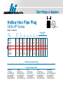
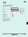
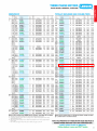
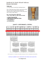
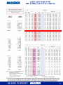
1
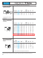
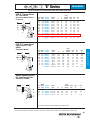
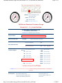
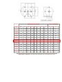
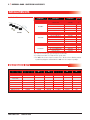
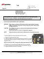
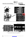
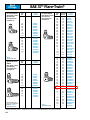
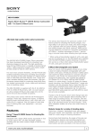
OASIS CAR WASH Air Compressor Manual Model #: C-10448 Manufactured by John Henry Foster Co iiiiiiiiiiiiiiiiiiiiii ‘E’ Series Hose Ends Use Hose H00905, 06, 08; H209; H243; H265; H275; H285; H435; H436 Flareless Tube Rigid (With Nut and Sleeve) A E F A Hose Cut-Off Factor† Hole Dia. Hex E Hex F 1.88 1.78 1.82 2.08 1.00 .88 .88 1.06 .22 .23 .27 .38 5/8 9/16 5/8 13/16 11/16 5/8 11/16 7/8 Thread Size A Hose Cut-Off Factor† Hole Dia. Hex E Hex F 03E-604 a 04E-604 a 04E-605 a 04E-606 c 05E-605 a 05E-406 b 05E-606 c 06E-406 b 06E-606 c 06E-608 a 08E-608 a 08E-610 a 12E-412 b 12E-612 c 16E-616 c 7/16-20 7/16-20 1/2-20 9/16-18 1/2-20 5/8-18 9/16-18 5/8-18 9/16-18 3/4-16 3/4-16 7/8-14 1-1/16–14 1-1/16–12 1-5/16–12 1.89 1.92 2.00 2.06 2.07 2.03 2.12 2.06 2.19 2.30 2.39 2.51 2.76 2.76 3.05 1.00 1.13 1.19 1.25 1.19 1.13 1.19 1.13 1.25 1.38 1.38 1.50 1.56 1.56 1.75 .09 .16 .16 .16 .22 .22 .22 .27 .27 .27 .38 .38 .61 .61 .84 7/16 7/16 1/2 9/16 1/2 9/16 9/16 9/16 9/16 3/4 3/4 7/8 1 1 1-1/4 9/16 9/16 5/8 11/16 5/8 3/4 11/16 3/4 11/16 7/8 7/8 1 1-1/4 1-1/4 1-1/2 BSPP Hose Pipe I.D. Size Catalog Number Thread Size A Hose Cut-Off Factor† Hole Dia. Dia. E Hex F 3/16 1/4 3/8 3/8 1/2 1/2 3/4 1 03E-354 04E-354 06E-356 06E-358 08E-358 08E-360 12E-362 16E-366 G-1/4-19* G-1/4-19* G-3/8-19* G-1/2-14* G-1/2-14* G-5/8-14* G-3/4-14* G-1-11* 2.01 1.88 2.09 2.47 2.56 2.70 2.94 3.38 1.19 1.00 1.13 1.50 1.50 1.63 1.69 2.00 .16 .16 .27 .27 .39 .39 .61 .84 9/16 9/16 3/4 13/16 13/16 7/8 1 1-1/4 11/16 11/16 7/8 1 1 1-3/16 1-1/4 1-1/2 Hose Tube I.D. Size Catalog Number Thread Size 5/16 3/8 3/8 1/2 3/8 5/16 3/8 1/2 05E-756 06E-755 06E-756 08E-758 9/16-18 1/2-20 9/16-18 3/4-16 Hose Tube I.D. Size Catalog Number (For replacement Nuts and Sleeves, see page 190). SAE 37° Female Swivel (Exceptions Noted, Refer to Footnotes) A E F British Standard (BSPP) 60° Cone Female Pipe Swivel A E F 3/16 1/4 1/4 1/4 5/16 5/16 5/16 3/8 3/8 3/8 1/2 1/2 3/4 3/4 1 1/4 1/4 5/16 3/8 5/16 3/8 3/8 3/8 3/8 1/2 1/2 5/8 3/4 3/4 1 1/4 1/4 3/8 1/2 1/2 5/8 3/4 1 *G As Part of Thread Size is ISO Designation for Parallel Thread. †To determine the correct length of hose, subtract the cut-off factor for each end fitting from the overall length of assembly. a Swivel nuts are universal – both SAE 37° and 45° connections. b SAE 45° flare connection only. c SAE 37° flare connection only. 58 iiiiiiiiiiiiiiiiiiiiii ‘E’ Series Hose Ends Use Hose H00905, 06, 08; H209; H243; H265; H275; H285; H435; H436 SAE 37° Female Swivel 90° Tube Elbow (Exceptions Noted, Refer to Footnotes) A B E F Hose Tube Catalog I.D. Size Number 1/4 1/4 5/16 5/16 3/8 3/8 3/8 1/2 1/2 3/4 3/4 1 1/4 5/16 5/16 3/8 3/8 3/8 1/2 1/2 5/8 3/4 1 1 Thread Size 04E-664 a 7/16-20 04E-665 a 1/2-20 05E-665 a 1/2-20 05E-666 c 9/16-18 06E-466 b 5/8-18 06E-666 c 9/16-18 06E-668 a 3/4-16 08E-668 a 3/4-16 08E-670 a 7/8-14 12E-672 c 1-1/16–12 12E-676 c 1-5/16–12 16E-676 c 1-5/16–12 A B Hose Cut-Off Factor† 2.27 2.51 2.58 2.57 2.72 2.72 2.83 2.82 3.34 3.70 4.51 4.39 .68 .77 .77 .85 .85 .85 1.09 1.09 1.23 1.82 2.15 2.14 1.44 1.63 1.63 1.62 1.75 1.75 1.88 1.75 2.31 2.50 3.19 3.00 Hole Dia. .15 .16 .21 .22 .24 .24 .27 .33 .39 .59 .76 .83 Hex E Hex F 7/16 9/16 7/16 5/8 9/16 5/8 9/16 11/16 5/8 3/4 5/8 11/16 5/8 7/8 3/4 7/8 3/4 1 1 1-1/4 1-1/4 1-1/2 1-1/4 1-1/2 SAE 37° Female Swivel Long Drop 90° Tube Elbow (Exceptions Noted) Hose Tube Catalog I.D. Size Number Thread Size A 1/4 1/4 1/4 5/16 04E-645 a 5/16 3/8 05E-646 c 3/8 3/8 06E-646 c 3/8 1/2 06E-648 a 1/2 1/2 08E-648 a 1/2 5/8 08E-650 a 3/4 3/4 12E-652 c 1 1 16E-656 c 7/16-20 1/2-20 9/16-18 9/16-18 3/4-16 3/4-16 7/8-14 1-1/16–12 1-5/16–12 2.27 2.51 2.63 2.72 2.83 2.92 2.96 3.74 4.36 BSPP Hose Pipe Catalog I.D. Size Number Thread Size A G-1/4-19* G-3/8-19* G-1/2-14* G-3/4-14* 2.89 2.96 2.95 3.83 A 04E-644 a E B B Hose Cut-Off Factor† Hole Dia. Hex E Hex F 1.80 1.80 2.18 2.18 2.43 2.43 2.57 3.73 4.33 1.42 1.63 1.69 1.75 1.88 1.88 1.94 2.50 3.00 .15 .16 .22 .24 .27 .33 .39 .58 .83 7/16 7/16 9/16 5/8 5/8 3/4 3/4 1 1-1/4 9/16 5/8 11/16 11/16 7/8 7/8 1 1-1/4 1-1/2 F British Standard (BSPP) 60° Cone Female Pipe Swivel 90° Elbow A B E 1/4 3/8 1/2 3/4 1/4 3/8 1/2 3/4 04E-74P 06E-76P 08E-78P 12E-82P B Hose Cut-Off Factor† Hole Dia. Hex E Hex F 1.50 1.66 1.73 2.43 2.06 2.00 1.88 2.61 .16 .27 .37 .61 7/16 5/8 3/4 1 3/4 7/8 1 1-1/4 F *G As Part of Thread Size is ISO Designation for Parallel Thread. †To determine the correct length of hose, subtract the cut-off factor for each end fitting from the overall length of assembly. a Swivel nuts are universal – both SAE 37° and 45° connections. b SAE 45° flare connection only. c SAE 37° flare connection only. 61 H O S E E N D S NOSHOK Pressure Gauge 100 Series Model 110 2 1/2 Inch Dial Size Order Info Page 1 of 2 Address: 1010 West Bagley Road Berea, OH 44017 Phone: 440-243-0888 Fax: 440-243-3472 E-mail: [email protected] 100 Series Standard Pressure Gauge Model 110 - 2 ½ Inch Dial Size ORDERING INFORMATION For Regularly Stocked Items (Contact Us for additional gauge offerings) Size and Model 25-110 NPT Connection Size 1/4" NPT 2 ½ Inch Dial Size - Model 110 Brass Center Back Connection Outer Scale Options: psi Inner Scale Options: kPa Dual Scale Dial Units Pressure Ranges 30" Vac 30" Hg Vacuum to 0 psi bar kg/cm² 400 0 psi to 400 psi² 15 0 psi to 15 psi 600 0 psi to 600 psi² 30 0 psi to 30 psi 1,000 0 psi to 1,000 psi¹ 60 0 psi to 60 psi 1,500 0 psi to 1,500 psi² 100 0 psi to 100 psi 2,000 0 psi to 2,000 psi¹ 160 0 psi to 160 psi 3,000 0 psi to 3,000 psi² 200 0 psi to 100 psi 5,000 0 psi to 5,000 psi² 300 0 psi to 300 psi 6,000 0 psi to 6,000 psi¹ ¹ This Range is Regularly Stocked in psi-kPa Only ² This Range is Not Regularly Stocked in psi-bar Contact Us with your requirements for additional Pressure Range, Dial Scale Unit and Connection availability Stock Options Black Plastic Adapter Ring Instrument Glass Lens Chrome Plated Steel Adapter Ring Laminated Safety Glass Lens Polished 304 Stainless Steel Bezel Lexan Lens http://www.noshok.com/pg/100series/model110/order_info3.html 1/5/2007 NOSHOK Pressure Gauge 100 Series Model 110 2 1/2 Inch Dial Size Order Info Flat-Sided ABS Case Panel Mount Clamps w/Screws Black Painted Steel Case Press Fit Orifices Black Painted Steel Case w/Blow-Out Cintered Press-Fit Orifices 304 Stainless Steel Case Threaded Orifices Chrome Plated Steel Case Adjustable Pointer 10-32 UNF 2B Connection Maximum Indicating Pointer 1/4" NPT x 1/4" BSP Brass Adapter Connection Set Pointer Sealing Gasket for BSP Adapter Connection Certificate of Conformance Black Painted Steel Cover Ring Certified Calibration 304 Stainless Steel Cover Ring Cleaning for Oxygen Services Polished Chrome Plated Steel Cover Ring Rubber Case Protector Black Painted Steel Front Flange - ABS Case NOSHOK Laboratory Services Chrome Plated Steel Front Flange - ABS Case Silicone Dampened Movements Page 2 of 2 Contact Us with your requirements for additional Non-Stock Option and Special Option availability Accessories Piston Type Pressure Snubbers Pigtail Steam Syphons Diaphragm Seals Print this Page Go Back http://www.noshok.com/pg/100series/model110/order_info3.html 1/5/2007 Brass Fittings Compression Tube O.D. E Tube Stop Depth H H1 (Long Nut) 1/8 3/16 1/4 5/16 3/8 1/2 5/8 3/4 .19 .22 .25 .28 .31 .38 .38 .44 .23 .25 .29 .30 .27 .42 .42 .49 – .47 .56 .66 .70 .88 .92 1.18 NOTE: H and H1 are hand tight. Tube Support for Plastic Tubing D A B C Use only with PT200 and PT240 Tubing. * For Tubing with .126 I.D./.062 wall thickness. Tube O.D. Catalog Number Dia. A Dia. B Dia. Length C D 1/4 1/4 5/16 3/8 1/2 5/8 3/4 1 2030x4* 2030x44** 2030x5 2030x6 2030x8 2030x10 2030x12 2030x16 1/8 11/64 3/16 1/4 3/8 1/2 9/16 3/4 3/32 9/64 5/32 7/32 11/32 29/64 33/64 45/64 11/64 19/32 7/32 17/32 15/64 5/8 11/32 41/64 7/16 13/16 35/64 13/16 11/16 1-1/32 51/64 1-1/4 Tube O.D. Catalog Number D F L 1/8 3/16 1/4 5/16 3/8 7/16 1/2 5/8 3/4 1 60x2 60x3 60x4 60x5 60x6 60x7 60x8 60x10 60x12 60x16 .13 .19 .26 .32 .38 .44 .51 .63 .76 1.02 .19 .27 .34 .41 .47 .53 .59 .72 .88 1.17 .19 .22 .25 .25 .25 .31 .38 .38 .44 .56 Tube O.D. Catalog Number Hex C D L 1/8 3/16 1/4 5/16 3/8 7/16 1/2 5/8 3/4 61x2 61x3 61x4 61x5 61x6 61x7 61x8 61x10 61x12 3/8 7/16 1/2 9/16 5/8 11/16 13/16 15/16 1-3/16 .13 .19 .26 .32 .38 .44 .51 .63 .76 .38 .41 .44 .44 47 .50 .62 .62 69 ** For tubing with .170 I.D./.040 wall thickness. Compression Sleeve (Ref. SAE No. 060115) L D F Nut (Ref. SAE No. 060110) L C D MTO - Made To Order 48 Brass Fittings Compression Long Nut Tube O.D. Catalog Number Hex C D L 3/16 1/4 5/16 3/8 1/2 5/8 3/4 1 1611x3 1611x4 1611x5 1611x6 1611x8 1611x10 1611x12 1611x16 7/16 9/16 5/8 11/16 13/16 15/16 1-1/8 1-3/8 .193 .260 .320 .380 .510 .637 .760 1.020 .62 .75 .84 .88 1.06 1.08 1.38 1.59 Tube O.D. Catalog Number Hex C L Thread Size 1/4 5/16 3/8 1/2 0102x4 0102x5 0102x6 0102x8 9/16 5/8 11/16 15/16 Tube O.D. Catalog Number Hex C D L 1/8 3/16 1/4 5/16 3/8 1/2 5/8 3/4 62x2 62x3 62x4 62x5 62x6 62x8 62x10 62x12 5/16 3/8 7/16 1/2 9/16 11/16 13/16 1 .094 .125 .188 .250 .312 .406 .500 .562 .66 .76 .79 .88 .97 1.10 1.25 1.44 Tube Male Pipe O.D. Thread Catalog Number Hex C D D1 Opt. L (Ref. SAE No. 060102BA) Assembly with long nut 168x *Available only as assembly with long nut. 1/8 1/8 3/16 3/16 1/4 1/4 5/16 5/16 3/8 3/8 3/8 3/8 7/16 1/2 1/2 1/2 5/8 3/4 3/4 1 68x2x1 68x2 68x3 68x3x4 68x4 68x4x4 68x5 68x5x4 68x6x2 68x6 68x6x6 68x6x8 68x7 68x8x4 68x8 68x8x8 68x10 68x12 68x12x12 168x16* 3/8 7/16 7/16 9/16 7/16 9/16 1/2 9/16 9/16 9/16 11/16 7/8 5/8 11/16 11/16 7/8 7/8 1 1-1/16 1-3/8 .094 .094 .125 .125 .188 .188 .250 .250 .312 .312 .312 .312 .312 .406 .406 .406 .500 .562 .562 .875 – .094 .125 .125 .188 .312 .234 .250 .250 .312 .312 .562 .312 .281 .406 .406 .500 .562 .875 – .78 .78 .84 1.03 .88 1.06 .91 1.09 .97 1.17 1.16 1.34 1.19 1.22 1.22 1.41 1.50 1.62 1.62 2.00 L C D Bulkhead Nut L Used on 74x Bulkhead Unions. Ref. page 50. (Ref. SAE No. 060101BA) L D C Male Connector L D D1 C B R A S S C Union Assembly with long nut 162x .25 7/16–24 .25 1/2–24 .25 9/16–24 .38 11/16–20 1/16 1/8 1/8 1/4 1/8 1/4 1/8 1/4 1/8 1/4 3/8 1/2 1/4 1/4 3/8 1/2 1/2 1/2 3/4 1 MTO - Made To Order 49 BOSTON WEATHERHEAD ™ Brass Fittings Air Brake – Copper Tubing Bulkhead Coupling (Brass) L Fem. Pipe Thread Catalog Thread Thread Size B Hex C Hex C1 D I L 1/4 1/4 3/8 1/2 1344 1345 1346 1351 Male Fem. Pipe Pipe Thread Thread Catalog Number Thread Size B Hex Hex C1 C 1340 1341 3/4–16 3/4–16 1-1/4 15/16 .312 1.13 2.16 1-1/4 15/16 .312 1.53 2.53 I C D Pipe Thread Pipe Thread Thread Size-B 3/4–16 1 15/16 .422 1.25 1.50 3/4–16 1 15/16 .422 .69 .94 1–14 1-1/8 1-3/8 .563 1.06 1.31 1-1/8–14 1-1/4 1-3/8 .703 1.19 1.50 G Bulkhead Coupling (Brass) L C I Pipe Thread 1/2 1/2 1/4 1/4 D I L Thread Size-B Pipe Thread G Bulkhead Coupling (Brass) Male Fem. Pipe Pipe Thread Thread L I C Thread Size-B Catalog Number Thread Size B 1342 1343 1–14 1–14 Male Pipe Thread Catalog Number D L 1/4 W15310 .188 1.56 Male Fem. Pipe Pipe Thread Thread Catalog Number Hex C Hex C1 D L 1/4 W20332 5/8 3/4 .218 1.81 Male Pipe Thread Catalog Number Hex C L 1/4 145 9/16 1.00 1/2 1/2 1/4 1/4 Hex C Hex C1 1-1/4 1-3/8 1-1/4 1-3/8 D I L .375 1.88 2.94 .375 2.88 3.94 Pipe Thread Pipe Thread G Draincock L D L Shut Off Valve D C1 C Rating: 125 psi with one 1/4" bubble in 5 seconds permissible key leakage. 1/4 External Seat Draincock C L 103 BOSTON WEATHERHEAD ™ B R A S S Brass Fittings Pipe Cap L C *PTF Short Thread Slotted Plug L E *PTF Short Thread Square Head Plug L F C *PTF Short Thread Hex Head Plug L C F * PTF Short Thread ** PTF Special Short Thread Hex Socket Plug L Socket Hex Adapter Catalog Number Hex C L 1/8* 1/4* 3/8* 3129x2 3129x4 3129x6 9/16 11/16 13/16 .50 .59 .68 Male Pipe Thread Catalog Number E L 1/8* 1/4* 3/8* 3150x2 3150x4 3150x6 .05 .08 .09 .28 .42 .43 Male Pipe Thread Catalog Number Square C F L 1/8* 1/4* 3/8* 1/2* 3/4* 3151x2 3151x4 3151x6 3151x8 3151x12 .28 .37 .43 .56 .62 .24 .29 .32 .39 .43 .58 .74 .82 .99 1.12 Male Pipe Thread Catalog Number Hex C F L 1/16 1/8* 1/4* 3/8* 1/2* 3/4** 3152x1 3152x2 3152x4 3152x6 3152x8 3152x12 3/8 7/16 9/16 11/16 7/8 1-1/16 .18 .19 .18 .22 .22 .25 .56 .57 .62 .72 .78 .88 Male Pipe Thread Catalog Number Socket Hex L 1/16 1/8 1/4 3/8 1/2 3153x1 3153x2 3153x4 3153x6 3153x8 5/32 3/16 1/4 5/16 3/8 .260 .270 .410 .410 .540 Hex C D L 1/2 9/16 3/4 3/4 7/8 7/8 1-1/16 1-1/4 1-1/4 .125 .219 .219 .312 .312 .438 .438 .438 .562 .88 .88 1.06 1.25 1.25 1.25 1.47 1.59 1.69 Fem. Male Pipe Pipe Thread Thread (Ref. SAE No. 130139) L C D Fem. Pipe Thread 1/8 1/8 1/4 1/4 3/8 3/8 1/2 3/4 3/4 1/16 1/8 1/8 1/4 1/4 3/8 3/8 3/8 1/2 Catalog Number 3200x2x1 3200x2 3200x4x2 3200x4 3200x6x4 3200x6 3200x8x6 3200x12x6 3200x12x8 B R A S S MTO - Made To Order 107 BOSTON WEATHERHEAD ™ Brass Fittings Pipe Male Fem. Pipe Pipe Thread Thread Bushing (Ref. SAE No. 130140) Hex C 3220x4x2 3220x6x2 3220x6x4 3220x8x2 3220x8x4 3220x8x6 3220x12x6 3220x12x8 5/8 11/16 11/16 7/8 7/8 7/8 1-1/8 1-1/8 .339 .328 .438 .530** .438** .562 .562 .703 .59 .75 .69 .75 .75 .75 .88 .88 Fem. Pipe Thread Catalog Number Hex C D L 1/8* 1/4* 3/8 1/2 3250x2 3250x4 3250x6 3250x8 7/8 1-1/16 1-5/16 1-9/16 .339 .438 .560 .703 .97 1.31 1.66 1.81 1/4* 3/8 3/8* 1/2* 1/2* 1/2* 3/4* 3/4* L D *PTF Short Thread **Optional Counterbore Catalog Number C 1/8 1/8 1/4 1/8 1/4 3/8 3/8 1/2 DL L Union L C D *PTF Short Thread Coupling (Ref. SAE No. 130138) L C D Reducer Coupling L C D Hex Nipple D L 1/16 1/8 1/4 3/8 1/2 3/4 3300x1 3300x2 3300x4 3300x6 3300x8 3300x12 7/16 9/16 3/4 7/8 1-1/16 1-1/4 .339 .339 .438 .578 .703 .906 .75 .75 1.12 1.12 1.50 1.53 Catalog Number Hex C D L 3300x4x2 3300x6x2 3300x6x4 3300x8x6 3/4 7/8 7/8 1-1/16 .339 .339 .438 .562 .96 .94 1.16 1.38 Catalog Number Hex C D D1 L 3325x1 3325x2 3325x2x1 3325x4x2 3325x4 3325x6x2 3325x6x4 3325x6 3325x8 3325x12 3/8 7/16 7/16 9/16 9/16 11/16 11/16 11/16 7/8 1-1/16 .125 .219 .230 .219 .312 .219 .312 .438 .562 .750 .125 .219 .156 .219* .312 .438 .438 .438 .562 .750 .978 .97 .955 1.19 1.38 1.22 1.41 1.41 1.81 1.94 1/4 3/8 3/8 1/2 1/8 1/8 1/4 3/8 Male Male Pipe Pipe Thread Thread A A1 (Ref. SAE No. 130137) L C D1 D A 108 Hex C A1 A MTO - Made To Order Catalog Number Fem. Fem. Pipe Pipe Thread Thread A A1 (Ref. SAE No. 130138) *Optional Counterbore .312 Fem. Pipe Thread A1 1/16 1/8 1/8 1/4 1/4 3/8 3/8 3/8 1/2 3/4 1/16 1/8 1/16 1/8 1/4 1/8 1/4 3/8 1/2 3/4 Horizontal Air Receivers 1-30 Gallons | return to Air Products menu | CAPACITY (GAL.) CAPACITY (CU. FT.) PART# MAWP T.W. 1 0.13 304978 200 15 2 0.27 304980 200 17 3 0.40 304982 200 22 5 0.67 304932 200 25 7 0.94 304934 200 29 10 1.34 304936 200 35 13 1.74 304938 200 45 15 2.01 304940 200 51 19 2.54 304942 200 59 24 3.21 304944 200 72 30 4.01 304946 200 85 DIMENSIONS IN INCHES N.P.T. OPENINGS PART# OD TL HT A B C D E F G H J 304978 6.00 11.00 8.00 4.00 1.50 2.00 7.00 3.50 1/2 3/4 3/4 1 304980 8.00 11.00 10.00 4.50 1.00 2.00 7.00 4.50 1/2 3/4 3/4 1 304982 8.00 16.00 10.00 5.50 2.50 3.00 10.00 4.50 1/2 3/4 3/4 1 304932 10.00 16.00 12.00 4.88 3.13 3.00 10.00 6.50 1/2 3/4 3/4 1 304934 12.00 17.00 14.00 6.00 2.50 3.50 10.00 6.50 1/2 3/4 3/4 1 304936 12.00 23.00 14.00 6.00 5.50 6.50 10.00 6.50 1/2 3/4 3/4 1 304938 14.00 23.00 16.00 6.38 5.13 4.00 15.00 8.50 1/2 3/4 1-1/2 1 304940 14.00 26.00 16.00 7.00 6.00 5.50 15.00 8.50 1/2 3/4 1-1/2 1 304942 16.00 25.00 18.00 7.00 5.50 4.50 16.00 10.50 1/2 3/4 1-1/2 2 304944 16.00 31.00 18.00 7.00 8.50 7.50 16.00 10.50 1/2 3/4 1-1/2 2 304946 18.00 31.00 20.00 7.50 8.00 7.50 16.00 10.50 1/2 3/4 1-1/2 2 Privacy Policy | Contact Us | Copyright ©2005, Manchester Tank | Site Design by Group M7 4 | INGERSOLL-RAND • COMPRESSOR ACCESSORIES INSTALLATION KITS Installation Kits Kit Number Description Part Number Quantity 1/2" Standard Installation Kits 38335402* Vibration pads 32321002 4 1/2" x 3' braided hose 38335295 1 1/2" JIC to NPT male adapter 38335337 2 1/2" x 4" foundation bolts 38335329 4 Instruction sheet 22256549 1 3/4" Standard Installation Kits 38335410 38335410** Vibration pads 32321002 4 3/4" x 3' braided hose 38335303 1 3/4" JIC to NPT male adapter 38335345 2 1/2" x 4" foundation bolts 38335329 4 Instruction sheet 22256549 1 1" Standard Installation Kits 38335394*** 1" x 3' braided hose 38335311 1 1" JIC to NPT male adapter 38335352 2 1/2" x 4" foundation bolts 38335329 4 Instruction sheet 22256549 1 *For compressor models SS3, SS5, and TS4/5/51 electric units. **For compressor models TS7, TS10, and TS15 electric units. ***For 2000 Series electric compressor models. The 1" kits do not have vibration pads due to pads being shipped as standard with the 2000 Series air compressor packages. MAINTENANCE KITS Valve / Gasket Kit Ring / Gasket Kit Bearing Kit Air Filter Overhaul Kit Gasket Kit SS3 Electric Units 97338107 97338115 N/A 70243712 N/A N/A TS4/5/51 Electric Units 85584316 85580470 85581445 32170979 85581486 85581478 TS7 Electric Units 22185078 22185052 22185094 32170979 22185110 22185136 TS7 Gas Units 85584316 85580470 85581445 32170979 85581486 85581478 TS10 Electric Units 85582385 85582393 85582401 54406640 85582427 85582419 TS15 Electric Units 22185086 22185060 22185102 32170979 22185128 22185144 SS5 Electric Units 20100277 20100285 N/A 32170979 N/A N/A 2000 Electric Units 20103081 20103099 20103107 32170979 22222053 N/A Compressor Model Maintenance Kits www.irtools.com • 1-800-376-TOOL FSM Type 30 Section: Sheet No: Date: Supercedes: Parts Flash 1 February, 2002 Supplement Sheet Pressure Switches Models 2340, 2475, 2545, 7100, 15T, 3000, 2000 This supplement sheet contains installation, maintenance and replacement parts information that has not yet been incorporated into the owner’s manual and parts list for your air compressor. Please retain this information for reference. ADJUSTING THE PRESSURE SWITCH SETTINGS WARNING ! High voltage is present at the pressure switch contacts when the power supply is connected. Disconnect, lock and tag main power supply before making adjustments. CAUTION! Do not adjust the pressure switch to exceed the maximum discharge pressure of the unit. Cut-off failure can occur by over adjusting the range nut. NOTE Adjust the pressure switch only if adjustments are absolutely necessary. To properly adjust the range, follow the instructions below: 1. Remove the pressure switch cover. 2. Adjust the range by turning the range adjustment screw (A) clockwise (in) to increase the cut-out point or counter-clockwise (out) to decrease the cut-out point. NOTE: One full turn (360°) changes the setting approximately 6 PSIG. 3. Replace cover, reconnect power supply and start the compressor. 4. Note the pressure gauge reading at which the compressor cuts out. 5. Repeat adjustment procedure if necessary. FIELD SERVICE MANUAL Information for use of Ingersoll-Rand and Air Compressor Distributor Personnel Section: Sheet No: Date: Supercedes: Type 30 Data Flash 1A February, 2002 PRESSURE SWITCH INSTALLATION PRECAUTIONS Diaphragm leaks can occur if a new pressure switch is installed improperly. During installation of a new pressure switch, do not tighten the pressure switch by turning the switch In addition, do not use the pressure switch assembly as a handle when moving the compressor. This places stress on the body-to-diaphragm connection and can distort internal components. Failure can occur by putting undue stress on the unloader body while tightening the unloader tubing with a wrench. Do not adjust the orientation of the pressure switch by turning the entire assembly with a wrench placed on the unloader connection. TYPICAL PRESSURE SWITCH SETTINGS Minimum Maximu On m Off 100 175 Differential (NonAdjustable) 30-40 FIELD SERVICE MANUAL Information for use of Ingersoll-Rand and Air Compressor Distributor Personnel Section: Sheet No: Date: Supercedes: Type 30 Data Flash 1B February, 20022 PART NUMBERS AND DESCRIPTIONS FOR PRESSURE SWITCHES The pressure switch part numbers shown below are for 175 psi air compressors that are equipped with standard NEMA 1 electrical enclosures. HP MODEL PART NO. DESCRIPTION 5 2340L5 SINGLE PHASE 2340L5 THREE PHASE 2-2340E5 AND 2545N5-PS 2475N5 STANDARD 2475N5 TOTALLY PACKAGED 56288806 56288764 56288764 56288798 56288798 56288772 56288764 SWITCH, PRESSURE SWITCH, PRESSURE — WITH UNLOADER VALVE SWITCH, PRESSURE — WITH UNLOADER VALVE SWITCH, PRESSURE SWITCH, PRESSURE SWITCH, PRESSURE — WITH UNLOADER VALVE AND LEVER SWITCH, PRESSURE — WITH UNLOADER VALVE 7-1/2 2475N7.5 2-2475E7.5 56288772 56288764 56288798 56288780 SWITCH, PRESSURE — WITH UNLOADER VALVE AND LEVER SWITCH, PRESSURE — WITH UNLOADER VALVE SWITCH, PRESSURE SWITCH, PRESSURE — WITH LEVER 2545E10 2545K10 7100E10-PS 56288772 56288764 56288798 56288780 56288780 56288798 SWITCH, PRESSURE — WITH UNLOADER VALVE AND LEVER SWITCH, PRESSURE — WITH UNLOADER VALVE SWITCH, PRESSURE SWITCH, PRESSURE — WITH LEVER SWITCH, PRESSURE — WITH LEVER SWITCH, PRESSURE 15 7100E15 15TE15 15TE15-PS 7100E15V 56288798 56288798 56288798 56288772 SWITCH, PRESSURE SWITCH, PRESSURE SWITCH, PRESSURE SWITCH, PRESSURE — WITH UNLOADER VALVE AND LEVER 20 15TE20 2000E20-PS 3000E20 56288798 56288798 56288798 SWITCH, PRESSURE SWITCH, PRESSURE SWITCH, PRESSURE 25 2000E25-PS 2000A25-PS 3000E25 56288798 56288798 56288798 SWITCH, PRESSURE SWITCH, PRESSURE SWITCH, PRESSURE 30 2000E30-PS 3000E30 56288798 56288798 SWITCH, PRESSURE SWITCH, PRESSURE AND 2545N7.5-PS 10 2545E10V 2-2545A10V AND HP = MOTOR HORSEPOWER Form SCD-914 July 2000 P. Murray FIELD SERVICE MANUAL Information for use of Ingersoll-Rand and Air Compressor Distributor Personnel uid Standard Features Easy to Change Filter for Clean Intake Oil-lube, Single Stage, Electric [)rive - * * * * * * Iron Cylinders Solid Cast Quiet operation Durable 100% cast iron cylinders and frame. 100% continuous duty cycle Manual thermal overload protection of the motor. No starter required. Automatic startlstop pressure switch control with manual onloff lever. 60 gallon vertical ASME receiver tank including discharge mounted check valve, pressure gauge, drain valve, service valve and relief valves. Totally enclosed beltguard provides a shield around the flywheel, belt and motor sheave. Fully assembled All units are prewired and thoroughly tested prior to shipment. Splash Lubrication 230-1-60 Voltage Meets OSHA standards UUCSAlASME compliant as^ / Specifications Model SS3L3* SS5L5** Running HP I I 3 5 Tank Size 1 1 Fill Oil Port Oil Sight Gauge Voltage 60 gallon vertical 60 gallon vertical I / 23011160 230/1/60 Capacity (cfm) @90psi1135psi 1 11.3110.3 18.1 / 15.5 Maximum Pressure / 135 135 Package Dimensions LNVlH (in.) I / 2 0 x 23 x 66 20x30~71 Net Weight (Ibs.) 300 310 '3 HP R u n n i n g . 7.9 Peak HP **5HP R u n n i n g , 11.8 Peak HP MORETHAN AIR. SOLUTIONS. www. irco.com @@"""-?t, CAGI " %S,X9t\ 4? Online solutions: Ingersoll-Rand compressors are not designed, intended or approved for breathing air applications. Ingersoll-Rand does not approve specialii-ed equipment for breathing air applications and assumes no responsibility or liability for compressors used for breathing air service. Nothing contained on these pages is intended to extend any warranty or representation, expressed or implied, regarding the product described herein. Any such warranties or other terms and conditions of sale of products shall be in accordance with Ingersoll-Rand's standard terms and conditions of sale for such products, which are available upon request. Ingersoll-Rand Company TW Zinc Cable & Conduit Connectors For Armored Cable, Flexible Metal Conduit & Metal Clad Cable Type AC 90° 2-Screw Clamp Use: To make a 90° termination of conduit or cable to a knockout or unthreaded slip hole in a dry location box or enclosure. Features: • Male hub threads NPS • All center stopped • Furnished with locknut • Available with insulated throat • Combination head screws on AC(I)-90 through AC(I)-96 Material/Finish: Zinc Die Cast Body and locknut Zinc Plated Steel Cover and screws Applicable Third Party Standards: UL Standard: 514B CSA Standard: C22.2 No. 18 NEMA: FB-1 Fed. Spec: W-F-406D, Type I, Class I, Style D, Kind C Note: TW AC-90 and AC-95 listed for use with 3/8” regular wall steel or aluminum flexible conduit. AC-96 listed for use with 3/4” regular wall steel or aluminum flexible conduit and reduced wall steel or aluminum flexible conduit. AC-90, ACI-90, AC-95, and ACI-95 are listed for use with 14-2 AWG through 10-3 AWG steel or aluminum armored cable and AC-95 is listed for use with 8-2 AWG and 8-3 AWG steel or aluminum armored cable. Type AC-90 Trade Size (inches) Catalog Number 3/8* 1/2 3/4 1 AC-90 AC-95 AC-96 AC-97 1-1/4 1-1/2 2 2-1/2 3 3-1/2 4 Insulated Throat Catalog Number Dimensions in Inches B C D 1.12 1.51 1.65 2.33 0.37 0.40 0.44 0.54 1.74 2.11 2.40 2.87 0.43-0.72 0.64-1.03 0.76-1.15 1.09-1.73 AC-98 AC-985 AC-99 AC-250-D 2.75 3.75 4.00 6.12 0.64 0.75 0.74 0.87 4.00 6.00 6.00 7.19 1.34-1.97 1.65-2.61 1.54-2.54 2.45-2.98 AC-300-D AC-350-D AC-400-D 6.70 7.50 8.70 1.03 1.03 1.03 7.87 9.40 10.20 2.93-3.45 3.28-3.95 3.68-4.42 ACI-90 ACI-95 ACI-96 A * 3/8” fits 1/2” K.O. AC-90 and ACI-90 are listed for use with 14-2 AWG through 10-3 AWG interlocking steel or aluminum metal-clad cable. Effective September, 2005 Copyright 2005 PAGE 12 800-621-1506 www.appletonelec.com Emerson Power Transmission Corporation Page 1 of 2 EPT E CATALOG - PART DETAIL Back to eCatalog Main Browning A60 Super Gripbelt, A Belt Section, 1/2 x 5/16, 61.3 Pitch Length Belt Section: A Pitch Length: 61.3 Typical Applications: Images may not be an exact representation of the product Feature 1: Wrapped construction Provides smooth quiet operation. Single fabric design allows greater flexibility. Wrapped Belts are more tolerant to slipping and misalignment than Raw Edge Belts. Feature 2: Close Belt tolerance Browning Belts offer the "Code 1" Match belt system on all classical and "358" Belts, allowing easy selection of just one match number for each belt size. This ensures tighter than RMA standards. Feature 3: High Tensile Cord Specially treated cords to provide strength and additional flex life while providing resistance to elongation for the belt. Std. Package Qty.: 1 Part No 1082379 Description A60 PL 61.3 OD 62.2 W 1/2 H 5/16 Accessories Description Part Number CAD Link This part does not contain any accessories. http://www.emerson-ept.com/EmersonPT/Site/Catalog/Detail.asp?Type=EPT&Part_ID=1082379 2/16/2007 Emerson Power Transmission Corporation http://www.emerson-ept.com/EmersonPT/Site/Catalog/Detail.asp?Type=EPT&Part_ID=1082379 Page 2 of 2 2/16/2007 Tube Fittings & Adapters W C HEX MP-MP Hex Nipple 5404 Series A1 A2 SAE# 140137 NEW NEW L PART NO. SIZE PIPE O.D. A1 NPTF A2 NPTF L LGTH 5404-02-02 5404-04-02 5404-04-04 5404-06-02 5404-06-04 5404-06-06 5404-08-04 5404-08-06 5404-08-08 5404-12-04 5404-12-06 5404-12-08 5404-12-12 5404-16-04 5404-16-06 5404-16-08 5404-16-12 5404-16-16 5404-20-12 5404-20-16 5404-20-20 5404-24-12 5404-24-16 5404-24-20 5404-24-24 5404-32-12 5404-32-16 5404-32-20 5404-32-24 5404-32-32 5404-40-40 1/8 1/4 1/4 3/8 3/8 3/8 1/2 1/2 1/2 3/4 3/4 3/4 3/4 1 1 1 1 1 1 1/4 1 1/4 1 1/4 1 1/2 1 1/2 1 1/2 1 1/2 1/8-27 1/4-18 1/4-18 3/8-18 3/8-18 3/8-18 1/2-14 1/2-14 1/2-14 3/4-14 3/4-14 3/4-14 3/4-14 1-11 1/2 1-11 1/2 1-11 1/2 1-11 1/2 1-11 1/2 1 1/4-11 1/2 1 1/4-11 1/2 1 1/4-11 1/2 1 1/2-11 1/2 1 1/2-11 1/2 1 1/2-11 1/2 1 1/2-11 1/2 1/8-27 1/8-27 1/4-18 1/8-27 1/4-18 3/8-18 1/4-18 3/8-18 1/2-14 1/4-18 3/8-18 1/2-14 3/4-14 1/4-18 3/8-18 1/2-14 3/4-14 1-11 1/2 3/4-14 1-11 1/2 1 1/4-11 1/2 3/4-14 1-11 1/2 1 1/4-11 1/2 1 1/2-11 1/2 2-11 1/2 1-11 1/2 2-11 1/2 1 1/4-11 1/2 2-11 1/2 1 1/2-11 1/2 2-11 1/2 2-11 1/2 2 2 2 2 M.M. W WIDTH M.M. C HEX C HEX M.M. 1.060 1.260 1.450 1.265 1.450 1.450 1.700 1.700 1.890 1.770 1.770 1.960 1.960 1.960 1.970 2.150 2.156 2.340 2.410 2.450 2.480 2.380 2.560 2.590 2.610 26.92 32.00 36.83 32.13 36.83 36.83 43.18 43.18 48.01 44.96 44.96 49.78 49.78 49.78 50.04 54.61 54.76 59.44 61.21 62.23 62.99 60.45 65.02 65.79 66.29 0.220 0.250 0.250 0.250 0.250 0.250 0.310 0.310 0.310 0.380 0.380 0.380 0.380 0.380 0.380 0.380 0.380 0.380 0.460 0.460 0.460 0.530 0.530 0.530 0.530 5.59 6.35 6.35 6.35 6.35 6.35 7.87 7.87 7.87 9.65 9.65 9.65 9.65 9.65 9.65 9.65 9.65 9.65 11.68 11.68 11.68 13.46 13.46 13.46 13.46 7/16 9/16 5/8 11/16 11/16 11/16 7/8 7/8 7/8 1 1/8 1 1/8 1 1/8 1 1/8 1 3/8 1 3/8 1 3/8 1 3/8 1 3/8 1 3/4 1 3/4 1 3/4 2 2 2 2 0.438 0.562 0.562 0.750 0.750 0.687 0.875 0.875 0.875 1.125 1.125 1.125 1.125 1.375 1.375 1.375 1.375 1.375 1.750 1.750 1.750 2.000 2.000 2.000 2.000 11.13 14.27 14.27 19.05 19.05 17.45 22.23 22.23 22.23 28.58 28.58 28.58 28.58 34.93 34.93 34.93 34.93 34.93 44.45 44.45 44.45 50.80 50.80 50.80 50.80 2.710 2.760 2.760 2.820 68.83 70.10 70.10 71.63 0.680 0.680 0.680 0.680 17.27 17.27 17.27 17.27 2 1/2 2 1/2 2 1/2 2 1/2 2.500 2.500 2.500 2.500 63.50 63.50 63.50 63.50 Standard Material From Stock S FG SS B • • • • • • • • • • • • • • • • • • • • • • • • • • • • • • • • • • • • • • • • • • • • • • • • • • • • • • • • • • • • • • • • • • • CORPORATE HEADQUARTERS B r e n n a n I n d u s t r i e s , I n c . • 6701 Cochran Road • Solon, Ohio 44139 • Phone: (440) 248-1880 • Fax: (440) 248-7282 • Toll Free: 1 888 331-1523 California 11-A Goodyear Irvine, California 92618 Phone: (949) 595-0901 Fax: (949) 595-0933 Toll Free: 1-800-942-5321 Georgia 5369 Penn Circle Decatur, Georgia 30035 Phone: (770) 981-8451 Fax: (770) 987-0926 Toll Free: 1-800-458-1988 REGIONAL WAREHOUSES Ohio Texas 30205 Solon Road 1189 108th Street Solon, Ohio 44139 Grand Prairie, Texas 75050 Phone: (440) 248-7088 Phone: (972) 988-8311 Fax: (440) 248-9375 Fax: (972) 660-6638 Toll Free: 1-800-331-1523 Toll Free: 1-800-443-9937 Washington 1516 45th Street E. Sumner, Washington 98390 Phone: (253) 987-2010 Fax: (253) 987-2015 Toll Free: 1-800-445-7107 Tube Fittings & Adapters L Hollow Hex Pipe Plug 5406-HP Series A1 C HEX SAE# 130109 PART NO. SIZE PIPE O.D. A1 NPTF L LGTH 5406-HP-01 5406-HP-02 5406-HP-04 5406-HP-06 5406-HP-08 5406-HP-12 5406-HP-16 5406-HP-20 5406-HP-24 5406-HP-32 1/16 1/8 1/4 3/8 1/2 3/4 1 1 1/4 1 1/2 2 1/16-27 1/8-27 1/4-18 3/8-18 1/2-14 3/4-14 1-11 1/2 1 1/4-11 1/2 1 1/2-11 1/2 2-11 1/2 0.300 0.300 0.460 0.460 0.610 0.620 0.770 0.830 0.830 0.830 M.M. C HEX C HEX M.M. Standard Material From Stock S FG SS B 7.62 7.62 11.68 11.68 15.49 15.75 19.56 21.08 21.08 21.08 5/32 3/16 1/4 5/16 3/8 9/16 5/8 3/4 1 1 0.156 0.188 0.250 0.312 0.375 0.562 0.625 0.750 1.000 1.000 3.96 4.76 6.35 7.92 9.53 14.27 15.88 19.05 25.40 25.40 • • • • • • • • • • • • • • • • • • • • • • • • • CORPORATE HEADQUARTERS B r e n n a n I n d u s t r i e s , I n c . • 6701 Cochran Road • Solon, Ohio 44139 • Phone: (440) 248-1880 • Fax: (440) 248-7282 • Toll Free: 1 888 331-1523 California 11-A Goodyear Irvine, California 92618 Phone: (949) 595-0901 Fax: (949) 595-0933 Toll Free: 1-800-942-5321 Georgia 5369 Penn Circle Decatur, Georgia 30035 Phone: (770) 981-8451 Fax: (770) 987-0926 Toll Free: 1-800-458-1988 REGIONAL WAREHOUSES Ohio Texas 30205 Solon Road 1189 108th Street Solon, Ohio 44139 Grand Prairie, Texas 75050 Phone: (440) 248-7088 Phone: (972) 988-8311 Fax: (440) 248-9375 Fax: (972) 660-6638 Toll Free: 1-800-331-1523 Toll Free: 1-800-443-9937 Washington 1516 45th Street E. Sumner, Washington 98390 Phone: (253) 987-2010 Fax: (253) 987-2015 Toll Free: 1-800-445-7107 TW Zinc 2-Screw Connectors For Non-Metallic Sheathed Cable Type C Use: Open throat type for nonmetallic sheathed cable. Features: • Furnished with locknut • Male NPS threads Material/Finish: Zinc Die Cast Trade Size Catalog (inches) Number 3/8* 3/4 1 1 C-500 C-750† C-1000 C-1001-R Dimensions in Inches A B C 0.37 0.42 0.57 0.62 0.82 1.03 1.20 1.18 1.12 0.90 1.19 1.18 * 3/8” fits 1/2” K.O. † Not UL Listed. Type C-500 Applicable Third Party Standards: UL Standard: 514B CSA Standard: C22.2 No. 18 NEMA: FB-1. Fed. Spec: W-F-406D, Type 1, Class 4, Style M,N; Kind M,N Note: C-500 is listed for use with one or two runs of 14-2 AWG with ground through 10-2 AWG with ground nonmetallic sheathed cable, one run of flexible cord with a diameter range of 0.29” through .450”; C-750 is listed for use with 10-3 AWG with ground through 8-3 AWG with ground nonmetallic sheathed cable; C-1000 is listed for use with 8-3 AWG with ground through 6-3 AWG with ground nonmetallic sheathed cable. TW Effective September, 2005 Copyright 2005 800-621-1506 www.appletonelec.com PAGE 23 THREE PHASE MOTORS RIGID BASE GENERAL PURPOSE I RPM 60 HP Hz &P. NEMA Frame Catalog Number Disc. Sm. Wgt. (Ibs) Lbltage F.L. Amps 230V Combination 56H base motors have mounting holesfor NEMA 56 and NEMA 143-5T and a standard NEMA 56 shaff. 1.0 Selvice Factor. Class F insulated. Automatic reset overload protection. Do not use with variable frequency drives. Premlum efficiency WATKAVERmMotors. See page 15 for detalls. I 56HZ motors have mounting holes for NEMA 56 and NEMA 143-5T and a standard NEMA 143-5T shafl. % F.L. Eff. "C" Dim. (Inches) NEMA Frame Catalog Number &P. Disc. Wgt . Sw. (lbs.) Lbltage F.L. Amps 230V % F.L. Eff. "C" Dim. (Inches) Motors i n this column have a 1.15 Service Factor, except as noted by which have a 1.0 Service Factor. *, CONTINUED ON NEXT PAGE FOR 50 W OPERATION OF THESE MOTOR SIZES SEE PAGE 68 Catalog n u m b r s In blue a m NEW Items. Catalog numbers In green abe EPAm motors. THREE PHASE MOTORS RIGID BASE iGENERAL PURPOSE DRIP-PROOF HP 2 RPM 60 Hz NEMA Frame TOTALLY ENCLOSED FAN COOLED (TEFC) Catalog Number APP DISC Wgt Sym (lbs) Voltage % FL Eff Dim (Inches) NEMA Frame Catalog Number Dsc Sym APP Wgt (lbs) Voltage FL Amps 230V % FL Eff C Dm (Inches) 3450 56 3450 145T 3450 145T 113292 GI20076 121515M A B B 33 45 43 2082301460 2082301460 2082301460 5.6 5.0 4.8 82.9 84.0 85.5 11.38 12.28 13.12 56 145T 145T 111916 GI20088 121519M A B B 33 45 44 2082301460 2082301460 2082301460 56 50 48 788 84 0 855 12 31 13 75 14 25 1725 1725 1725 1725 1725 1130250 11131040 115826* GI20012 121005M A A A B B 32 36 33 45 37 2082301460 2082301460 2082301460 2082301460 2082301460 6.2 6.2 6.2 6.0 5.8 78.5 78.7 78.5 84.0 86.5 11.38 11.38 11.63 13.78 13.63 56H 1130260 A 35 2082301460 62 81 5 12 31 GI30012 13197 B 81 88 2082301460 2082301460 7.2 7.2 85.5 87.5 14.69 15.19 56H 56H 56HZ 145T 145T 1140 184T 1170 184T 850 . . . . . . B . . . . . . ... Motors in this column have NEMA Service Factors-ee + "C FL Amps 230V ... . . . . . . page 161 for details. W t o m a t c reset ovelload protecton Do not use w t h "arable frequency dnves O C o m b n a t o n 56H base motors have m o u n t n g holes for NEMA 56 and NEMA 1 4 3 ~ 5 7and a standard N E M A 5 6 shan S 56HZ motors have m o u n t n g holes for NEMA 56 and NEMA 1 4 3 ~ 5 7and a standard NEMA 1 4 3 ~ 5 7shan t More 15HP (and larger) motors w t h cast r o n frames on pages 12 thru 14 Motors in this column have a 1.15 Service Factor, except as noted by I, which have a 1.0 Service Factor. FOR 50 HZ OPERATION OF THESE MOTOR SIZES SEE PAGE 68 SHADED FRAME INDICATES CAST IRON CONSTRUCTION Catalog numbers in blue are NEW items. Catalog numbers in green are EPACT motors. 9 Hose H213 Truck Hose SAE J1402 TYPE AI DOT AI WEATHERHEAD Medium Pressure Catalog Number Min. Wt. Hose Hose Work. Burst Min. Inch. Per Avail. Pres. Bend Merc. I.D. O.D. Pres. 100 Lengths (PSI) (PSI) Radii Vac. Ft. H21304 3/16 31/64 2000 8000 H21304-250R 3/4 25 12 50',250' 1 25 13 50',250' H21306 5/16 39/64 1500 6000 H21306-250R 1-1/4 25 16 50',250' H21308 13/32 47/64 1250 5000 H21308-250R 1-3/4 25 19 50',250' H21310 1/2 H21310-250R 53/64 1000 4000 2-1/4 25 21 50',250' H21312 5/8 H21312-250R 61/64 H21305 1/4 H21305-250R Typical Application: General purpose truck hose. For use in air brake, fuel, diesel fuel and high temperature petroleum oil applications. Inner Tube: CPE Reinforcement: 1 Fiber Braid - 1 Steel Braid. Cover: Fiber Braid Cover Color: Black with 2 green stripes 180° apart. Temp. Range: Air Brake: -40°F to +200°F (-40°C to +93°C) Hot Oil: -50°F to +302°F (-45°C to +150°C) *16 size is not SAE J1402 or DOT approved for air brake applications. H324 Power Steering Hose SAE J188 TYPE 2 H21316* Catalog Number 35/64 1500 6000 750 3000 2-3/4 25 26 50',250' 7/8 1-13/64 400 1600 3-1/2 25 32 Hose I.D. Hose O.D. Min. Work. Burst Pres. Pres. (PSI) (PSI) Hose End Field Attachable 213 ‘B’ & 213 ‘N’ Series Pages 149-151 50' Wt. Min. Per Avail. Bend 100 Lengths Radii Ft. Hose End WEATHERHEAD Typical Application: Passenger Car/Light Truck power steering hose (Volumetric Expansion 8 to 17 cc/ft). Inner Tube: Neoprene Reinforcement: 2 Fiber Braids Cover: Neoprene Temp. Range: -40°F to +250°F (-40°C to +121°C) *See pages 271-272 for Power Steering Makeup information. H243 TEFLON® Hose WEATHERHEAD Typical Application: Hydraulic, air and steam lines. Particularly suited for air compressor discharge lines where vibration and high temperature are present. Inner Tube: Teflon® Reinforcement: Single Stainless Steel Braid, 1” Size Double Stainless Steel Braid (Type 304) Temp. Range: -65°F to +450°F (-54°C to +232°C) *For applications above +300°F (+149°C) Note: Not for use in applications requiring static dissipation. WARNING: For Teflon® hose application, ‘E’ series fittings must be used with H243 .030” thin wall hose only. NOTE: Hose Protection Products on pages 42-47. 32 *H32406* 3/8 3/4 Catalog Number Hose I.D. Hose O.D. H24303 H24303-150R 3/16 5/16 3000 12000 9600* 2 6 50',150' H24304 H24304-100R 1/4 23/64 3000 12000 9600* 3 8 50',100' H24305 H24305-100R 5/16 27/64 2500 10000 8000* 4 10 50',100' H24306 H24306-100R 3/8 1/2 2000 8000 6000* 5 12 50',100' H24308 H24308-100R 1/2 41/64 1750 7000 5500* 6-1/2 15 50',100' H24312 3/4 57/64 1000 9 22 50' H24316 1 1-9/64 1000 4000 3500* 4000 3350* 12 49 50' MTO - Made To Order 1500 6000 3-1/8 24 50' Min. Work. Burst Pres. Pres. (PSI) (PSI) Min. Bend Radii Wt. Per Avail. 100 Lengths Ft. Teflon® is a registered trademark of DuPont. C-O-C ‘U’ Series Pages 106-119 Hose End C-O-C ‘E’ Series Pages 56-62 Vertical In Tank Check Valves Model KCV234 Features • For Non-Return Air and Most Liquid Applications This In Tank Check valve offers an improved one piece body with high flow rates and top quality at an economical price. Model KCV234 is a heavy duty valve with a male to female fitting. Max. operating pressure 400 PSIG Temp. range -250°F to 350°F Model KCV234 • • • • HIGH FLOW RATES ONE PIECE CONSTRUCTION TOP QUALITY ECONOMICAL Model KCV234 QUALITY • PERFORMANCE • CONTROL Fig. Inlet Size Outlet Size Cracking Pressure Dimension Height | Hex 234-3-4 3/8" 1/2" 4.0 psi 2-3/8" 234-4-4 1/2" 1/2" 4.0 psi 234-4-5 1/2" 3/4" 4.0 psi 234-5-5 3/4" 3/4" 234-5-6 3/4" 1" Approx Ship Wt. 7/8" 3.0 oz 2-13/16" 1.0" 4.0 oz 3-1/4" 1-1/8" 7.4 oz 4.0 psi 3-29/32" 1-3/16" 7.0 oz 0.5 psi 3-29/32" 1-5/16" 11.2 oz 234-6-6 1" 1" 0.5 psi 3-29/32" 1-1/2" 1 lb 3.2 oz 234-7-7 1-1/4" 1-1/4" 0.5 psi 3-29/32" 1-7/8" 1 lb 2.4 oz Click the Image for Enlarged View (The FC Kingston Co. is not liable for any damage resulting from misuse or misapplication of its products) Home| History | Our Capabilities | Products | Condition of Sales | Pricing | Sales Office | Order | Contact Us | Back F.C. Kingston Inc. 2943 Gleneden St., Los Angeles, CA 90039 Tel: (800) 210-2525 Fax (323) 913-1362 LIGHT DUTY BUSH TYPE MBL & 2MBL (A-B & 4L-5L V-BELTS) NEW: Warehouse Innovation Color-coded products for easy sto retrieval on shelves. SINGLE GROOVE PIPE 1 I I cm55 NO Refer - DOUBLE GROOVE TYPE 2 IMENSO Pail - MBL31 MBL33 MBL35 MBL37 MBL39 BK30H lK32H lK34H lK36H IK40H MBL42 MBLM MBL47 MBL49 MBL52 lK45H lK47H IKSOH lK52H lK55H MBL54 MBL57 MBL59 MBL62 MBLM lK57H IK6OH lK62H lK65H lK67H MBL67 MBL69 MBL72 MBL74 MBL77 IK70H lK72H lK75H lK77H IKBOH MBL& MBLB; MBL9; MBL97 MBL102 lK85H IK9OH JK95H BKIOOH BKIOSH MBL107 MBL112 MBL117 MBL127 MBL137 BKllOH BK115H BK120H BK130H BK140H MBL147 MBL157 MBL187 BK15OH BK16OH BK19OH - - - GROOVE List Price TYPE 4 TYPE 5 TYPE 6 Legend: " E , " F , " L and " M : Sheave dimensions vary according to shaft tolerance. MBL Serie use " L bushing. With " L bushino onlvreverse mountino is possible, see page 8. Sufix on type indicates consiruciion: A = a m ; B = block; W = web. I I L 4 " (4L) , Belts = DatumDia. + 0 . 3 5 = O D . - 04 0 ' P.D. for " 6(SL) Belts = O D . * Dimensions to closest fraction CAUTION: DO NOT use these gray cast iron sheaves with rim speeds i n excess of 6500 feet per minute. Note that the max. RPM indicated on the arm of the sheave is based on the 6500 ftlmin. limit, and doesn't take into consideration the need for dynamic balancing (two planes). Please refer t o page Steel Fittings DIN Fittings Typical Application: Used in applications to adapt connections made to DIN (Deutsche Industrie Norme) specifications to male SAE 37° flare. Metric Flareless Nut Light Series Sealing Method: 3-piece flareless bite type or 60° cone, or 37° flare. (DIN 3901/3902L) Vibration Rating: Fair resistance. Material: Carbon steel – SAE 12L14 Plating: Bodies and sleeves – Zinc and Yellow Dichromate finish. Nuts – Phosphate coating. Advantages: Provides an adapter to convert a metric hose assembly to 37° SAE allowing the use of standard hose and end fittings. Can also be used in the repair of metric tubing. Assembly: See page 267 for metric preset tool. Metric Flareless Nut Heavy Series (DIN 3901/3902S) Male SAE 37° To 24° Metric Tube Seat (DIN 3901/3902L) Metric Tube O.D. 6 8 10 12 Light M12x1.5 M14x1.5 M16x1.5 M18x1.5 14 15 16 – M22x1.5 – – M24x1.5 Heavy M14x1.5 M16x1.5 M18x1.5 M20x1.5 M22x1.5 Male SAE 37° To 24° Metric Tube Seat (DIN 3901/3902S) Metric Tube O.D. 18 Light Heavy 20 22 M26x1.5 – – M30x2.0 Metric Flareless Sleeve 25 28 M30x2.0 – M36x2.0 – – M36x2.0 – M42x2.0 Tube O.D. (mm) 6 8 10 12 14 15 16 18 20 22 25 28 30 38 Tube O.D. (mm) Metric Thread Size Catalog Number 6 8 10 12 15 18 22 28 M12x1.5 M14x1.5 M16x1.5 M18x1.5 M22x1.5 M26x1.5 M30x2.0 M36x2.0 ML7105x6 ML7105x8 ML7105x10 ML7105x12 ML7105x15 ML7105x18 ML7105x22 ML7105x28 Tube O.D. (mm) Metric Thread Size Catalog Number 6 8 10 12 14 16 20 25 30 38 M14x1.5 M16x1.5 M18x1.5 M20x1.5 M22x1.5 M24x1.5 M30x2.0 M36x2.0 M42x2.0 M52x2.0 MH7105x6 MH7105x8 MH7105x10 MH7105x12 MH7105x14 MH7105x16 MH7105x20 MH7105x25 MH7105x30 MH7105x38 Tube O.D. Metric Thread Catalog Number 1/4 3/8 1/2 1/2 5/8 3/4 M12x1.5 M14x1.5 M16x1.5 M18x1.5 M22x1.5 M26x1.5 MC5206x4x6 MC5206x6x8 MC5206x8x10 MC5206x8x12 MC5206x10x15 MC5206x12x18 Tube O.D. Metric Thread Catalog Number 3/8 1/2 5/8 3/4 M14x1.5 M18x1.5 M22x1.5 M24x1.5 MC5208x6x6 MC5208x8x10 MC5208x10x14 MC5208x12x16 Tube O.D. Metric Thread Catalog Number 1/4 3/8 3/8 1/2 5/8 3/4 M12x1.5 M14x1.5 M16x1.5 M18x1.5 M22x1.5 M26x1.5 MC5207x4x6 MC5207x6x8 MC5207x6x10 MC5207x8x12 MC5207x10x15 MC5207x12x18 Tube O.D. Tube O.D. (MM) Catalog Number 1/4 1/4 3/8 1/2 1/2 5/8 5/8 3/4 3/4 3/4 1 1 6MM 8MM 10MM 12MM 14MM 15MM 16MM 16MM 18MM 20MM 22MM 25MM 30 Catalog Number 7165x6MM 7165x8MM 7165x10MM 7165x12MM 7165x14MM 7165x15MM 7165x16MM 7165x18MM 7165x20MM 7165x22MM 7165x25MM 7165x28MM 7165x30MM 7165x38MM Male SAE 37° To 60° Metric Tube Seat (DIN 7631) Male 37° to Male Metric Standpipe MC5019x4x6 MC5019x4x8 MC5019x6x10 MC5019x8x12 MC5019x8x14 MC5019x10x15 MC5019x10x16 MC5019x12x16 MC5019x12x18 MC5019x12x20 MC5019x16x22 MC5019x16x25 NOTE: Multiply millimeters (mm) by 0.03937 to obtain inches. 183 R E L A T E D P R O D s.35 NPT high pressure mini 1/8”-1/2” drawn brass ball valves Features and Specifications: ∗ ∗ ∗ ∗ ∗ ∗ ∗ ∗ ∗ ∗ ∗ Patent n. 7011-B/89, One piece drawn sand blasted brass body with extremely compact design, Approved by Underwriters Laboratories (USA) to UL 207 Standard, Ympäristöministeriön Tyyppihyväksyntäpäätös (SF), Water Byelaws Scheme (UK), Finest brass according to EN 12164 specification, Each valve is seal tested for maximum safety, Pure PTFE self-lubricating seats with flexible-lip design, Dual sealing system allows valve to be operated in either direction making installation easier, Chrome plated brass ball for longer life, No metal-to-metal moving parts, No maintenance ever required, Blowout-proof brass stem with Viton O-ring, ∗ ∗ ∗ ∗ ∗ ∗ Nylon black wedge handle removable with valve in service, Handle/stem clearly show ball position, NPT taper ANSI B.1.20.1 Female by Female threads, Silicone-free lubricant, 450 PSI non-shock cold working pressure, -4°F +200°F temperature. Options: ∗ ∗ ∗ ∗ Male by Female threads, ISO 228 parallel threads, Black or yellow wedge handle, Screw driver or wrench operated. NOTE: Approvals apply to specific configurations only. Page 5.2 RUBINETTERIE UTENSILERIE BONOMI SRL VIA PADANA SUPERIORE, 27/29 - FRAZ. CILIVERGHE, 25080 MAZZANO (BS) - ITALY Fax+39 030 2629498 Phone+39 030 212441 http://www.rubvalves.com email: [email protected] DN shows the nominal flow diameter. For details on other configurations, ask our Service Center. Pressure drop chart Pressure -Temperature chart Ask for additional information on the whole range of RuB valves and consult with your supplier for special applications. PRINTED ON RECYCLABLE PAPER - April 03 - The company reserves all rights for the information contained herein. Products may be changed at any time without notice. THIS DOCUMENT CONTAINS PROPRIETARY AND CONFIDENTlAL INFORMATION OF CONTROL DMCES INC. AND MUST BE USED STRICTLY IN ACCORDANCE W m THE U M m D PURPOSE FOR WHICH TT WAS SUBMmED. ANY REPRODUCTION. DISCLOSURE OR USE OF THlS DOCUMENT IS EXPRESSLY PROHIBITED. EXCEPT AS OTHERWISE AGREED IN WRITING. ME 3/94 REVISION RECORD SIM D ECN NO. CK. REDRAWN ON CAD PULL RING SET PRESSURE,RELIEF CAPACITY, "UV" SYMBOL, AND "NB" STAMPED ON BODY 9/16 WRENCHING FLATS * d NOTES SET PRESSURE RANGE IS 75 PSI TO 250 PSI. RELIEF CAPACITY IS GIVEN BY THE EQUATION 14.7). WHERE Q = 0.276(I.JP Q = RELIEF CAPACITY IN'-SCFM, AND P = SET PRESSURE IN PSI + MATERIALS OF CONSTRUCTION BODY, ROD, SCREW--BRASS SPRING--STAINLESS STEEL PAD--FLUOROCARBON PULL RING--STAINLESS STEEL MAX TEMPERATURE 250' F control devices 71 1 HANLEY INDUSTRIAL COURT inc. ST. LOUIS, MISSOURI 63144 ASME SAFETY, 1/4 NPT DRAWING NUMBER SP25 REV D Steel Fittings 90° Union Elbow (Ref. SAE No. 070201) (Ref. MS51505) Assembly Number C35505x4, etc. SAE 37° Flare-Twin® Tube O.D. Catalog Number 1/4 5/16 3/8 1/2 5/8 3/4 1 1-1/4 1-1/2 C5505x4 C5505x51 C5505x6 C5505x8 C5505x10 C5505x12 C5505x16 C5505x201 C5505x241 1/4 5/16 3/8 1/2 5/8 3/4 7/8 1 1-1/4 1-1/2 2 TF5505x4 TF5505x5 TF5505x6 TF5505x8 TF5505x10 TF5505x12 TF5505x14 TF5505x16 TF5505x20 TF5505x24 TF5505x32 90° Male Elbow (Ref. SAE No. 070202) (Ref. MS51504) Assembly Number C35405x4, etc. *5517x 1Special order only. Bulkhead Union Elbow Tube O.D. Catalog Number 1/4 5/16 3/8 1/2 5/8 3/4 1 1-1/4 C5525x4 C5525x51 C5525x6 C5525x8 C5525x101 C5525x12 C5525x16 C5525x20 1/4 5/16 3/8 1/2 5/8 3/4 1 TF5525x4 TF5525x5 TF5525x6 TF5525x8 TF5525x10 TF5525x12 TF5525x16 (Ref. SAE No. 070701) (Ref. MS51507) Assembly Number C35525x4, etc. For bulkhead nut see page 174. Included with assembly. *5537x 1Special order only. *5417x 1Special order only. Tube O.D. Male Pipe Thread Catalog Number 1/8 3/16 1/4 1/4 5/16 5/16 3/8 3/8 3/8 3/8 1/2 1/2 1/2 1/2 5/8 5/8 5/8 3/4 3/4 7/8 1 1 1-1/4 1-1/4 1-1/2 2 1/8 1/8 1/8 1/4 1/8 1/4 1/8 1/4 3/8 1/2 1/4 3/8 1/2 3/4 3/8 1/2 3/4 1/2 3/4 3/4 3/4 1 1 1-1/4 1-1/2 2 C5405x2 C5405x3 C5405x4 C5405x4x4 C5405x5 C5405x5x4 C5405x6x2 C5405x6 C5405x6x6 C5405x6x8 C5405x8x4 C5405x8 C5405x8x8 C5405x8x12 C5405x10x6 C5405x10 C5405x10x12 C5405x12x8 C5405x12 C5405x141 C5405x16x12 C5405x16 C5405x20x16 C5405x20 C5405x24 C5405x32 1/4 1/4 1/4 1/4 5/16 5/16 5/16 3/8 3/8 3/8 3/8 3/8 1/2 1/2 1/2 1/2 5/8 5/8 5/8 3/4 3/4 3/4 7/8 1 1 1 1-1/4 1-1/4 1-1/4 1-1/2 1-1/2 2 1/8 1/4 3/8 1/2 1/8 1/4 3/8 1/4 1/8 3/8 1/2 3/4 1/4 3/8 1/2 3/4 3/8 1/2 3/4 1/2 3/4 1 3/4 3/4 1 1-1/4 1 1-1/4 1-1/2 1-1/4 1-1/2 2 TF5405x4 TF5405x4x4 TF5405x4x6 TF5405x4x8 TF5405x5 TF5405x5x4 TF5405x5x6 TF5405x6 TF5405x6x2 TF5405x6x6 TF5405x6x8 TF5405x6x12 TF5405x8x4 TF5405x8 TF5405x8x8 TF5405x8x12 TF5405x10x6 TF5405x10 TF5405x10x12 TF5405x12x8 TF5405x12 TF5405x12x16 TF5405x14 TF5405x16x12 TF5405x16 TF5405x16x20 TF5405x20x16 TF5405x20 TF5405x20x24 TF5405x24x20 TF5405x24 TF5405x32 *Stainless steel catalog number. All fittings with a TF prefix: do not meet MS standards; are of brazed construction. 178