1
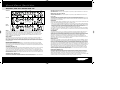
#14251 - Bass Op amends
9/4/03
11:25 am
Page 1
Park Farm • Inworth • Colchester • Essex • CO5 9SH
http://www.ashdownmusic.com
O perating
I nstructio ns
ABM/RPM-1 Amplifier Heads and ABM Combos
MAG 250 Amplifier Head and Combos
Electric Blue 150 Combos
#14251 - Bass Op amends
9/4/03
11:25 am
Page 3
Important Safety Instructions
BASIC PRECAUTIONS
Thank you for purchasing your Ashdown Engineering Amplifier. If you live in the UK, please register
your purchase by completing this form and return it to the following address:
Ashdown Engineering Ltd., Park Farm, Inworth, Colchester, Essex CO5 9SH
(Alternatively you can register online at http://www.ashdownmusic.com)
If you live outside the UK, the local Ashdown distributor may have included a specific registration
form for your country.
Your Ashdown Engineering product details:
Model . . . . . . . . . . . . . . . . . . . . . . . . .
Voltage . . . . . . . . . . . . . . . . . . . . . . . .
Serial number . . . . . . . . . . . . . . . . . . . .
Colour . . . . . . . . . . . . . . . . . . . . . . . .
Tested by . . . . . . . . . . . . . . . . . . . . . .
Date . . . . . . . . . . . . . . . . . . . . . . . . .
5 Year Limited Lifetime Warranty
Your Ashdown Engineering amplifier has been manufactured to the highest standards, using the bestselected materials.To ensure its optimum performance, please ensure your amplifier is regularly serviced.
This product carries a LIMITED LIFETIME WARRANTY, against defects in materials and workmanship, for
the original purchaser. Ashdown Engineering will, at their discretion, replace or repair any product or part
thereof, which is found by Ashdown Engineering to be defective.This warranty shall not apply to the
damage of covering, fittings or finishes when affected by carelessness, accident or extreme climate changes.
Nor does it apply to normal wear and tear of parts such as valves, fuses, light bulbs, speakers, controls etc.
Please complete the lower section of this warranty and return it within 10 days of purchase to Ashdown
Engineering Ltd. at the above address. In the unlikely event of any defect, please contact an authorised
Ashdown Engineering dealer. All transport charges are to be pre-paid by the Owner. Unless the
registration card is returned normal country warranty laws apply.
Important - Registration Card
Please complete and return this warranty within 10 days of purchase. Include any comments if possible.
Name .
Address
......
......
......
......
Age . . .
.
.
.
.
.
.
.
.
.
.
.
.
.
.
.
.
.
.
.
.
.
.
.
.
.
.
.
.
.
.
.
.
.
.
.
.
.
.
.
.
.
.
.
.
.
.
.
.
.
.
.
.
.
.
.
.
.
.
.
.
.
.
.
.
.
.
.
.
.
.
.
.
.
.
.
.
.
.
.
.
.
.
.
.
.
.
.
.
.
.
.
.
.
.
.
.
.
.
.
.
.
.
.
.
.
.
.
.
.
.
.
.
.
.
.
.
.
.
.
.
.
.
.
.
.
.
.
.
.
.
.
.
.
.
.
.
.
.
.
.
.
.
.
.
.
.
.
.
.
.
.
.
.
.
.
.
.
.
.
.
.
.
.
.
.
.
.
.
Comments
........
........
........
........
.
.
.
.
.
.
.
.
.
.
.
.
.
.
.
.
.
.
.
.
.
.
.
.
.
.
.
.
.
.
.
.
.
.
.
.
.
.
.
.
.
.
.
.
.
.
.
.
.
.
.
.
.
.
.
.
.
.
.
.
.
.
.
.
.
.
.
.
.
.
.
.
.
.
.
.
.
.
.
.
.
.
.
.
.
.
.
.
.
.
.
.
.
.
.
.
.
.
.
.
.
.
.
.
.
.
.
.
.
.
.
.
.
.
.
.
.
.
.
.
.
.
.
.
.
.
.
.
.
.
.
.
.
.
.
.
.
.
.
.
.
.
.
.
.
Purchased from
Date . . . . . . .
Model . . . . . .
Serial Number
.
.
.
.
.
.
.
.
.
.
.
.
.
.
.
.
.
.
.
.
.
.
.
.
.
.
.
.
.
.
.
.
.
.
.
.
.
.
.
.
.
.
.
.
.
.
.
.
.
.
.
.
.
.
.
.
.
.
.
.
.
.
.
.
.
.
.
.
.
.
.
.
.
.
.
.
.
.
.
.
.
.
.
.
.
.
.
.
.
.
.
.
.
.
.
.
.
.
.
.
.
.
.
.
.
.
.
.
.
.
.
.
.
.
.
.
.
.
.
.
.
.
.
.
.
.
.
.
.
.
.
.
.
.
.
.
.
.
.
.
.
.
.
.
.
.
.
.
.
.
.
.
.
.
.
.
.
.
.
.
.
.
.
.
.
.
.
.
.
.
.
.
.
.
.
.
.
.
.
.
.
.
.
.
.
.
.
.
.
.
.
.
.
.
.
.
.
.
.
.
.
.
.
.
.
.
.
.
.
.
.
.
.
.
.
.
.
WARNING - When using electrical products, basic precautions should be followed, including the following:
1.
2.
Read all the instructions before using the product.
Do not use this product near water – for example, near a bathtub, washbowl, kitchen sink, in a wet
basement or near a swimming pool.
3. This product may cause permanent hearing loss. Do not operate for long periods of time at a high
volume level or at any level that is uncomfortable. If you experience any hearing loss or ringing in the
ears, you should consult an audiologist.
4. Make sure nothing interferes with the ventilation of the product when in use.
5. The product should be located away from heat sources such as radiators, heat registers, or other
products that produce heat.
6. The product should be connected to a power supply of the type described in the operating
instructions or as marked on the product.
7. The power supply cord of the product should be unplugged from the outlet when left unused for a
long period of time.
8. Care should be taken so that objects do not fall and liquids are not spilled into the enclosure through
openings.
9. The product should be serviced by qualified personnel when:
a. The power supply cord or the plug has been damaged; or
b. Objects have fallen, or liquid has been spilled into the product: or
c. The product has been exposed to rain or moisture: or
d. The product does not appear to operate normally or exhibits a marked change in performance: or
e. The product has been dropped, or the enclosure damaged.
10. Do not attempt to service the product. All servicing should be referred to qualified service personnel.
11. For continued protection against the risk of fire, replace fuses only with those of the same type and
rating as indicated on the back of the product.
WARNINGS USED ON THE EQUIPMENT
#14251 - Bass Op amends
9/4/03
11:25 am
Page 5
The ABM Design Philosophy
This is a NO COMPROMISE design using the best parts available wherever possible.
The lightning flash with the arrow head symbol within an equilateral triangle is intended to
alert the user to the presence of uninsulated ‘dangerous voltage’ within this product’s
enclosure that may be of sufficient magnitude to constitute a risk of electric shock.
The exclamation point within an equilateral triangle is intended to alert the user to the
presence of important operating and maintenance (servicing) instructions in the literature
accompanying this product.
Some examples of this are as follows:
•
•
•
•
•
GROUNDING INSTRUCTIONS
•
This product must be grounded (earthed). If it should malfunction or breakdown, grounding
provides a path of least resistance for electric current to reduce the risk of electric shock. This
product is equipped with a supply cord having an equipment grounding conductor and a
grounding plug. The plug must be plugged into an appropriate outlet that is properly installed
and grounded in accordance with the local codes and ordinances.
DANGER - Improper connection of the equipment grounding conductor can result in a risk of
electric shock. Check with a qualified electrician or serviceman if you are in doubt as to
whether the product is properly grounded. Do not modify the plug provided with the product
– if it will not fit the outlet, have a proper outlet fitted.
The wires in this mains cord are coloured in accordance with the following code:
Green & Yellow - Earth
Blue - Neutral
Brown - Live
CE MARK FOR EUROPEAN HARMONISED STANDARDS
The CE mark which is attached to these products means it conforms to EMC Directive
(89/69/EEC), CE mark Directive (93/68/EEC) and Low Voltage Directive (72/23/EEC).
•
•
•
•
•
•
Gold plated jack sockets for reliability and long life.
Full metal XLR sockets for strength and their positive latching facility.
Powerful output stages for extra headroom (rated in English RMS real power and not MUSIC or
PEAK power as these can claim to be 2 or 3 times the actual real power of the amplifier).
Doubling up of the cooling fans for reliability and reduced fan noise (2 fans can run at half the speed
to provide the same cooling capacity and as a consequence generate only half the noise of one fan
running at twice the speed).
Speed controlled fan drive circuit. Again this reduces the amount of fan noise as the fans run slow
when the unit is cool and increase in speed with output power demands.
Powerful TOROIDAL mains transformer. This is more expensive than a laminated stack transformer
but has better regulation, i.e., provides more power on demand without sagging out and also has a
minimal external magnetic field which means that single coil pick up basses are less likely to pick up
mains hum from the amplifier.
FET input circuit to the preamp for ‘Warmth’ even when using the CLEAN input mix setting.
D.C. heaters for the TUBE section for low noise operation.
Switch on delay for silent power up.
Thermal trip for output protection.
Relay switched speaker output lines for silent power down.
Sub Bass output and Sub Harmonics facility for really serious bottom end.
Everything possible has been done to make this a reliable, top of the range, minimum service, high quality,
long lasting powerful bass amplifier.
We know you will appreciate the effort that has been put into the design and manufacture of this unit
and you will be rewarded in your choice of bass amplifier by long life and reliability.
#14251 - Bass Op amends
9/4/03
11:25 am
Page 7
Fro nt Panel Facilities
ABM, RPM-1, MAG 250 & ELECTRIC BLUE 150
ABM/RPM-1
DEEP (Electric Blue 150 & MAG 250)
With this button IN, a fixed E.Q. is superimposed on the preamp to give a BASS boost to the sound.This
gives +8dB at 50Hz.
BRIGHT (Electric Blue 150 & MAG 250)
With this button IN, a fixed E.Q. is superimposed on the preamp to give a TREBLE boost to the sound.
This gives +10dB at 10kHz.
MAG 250
Electric
Blue 150
INPUTS
On the MAG 250 and Electric Blue 150, there are two choices of instrument input, these are marked
HIGH and LOW.The HIGH input is high sensitivity and also high impedance to suit the output from
PASSIVE basses.The LOW input is low sensitivity and lower impedance to suit the output from ACTIVE
basses.The ABM has a single instrument input provided, linked to a PASSIVE/ACTIVE selector switch
(switch out=PASSIVE, switch in=ACTIVE).
INPUT CONTROL
The INPUT control sets the signal level through the preamp in conjunction with the INPUT LEVEL VU
Meter (Electric Blue 150 uses a LED display).This is adjusted to give a reading of 0VU on the meter
(yellow LED on Electric Blue 150) for average playing dynamics with occasional peaks into the red (red
LED on Electric Blue 150) region. Please note that this setting may require re-adjustment after modification
of the EQ controls.
PUSH FLAT / SHAPE (ABM/RPM-1 only)
With this button in its OUT position a fixed E.Q. is superimposed on the preamp to give a bright but
punchy character to the sound. Pushing this button IN returns the preamp to a Flat frequency response.
This function may also be controlled from a footswitch. For the footswitch to operate, this button must be
in its OUT position.
VALVE DRIVE (ABM/RPM-1 only)
This routes the signal either through a clean Solid State amplification section (control on zero) or through
a Dual Triode Tube amplification/overdrive section to add either tonal character, i.e. warmth with the
control set at 9 o’clock, a slight edge in the sound at 12 o’clock, through to an increasing degree of Tube
distortion/overdrive as the control is advanced to maximum. A Mix of these two amplification sections can
be achieved with this control. N.B.The degree of Tube distortion with this control will also depend on the
setting of the INPUT control.
VALVE DRIVE IN/OUT (ABM/RPM-1 only)
This push button switches the valve drive section IN or OUT.This function may also be controlled from a
footswitch. For the footswitch to operate this button must be in its OUT position.
E.Q. IN / OUT
This button switches the Equalisation section IN or OUT, i.e., the Bass, Middle and Treble controls and the
two sets of sliders (rotary controls on Electric Blue 150) placed between these.This facility is
footswitchable on the ABM/RPM-1 range via a socket on the rear panel. For the footswitch to operate this
button must be in its out position.
EQUALISATION
This consists of BASS, MIDDLE and TREBLE controls with two sliders (rotary controls on Electric Blue 150
& MAG 250) placed in between.This can be used in a number of ways:
• Firstly as a very simple Bass, Middle and Treble tone control section as found on older traditional amplifiers.
This is done by leaving the two sets of sliders (rotary controls on Electric Blue 150 & MAG 250) set in their
centre positions and using only the BASS, MIDDLE and TREBLE controls to alter the overall tone.
• Secondly, if more control is required, then the sliders (rotary controls on Electric Blue 150 & MAG 250)
can also be used to tailor the E.Q. in the regions between the main tone controls.
This provides a very versatile Equalisation section that is simple to understand and operate, yet provides a
wide degree of variation. It retains the simplicity of a three-control tone section but provides the flexibility
of a graphic equaliser.
SUB HARMONICS
This section consists of an IN / OUT switch and a LEVEL control.When switched IN, Sub Harmonics an
octave below the notes being played are produced.The level of these Sub Harmonics relative to the
straight bass sound can be adjusted using the LEVEL control.This is very effective in thickening the sound
and you will find in use that only a small degree of this lower octave is required to really fill out the sound
and provide a character to the sound that is not possible by any other means.The degree of Sub
Harmonics is also dependant on the setting of the BASS control.This facility is footswitchable on the
ABM/RPM-1 range via a socket on the rear panel. For the footswitch to operate the Sub Harmonics must
first be switched into circuit with the front panel push button.
DIRECT INJECT (D.I.)
A balanced D.I. is provided on the front panel rugged metal latching XLR socket.The ABM/RPM-1 features
a push button placed below the XLR that allows the user to choose either a Pre E.Q. / Pre Sub signal or a
Post E.Q. / Post Sub and Effects signal (the Pre E.Q. signal also includes the Shape facility, if this is switched
into circuit) – EBs and MAGs feature a Post E.Q. / Post Sub and Effects signal.The output signal from this
XLR socket is set to a level and impedance suitable for connecting directly into the Microphone input of a
mixing desk for either Direct Injection into the PA system or for recording.This must ONLY be used into a
Balanced Microphone input. It is not intended for any other type of connection.This has a floating ground
that is referenced to the mixing console it is plugged into and should not need ground lifting. It is also
unaffected by Phantom Powering on the Microphone input. Make sure your XLR plug does not have the
shell of the plug internally connected to the ground signal or this will connect the system to the chassis
ground of the amplifier and may cause problems with hum.
PUSH TO MUTE (ABM/RPM-1 only)
When pushed IN this button mutes the output from the preamp to the power amp, mutes the output
from the D.I. socket and mutes the output from the Sub Out socket as well.This leaves the output from
the TUNER / LINE socket still available to allow muted tuning. An LED is provided next to this switch to
indicate when the amplifier is muted.This operates only from the front panel MUTE push switch, i.e.
pressing this button mutes all sound from the amplifier and allows a tuner connected to the TUNER / LINE
socket to operate for silent tuning. Release the button and you are back in action again.
#14251 - Bass Op amends
9/4/03
11:25 am
Page 9
Fro nt/ Rear Panel Facilities
ABM, RPM-1, MAG 250 & ELECTRIC BLUE 150
TUNER / LINE OUT
This output socket provides a line level signal that can be used either for a permanent connection to a
tuner or a line output to slave up to other power amplifiers. (ABM/RPM-1 users - Please note that if this
socket is used as a slave output to other power amplifiers that the MUTE button will not mute the signal
to the external power amplifiers.)
SUB OUT (ABM/RPM-1 only)
This output socket provides a Low Pass filtered output for connection to a power amplifier driving a sub
unit for additional extra-low bottom end.This may also be used to drive other power amplifiers to provide
additional low bottom end to the system.The Low Pass filter is fixed at 160Hz.
OUTPUT LEVEL
The OUTPUT control adjusts the overall level of the amplifier. Adjust this for your preferred overall stage
playing volume.
300 / 500 WATT ABM HEAD / COMBO
REAR PANEL FACILITIES
LINE INPUT (ABM/RPM-1 only)
The rear panel has a Line Input socket for connection of other signal sources into the system.This can be
used for plugging a CD,Tape or MiniDisc player into the amplifier for practising or rehearsing or for
connection of a second preamp into the system.
47
42
3
2
1
12
0
10
0
RPM1 RACK-MOUNT PREAMP
65
95
SPEAKER OUTPUT (except Rack Preamp RPM1)
The Speaker Output sockets are also situated on the rear panel of the unit.The ABM provides both jack
and speakon connectors.
52
9
CROSSOVER AND OUTPUTS (Rack Preamp RPM1 only)
The BASS MAGNIFIER RACK PREAMP RPM1 has a built in high precision CROSSOVER with separate jack
socket outputs for the HIGH PASS and LOW PASS signals. Crossover frequency is adjustable from 35Hz to
160Hz with a level control for the LOW PASS output to adjust the balance between LOW and HIGH
outputs signals.There is also a FULL RANGE jack line output provided.This section is provided with
switched output levels for simplified connection to power amplifiers that require either a 0dB or +4dB
signal level.This switches the levels of all three outputs.
58
6
39
5
75
o
8
I
35
4
7
FOOTSWITCH SOCKETS (ABM/RPM-1)
Two stereo jack sockets marked SUB/VALVE and EQ/SHAPE are provided for connection of 2-way push
on/push off type foot switches.The SUB footswitch mutes the Sub Harmonics when closed. For this to
operate the Sub Harmonics must already be activated with the front panel push switch. For all other
footswitches to operate, the corresponding front panel push buttons must be in their OUT position.
900 WATT ABM HEAD / COMBO
0
15
EFFECTS SEND / RETURN (rear panel on ABM/RPM-1 & front panel on MAG 250 & Electric Blue 150)
A serial effects loop is provided at a level of 0dB.The Effects Send and Return sockets for this are on the
rear panel of the ABM/RPM-1 and front panel of the MAG 250 and Electric Blue 150 below the D.I. socket.
The EFFECTS SEND socket can also be used as a Line Out socket if required.The signal path through the
preamp is only broken when a jack plug is inserted into the EFFECTS RETURN socket.The EFFECTS
SEND is situated after the EQ,Valve section and Sub Bass Processor.
#14251 - Bass Op amends
9/4/03
11:25 am
Page 11
Specificatio ns
ABM, MAG 250 & ELECTRIC BLUE 150 PREAMPS
INPUTS
High Input
Low Input
Line Input (ABM only)
Effects Return
Impedance
Impedance
Impedance
Impedance
3.9M Ohms
10K Ohms
22K Ohms
22K Ohms
Input
Input
Input
Input
range 150mV to 20V p-p
range 300mV to 40V p-p
level 0dBu nominal
level 0dBu nominal
Level
Level
Level
Level
Level
Level
Level
0dBu nominal
0dBu nominal
0dBu nominal
-20dBu nominal
switched 0/+4dBU
switched 0/+4dBU
switched 0/+4dBU
OUTPUTS
Tuner Output
Sub Output (ABM only)
Effects Send
D.I. Output
Low Pass (RPM1 only)
High Pass (RPM1 only)
Full Range (RPM1 only)
Speaker Outputs
Impedance 22K Ohms
Impedance 22K Ohms
Impedance 22K Ohms
600 Ohms balanced
Impedance 1K Ohms
Impedance 1K Ohms
Impedance 1K Ohms
Minimum impedance 4 Ohms
EQUALISATION (Electric Blue 150 & MAG 250)
EQUALISATION (ABM)
Bass
Lo Mid
Middle
Hi Mid
Treble
Deep
Bright
Signal to Noise
Distortion
Shape (Push Flat)
+/-15dB @ 100Hz
+/-15dB @ 220Hz
+/-15dB @ 660Hz
+/-15dB @ 1.6kHz
+/-15dB @ 7kHz shelving
+8dB @ 50Hz
+10dB @ 10kHz
Better than 80dB (EQ flat)
Less than 0.5% THD
Bass
Middle
Treble
Slider1
Slider 2
Slider 3
Slider 4
+8dB @ 50Hz & 4kHz, -8dB @
400Hz, filter slope - 6dB/octave
+/-15dB @ 45Hz
+/-15dB @ 660Hz
+/-15dB @ 7kHz shelving
+/-15dB @ 110Hz
+/-15dB @ 340Hz
+/-15dB @ 1.3kHz
+/-15dB @ 2.6kHz
GENERAL SPECIFICATION
Frequency Response
Rack Preamp RPM1 Crossover
Power Requirements
-3dB at 17Hz and 30KHz (Electric Blue 150: -3dB at 22Hz and 25KHz)
Variable between 35 and 160Hz
230 / 115V
Park Farm • Inworth • Colchester • Essex • CO5 9SH
E-mail: [email protected]