1
SERVICE MANUAL
SERVICE SPECIFICATIONS
4547
RD RELAYS
The Style RD designation includes a group of direct current, two position,
polar-type relays. The fundamental design, physical dimensions, and general
appearances of this entire group are identical, but various coil resistances and
calibration values are furnished to suit specific applications. This service specification gives calibration tables and service instructions for Style RD relays.
Because of the special fixtures required in the assembly of these relays, it is
recommended that they be returned to the factory when major repairs involving
replacement of parts are required. However, where facilities are available to
handle major repairs, reference should be made to Service Specification SU4547-A.
I.
COMMON FEATURES
RD relays are individually housed with all operating parts fully enclosed and
sealed. All contacts are visible through the front cover.
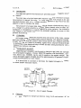
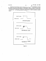
RD relays have two separate coil circuits which may be used independently,
or in combination, to suit requirements as shown in Figure 1.
SERIES
Mt>l.TIPLE
ll'H)lPENOENT
TERMINAL MARKINGS AS FOUND ON RELAY MOUNTING BASE
Figufel - RD Relay Coil Connections
RD relays are plug connected for quick and easy replacement. Coded key
slots are provided in the relay case to mesh with pins in the mounting base,
thereby preventing insertiQn of a given relay into an incorrect mounting base.
The pin plate on each mow~ bas~ contains five pins in various combinations.
Each separate type of RD reliay has an individual combination assignment. Slots
are milled in the base of each relay to mate!\; this assignment. The numbers
which remain on the base of the relay after tlie slots have been cut identify the
code combination for that re lay.
March 1959
Rev. 7/83
PRINTED IN USA
UNION SWITCH &·SIGNAL DIVISION
AMERICAN STANDARD INC. I SWISSVALE, ~Ii 15218
U.S. & S.
II.
Service Spec. SU-4547
- 2 -
OPERATION
Two different types of relay operation are provided; namely, "magnetic stick"
or ''biased''.
The stick type relay (red name plate) requires a polarity reversal to actuate
the armature to operate the relay. The relay armature will remain in its last
operated position until a d:-c. voltage of polarity opposite to that which was last
applied is used to energize the relay.
The armature of a biased type relay picks-up (moves clockwise) only when a
d-c. voltage of a given polarity is applied. When a biased relay is either deenergized or energized by a voltage opposite the given polarity, the armature
will remain in the counter-clockwise (de-energized) position or return to this
position if picked up.
fil.
CLEANING
All foreign matter should be removed from the interior of the relay, paying
particular attention to the contacts and armature stop pins. For general cleaning,
a small, dry, fine-bristled (camel's hair) brush may be used. Contacts and stop
pin surfaces may be cleaned by brushing lightly with a clean fine-bristled brush
moistened with clean denatured ethyl alcohol and then drying immediately with a
strip of clean lintless cloth tape.
IV.
PERMANENT MAGNET
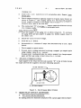
Magnet Charger U0340001 may be used to charge or age (reduce the strength
of) the permanent magnets. Fixture UN327763 together with Gauss Meter, General Electric Cat. #416X29, can be used to measure the magnet strength. The
initial permanent magnet strength should be approximately 90 gausses for biased
relays and 80 gausses for stick relays.
It is permissible to increase or decrease the magnet strength if necessary
to obtain proper calibration values.
ADAPTER (2)
PERMANENT
MAGNET
LIM320079
CORE
CHARGING.
COIL
(LARGE)
AGING COIL
(SMALL)
VARIAC TRANSFORMER
OR POTENTIOMETER
/
....____._._ _--+-...J
--=-~-------'
L--.t---..--0IIOV.
A.C.
5 AMPS.A.C.
Figure 2 - Use of Magnet Charger
A.
Charging
1.
Place magnet on charger as shown in Figure 2 with end marked ''N" on
\
U.S. & S.
Service Spec. SU-4547
- 3 -
charging coil.
B.
2.
Close 110 V. D. C. switch for 2 or 3 seconds, then open. Repeat, leave
switch open.
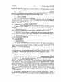
3.
Check magnet strength by applying magnet to the gauss meter fixture as
shown in Figure 3. The reading should be no less than 100 gausses.
Actual magnet strength is much higher since the fixture is arranged to
measure only a part of the total flux.
4.
The end marked ''N'' of a properly charged magnet should attract the end
of a compass needle which points to geographic South.
Aging (Reducing Strength)
1.
Place the magnet on the aging coil as shown in Figure 2. To increase
the aging effect per unit ampere in aging coil, hold the magnet closer to
the center core.
2.
Adjust the variac for zero voltage.
3.
Close the A. C. Switch.
4.
Increase the a-c. current to 5 amps. then decrease slowly to zero. Open
Switch.
5.
Check magnet on gauss meter.
6.
If gauss meter reading indicates too strong a magnet, age magnet again
using a higher value of a-c. current.
If gauss meter reading indicates too weak a magnet, fully charge magnet
again and then age using a lower value of a-c. current.
C.
Application of Magnets to Relay
Apply magnet to the relay with the side marked "N" to the left (when facing
the magnet and with the magnetic structure extending upward}.
FIXTURE UN327763
AIR GAP 0.048
Figure 3 - Use of Gauss Meter Fixture
V.
BIASED RELAY CONTACT ADJUSTMENT
A.
Heel Contact Spring Adjustment
,\
All spring pressures should be measured with a gram gage (Imtra Corpor-
U.S. & S.
\
Service Spec. SU-4547
- 4 -
ation), UJ620304, 10-80 grams, or equivalent. The gage should be applied to
the contact spring next to the contact button on the side toward the weld. With
gage at right angles to the contact spring, the force necessary to lift the spring
away from the nylon rotor should be measured. This force should not be less
than 20 grams nor more than 24 grams.
To check the pressure oftheflexibleY heel springs, insertgages, UM372029,
at each end of the armature with the side of the gage marked "bias" on the same
side as the higher stop pin. These gages hold the armature in mid-position
while the pressures of the Y springs are checked. All contacts should be open
during this check. If necessary, the semi-rigid contact fingers should be bent
to just open the contacts.
If a Y spring is found to have too little pressure, the pressure can be increased by opening the vertex of the Y spring with a metal rod (1/16" diameter).
Pressures can be reduced by closing the vertex with a pair of tweezers. Care
should be exercised to avoid permanently distorting the Y springs. If there is
a marked unbalance between the pressures on the two sides of an individual spring,
bend the Y spring at a point adjacent to the supporting stem in a direction which
will equalize the pressures.
The single flexible springs are checked with the gages removed and the armature in the released or counter-clockwise position, (viewed from the front of the
relay). Pressures on the single flexible heel spring can be adjusted by bending
them slightly at the support. All bending should be done with a contact spring
bender.
B.
Back Contact Adjustment
Back contacts (those which are made when the armature is in the counterclockwise position) should be adjusted using gages, UM372032. With the relay
face down and turned so that the permanent magnet side of the relay is the near
side, place the gages between the armature and the pole faces. Insert the gages
on either end of the armature so the side marked "Bias-B" of the right gage is
on the far side and the side marked "Bias-B" of the left gage is on the near side.
Plug the relay into fixture UN322799 which is essentially an RD relay mounting base equipped with contact indicating lamps. Using a spring bender, UR375786,
applied near the welded end of the semi-rigid back contact member, bend the
member so that both of its contact buttons just make with both of the corresponding
Y heel spring contact buttons. If both of the contacts do not make simultaneously,
use the narrow slotted end of tool, UM375775, to bend the post to which the contacts are welded just enough to align the contacts vertically. If necessary to
raise or lower the Y spring contacts use the wide slotted end of the tool to bend
the post. A lamp will indicate when the Y heel spring is made with either a front
or back contact. The contact is properly adjusted when a light touch on the
semi-rigid member extinguishes the lamp.
C.
Front Contact Adjustment
After the four back contacts have been adjusted, remove the relay from
the fixture and remove the gages from the relay. Now insert gages, UM372031,
with the side marked "Bias-F" opposite to the position given above for the side
marked "Bias-B" of the back contact gages. Plug the relay into the fixture and
\
u. s. & s.
- 5 -
Service Spec. SU-4547
adjust the eight semi-rigid front contact members in the same manner as described for the back contacts.
Care must be exercised when bending the semi-rigid front contact members
adjacent to the bakelite cross members which support the front pivot. Pressure
exerted by the bending tool against the bakelite might cause breakage.
D.
Contact Openings
After the contacts have been adjusted, remove the relay from the test fixture and insert the same gages, UM372029, that were used for adjusting the
flexible Y heel springs (Section V-A). All contacts should be open by approximately 0. 002 inch.
VI.
STICK RELAY CONTACT ADJUSTMENT
A. Heel Contact Springs should be adjusted the same as outlined in Section
V-A except that gages, UM372028, should be used to position the armature.
B. Reverse Contacts should be adjusted the same as outlined in Section V-B
(back contacts of biased relay) using gages, UM372030 (marked "Stick").
C. Normal Contacts should be adjusted the same as outlined in Section V -C
(front contacts of biased relay) except using gages, UM372030 (marked "Stick").
D. Contact Openings should be checked the same as outlined in Section V-D
except using gages, UM372028.
VII.
CALIBRATION
A.
Biased Relays
Test fixture UN334998 which is wired to connect the relay coils in series is
used to check relay calibration values. Voltage d-c. is applied to the test fixture
from a potentiometer and the current is measured with a milliammeter in the
positive (+) coil lead to the fixture.
Set the potentiometer for a low output voltage. Throw the two top switches
on the fixture up, and the bottom switch to the right. Positive polarity should
now appear on the top right hand receptacle of the fixture and negative polarity
should appear on the lower left hand receptacle.
Plug the biased relay into the fixture.
Increase the voltage until the current reaches the value given under "Charge"
in Table #1. The relay armature should now be in the clockwise or picked up
position. Decrease the voltage until the relay armature drops away to the counterclockwise position. The current at which the armature moves from the clockwise position to the counterclockwise position is the drop-away value. Momentarily open the circuit by throwing the bottom switch to the left and returning it to
the right. Gradually increase the voltage until the relay armature moves once
again to the clockwise position. The current at which the armature moves from
the counterclockwise position to the clockwise position is the pick-up value.
These current values must agree with the values given in Table #1 for proper
relay calibration.
If the relay calibration does not conform with the values given in Table #1
check the contact adjustments once again befo~e making the adjustments described below:
U.S. & S.
\
- 6-
Service Spec. SU-4547
If the relay does not meet with the required calibration values or if the armature hangs in the mid position, adjustments must be made to the biasing springs
and/or the permanent magnet. A relay armature is "hanging" when it fails to
move without hesitation from one pole face to the opposite pole face at the required pick-up or drop-away current value given for calibration.
Hanging on drop-away may be caused by a weak permanent magnet, insufficient pressure in the biasing springs, or a combination of the two. Hanging on
pick-up is caused by excessive pressure on the biasing springs. When adjusting
the biasing springs an effort should be made to maintain nearly equal pressure
in each of the two springs.
In some cases the spring pressure in the Y heel springs and in the single
heel springs must be reduced in order to overcome hanging or to obtain proper
calibration. The pressure in these springs shouldnever be reduced below the 20
grams minimum value when measured as described in Section V. The pressure
in the Y heel springs and in the single heel springs should be changed to obtain
proper calibration only if it is found that allowable adjustment of the biasing
springs and of the magnet strength, as described in the following, is inadequate
to obtain proper calibration.
An increase of magnet strength raises the pickup value and decreases the
drop-away current value. A decrease in magnet strength has the opposite effect
on relay operation. An increase in the biasing spring pressure raises both the
pick-up and the drop-away current values. A decrease in biasing spring pressure has the opposite effect on relay operation.
B.
Magnetic Stick Relays
The same test fixture, UN334998, is used for calibrating both biased and
magnetic stick type relays. Set the potentiometer for low output voltage and throw
the two top switches down and the bottom switch to the left. Positive polarity
should appear on the lower left hand receptacle of the fixture and negative polarity should appear on the upper right hand receptacle. Throw the bottom switch
to the right and the polarity should reverse. Leave the switches in this position.
Plug the stick relay into the test fixture.
Increase the current to the value given under "Charge" in Table #1 and then
gradually reduce the current to zero. Throw the bottom switch to the left and
gradually increase the current until the relay picks up in the counterclockwise
direction. The current at which the relay armature moves without hesitation
from the clockwise position to the counterclockwise position is the reverse pickup value.
Continue to increase the current until the value given under ''Charge" is
reached and then gradually reduce the current to zero. Throw the bottom switch
to the right and gradually increase the current until the relay picks up in the
clockwise direction. The current at which the relay armature moves without
hesitation from the counterclockwise position to the clockwise position is the
normal pick-up value.
If the stick relay calibration does not conform with the values given in Table
#1, check the contact adjustments in accordance with Section VI before making
the adjustments as follows:
U.S. & S.
Service Spec. SU-4547
- 7 -
Since there are no biasing springs on a stick type relay, the adjustment of
the strength of the permanent magnet is the chief means used to obtain proper
calibration. A reduction of permanent magnet strength decreases the required
pick-up current (normal and reverse) and an increase of magnet strength raises
the required pick-up current.
If the relay cannot be properly calibrated by permanent magnet adjustment
alone and the relay armature hangs, reduce the pressure in the Y heel springs
keeping within the specified limits set forth in Section VI.
VIII.
CONTACT RESISTANCE
After cleaning the contacts as outlined in Section ill, individual contact resistances should be no more than 0. 03 ohm with the armature in the picked up
or released position.
IX.
SERVICE CALIBRATIONS
It is recommended that RD relays be removed from service when the calibration values are beyond the limits suggested in the calibration tables under the
heading of Field Limits.
X.
CONTACT AND BIAS SPRING REPLACEMENT
In the event any contact member or bias spring becomes unserviceable it
should be removed. To remove the semi-rigid members a force perpendicular
and away from the face of the relay should be applied to the member. A nail
with half its head removed is a convenient tool to use for this purpose. To remove the flexible members roll them free of the insert. A new member can then
be fastened to the relay body inserts by soldering as follows:
1. File off all the remnants of the old member until a smooth clean surface
results on the insert to which the member was welded and apply a thin film of
non-corrosive soldering flux.
2. With the armature held in mid-position, clamp the new member in place
making sure that the contacts are aligned and that the contact end of the spring
has clearance with respect to the nylon rotor.
3. Using an electric soldering iron heat the insert and apply solder, depending upon capillary action to carry the solder between the insert and the
member. The solder should not build up excessively on the member beyond the
limits of the insert.
4. Clean the excess flux from the joint. If a knife is used be careful not to
score the flexible springs as this can eventually lead to breakage.
The references for the replacement members are as follows:
Flexible "Y" Spring
Flexible Single Spring
Bias Spring
Semi-Rigid Contact Member
XI.
UN307995
UN307873
UN317482
UN307993
CONTACT BOUNCE TEST
As a final check of the continuity characteristics of the relay contacts a
contact bounce test is recommended. This tes, is performed by operating the
\
U.S. & S.
Service Spec. SU-4547
- 8 -
\,
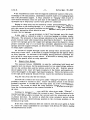
relay at approximately 25 cycles/sec. and then observing the trace of contact
make and break on an oscilloscope (Dumont Type 340 Pl screen or equivalent).
The relay can be operated either directly from a 25 cycle A. C. source or driven
at approximately 25 cycles by a 30 ohms-30 ohms RD stick type relay calibrated
to pick-up at 0. 053 ampere with the coils in series. The wiring and other details for the latter arrangement are found in Fig. 4.
MOUNTING BASE UN308766 FOR DRIVING RELAY, 30 OHMS - 30 OHMS RD STICK TYPE
CALIBRATED TO PICK-UP AT O 0~3 AMPERE WITH COILS IN SERIES.
t
MOUNTING BASE UN308766 WITH INDEXING PINS
REMOVED FOR RD RELAY UNDER TEST FOR CONTACT
BOUNCE . . . . . . . , . . - - - - - - - - - -
\IOLTAGE "A"
IIOLTAGE "B"
-----·t2
I
0
0
0
B
+I
8
0
F
0
0
0
B
BO
0
I
I
I
:: I
I
ti
8
F
0
0
------
0
0
F
2o
7
FO
0
0
30
0
0
BO
05
3
6
0
OB
FO
-2
I
OF
BO
~
4
i
5
--c
SWITCH "A"
EACH FRONT AND
BACK CONTACT TO
BE WIRED TO A
· POINT ON SWITCH "B"
\IOLTAGE"C"
------c,1
'°
TO
OSCILLOSCOPE
I
I
[
0
I
0
0
o
___.l•l•--1
45 \IOLT DRY CELL
0
- ----
VOLTAG£ "e"-ADJUSTABLE VOLTAGE,ADJUSTED TO
OPERATE RELAY UNDER TEST.
VOLTAGE "c" -MAINTAIN AT APPROXIMATELY 6.4 V.D.C.
I
I
I
I
~---o- -- __oj
0
VOLTAGE "A" -D.C. SUPPLY VOLTAGE, IOI/ FOR ALL RELAYS
EXCEPT l-"308002 WHICH REQUIRES 5011.
I
0
o
SWITCH
"A" -OPEN FOR BIAS RELAYS-CLOSED FOR STICK RELAYS.
SWITCH
"B" -SELECTOR SWITCH SELECTS CONTACT TO BE TESTED.
Figure 4
$WITCH 11 B"
O
O
0
O
O
U.S. & S.
(
Service Spec. SU-4547
- 9 -
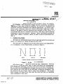
In this test some bounce will be observed in all contacts; the degree at which
this bounce becomes objectionable is illustrated in Fig. 5. Contacts which show
excessive bounce should be cleaned and checked for spring pressure per Sections
V-A and VI-A. Low spring pressure is the primary cause of excessive contact
bounce.
CONTACT CLOSED
l
CONTACT OPEN
SATISFACTORY CONTACT
CONTACT CLOSED
l'----
CONTACT OPEN
UNSATISFACTORY CONTACT
CONTACT CLOSED
1111
I
CONTACT OPEN
l_
UNSATISFACTORY CONTACT
Figure 5
s
Ul
ta'>
?l
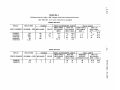
TABLE NO. 1
Calibration Data For Style "RD" Relays With Coils Connected In Series
(See Table No. 2 for coils connected in multiple)
BIASED RELAYS
RELAY
RELAY RES.
PIECE NUMBER
(IN OHMS ± 10%)
MILLIAMPS.
VOLTS
100
3460
200
60
120
32
84
140
12
110
17
9
UN386450
r~
2.50
CHARGE
SHOP ADJUSTMENTS LIMITS
FIELD LIMITS
DROP-AWAY
PICK-UP
DROP-AWAY
PICK-UP
MILLIAMPS.
MILLIAMPS.
MILLIAMPS.
MILLIAMPS.
(MIN.)
(MIN.) (MAX. )
(MIN.)
(MIN. ) (MAX.)
I
l
I
I
49.0
~
10.0
1. 3
2.0
5.0
51
7.8
34
57
65.0
10. 2
46.0
77.0
425
......
0
STICK RELAYS
RELAY
RELAY RES.
PIECE NUMBER
(IN OHMS± 10%)
UN308000
UN308003
60
572
CHARGE
MILLIAMPS.
66
28
VOLTS
5
18
FIELD LIMITS
SHOP ADJUSTMENTS LIMITS
PICK-UP
DROP-AWAY
PICK-UP
MINIMUM
MILLIAMPS.
MIL LIAM PS.
MILLIAMPS.
SERVICE
(MIN. ) (MAX. ) ENERGIZATION (MIN. ) (MAX. )
(MIN.)
29
13
33
14
66
22
22.0
11. 5
36.0
15. 5
Ul
(I)
~
.....
(')
(1)
rn
"O
(I)
(')
Ul
c
I
""'
U1
""'
-.J
(j
(/)
~
~
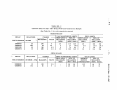
TABLE NO. 2
Calibration Data For Style "RD" Relays With Coils Connected in Multiple
(See Table No. 1 for coils connected in series)
BIASED RELAYS
RELAY
RELAY RES.
PIECE NUMBER
(IN OHMS ± 10%)
MIL LIAM PS.
UN308001
UN308002
UN315538
UN318614
25
865
50
15
240
64
168
280
CHARGE
VOLTS
6
55
8. 5
4. 5
SHOP ADJUSTMENTS LIMITS
FIELD LIMITS
PICK-UP
DROP-AWAY
DROP-AWAY
PICK-UP
MILLIAMPS.
MIL LIA MPS.
MILLIAMPS.
MILLIAMPS.
(MIN.)
(MIN. ) (MAX. )
(MIN.)
(MIN.) (MAX.)
30
3
6
15
110
17
74
126
120
18.6
84
140
20
2.6
4
10
102
15.6
68
114
130
20.4
92
154
....
....
STICK RELAYS
,..s"
.-
RELAY
RELAY RES.
PIECE NUMBER
(IN OHMS± 10%)
MILLIAMPS.
UN308000
UN308003
15
143
132
56
CHARGE
VOLTS
2. 5
9
FIELD LIMITS
SHOP ADJUSTMENTS LIMITS
DROP-AWAY
PICK-UP
PICK-UP
MINIMUM
MILLIAMPS.
SERVICE
MIL LIAM PS.
MILLIAMPS.
(MIN.)
(MIN. ) (MAX. ) ENERGIZATION (MIN. ) (MAX. )
-
-
58
26
66
28
132
44
44
23
72
31
(/)
(I)
""l
<
....
r:,
(I)
.g,
.
(I)
r:,
Ul
(j
I
""'
""'
t11
-;J