1
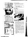
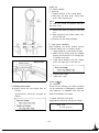
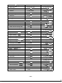
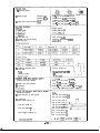
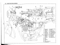
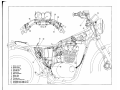
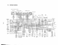
Supplementary
FOR XS650SE MODELS AFTER ENGINE SERIAL NUMBER 2FO-114241
FOREWORD
This Supplementary Service Manual for XS650SE has been published to
supplement the Service Manual for the XS650E (LIT-11616-00-76), and
provides updated information for the XS650E model as well as new data
concerning the XS650SE. For complete information on service procedures,
it is necessary to use this Supplementary Service Manual together with the
Service Manual for the XS650E (LIT-1 1616-00-76).
NOTE:
This Supplementary Manual contains special information regarding periodic
maintenance to the emissions control system for the XS650SE. Please read
this material carefully.
SERVICE DEPT.
INTERNATIONAL DlVlSION
YAMAHA MOTOR CO., LTD.
Page numbers shown in brackets correspond
to page numbers of the XS650E Service
Manual (LIT-1 1616-00-76).
(PAGE 4 - 5)
2-2. MAINTENANCE INTERVALS CHARTS
A. PERIODIC MAINTENANCE EMISSION CONTROL SYSTEM
REMARKS
)
Check for leakage. Retlghten as netsR e p l a c e gasket(s) of newssaw.
~
j
0
I
0
8
1
Exhaust System
9
!
I
Carburetor
Svnchronuatlon
Ad,us, synchron,zat,o” Of carburetors.1
0
0
0
Idle Speed
Check and adjust engnne Idle speed.
Adlust cable free play.
0
0
0
10
sary.
/
0
B. GENERAL MAINTENANCE/LUBRICATION
INITIAL
VO.
ITEM
REMARKS
TYPE
I
I
Warm-up engine before
drammg.
Adjust free play. Replace
pad If necessary.
B Rear Arm
Pwot Shaft
-t
0
I
0
_
0
Brake
System
Control a n d
Meter Cable
0
I
I
c
4
,
,
0
Dry type filter Clean
wth compressed air
Drwe Chaan
Yamalube 4.cycle
011 or SAE 2OW/40
“SE” motor oil
8,000 km
I---1 6 , 0km
00
or 12 months or 24 months
1 5 , 0 0 0 mll l10.000 ma)
0
/AI, F,lter
6
THEREAFTEREVERY
4.000 km
or6 months
12,500 ml)
Clean element in solvent.
3
Tp”tch
BREAK-IN
1,000 km 5.000 km
or 1 month or 7 months
(600 muI
13,000 mil
Adjust free play.
Apply chain lube
thoroughly.
Apply cable lube
thoroughly
Yamaha chain and
cable lube or
low/30 motor 011
Yamaha chsln and
cable lube or
lOWl30 motor oil
0
0
0
0
0
0
CHECK CHAIN TENSION AND LUBE EVERY 500 km (300 ml)
0
0
0
Apply untel new grease
shows
Apply Ilghtly.
0
Yamaha chain and
cable lube or
low/30 mcltor 011
-lll-
cj
i’
I
I
NO.
I
ITEM
I
/ IN. I T I .AL
TYPE
REMARKS
B
- REAK-IN 1
16,000 km
4,000 km
8,000 km
1,000 km 5,000 km
or 1 month or 7 months or 6 months or 12 months or24month
l5.000 mil
(10,OQO mi
(600 mi)
( 3 . 0 0 0 mil 12.500 ml)
Yamaha fork oil
1OWt or equivalent
, , ;ynt Fork Dram completely.
I
Refill to speciflcatmn.
0
Steering Ball Check bearmgs assembly
Medwm weight
,2 Eearmg and for looseness. Moderately wheel bearing
repack every 16,000 km
Races
grease.
110,000 rni).
Check bearmgs for smooth
Medium weight
,3 W h e e l
rotation. Moderaltelv
wheel bearmg
Bearings
repack every 16,000 km
grease.
~lO,C00 mil.
1 4 Battery
Check specific gravity.
Check breather pipe for
proper operation.
,5 A . C .
Generator
Replace generator brushes.
Replace at initial 9.000
km 16.500 mi)
THEREAFTEREVERY
0
0
0
0
0
0
(PAGE 7 - 8)
2-3. ENGINE
B. Air filters
2. Cleaning method
c. The air filter element should be cleaned
every 8,000 km (5,000 mi). It should be
cleaned more often if the machine is
operated in extremely dusty areas.
Repack
0
-
In the XS650E Service Manual there are a few
pages that are not arranged in order. These
are pages 7, 8 and 9. They should be read in
the reverse order, i.e. 9,8 and 7.
Repack
(PAGE 9 - 13)
2-4. CHASSIS
A. Fuel petcock cleaning
1. Open the seat and remove the fuel tank
securing bolt.
2. Turn the petcock lever to the “ON” or
“RES” position. Raise the fuel tank to
remove the fuel pipe.
E. Cam chain adjustment
Check/adjust the cam chain tension as follows:
1. Remove the cap nut.
2. Turn the left end of the crankshaft
counterclockwise. As the crankshaft is
turning, check to see that the cam chain
adjuster push rod is flush with the end of
the bolt. If not, turn the adjuster bolt
until the push rod is flush.
3. Reinstall the cap nut. The cap nut acts
as a lock nut for the adjuster.
1. Fuel pipe
3. Remove the drain bolt and clean with
solvent. If gasket is damaged, replace.
1. Drain bolt
_/--1. cap nut
_/-------/
R
2. Adjuster bolt
j
3. Push rod
,:
E. Rear brake
The rear brake pedal should be so adjusted
that it has a free play of 13 - 15 mm (0.51
- 0.59 in) from when the brake pedal is first
moved to when the brake begins to be
effected.
1.
2.
I
Loosen the adjuster lock nut (for pedal
height).
Bridgestone or
Yokohama
130/90S164PR
Maximum load limit
166 kg (365 Ibl
279 kg (615 lb1
1.6 kg/cm2
(22 psi )
2.0 kg/cm*
(28 psi)
2.0 kglcmz
(28 psi 1
2.3 kg/cm2
(32 psi 1
2.0 kg/cm2
(28 psi I
2.3 kg/cm2
(32 psi I
1
90 kg (198 lb) load
- 204 kg (445 lb)
load (Maximum
load1
High speed riding
I
Minimum tire
tread depth
0.8 mm (0.03 in) 0.8 mm (0.03 in)
G. Drive chain
1. Tension check
- CAUTION:
See that the punched mark on the brake
rod is not above the top surface of the
adjuster lock nut in securing the brake rod
adjuster lock nut.
1.
2.
3.
4.
5.
Bridwstone or
Yokohama
3.50SlQ-lPR
Cold tire oressure:
Up to 90 kg
(198 lb) load
By turning the adjuster bolt clockwise or
counterclockwise, adjust the brake pedal
position so that its top end is approx. 12
- 18 mm (0.47 - 0.71 in) below the
footrest top end.
3. Secure the adjuster lock nut.
4. Loosen the brake rod adjuster lock nut
and screw brake rod downward until
there is noticeable free play between rod
and master cylinder.
5. Turn in the brake rod until it lightly
touches the master cylinder, then turn it
out by approx. 1-1/5 turns (for proper
free play).
6. Tighten the brake rod adjuster lock nut.
Standard tire
NOTE:
Before checking and/or adjusting, rotate
rear wheel through several revolutions and
check tension several times to find the
tightest point.
Check and/or adjust chain
tension with rear wheel in this “tight chain”
position.
Inspect the drive chain with both tires
touching the ground and without rider.
Check the tension at the position shown
in the illustration. The normal vertical
deflection is approximately 20 - 30 mm
(0.8 - 1.2 in). If the deflection exceeds
20 - 30 mm (0.8 - 1.2 in) adjust the
chain tension.
4
Adjuster bolt (for pedal height) 6. Pedal height 12 - 18 mm
(0.47 - 0 . 7 1 in)
Lock nut
7. Free play 13 - 15 mm
Lock nut
(0.51 -0.59 in)
Brake rod
Footrest
F. Wheels and tires
2. Tires
Specifications should be changed as
follows:
-113-
2. Tension adjustment
a. Remove the cotter pin of the rear wheel
axle nut with pliers.
b. Loosen the rear wheel axle nut.
C.
L o o s e n t h e IOU W. ,, ~“, ~~, To
tighten chain tur* ‘,W
_
2, 61 @lusters
clockwise. To Irfn *,W
,fl’ Mjustars
counterclockmw a/,
)* U,W! f o r ward. Turn ta7 vqnn
?/=?I / the
same amount ti FW+.
rv ‘l++f,t axle
alignment. (There VS. W5J”S ,,, 3ivh side
H. Front fork oil change
8. Pour specified amount of oil into the
inner tube through the upper end opening.
of rear arm and cf TV/ #,*, 9,,,rr. uoe
them to check for p--H -4;
(PAGE 14 - 15)
2-5. E L E C T R I C A L
C. Ignition timing
1. Point gap must be set before setting
timing.
2. Ignition timing is checked with a timing
light by observing the position of the
stationary marks stamped on the stator
6. bewp+ - - 2. Adjuster
3. Marks for alipnant
d. After adjusting, 8~ ,..,+ .,
c ‘j’t#ten the
3. Advanced mark
1. Too dead center
2.15” BTDC at 1,200 rlmn
CAUTION:-. .*,_
3.
NOTE:
-I_
Excessive chain tense ~1) ,,W,M the en_
gine and other vita, m
’ ‘W tlu: ternion
within the specifti iir& h, ,~~ the
rear axle cotter pin * * + k
-‘--
4.
5.
“_
6.
7.
-114-
.
Connect timing light to right (left)
cylinder spark plug lead wire. Ignition
timing of right cylinder must be set first.
Start the engine and keep the engine
speed as specified on the label. Use a
tachometer for checking.
The rotor pointer should line up the “F”
stamped timing mark on the stator at a
specified engine speed. If it does not
align, loosen the two breaker backing
plate screws (breaker assembly holding
screws for left cylinder) and move the
complete backing plate (breaker assembly for left cylinder) until the point
marks align.
Retighten screws. Check timing again
for right cylinder.
Repeat procedure (steps 2 - 6) for left
cylinder.
(PAGE 29 - 33)
3-4. ENGINE ASSEMBLY AND ADJUSTMENT
0. Engine
Specifications should be changed as
1. Right cylinder timing adjustment
2. Left cylinder timing adjurtment
F. Spark plug
Check electrode condition and wear, insulator
color and electrode gap. Use a wire gauge for
a adjusting the plug gap. If the electrodes
become too worn, replace it.
When installing the plug, always clean the
gasket surface, wipe off any grime that might
be present on the surface of the spark plug,
and torque the spark plug properly.
Standard spark plug:
N-7Y (CHAMPION) or BP7ES (NGK)
Spark plug gap:
0.7 - 0.8 mm (0.028 - 0.031 in)
Spark plug tightening torque:
2.0 m-kg (14.5 ft-lb)
Engine mounting bolt torCWe:
1.8 m-kg (13.0ft-lb)
Upper Kl Nut)
M8
3.0
m-kg (21.7 ft-lb)
M
l
0
Upper
4.6 m-kg (33.3 ft-lb)
Front (U Nut)
Ml0
4.1 m-kg (29.7 ft-lb)
Rear (U Nut)
Ml0
Rear - under (U Nut)
Ml0
4.6 m-kg (33.3 ft-lb)
Under (U Nut)
Ml0
9.0 m-kg (65.1 ft-lb)
(PAGE 39 - 40)
5-1. FRONT WHEEL
C. Front wheel inspection
1. Check for cracks, bends or warpage of
wheels. If a wheel is deformed or cracked, it must be replaced.
NOTE:
These aluminum wheels are not designed for
use with tubeless tires.
2.
Check wheel run-out
If deflection exceeds tolerance, check
wheel bearing or replace wheel as required.
3.
Check wheel balance
Rotate wheel lightly several times and
observe resting position.
If wheels is not statically balanced,
wheel will come to rest at the same position. Install balance weight at lighter
position (at top) as illustrated.
(PAGE 22 - 29)
33. INSPECTION AND REPAIR
D. Valve spring
1. Checking the valve springs
d. Valve spring specifications
Specifications should be changed a s
follows:
35 mm
(1.378 in)
37 mm
(1.457 in)
compraued press”re
Waive openl
25.3-28.1 kg
(55.8-82.0 lb1
53.5-81.5 kg
(118.0 -135.6 lb)
Compressed length
Waive open)
25.5 mm
(1.0&l in)
27.5 mm
(1.083 in)
Allowable tilt from
vertical
1.6 mm or 2.5’
(0.063 in)
-
Installed length
(Valve closad)
NOTE:
The wheel should be balanced with brake disc
installed.
- 115-
(PAGE 40)
5-2. REAR WHEEL
A. Removal
1. Support machine on the center stand.
2. Disconnect the drive chain. Using drive
chain cutter (special tool).
NOTE:
The chain joint should be replaced each time
the chain is cut.
Remove the axle nut cotter pin and axle
nut.
4. While supporting the brake caliper, pull
out the rear axle.
5. Remove the rear wheel assembly.
3.
E. Rear wheel installation
When installing rear wheel, reverse removal
procedure taking care of following points:
1. Lightly grease lip of rear wheel oil seals.
2. Make sure the brake pads are installed
properly and that there is an enough gap
to install the rear disc.
3. Install wheel assembly and axle. Always
use a new cotter pin on the axle nut.
Balance weight
ji
4.
5.
E. Installing front wheel
4. Always secure the front wheel axle as
follows:
Specifications should be changed as
follows:
Connect drive chain.
Adjust drive chain.
(PAGE 40 - 44)
5-3. BRAKES
Except for the following, the same procedure
can be performed for Disassembly, Inspection
and Assembly of XS650SE front and rear
brake and XS650E front brake.
D. Brake inspection and repair
Specifications should be changed as follows:
Wear limit:
6.0 mm (0.24 in)
- 116-
4. Check the front and rear cover bearings
for damage. If damaged, the starter
assembly must be replaced.
A: Pad thickness
11 .O mm (0.43 in)
(PAGE 57 - 58)
6-5. LIGHTING AND SIGNAL SYSTEMS
B. Reserve lighting system
1. Description:
The reserve lighting system has two
functions: (1) It notifies the rider that
one of the headlight filaments is inoperative, and (2) it switches current
from the inoperative filament to the
remaining functional filament.
The system is connected to the headlight
circuit only. The reserve lighting system
unit is located under the fuel tank.
NOTE:
This model has been equipped with a safety
relay so that the headlight comes on automatically when the engine is started even
with the headlight switch “OFF”.
6: Wear limit
6.0 mm IO.24 in1
C: Wear indicator
/
-Backing plate
L-J
Pad
( PAGE 4 8 )
5-9. REAR SHOCK ABSORBER
B. Inspection
Specifications should be changed as follows:
Rear shock absorber tightening torque:
(PAGE 50 - 51)
8-1. STARTER
A. Armature
1. Check the outer surface of the commutator. If it’s surface is dirty, clean
with No. 600 grit sand paper.
2. The mica insulation between commutator segments should be 0.7 mm
(0.028 in) below the segment level. If
not, scrape to proper limits with appropriately shaped tool. (A hack saw
blade can be ground to fit.)
Headlight
condition
Headlight
failure indicator light
Normal
Comes on
(very dim)
-
High beam
faulty
Comes on
Low beam
comes on
Low beam
faulty
Comes on
High beam
comes on at
low brilliance
Reserve lighting function
2. Troubleshooting/Inspection
Mica under cut
0.7 mm (0.026 inl
HEADLIGHT DOES NOT
COME ON WHEN ENGINE
IS RUNNING WITH HANDLE
BAR SWITCH OFF
I
Commutator
3. Check the armature and field coil for
shorting and insulation. Replace armature as required.
-117-
1
“ohage
0K
“R/W”
wire to
-118-
-119-
(PAGE 61- 62)
7-1. TORQUE SPECIFICATION
The following torque specifications must be
adhered to on every machine When applying
torque to multi-secured fastener components,
the several studs should be tightened in
gradual stages and in a pattern that will avoid
warpage to the item being secured. Torque
settings are for dry, clean threads. Torquing
should always be done to the nut, never the
bolt head.
NOTE:
Certain items with other than standard thread
pitches may require differing torque.
Torque Specifications
Standard tightenins torque
B
(Bolt)
I
m-kg
ft.lb
7.2
10mm
6mm
(M61
1 .o
12mm
Bmm
(MB)
2.0
15
14 mm
10mm
(Ml01
4.0
29
17mm
12mm
(M12)
4.5
33
19mm
14 mm
(Ml41
5.0
36
22 mm
16mm
(M16)
6.5
47
24 mm
18mm
(MlBl
7.0
50
27 mm
20 mm
(M20)
8.0
58
Part to be tiahtened
I
Engine:
Cylinder head and cylinder
head cover
Thread dia. and part name
I
1Omm nut
T i g h t e n i n g torque
8 mm bolt
3.7 m-kg (26.6 ft.lb)
2.1 m-kg (15.2 ft.lb)
Cylinder head
6 mm bolt
0.9 m-kg
Cylinder head cover ride
6 mm crown nut
B mm crown nut
0.9 m-kg 1 6.5 ft.lb)
1.3 m-ka 1 9.4 ft.lbl
GeW?rat0r
2.0 m-kg (14.5 ft.lb)
14 mm
Spark plug
I
12mm nut
( 6.5 ft-lb)
I
3.8 m-kg 127.5 ft.lb)
Stator coil
6 mm pan head screw
0.9 m-kg
( 6.5 ft.lb)
GLXWner
6 mm bolt
0.8 m-kg
( 5.8 ft-lb)
Valve clearance adiustmenf nut
8 mm nut
Cam chain tensioner
I
18 mm cap
Pump cover
6 mm pan head screw
1.0 m-kg
( 7.2 ti-lb)
Strainer cover
6 mm bolt
1.0 m-kg
( 7.2 ft.lb)
Drain
plug
Oil filter
30 mm bolt
6 mm bolt
4.2 m-kg (30.4 ft.lb)
0.9 m-kg
( 6.5 ft.lb)
1
Part to be tightened
Delivery pipe
Thread dia. and part name
Tightening torque
10 mm union bolt
2.1 m-kg (15.2 ft-lb)
Exhaust pipe
8 mm nut
1.3 m-kg ( 9.4 ft.lb)
Crankcase
8 mm bolt/nut
2.1 mkg (15.2 ft-lb)
Kick crank boss
8 mm bolt
2.0 m-kg (14.5 ft.lb)
Primary drive gear
14 mm nut
9.0 m-kg (65.1 ft-lb)
Clutch boss
18 mm nut
8.0 m.kg (57.9 ft.lb)
Drive sprocket
22 mm nut
6.5 m.kg 147.0 ft-lb)
6 mm bolt
Change pedal
Chassis:
Front wheel axle
1.0 m-kg
( 7.2 ft-lb)
14 mm nut
j
10.7 m-kg (77.4 ft.lb)
Front fork and axle holder
8 mm nut
I
1.4 m-ka_ 110.1 ft.lb\
Handle crown and inner tube
8 mm nut
1 . 1 m.kg
Handle crown and steering shaft
8 mm nut
1.1 m.kg ( 8.0 ft.lb)
Handle crown and steering shaft
14 mm bolt
5.4 m-kg 139.1 ft-lb)
Handle crown and handlebar holder
8 mm bolt
1.8 m-kg (13.0 ft-lbl
Under bracket and inner tube
8 mm nut
2.0 m-kg (14.5 ft.lb)
Engine mounting
Upper
8mm nut
1.8 m-kg
Engine mounting
UPPer
10 mm nut
3.0 m-kg (21.7 ft.lb)
Engine mounting
Front
10 mm nut
4.6 m-kg (33.3 ft-lb)
Engine mounting
Rear
10 mm nut
4.1 m-kg (29.7 ft.lb)
Engine mounting
ReaVLOVJer
10 mm nut
4.6 m-kg (33.3 ft-lb)
Engine mounting
LOWW
10 mm nut
9.0 m-kg (65.1 ft-lb)
Front flasher and headlight
Master cylinder and brake hose
8 mm nut
10 mm union bolt
1.0 m.kg
( 8.0ft-lb)
I 5.8 ft-lb)
( 7.2 ft.lb)
2.6 m-kg (18.8 ft.lb)
Brake disc and hub
8 mm bolt
2.0 m-kg (14.5 ft-lb)
Caliwr and surxaort bracket
8 mm bolt
1.8 m-ka 113.0 ft.lb)
Caliper and pad
5 mm bolt
0.3 m-kg
( 2.2 ft.lb)
Caliper and bleed screw
8 mm bolt
0.6 m-kg
( 4.3 ft.lb)
Front caliper and front fork
Master cylinder and cylinder bracket
10 mm bolt
6 mm bolt
3.5 m-kg (25.3 ft.lb)
0.6 m-kg
( 4.3 ft.lb)
Pivot shaft
14 mm nut
6.5 m-kg (47.0 ft.lb)
Rear wheel axle
16 mm nut
15.0 m-kg (108.5 ft-lb)
Tension bar and brake caliper
8 mm nut
1.8 m-kg 113.0 ft-lb)
Tension bar and rear arm
8 mm nut
3.2 m-ka 123.1 ft.lbi
Rear shock absorber
UPPer
10 mm bolt
3.0 m-kg (21.7 ft.lbl
Rear shock absorber
LOWW
10 mm bolt
3.9 m:ks (28.2 ft.lb1
Rear arm and rear arm end
8 mm bolt
1.0 m-kg
( 7.2 ft-lb)
Front fender
8 mm bolt
1.0 m-kg
( 7.2 ft.lb)
Neutral switch
12mm
1.3 m-kg ( 9.4 ft.lb)
-121-
v
;
c
( P A GE 64 - 71)
7-3. SPECIFICATION
A. General
1. M O D E L
1) Model (I.&M. No.)
XS650S.E l2MO)
2) Frame I.D. and starting number
2FO-114241
ZFO-114241
3) Engine I.D. and starting number
2. D I M E N S I O N
Overall length
2,120 mm (83.5 in)
2) Overall width
925 mm (36.4 in)
3) Overall height
1,225 mm (48.2 in)
1)
41 Seat height
5) Wheelbase
6) Minimum ground clearance
790 mm (31.1 in)
1,435 mm (56.5 in)
135 mm ( 5.3 in)
3. WEIGHT
1) Net weight (Dry)
4. PERFORMANCE
1) Climbing ability
210 kg (463 lb)
26’
2) Minimum turning radius
2,500 mm (98.4 in)
31 Brakina distance
14 m @ 50 km/h (45.9 ft @ 31 mi/h)
B. Engine
1. D E S C R I P T I O N
11 Engine type
21 Engine model
3) Displacement
4)
5)
61
7)
8)
Bore x stroke
Compression ratio
Starting rvrtem
Ignition system
Lubrication system
Air cooled, 4.stroke, SOHC twin,
parallel forward incline
2FO
653 cc 139.85 cu.in)
75 x 74 mm (2.953 x 2.913 in)
0.5 : 1
Kick and electric starter
Battery ignition
wet rump
2. C Y L I N D E R H E A D
1) Combustion chamber volume (with N-7Y)
2) Combustion chamber tvPe
31 Head oasket thickness
43.6 cc 12.660 win)
Dome + Swish
1.2 mm (0.047 in)
3. CYLINDER
1 I Material
Aluminum alloy with cast iron sleeve
2) Bore size
7 5 . 0 0 $.Oz mm (2.952B*~.0°08 in)
3) Taper limit
4) Out of round limit
0.05 mm 10.002 in)
0.01 mm (0.0004 in)
4. PISTON
1) Piston skirt clearance
21 Piston oversize
3) Piston pin outside diameter x length
0.050 - 0.055 mm (0.0020 + 0.0022 in)
7525 mm 7560 mm 75.75 mm 78.00 mrn
12.963 I”)
12972 I”,
12982 I”)
12992 I”,
20.0 _&,, mm x 61 .O _0,3
O mm
0
10.79 _o,oo,,2 in x 2.40 _$,,,, in)
1 I Piston ring design
2) Ring end gap
(Installed. top)
(Installed, 2nd)
(Installed. oil)
3) Ring groove side clearance (Top)
0.2 - 0.4 mm 10.006 - 0.016 in)
0.2 - 0.4 mm (0.006- 0.016 in)
0.3 - 0.9 mm (0.012 - 0.035 inl
0.04 - 0.06 mm (0.0016 - 0.0031 inl
0.03 - 0.07 mm (0.0012 - 0.0026 in)
1) Type
Needle bearing
1) Cam drive type
21 Number and type of bearing
3) Bearing type
Chain (Center side)
4 bearings, Ball bearings (6005)
6) Camshaft deflection limit
71 Cam chain
Type
Number of links
0.03 mm 10.0012 in)
TSUBAKIMOTO
BF06M
15.0+~.“‘8 mm IO.591 +t.Mx17 in)
1) Rocker arm inner diameter
2) Rocker arm shaft diameter
15.0 :z:r5 mm IO.591 I$=$ in)
3) Clearance
0.009 - 0.033 mm (0.00035 - 0.00130 in1
1) Valve per cylinder
2) Valve clearance (In cold engine)
IN: 0.10 mm (0.0039 in)
EX: 0.15 mm (0.0059 in)
31 Dimensions
Valve head diameter “A”
IN: 41 mm (1.614 in)
EX: 35 mm (1.376 in)
Valve face width “B”
Valve seat width “C”
IN: 1.3 mm (0.051 in)
EX: 1.3 mm (0.051 inl
Valve margin thickness “D”
IN: 1.3 mm IO.051 in)
EX: 1.3 mm IO.051 in)
- 123-
c
Valve stem diameter
EX: 6.0 3:;: mm (0.315 ;g:$$ in)
Valve guide diameter
IN: 8.0 $ti”, mm (0.315 $E inl
EX:8.0 :~:~~~ mm (0.315 :i:“g in)
IN: 0.020 - 0.044 mm (0.00079 - 0.00173 in)
EX: 0.035 - 0.059 mm IO.00138 - 0.00232 in)
IN & EX: 0.03 mm (0.0012 in) or less
Valve stem to guide clearance
4) Valve face runout limit
10. VALVE SPRING
11 Free length
INNER (IN/EX): 42 mm (1.654 in)
OUTER ~(INIEX): 42.55 mm (1.675 in)
INNER (INIEX): kl = 1.43 kg/mm (80.1 lb/i”)
kz = 1.81 kg/mm (101.4 lb/in
OUTER (INIEX): kl = 3.2 kg/mm (179.2 lb/i”)
k2 = 4.18 kglmm(234.1 lb/in)
INNER (INIEX): 35 mm (1.378 in)
OUTER (IN/EX): 37 mm (1.457 in)
INNER (INIEX): 10 to.7 kg (22.0 * 1.5 lb)
OUTER (IN/EX): 17.7 f 1.25 kg (39.0 * 2.8 lb1
INNER (INIEX): 25.5 mm Il.004 in1
OUTER (IN/EX): 27.5 mm (1.083 in)
INNER (IN/EXI: 27.2 f 1.9 kg (60.0 f 4.2 lb)
OUTER IIN/EX): 57.4 e4.0 kg (126.5 t 8.8 lb)
INNER (IN/EX): 2.9 mm (0.114 in)
OUTER (IN/EX): 4.2 mm (0.165 in)
INNER (IN/EX): 19.4 mm IO.764 in)
OUTER (INIEX): 32.6 mm (1.283 in)
INNER lIN/EXl: 6.0 turns
OUTER llN/EX): 4.25 turns
2) Spring rate
3) Installed length IValve closed1
4) Installed pressure (Valve closed)
5) Compressed length (Valve open)
61 Compressed prestw? (Valve Open)
7) Wire diameter
8) Winding0.D.
9) Number of windings
11. CRANKSHAFT
/
PYo
1) Crankshaft deflection limit
2) Con-rod large end clearance
3) Width of crankshaft
(A)
(6)
IC)
0.05 mm (0.002 in)
0.15- 0.4 mm 10.0059” 0.0157 in)
(D)
186 -;.3 mm (7.323 &,,2 in)
66 2:$ mm (2.598 1::’ in)
4) Crank pin I.D.
26 I$‘dg mm (1.024 1::’ in)
5) Crank pin O.D. x length
26 j.M)6 x 65 _*;:; mm
(1.024 _&,,2 x 2.559+z:zinl
12. CONNECTING ROD
1) Big end I.D.
34+t”16 mm (1.339 +~Ooo6 in)
2) Small end I.D.
20$$85 mm (0.787 :i:gA in)
13. CRANK BEARING
1) Type Right end
Others
2) Oil seal type
$30$78-19 (Ball bearing)
432.$68-17 (Rollar bearing)
SD-25-40-9
14. CLUTCH
11 Clutch type
21 Clutch operating mechanism
3) Primary reduction ratio and method
4) Primary reduction gear back lash (4 twthl
Wet, multiple type
Inner push type. screw push system
72/27 (2.666). spar gear
0
21.45 _-0,-,25mm
(0.8445 j.m,o in)
_,o*_
51 Friction plate
ThicknerslCluantity
Wear limit
3 mm (0.118 in117 pcs.
2.7 mm (0.106 in)
61 Clutch plate
Thickness/Quantity
1.4 mm (0.055 in)/6 pcs.
Warp limit
7) Clutch spring
0.05 mm (0.002 in)
Free length/Quantity
8) Clutch housing radial play
9) Push rod bending limit
34.6 mm (1.362 in)/6 per.
0.027 - 0.081 mm (0.0011 - 0.0032 in)
0.2 mm (0.008 in)
15. TRANSMISSION
1) Type
2) Gear ratio:
Constant mesh, 5.speed forward
32/13 12.461)
27/l 7 (1.588)
26/20 (1.300)
23/21 (1.095)
1st
2nd
3rd
4th
5th
3) Bearing type: Main axle (Left)
22/23 (0.956)
Needle bearing ($20. $30.20)
Ball bearing I@ 25.$52-20.6)
(Right)
Drive axle (Left)
Ball bearing ($30. $62.23.8)
Needle bearing (@20-$30.16)
(Right)
4) Oil seal type Drive axle (Left)
SDD-40-62-9
5) Secondary reduction ratio and method
34117 (2.0OO)/Chain
16. SHIFTING MECHANISM
1) Type
21 Oil seal type (Change lever)
Cam drum, return type
SDO-14-24-6
17. KICK STARTER
1) Tvpe
21 Oil seal type (Kick axle)
31 Kick clip friction tension
Bendix type
SD-25-35-7
1.2 - 1.7 kg (2.6 - 3.7 lb)
18. INTAKE
1) Air cleaner: Type/Quantity
Dry, foam rubber12 pcs.
Every 8.000 km (5.000 mile)
2) Cleaner cleaning interval
19. CARBURETOR
1) Type and manufacturerlQuantity
2) I.D. mark
3) Main jet
4) Air jet
5) Jet needle
6) Needle jet
71 Throttle valve
8) Pilot jet
91 Pilot screw (Turns out)
10) starter jet
11) Fuel level
ES38 MIKUNII2 pcs.
2FO-00
#135
#140
502.3
z-2
#120
(MJ)
(AJ)
IJN)
(NJ)
(Th.V)
#27.5
Preset
GS, : #80, GS>
IPJ)
(PS)
(GS)
IFL)
: 0.5
24 + 1 mm (0.94 to.04 in)
1.200 rlmin
12) Idling engine speed
20. LUBRICATION
1) Engine sump oil quantiw
Oil exchange: 2.0 lit (2.1 US qt)
Overhaul: 2.5 lit 12.6 USqtl
2) Oil type and grade
Yamalube 4.cycle oil or SAE 2OWl40 twe
“SE” motor oil
Trochoid pump
3) Oil pump type
4) Trochoid pump specifications
Top clearance
O.lO- 0.18 mm (0.0039 -0.0071 in)
0.03 - 0.09 mm (0.0012 - 0.0035 in)
Tip clearance
Side clearance
0.03 - 0.08 mm (0.0012 - 0.0031 in)
1.3 litlmin Il.37 qtlmin) at 1,000 rlmin
1.0 kg/cm’ 114 psi)
Oil pump volume
5) Bvpass valve setting pressure
.I_
,
6) Lubrication chart
- Pressure feed
----Splash
lubrication
I-
C. Chassis
1. FRAME
1) Frame design
2. STEERING SYSTEM
11 caster
2) Trail
3) Number and size of balls in steering head
upper race
Lower race
4) Steering lock to lock
Double cradle, high tensile frame
27’
115 mm (4.53 in)
19 pcs. l/4 in
19 pcs. l/4 in
42’ each IL and RI
3. FRONT SUSPENSION
1) Type
21 Damper type
3) Front fork spring
Free length
Wire diameter x winding diameter
Spring constant
Telescopic fork
Oil damper, coil spring
482 mm (18.08 in)
4 x 24.5 mm IO.157 x 0.965 in)
kl = 0.48 kg/mm (26.88 lblinll
0 - 100 mm IO - 3.94 in)
kz = 0.65 kg/mm (36.40 lb/in)/
100 - 150 mm (3.94 - 5.91 in)
4) Front fork travel
5) Inner tube O.D.
150 mm (5.906 in)
35 mm (1.378 in)
6) Front fork oil quantitv and type
169 cc (5.72 02) each leg
Yamaha fork oil 1OWt or equivalent
7) Distance from the top of inner tube oil level
without spring
Approx. 454 mm (17.9 in)
4. REAR SUSPENSION
1 I Type
2) Damper type
3) Shock absorber travel
4) Shock absorber spring
Free length
Wire diameter x winding diameter
Spring constant
5) Swing arm free play (Limit)
6) Pivot shaft - Outside diameter
Swing arm
Oil damper, coil spring
80 mm (3.15 inl
226 mm (8.90 in)
7.5 x 60.5 mm 10.295 x 2.382 in)
kl = 1.714 kg/mm (96.0 lb/in)/
0 - 45 mm IO - 1.77 in)
kz = 2.244 kg/mm (125.7 lb/in)/
45” 80mm (1.77- 3.15 in)
1 mm 10.04 in)
16 mm IO.63 in)
5. FUEL TANK
1) Capacity
2) Fuel grade
11 .O lit (2.9 US gal)
Regular gasoline
6. WHEEL
1) Type (Front and rear)
2) Tire size
IFront)
(Rear)
3) Tire pressure:
Aluminum rim
3.50S19.4PR
130/90S16-4PR
Up to 90 kg I198 lb) load
Front: 1.6 kg/cm2 (22 psi)
Rear: 2.0 kg/cm2 128 psi)
Front: 2.0 kg/cm’ (28 psi)
Rear: 2.3 kg/cm2 (32 psi)
Front: 2.0 kg/cm* (28 psi)
90 kg 1198 Ibjload - 204 kg (445 Ibjload
(Maximum load)
High speed riding
Rear: 2.3 kg/cm’ (32 psi)
41 Rim run out limit (Front and rear)
Vertical
Lateral
51 Rim size
2 mm (0.08 in)
2 mm (0.08 in)
(Front)
1.85 x 19
MT300 x 16
(Rear1
6) Bearing type
Front wheel (Left)
630322
6303213A
(Right)
Rear wheel
(Left)
63052
63042
(Right)
7) Oil seal type
Front wheel (Left)
SDD-45-56-6
SD-28-47-7
SD-35-62-9
(Right1
Rear wheel
(Left)
(Right)
8) Secondary drive chain type
50-27-52-5
50HDS
103L + Joint
15.875 mm (5/8 in)
20 - 30 mm (0.8 - 1.2 in)
Type
Number of links
Chain pitch
Chain free play
7. BRAKE
1) Front brake
TVP~
Disc size (Outside dia. x thickness)
Hydraulic disc type
298 x 7.0 mm (11.73 x 0.28 in)
Disc wear limit
Disc pad thickness
6.5 mm 10.26 inl
11.0 mm (0.43 inl
6.0 mm (0.24 in)
14.0 mm (0.55 in)
38.1 mm (1.50 in)
DOT #3 Brake fluid I38.1 cc (1.29 ozl
Pad wear limit
Master cylinder inside dia.
Caliper cylinder inside dia.
Brake fluid type I quantity
21 Rear brake
Hydraulic disc type
TVP~
Disc size (Outside dia. x thickness)
Disc wear limit
Disc pad thickness
267 Y 7.0 mm (10.5 x 0.28 in)
6.5 mm (0.26 in)
11 .O mm (0.43 in)
6.0 mm (0.24 in)
Pad wear limit
Master cylinder inside dia.
14.0 mm (0.55 in)
38.1 mm (1.50 in)
DOT #3 Brake fluid / 38.1 cc (1.29 02)
Caliper cylinder inside dia.
Brake fluid type I quantity
D.
Electrical
1. IGNITION SYSTEM
15°/1.200 rlmin
1) Ignition timing (8.T.D.C.)
2) Ignition coil
CM1 1.508/HITACHI
Model/Manufacturer
- 127-
Primary winding resistance
Secondary winding resistance
31 Spark plug
TVP~
Spark Plug gap
4) Contact breaker
ManufacturerlQuantitv
Point gap
Point spring pressure
Cam closing angle
5) Condenser
Capacity
Insulation resistance
Quantity
!. C H A R G I N G S Y S T E M
1) AC generator
Charging output
Rptpr coil resistance (Field coil1
Stator coil resistance
Brush length
Brush wear limit
2) Rectifier
3.9n ? 10% at 20°C (68°F)
B.Okn + 20% at 2O’C (68°F)
N - 7 Y (C,jAMPION) or BP7ES (N.G.K.1
0.7 - 0.8 mm (0.027 - 0.031 in)
HITACHI/2 pcs.
0.30 - 0.40 mm (0.012 - 0.016 in)
650 - 850 g (22.9 - 30.0 02)
9 3 ” * 5O
0.22uF
10Mfi or more
2 PCS.
14V 1 lAl2.000 rlmin
5.2552 f 10% at 2O’C 168OF)
0.46a i 10% at 2O’C (6B’F)
14.5 mm (0.571 in)
7.0 mm (0.276 in)
TVP~
Model/Manufacturer
Capacity
Withstand voltage
3) Regulator
6.Elementtype /Full wave)
SBGB-17/HITACHI
12A
4oov
TVP~
Model/Manufacturer
Regulating voltage
Core gap
Point gap
Voltage coil resistance
51 Battery
ModellManufacturerlQuantity
Capacity
Charging rate
Specific gravity
Tillil type
TLIZ-BO/HITACHI
14.5 + 0.5v
0.6 - 1 .O mm (0.024 - 0.039 in)
0.3- 0.4 mm (0.012- 0.016 in)
1On at 2O’C (6B’FI
3. STARTER
1) starter mcItOr
Tvpe
Manufacturer
Model
output
Armature coil resistance
Field coil resistance
Brush size/Quantity
Wear limit
Spring pressure
commutator O.O.iWear limit
Mica undercut
2) Starter switch
Manufacturer
Model
Amparage rating
Cut.in voltage
Winding resistance
3) Starter clip friction tension
YBl4L.A2/YUASA/ 1 PC.
12V. 14AH
1.4A 10 hours
1.28 at 2oDc (6BOF)
Bendix type
HITACHI
5108.35
0.5 kw
0.0067R f. 10% at 2O’C (68’F)
o.oo4a ? 10% at 2o”c (68°F)
16 mm (0.63 in)12 PCS.
4 mm (0.16 in)
BOO g 128.2 02)
33 mm (1.30 in)/31 mm (1.22 in)
0.7 mm (0.028 in)
HITACHI
AlO4-70
1OOA
6.5V
3.5a
2.2 - 2.5 kg (4.9 - 5.5 lb)
4. LIGHTING SYSTEM
1) Headlight type
2) Bulb brightness and wattage/Quantity
Headlights
Tail/brake light
Flasher light
Pilot lights: Turn
High beam
Headlight failure
Neutral
Tail/brake failure
Meter lights
3) Reserve lighting unit
Sealed beam
12v. 5Ol4OW x 1 PC.
12V. 3/32 CP 18W/27Wl x 1 PC.
12V. 32 CP I27W) x 4 pcs.
12v. 3.4w x 2 pcs.
12v. 3.4w x 1 PC.
12v. 3.4w x 1 PC.
12v. 3.4w x 1 PC.
12v. 3.4w x 1 pc.
12v. 3.4w x 4 pcs.
337-l 1720/KOITO
Model/Manufacturer
I
4) Horn
Model/Manufacturer
Maximum amparage
51 Flasher relay
Type
Model/Manufacturer
Flasher frequency
Capacity
61 Flasher cancelling unit
Model
voltage
7) Fuse
Rating/Quantity
8) Light checker
Model
Manufacturer
CF.lZ/NIKKO
2.5A
Condenser type
IAO-70INIPPON DENS0
85 * 10 cyclelmin.
32 CP (27WI x 2 + 3.4W
EVH-AC518
DCSV - 16V
Main (Red): 20A
35200.71859
KQITO
_ 129-
t