1
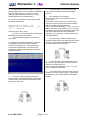
Minimailer 4
SERVICE MANUAL
SECTION 3
Service Operations
and
Adjustments
Page 3 - 1
ISSUE 3 MAR 2004
Minimailer 4
SERVICE MANUAL
3.1 PREVENTATIVE MAINTENANCE CHECKLIST
(When all items have been carried out,
worksheet must be signed to confirm).
1.
Unplug mains lead from machine.
Ensure that mains lead and its
connectors are sound and
undamaged.
3.1.1 GENERAL
2.
Remove hoppers 1 to 3 (where fitted).
3.
Upper side covers - on each cover,
raise upper section and remove 2 x
screws under lower flange and 1 x
screw at the rear, below the insert
hopper, inside the chassis plate. Lift
the cover outwards and up to clear the
lugs either side of hopper 1.
3.
LH Lower side cover - remove 2 x
screws on the top flange, hinge the
cover outwards and lift it off the 3 lugs
on the lower edge.
5.
Front vertical cover - remove both
lower side covers, then swing front
cover outwards and off (2 hinge lugs
on RH side).
6.
Electronics underpanel - remove 4 x
screws underneath envelope hopper
and spring the rear edge out from
under the hopper flange (it may be
necessary to raise the rear of the
machine slightly). To replace, note
that 3 locating lugs at the front edge
of the tray must be properly engaged
under the machine - a screwdriver
inserted underneath from the side
may assist.
1.
Ask how the machine has been
working lately and use this information
as a guide for checking the machine.
2.
Ask if there has been a change of use
e.g. high production runs or a change
of material.
3.
Check the operator adjustments of the
machine and the material being
processed.
4.
Switch on machine and observe if any
faults are reported on power-up.
5.
If necessary, generally instruct the
operators again with regard to their
specific problem area.
6.
Enter the total forms count on the
service sheet - this can be found from
‘Machine Count’ on the Supervisor
menu. Alert your service department
if the machine is being used for a
higher number than the agreed service
contract limit.
7.
When all service or repair operations
have been carried out, the machine
must be left with all parts
reassembled, leaving no risk of injury.
Note: When the side covers are removed,
subframe brackets will be seen
attached to the chassis side plates.
Removal of these (where required) is
described in the relevant section in
this manual.
3.1.2 REMOVAL OF COVERS
Note: throughout this manual, references to LH
and RH are viewed from the
envelope input end of the
machine.
3.1.3 SERVICE AT 6 MONTHS OR 100,000
INSERTS
Some or all of the following covers may
require removal for maintenance
operations. Ensure all covers are
undamaged. Check action of
opening covers to confirm correct
operation, and that safety
microswitches function correctly.
Check that all warning labels are
legible. Exercise caution with
moving parts and exposed electrical apparatus when covers are
removed.
ISSUE 3 MAR 2004
Page 3 - 2
1.
Refer to section 3.1.1 'General'.
2.
Remove all machine covers. (Section
3.1.2).
3.
Clean and inspect condition of all
rollers, jogglers, rubber transport
wheels and conveyor belts. (Section
4.3 Operating Instructions). Replace
any that are worn.
Minimailer 4
4.
Check insert separator gaps for
setting, skewing and wear (particularly
examine paper hopper separator
pads). Reset/replace if required
(Section 3.2.1/2)
5.
Check that envelope and insert feed
shafts can be removed and replaced
easily, and that the spring holds them
in place with sufficient tension.
6.
Blow dust from all sensors. (Section
4.3 Operating Instructions).
7.
Check envelope and insert side
guides for movement, stop position
and parallelism to chassis.
8.
Check all ‘T’ bearing pressure springs
are correctly located on tops of
bearings.
9.
Using an airduster, remove LH lower
side cover (Section 3.1.2) and clean
sensor disc (on main drive clutch,
bottom rear corner) to ensure that
slots are not blocked.
10.
11.
SERVICE MANUAL
master drive train in 'Clutches' to
check for proper running.
Select 'Sensors' and check the
condition of all sensors. Use the
explanations in section 3.3.2 as a
guide.
18.
Check microswitches on paper
hoppers. When any of these items
are removed, the machine should not
operate and an error message should
be displayed.
19.
Replace all machine covers and run
machine in modes normally used by
customer.
20.
Open clam shell and check that the
gas struts support the top section
when fully open.
21.
Check for wear in all bearings, replace
as necessary and lubricate. ‘T’
bearings should be lubricated with one
or two drops of light (SAE 20) oil
applied to the outside of the bearing
where the shaft passes through it.
Check free movement of finger pivots
and condition of finger tips and
springs. Replace fingers if tips are
worn or damaged.
22.
If gears run noisily, lubricate
sparingly with grease. Apply very
minimal amounts to gears in the
vicinity of the sensor disc.
On RH side lower, check condition of
finger solenoid rubber bump stops noisy running will develop if these are
perished or missing.
23.
Check security of all electrical
connectors.
24.
Visually examine flexi ribbon cables
to check for cracking or damage.
12.
Check condition of wetter tank foam
pad and wetter beam foam pad.
Replace if worn.
13.
Check solenoid plungers for smooth
action (see section 5.1 for location of
solenoids). Check that springs are in
place and undamaged.
14.
Check security of all clutch pins.
15.
Check general screw security.
16.
Check for excessive noise, squeaks
etc. and rectify where necessary.
17.
Enter Engineer Test Mode (Section
3.3).
Select 'Clutches' and 'Solenoids' and
test these components. Also run
Page 3 - 3
ISSUE 3 MAR 2004
Minimailer 4
3.2
SERVICE MANUAL
MAINTENANCE AND ADJUSTMENTS
3.2.1 PAPER HOPPER SEPARATOR GAP
The separator gap on the paper hoppers prevents
more than one sheet of paper being fed at a time.
It should be adjusted so that a single sheet is fed
when drive is engaged to the feed rollers. If double
documents are being fed, the gap may need to be
reset. To gain access to the adjustment screw,
remove the LH upper side cover (see section 3.1.2)
- the adjustors are located at the upper edge;
removal of the sub-chassis attached to the main
chassis is not required.
Remove LH and RH upperside covers (section.
3.1.2) to provide access to the separator shafts.
Also remove the relevant feed hopper(s).
To remove the separator
1.
Remove the adjustment bracket (shown in
Fig. 1) from the end of the separator pivot
shaft after unhooking the spring.
2.
On the RH side, open the clamshell and
remove the screws securing the MCU
subframe, as shown in Fig. 2 below (avoid
straining the flexi cables). This allows the
subframe to swing outwards to provide
access to the shaft ends.
The separator is located under the centre of the 3
feed rollers located at the bottom of the hoppers,
visible after removing the hopper. To set or check
the gap, wind in by hand a piece of 80gsm (20 lbs
bond) paper - a fairly firm pull should then be felt
when withdrawing the paper, though not too firm or
sheets may not feed properly. If adjustment is
required, turn the adjustment screw (see Fig. 1
below) until the correct setting is achieved. After
adjustment is complete, check the setting again to
ensure it has not moved. Note that the adjustment
screws are self-locking ‘Tufloc’ screws, and if they
are at all loose, they must be replaced.
Fig. 2
3.
Remove the 'E' clip and 'T' bearings at both
ends of the pivot shaft. Work the shaft out of
the chassis cutouts and remove it.
4.
Replacement is the reverse of removal. Set
the separator gap as previously described.
Adjustment screw
Removal of pickup roller shafts
1.
Swing open the subframe as described
above.
2.
Remove the separator (as described above)
in front of the pickup shaft being removed, ie.
for hopper 2 pickup shaft, remove hopper 1
separator. For hopper 1 pickup shaft, remove
the chassis bridge strip in front of the shaft
(2 plastic clips at each end) - avoid straining
the flexi cable. The strip need only be moved
far enough to allow the removal of the shaft.
3.
On the LH side, remove the clutch from the
end of the shaft and also the brake on the
other end. Note that no brake is fitted to
hopper 1.
4.
On the LH side, remove the two belt
tensioning jockey posts located on the
lowermost run of the belt - these have a
central screw.
Fig. 1
If, after adjustment sheets are still not feeding
reliably, or if doubles are being fed, the separator
must be replaced. The pad is glued into the
separator arm, and both must be replaced as an
assembly. Do not attempt to replace the pad only.
Note: the pick-up roller above the pad is more
likely to wear than the pad itself - if the pad is worn
out, the pick-up roller probably is also, and should
be replaced at the same time. The procedure for
any of the 3 hoppers is the same, and is described
on the following page.
ISSUE 3 MAR 2004
Page 3 - 4
!
Minimailer 4
5.
Remove the feeder-loaded sensor for the
relevant shaft. This is located inside the
chassis bridge above the shaft, retained with
a single screw on top of the bridge. Also
remove the hold point sensor (located
between 2 of the feed rollers) by unclipping it
from its holder.
6.
Remove the XL pulley from the end of the
shaft after lifting the drive belt clear. Take
care not to displace the dowel for the clutch.
7.
Remove the 'E' clips and 'T' bearings from
the ends of the shaft and work it out of the
chassis through the slots in the sideplates.
8.
Replacement is the reverse of removal. Set
the separator gap as previously described.
3.2.2 INSERT HOPPER SEPARATOR GAP
The insert hopper has two adjustments, one for the
separator gap, the other for the tension of the plate
holding the separator pads. The separator plate is
located below the insert hopper. To gain access,
lower fold plate 1 under the hopper and open the
clamshell. Remove the 4 countersunk head screws
holding the upper part of the foldplate and lower it
down. The separator plate is shown in Fig. 3 below
(viewed as from directly underneath).
Separator tension nuts (2)
Separator gap screws (2)
Fig. 3
SERVICE MANUAL
Separator gap
The gap should be set so that when looking down
the insert hopper tray, the tops of the separator
pads are aligned with the bottom of the pickup
rollers, as shown in Fig. 4 below. If adjustment is
required, equally turn the separator gap screws
shown in Fig. 3 until the setting is correct.
Separator pads
Fig. 4
Separator plate tension
The separator plate is held under slight tension to
allow lightweight inserts to be fed without doubles,
and if a thick insert (such as a booklet) is fed, the
plate will flex sufficiently to allow it through. The
tension is factory set at 5N on top of the separator
pads, which can only be determined using a force
gauge. Therefore, should the plate require
retensioning (after replacement, for example),
proceed as follows:
1.
Set the separator gap as previously
described.
2.
Slacken the 2 nyloc nuts so that there
is clearance between the face of the
nut and the separator plate.
3.
Tighten the nut until a small piece of
80gsm paper is just gripped between
the face of the nut and the separator
plate.
4.
Remove the paper and tighten the
nuts a further 4 flats (approx. ¾ turn).
This will provide a starting point to test whether
further small adjustments are required. The machine should be able to feed lightweight inserts and
a 1.5mm thick booklet without doubles. If doubles
are occurring, the plate may need further tension. If
a booklet will not feed, it may need less tension.
Separator plate replacement
If the pads are worn, the separator plate assembly
must be replaced, due to the pads being permanently glued to the plate. To replace, proceed as
described on the following page:
Page 3 - 5
ISSUE 3 MAR 2004
Minimailer 4
SERVICE MANUAL
1.
Remove the 4 csk screws and hinge down
fold plate 1, as described previously.
2.
Remove all screws and nuts marked * in Fig.
5 below. Note that the rearmost screw posts will
require removal to gain access to 2 of the screws.
3.2.3 ENVELOPE HOPPER SEPARATOR
The envelope hopper separator is different from the
insert hopper by not having a tension adjustment,
and by having a downward bias, so gap adjustment
is by means of 2 Nyloc nuts to move it upwards.
Separator gap adjustment
To adjust the gap, withdraw the electrics chassis
(see section 3.1.2). As an initial setting, visually
align the tops of the pads with the bottom of the
pickup rollers, as shown in Fig. 4. Then adjust the
nuts 'A' shown in Fig. 6 below (viewed from directly
underneath the plate) until an envelope will firmly
drag as it is passed through the gap.
Fig. 5
3.
Remove the nut securing the bracket
for the hopper loaded sensor and
move the bracket out of the way.
Withdraw the plate assembly and
strip off the guide rack plates and
pinion.
4.
Replace the new plate in reverse order
to removal after fitting the rack and
pinion. Note that the sensor bracket
should be reasembled while the plate
is still loose, or access may not be
possible. The gap adjustment screws
must be fitted after the plate is
assembled in place - use Loctite 221
threadlocking adhesive on the
threads.
5.
Fig. 6
Separator plate replacement
If the pads are worn, the separator plate assembly
must be replaced, due to the pads being permanently glued to the plate. To replace, proceed as
follows:
Reset the gap and plate tension as
previously described.
1.
Remove the nuts marked 'A' & 'B' and
the screws marked 'C' in Fig. 6 above.
Withdraw the plate and strip off the
guide rack plates and pinion.
2.
Replace in reverse order to removal
after fitting the rack and pinion and
refit the electrics chassis (see section
3.1.2).
Envelope feed shaft for narrow envelopes
Optional feed shaft A3251A is available for narrow
envelopes, such as C6. This omits the outer roller
at each end, allowing the side guides to be moved
closer together. The envelope feed shaft springs out
of place for removal - ensure that the drive pin is
properly engaged when replacing.
ISSUE 3 MAR 2004
Page 3 - 6
Minimailer 4
SERVICE MANUAL
3.2.4 DRIVE BELT REPLACEMENT
There are 5 drive belts on the Minimailer 4 - one
each on the RH upper, RH lower and LH lower
sections, and two on the LH upper section. There
is also one in fold plate 1. To replace any of them,
the appropriate side cover must first be removed
(see section 3.1.2), then proceed as follows:
LH Lower section (1 drive belt: 300 XL 037 F5023A)
1.
Remove only the subframe screw indicated
in Fig. 8 below - this will allow the end to
spring sufficiently to allow belt removal under
the bracket.
LH Upper section (2 drive belts: 510 DXL 037 F5125A & 448 DS2M - F5084A)
1.
Remove all screws securing the black
subframe, leaving wiring undisturbed. Also
remove the two plastic rivets at the front,
securing the wiring bridge.
2.
Main drive belt: Referring to Fig. 7 below,
remove the idler and clutches indicated, and
also the nylon gear. Note that access to the
idler screw will be eased by removing the
clutch on hopper 1 feed shaft; this will allow
the subframe to be moved upwards. Lifting
the subframe as required, remove the belt
(note that one sensor cable may have to be
disconnected to release the belt).
3.
Fit the new belt following the route shown
and refit the idler, gear and clutches.
Clutch
Clutch
Fig. 8
2.
Remove the clutch, idler and gear with 'E'
clip indicated in Fig. 9 below, and also unclip
the Distribution board from its mounts.
Remove the old belt under the raised
subframe backet and fit the new one. Replace parts in reverse order to removal.
3.
Refit the subframe ensuring the flexi cable is
stuck back onto the bottom edge and
secure all cables using cable ties as required.
Clutch
Idler
Gear with 'E'
clip
Clutch
Idler
Idler
Fig. 9
Clutch and
nylon gear
Fig. 7
4.
Insert feed drive belt: Referring to Fig. 7
above, remove the clutch and idler indicated.
Remove the belt.
5.
Fit the new belt and refit the idler and clutch.
6.
Refit the subframe securing cables with new
cable ties as required.
!
Page 3 - 7
ISSUE 3 MAR 2004
Minimailer 4
SERVICE MANUAL
Fold Plate 1 (1 drive belt 100 S2M - F5111A)
RH Upper section (1 drive belt 560 S2M F5072A)
1.
Swing open the MCU subframe as shown in
Fig. 2.
2.
Referring to Fig. 10 below, remove the
clutches and idler indicated.
3.
It is now possible to remove the old belt in
the gap between the end of the upper shaft
and the black subrame without disturbing
the subframe. Fit the new belt, positioning it
over the lowest pulley first.
4.
1.
On the upper RH side, swing open the MCU
subframe as shown in Fig. 2.
2.
Lower fold plate 1 under the insert hopper
and open the clamshell. Remove the 4
countersunk head screws holding the upper
part of the foldplate and lower it down. The
drive belt is now visible under the hopper.
Idler
Clutch
RH SIDE
LH SIDE
Idler
Refit the clutches and idler and re-attach the
subframe. Ensure the clutch bodies have
properly located on the lugs.
Clutch
'E' clip &
bearing
Fig. 12
Clutch
3.
Referring to Fig. 12 above, on the LH side
remove the clutches and idler indicated and
take off the belt. Remove the 'E' clip and
bearing, and on the upper clutch shaft,
remove the drive pulley, 'E' clips and bearing
- note that there are 2 'E' clips at this location.
4.
Remove the black cover under the side cover
by removing the two screws at the lower
edge, and slackening the screw near the
middle - note that slots allow it to lift off.
On the RH side, remove the clutches and
idler indicated and take off the belt. Remove
the 'E' clip and bearing, and on the upper
clutch shaft, remove the drive pulley, 'E' clips
and bearing.
5.
Referring to Fig. 11 below, remove the
tension idler indicated and take off the old
belt. Fit the new item and replace all parts in
reverse order.
With both ends of both shafts now free, draw
the RH ends out through the chassis sufficiently to allow the belt to be taken off at the
LH ends.
6.
Fit the new belt and reassemble in reverse
order to removal. Refit the MCU subframe.
Idler
Clutch
Fig. 10
RH Lower section (1 drive belt S2M 322 F5145A)
1.
2.
Idler
Fig. 11
!
ISSUE 3 MAR 2004
Page 3 - 8
Minimailer 4
SERVICE MANUAL
3.2.5 FOLD ROLLER REPLACEMENT
There are 4 fold rollers on the Minimailer 4 - three
are identical (rollers 1, 2 & 4 in Fig. 13 below),
roller 3 is the driving roller and has a longer shaft.
All rollers are the same diameter. If any have to be
replaced, they should all be replaced together as a
set.
Fold roller 1
3.
Remove the transport assembly under the
clamshell by lowering the assembly, then
taking out the pivot screw each side. On the
RH side, the cable guard plate will also need
to be removed. As the assembly is withdrawn, disconnect the sensor lead each
side. Support the assembly on the closer,
avoiding strain on the flexi cables. With the
assembly now free, access can be gained to
the lower rollers.
4.
Remove No. 3 separator shaft (see section
3.2.1).
5.
Detach the spring-loaded feed shaft from the
insert hopper and withdraw, but do not
remove, the black infeed plate in front of the
shaft. To do this remove the screw each side
at the top corners (on the LH side, the pulley
will need to be removed to access the
screw) and pull the plate backwards slightly.
Only sufficient clearance for roller removal is
required.
6.
Remove all gears, 'E' clips, drive pins, 'T'
bearings/springs and roller bearings from
both ends of all four fold rollers. On fold roller
2 RH side, also detach the end of the no-fold
spring hooked over the edge of the 'T' bearing cutout. This is located as shown in Fig.
15 below.
Fold roller 2
(with no-fold beam)
Fold roller 4
Fold roller 3
Fig. 13
Removal of the rollers is a fairly extensive task, but
can be accomplished without completely removing
the upper subframes under the side covers. The
procedure is described below:
1.
On the upper RH side, swing open the MCU
subframe as shown in Fig. 2, and on the
black subframe below, remove the screws
indicated in Fig. 14 below, but do not remove
the subframe. Note that the flexi cables
must be unclipped to access the 2 countersunk screws on the outside face.
Fig. 14
2.
Remove LH & RH upper drive belts (see
Figs. 7 & 10).
Note: Further operations may require the
removal of various 'E' clips, gears, clutches,
etc. as required - these will not be specifically
described, but assumed.
End of no-fold
beam wrap
spring
Fold roller 2
Fig. 15
7.
Work roller 1 out of the chassis, then roller 2
with the beam attached - note that the
chassis may need slight 'springing'.
8.
Remove the remaining rollers similarly, either
from above or below.
9.
Fit the new fold rollers after changing over
the no-fold beam. Reassemble all parts in
reverse order to removal, noting the following
points:
•
the 'T' bearing springs are located
thus: green spring (light) - No. 1 roller.
Yellow spring (medium) - No. 2 roller.
Red spring (heavy) - No. 4 roller.
•
the end of the no-fold spring must be
hooked over the 'T' bearing cutout
before assembling the bearing. Use
long pointed pliers.screwdriver to
locate it.
Page 3 - 9
ISSUE 3 MAR 2004
Minimailer 4
SERVICE MANUAL
if any flexi cables have become
unstuck from the chassis, stick them
back using new double-sided tape.
Closer Belt
7.
On the LH side, ensure the drive belt is
removed, as described at step 2.
•
ensure the sensors for the transport
assembly are reconnected.
8.
•
ensure that dowel pins for gears are in
place.
•
when reconnecting cables to Distribution board 1, note that connector
numbers are marked.
Remove pulley, 'E' clips, drive pin and 'T'
bearings from both ends of upper and lower
shafts indicated in Fig. 16. Note that the
green knob and gear on the RH side need
not be removed.
9.
On the RH side, remove the screw retaining
the guide plate (below the green knob) and
slide the plate out.
10.
Remove the tension shaft screws (1 each
end, 2 on front face).
11.
Raise the front of the machine and remove
the lower roller and tension shaft from below.
Lift out the upper roller and withdraw the
belts from above.
12.
Fit the new belts and all other parts in
reverse order to removal.
•
3.2.6 CONVEYOR BELT REPLACEMENT
There are two pairs of conveyor belts on the machine, one located at the infeed area, the other at
the closer. If the belts are ragged, damaged or
glazed, they may require replacement. This will
require the removal of the LH lower cover, and
hinging down the RH cover. Also remove the black
cover on the RH side (2 screws at the bottom
edge, 1 screw near the centre on the inside), then
proceed as follows:
Closer belt
Tension shaft
Fig. 16
Insert belt
1.
Remove the front underpanel by taking out
the 3 screws either side at the lower edge
and removing the panel, with attached
envelope tray, after lifting the front of the
machine up.
2.
Remove the LH lower drive belt (see Fig. 8).
Insert Belt
3.
Remove the solenoid bracket on the RH side
to provide access to the end of the roller
shaft (it need not be taken fully off).
4.
Remove gear, pulleys, 'E' clips, drive pin and
'T' bearings from both ends of both shafts
indicated in Fig. 16 above.
5.
Raise the front of the machine and work the
shafts and belts out of the chassis from
below. Fit the new belts and replace the
shafts.
6.
Refit all parts in reverse order to removal.
ISSUE 3 MAR 2004
Page 3 - 10
Minimailer 4
3.2.7 INSERT TRANSPORT ROLLERS
The insert transport shaft is located on the insert
hopper after the spring-loaded feed shaft. The
rollers feed the insert down to hold point position,
and then hold it until the insert is clear to feed. The
shaft carries 4 rollers, and a sprung roller shaft is
located in a plate assembly just above it - this
presses on the drive rollers to provide traction.
SERVICE MANUAL
Removal of transport plate assembly (see Fig.
18 below) - viewed from front of machine with feed
hopper removed.
Transport plate assembly
If feed problems such as excessive skewing or
slipping are occurring, the rollers may need replacement. This will involve removal of the transport
roller shaft, and also the transport plate assembly.
Removal of transport roller shaft
1. Remove the LH and RH upper side covers
(section 3.1.2).
2. On the RH side, swing open the MCU subframe
(section 3.2.1).
3. Remove the lower shaft for fold plate 1 drive
belt, as described in section 3.2.4, 'Fold Plate
1' on page 3-8. Ignore all steps relating to the
upper shaft - this need not be removed, nor the
drive belt (see Fig. 17 below).
S2M
pulley
LH SIDE
Upper fold
plate shaft
Transport
roller shaft
Lower fold
plate shaft
Fig. 17
4. Remove 'E' clips and 'T' bearings at both ends of
the transport roller shaft and remove the shaft
from the chassis.
5. Refit the new shaft and all other items in reverse
order to removal.
Fig. 18
1. Undo all screws retaining the black subframe on
the LH side and slide off the S2M pulley shown
in Fig. 17 (the subrame will move sufficiently to
allow this).
2. Remove the separator shaft for hopper 3, as
described in section 3.2.1.
3. Remove the screws retaining the posts at the
upper corners of the transport plate assembly.
4. Unplug the flexi cable for the two sensors on
the plate assembly - this connects to CONN C
on Distribution board 5 on the RH side (upper
left connector). Lead the cable through the hole
in the chassis side plate so that it is inside.
5. Pull the assembly rearwards to free the lower
edge and withdraw it. Note that the plate can
now freely hinge open, and the springs for the
roller shaft will be loose.
6. The roller shaft in the plate assembly can now
be replaced after removal of the 'E' clips.
7. Refit all items in reverse order to removal.
Page 3 - 11
ISSUE 3 MAR 2004
Minimailer 4
SERVICE MANUAL
3.2.8 OMR HEAD ADJUSTMENTS
When an OMR head is fitted, it can be attached
anywhere across the width of the machine to suit
the stationery being processed. Its position can
later be changed if required, as described later in
this section. The head is mounted on a springloaded block which is adjustable to provide the
correct gap between the head sensor and the
rubber roller. Additionally, the head must be
correctly aligned widthways to ensure that the
centre of the OMR sensor is in line with the centre
of the marks on the paper. The assembly as
shown in Fig. 19 below attaches to a special roller
carrier which replaces one of the standard carriers
on the machine.
1.
Remove the upper side covers and the front
cover (in front of hopper 1) - see section
3.1.2.
2.
Referring to Fig. 19 below, slide a piece of
80gsm (20lbs bond) paper between the
sensor face of the OMR head and the rubber
roller - the paper must not be under the
roller on the adjustment plate. Slacken the
adjustment screw to allow the head block to
move in and out against spring pressure.
Ensuring that the paper is a sliding fit
between the sensor face and the rubber
roller, and that the roller of the adjustment
plate is contacting the rubber roller, tighten
the screw. Carefully check the setting to
ensure that the paper is still a sliding fit, or
slightly tight. Note: due to a certain
amount of backlash in the moving parts,
using a single sheet of paper is likely to
result in too small a gap, or no gap at all. It
may be found when setting that using 2, or
even 3 sheets of paper will result in a correct
final gap.
To adjust the head gap
If the head position has been changed (see later in
this section) or if bad OMR reads are being encountered, the head gap may need adjusting. This
gap should be no more than 0.1mm (.004”), equivalent to a single sheet of 80gsm (20lbs bond) paper.
The adjustment procedure is described below:
OMR head
Retaining peg
Sensor face
Adjustment plate
Slide pin
Adjustment screw
Head block
Fig. 19
!
ISSUE 3 MAR 2004
Page 3 - 12
Minimailer 4
SERVICE MANUAL
To align the head with the marks
The sensor contained within the OMR head must
align with the centre line of the marks on the paper.
As the sensor is not centrally located inside the
head, it must be offset slightly, as shown in Fig. 20
below. The sensor is approximately 7.5mm (0.3”)
from the non-cable side of the head, and this is the
position that must be aligned with the centre line of
the marks.
To adjust, first remove both upper side covers and
the front cover, if not already removed. Slacken the
lock screw under the roller carrier and slide it on
the rod to suit, using a ruler to measure the sensor
position. Lock the screw when adjustment is
complete.
Approx.
7.5mm (0.3”)
To move the OMR head to another carrier
position
The carrier holding the OMR head is different from
the others, and hence the OMR pressure shaft will
have to be removed. First remove the OMR head
from the retaining peg and support it avoiding strain
on the cable. Referring to exploded view section
4.6, remove the ‘E’ clips, ‘T’ bearings and springs
supporting the OMR pressure shaft (item 3) and
take out the shaft, complete with carriers. Strip
down the assembly as required and reassemble
with the OMR head carrier in the required position.
Refit the shaft in reverse order to removal, and
adjust the OMR head gap and alignment as previously described.
When changing the OMR head position, it may be
necessary to lengthen or shorten the cable to suit.
The cable is looped in retaining clips along the front
edge of the machine and should removed from the
clips, looped up again to suit the required length
and clipped back into place. The connector plugs
into J5 on the MCU board.
When all adjustments are complete, refit all covers
and test run the machine to ensure that the marks
are being read correctly.
Setting up the OMR head
Fig. 20
To change the OMR head position
The OMR head can be positioned anywhere across
the width of the paper, and if the marks cannot be
reached by sliding the carrier, the head position
can be changed in one of two ways:
a)
By changing the OMR head to the
other side of the sliding head block.
b)
By moving the OMR head to a different carrier position.
When the head has been attached and aligned as
previously described, it will require setting up to
ensure consistent reads. This is carried out in
Engineer Mode, using a piece of representative
marked paper. Proceed as described below:
1. Enter 'Sensors' in Engineer Mode and carry out
an Autocalibrate.
2. Scroll down to 'OMR' in Sensors, as shown
below:
To move the OMR head to the other side of the
carrier, refer to Fig. 19. Slacken the screw under
the OMR head and slide it off the retaining peg.
Slacken the grub screw in the end of the sliding
head block and remove the retaining peg. Move
the peg to the other side of the block and reassemble all parts in reverse order, ensuring that the edge
of the OMR head is located firmly under the flange
of the head block. Adjust the gap and position as
previously described.
!
Page 3 - 13
ISSUE 3 MAR 2004
Minimailer 4
SERVICE MANUAL
3. Scroll the OMR setting up or down until it reads
20.
4. Load OMR marked paper into hopper 1 and
open the clamshell. Using the lowermost gear
on the LH side, wind in the paper by hand so
that a white area is under the head.
5. Increase the setting until the display changes
from cl (clear) to bl (blocked), then add 3. White
will then be correctly indicating as blocked (ie.
paper present).
6. Wind the paper in further and check that the
display changes from bl to cl as the mark is
read (cl should also indicate a higher reading
after the decimal point than bl).
7. The head is now set up. Test the machine on an
OMR job to check if it is working correctly. If
misreads occur, return to the setting and
increase it by steps of 1 until reading is correct.
If it is not possible to correct the misreads, test
the head as described below.
Fault Finding & Testing
If problems such as bad reads or no reads are
being encountered, the signal from the OMR head
can be analysed using a PFE OMR Scope, part
number 184-415, and a PC or laptop. This provides
an on-screen trace of the head signal and indicates
whether the head is reading the marks correctly.
ISSUE 3 MAR 2004
Full instructions for using the OMR scope are
provided in OMR Scope User Manual, part number
K2023A. A number of cables are included with the
scope, and a scope adaptor will also be required,
as shown below in the connectivity diagram. Note
that if your computer only has a USB port available
instead of a COM port, USB adaptor 179-746 will
be required (not included with the Scope).
Page 3 - 14
Minimailer 4
SERVICE MANUAL
3.2.9 FINGER ADJUSTMENT
The finger positions are factory set and for most
purposes should not normally require adjustment.
The width across the outer fingers is set to 212mm
(slightly greater than A4) for European machines
and 217mm (slightly greater than Letter) for US
machines, as shown in Fig. 21 below:
If forms of a different width are being fed, the outer
fingers must be adjusted to suit - open the clam
shell to gain access. Slide the fingers on the shaft
to suit (note that they should be a tight fit). The
width across the tips should always be slightly
greater than the form width by 1 - 2mm, and the
fingers must be centrally disposed about the centre
line of the machine. Note: when collating in the
envelope for multiples, the outer fingers may need
to be adjusted further out by up to 3mm in order to
pull the throat futher open. The exact setting will
depend on the type of stationery being used.
The inner fingers should always be set inboard as
far as possible. If narrow envelopes are being used
such that the envelope width would be inboard of
the outer fingers, these are left in place but ignored. Instead, the inner fingers should be
swapped over, as shown in Fig. 19, and adjusted
as described above for the outer fingers.
Note that the fingers are fitted with a peg inside the
clip which runs in a groove on the carrier bar, hence
they cannot rotate on the bar.
Fig. 21
3.2.10 INSERT PINCH ROLLERS
The pinch rollers are located in the insert area,
carried in a removable beam. They press against
two of the four rollers on the shaft above and grip
the flap of the envelope as it passes between them
and the 4 rollers. If the flap is not being gripped
sufficiently, either the 4 rollers or the pinch rollers
may need replacing.
To replace the pinch rollers, proceed as follows:
1.
Remove the LH side cover (see section
3.2.1) and also the subframe (see Fig. 9).
Beam retaining
screw
Cover retaining
screw
2.
Referring to Fig. 22 below, remove the beam
by taking out the screw on the LH chassis face.
Push the beam sideways slightly to clear the tangs
and lift it out of the chassis. Note: avoid straining
the flexi cable to the sensor. To separate the cover
from the beam, remove the 2 screws shown.
3.
Remove the nut securing the pinch roller
assembly. Note that the assembly must be replaced complete.
4.
Refit all parts in reverse order to removal.
Pinch roller assy.
Fig. 22
Page 3 - 15
Cover retaining
screw
ISSUE 3 MAR 2004
Minimailer 4
3.2.11
SERVICE MANUAL
PAPER JAM CLEARANCE
Due to the design of the machine, the Minimailer 4
does not readily jam. Any jams that do occur are
most likely to happen in the fold rollers when an
insert is being nested, and an excessive folded
pack thickness results in the rollers jamming
solidly. Use of the green knob may then not help,
as the fold roller gears will spring out of mesh.
Such a jam can be cleared by using the following
procedure:
1. Switch off the machine.
2. Remove hopper 3 to provide access to the top
fold roller.
3. Raise the clamshell and locate the metal main
drive gear, on the LH side at the lowest point near
the rear. Wrap a suitable cloth or rag round the
gear and turn it by hand while pressing down on
the top roller roller to stop the gear springing. The
jammed documents will then be wound into either
fold plate 1 or 2, depending on the direction the
gear is turned.
Note also that the transport plate under hoppers 1
and 2 can be lowered by pulling in the springloaded handle in the centre recess. This is another
possible, though less likely, area for paper jams.
3.2.12 FLEXI CABLES
All sensors and components on the machine are
connected to one of the five distribution boards
using flexi cables. The distribution boards and the
display are all connected to the MCU board, again
using flexis.
surfaces using double-sided adhesive tape. When
replacing use new double-sided tape - the
adhesive strength of used tape will not retain the
cable sufficiently, and it may come free and become caught in mechanism.
There are 20 separate flexi cables on the machine,
most branching into smaller cables to connect to
more than one termination. If a cable becomes
damaged, repair is not possible - the whole flexi
must be traced back to its origin and replaced.
The ends of the flexis are retained in special
connectors on the circuit boards. To free a cable,
do not just pull it out - pull the top edge outwards
to unclip the cable end. Replace in a reverse
manner.
Flexis are supplied ready folded, and with their
identity and terminations marked on them. In most
cases, they are retained to chassis and other
The full list of flexi cables is shown below. Use this
list in conjunction with the wiring diagram shown in
section 5.8.
Identity
FS01
FS02
FS03
FS04
FS05
FS06
FS07
FS08
FS09
FS10
FS11
Part Number
182-591
182-592
182-593
182-594
182-595
182-596
182-597
182-598
182-599
182-600
182-601
FS12
FS13
FS14
FS15
FS16
FS17
FS18
FS19
FS20
182-602
182-603
182-604
182-606
182-605
182-607
182-629
182-630
182-631
ISSUE 4 MAR 2006
Connection
MCU to Display Board (Switch)
MCU to Display Board
MCU to Distribution Board 1 J17
MCU to Distribution Board 1 J16
MCU to Distribution Board 1 J15
MCU to Distribution Board 2 J13
MCU to Distribution Board 2 J14
MCU to Distribution Board 3 J12
MCU to Distribution Board 4 J11
Distribution Board 1 J11 to Sensors
Distribution Board 1 J10 to Sensors &
Distribution Board 5 Conn A
Distribution Board 1 J8A to Sensors
Distribution Board 1 J9 to Sensors
Distribution Board 2 J6 to Sensors
Distribution Board 2 J5 to Cover Switches
Distribution Board 3 J11 to Hopper Switches
Distribution Board 4 J5 to Disk Sensor
Distribution Board 5 Conn C to Sensors
Distribution Board 5 Conn B to Sensors
Distribution Board 1 J8B to Sensors
Page 3 - 16
Minimailer 4
3.3
SERVICE MANUAL
ENGINEER MENU
The Engineer function allows components such as
motors and solenoids to be tested, sensors to be
set and provides voltage and current readings for
power sources. It also provides a number of other
functions, all of which are described here.
To access the Engineer menu, the PIN must first
be entered. Use the Scroll Up/Down buttons to
select each number, then press the Enter button to
move to the next. Press the Exit button when all
three numbers are entered. The menu will then be
displayed:
Software version is a read-only display. Note that
software is upgradeable either by insertion of a new
eprom or by a flash download.
Language for the Menus and Help may be
changed to one of five languages.
Display contrast can be changed if required
between 0 and 63. Default is 50.
Feeders determines whether feeders 1, 2 & 3
default to on or off at startup. These states can be
changed in Create/Edit Job.
Power provides a read-only display of voltages and
currents of various supply sources. The voltage and
current readings are displayed to two decimal
places, and 'AC motor speed’ enables the drive
motor to be switched on or off, and the RPM
observed. Note that due to the gearing, this figure
must be multiplied by 3.
Clutches and Solenoids allow you to switch these
components on or off to test them and provide a
readout of current rating. The whole drive train can
also be switched on or off.
Sensors: There are three types of sensors fitted, a)
proximity sensors (eg. Feeder x Loaded) which are
only reported as blocked or clear, b) digital sensors
which are adjustable, and will display 0 for clear, 1
for blocked, and ADC sensors, also adjustable,
which display a 4 digit indication of the TX/RX
correlation in units from 0 to 1023. A blocked
sensor will give a higher reading than a clear
sensor, with a threshold of about 256. Generally, a
clear sensor should not be too close to the threshold. If the value is close to zero, this indicates a
short to ground rather than just a permanently lit
sensor.
The first two digits represent the intensity of the
emitter in units from 0 to 63. To set the sensor at
service intervals, clear the machine of paper. For
each sensor, press Enter, then use Scroll Down
button until the sensor shows blocked, then Scroll
Up until it shows clear, plus 3 further presses.
When done, press the Exit button.
Encoders are the slotted (top hat) sensors on the
finger operating arm, and the slotted disc on the
drive motor. The read-only display reports whether
clear or blocked.
Interlocks are the safety reed switches for
clamshell or cover, and the location switches on
the hopper trays. The read-only display reports
their state.
Tolerances relate to acceptable limits of insert
and envelope depths, both upper and lower, and are
adjustable. Units equate to 0.41mm. Defaults are
±10 for inserts, ±2 for envelopes, so for an insert of
nominally 100mm depth, 95.9 - 104.1mm would be
accepted.
!
Page 3 - 17
ISSUE 3 MAR 2004
Minimailer 4
SERVICE MANUAL
Soak test runs the machine, exercising clutches
and solenoids. Clear the machine of stationery
prior to running.
envelope deskew only if required - +ve means
deskew is increased
Calibrate allows adjustment of lengths, positions
etc. as measured by the machine. This compensates for any errors due to machine tolerances.
Units equate to 0.41mm. The meaning of positive/
negative is as follows:
Clutch overlaps relate to the time period that a
clutch and its corresponding brake are on simultaneously. Units are in millisecs, defaults shown
below. Alter with care to avoid strain caused by
excess overlap. All settings are a starting point,
and are for 220v or 110v.
All lengths:
All collates:
Envelope position:
Wetter position:
Closer position:
All deskews:
All advances:
+ve = longer
+ve = closer to leading edge
+ve = later at insert position
+ve = earlier, ie. more flap
wetting
+ve = moves forward to
eject earlier
+ve = more deskew
+ve = more advance
If the machine is to be completely reset, use the
following initial settings (items marked * are a
starting point, others are usually constant). All
settings are for 220v or 110v unless otherwise
indicated.
Form 1 Length
Form 2 Advance
Form 2 Collate
Form 2 Length
Form 3 Collate
Form 3 Length
Insert Deskew
Insert Advance
Insert Collate
Insert Length
Envelope Deskew
Envelope Length
Envelope Position
Fold 1 Length
Fold 2 Length
Wetter Position
Envelope Closer
F/Plate 2 Delay
Env. @ Ins. DS
-62
-24*
-48
-6
15
-5
0*
0 for 220v, -30 for 110v
-11
-3
30*
5
-13
-3
-28
-20*
25*
50*
35*
Use Stack 'n' Go to run form from hopper 1. When
machine stops for check, enter 'Edit Job' and
check measured length against actual length adjust if required in Calibrate (select Save & Exit to
leave Stack 'n' Go). With length now correct, repeat
for fold lengths, adjusting as required. Repeat this
prcedure for hoppers 2 and 3, and also check edge
alignment when collating, including inserts. Check
envelope position at insert by using Job Mode to
'walk' through cycle (see Operating Instructions,
section 3.9) - flap crease should be in line with
centre of small pinch rollers. Adjust insert or
ISSUE 3 MAR 2004
Feeder 2
Feeder 2
Insert Deskew
Env. Deskew
Env. Position
Foldplate 1
Foldplate 2
Env. Closer
10*
10*
15*
10*
10*
1*
1*
1*
Optimizations control settings that allow the
machine to run at maximum possible speed.
'Envelope pre-feed' allows an envelope to be fed to
deskew position while the preceding one is still at
insert, so minimising delay. 'Envelope track trigger'
feeds an insert when the track sensor is triggered
by an envelope. Both these settings should only be
turned off if special circumstances require the
machine cycle to be slowed.
Feeder delay settings advance or retard the point
at which the sheet or insert is fed and is used to
'fine-tune' the optimimum performance. Units are in
approx. 0.5millisec steps. Defaults are as shown
above and should not normally require adjusting.
Page 3 - 18
Minimailer 4
3.4 FIRMWARE UPGRADING
SERVICE MANUAL
Transfer link from OP (Operational) mode to ISP
(In System Programming) mode.
The firmware is stored in:
1.
2.
Internal flash memory of the microprocessor
External flash memory devices on the MCU
You will require two utilities for the upgrading
process, MC-16C Flasher and MiniFlash. These
can be obtained from Technical Support or the
PFE website. You will also require a serial cable
(PFE part no. 182-194) and a PC.
Important: On most occasions it will only be
necessary to upgrade the internal memory, in
which case the procedure should be started at
step 7, bypassing the programming of the external
memory. In the event that external memory needs
upgrading also, the procedure should be started
from step 1. See the note in step 6 for details of
determining which procedure should be used.
2.
Power up the machine - it will now in InSystem-Programming mode. The display will be
blank and all LEDs will be in the off state. Don’t
get alarmed, this is perfectly normal. On the PC,
make sure that Hyperterminal and any other
communications application which might be using
a serial port is closed down.
3.
Run the M16C Flasher Utility program. You
should see a screen similar to below:
Method
Board Programming Sequence. Refer to drawing
below for the location of the serial connector and
the board link position.
1.
With the Mini 4 Plus switched off, plug the
serial cable from the PC into the 9 way D-Type
connector located centre right of the board.
NOTE: The very first time MC-16C Flasher is run
you will need to set up the COM port settings. To
do this click on [Settings] button and select the
COM port you are using and a baud rate of
115200. All other settings can be left as default
(as shown if following image). Press the [Close]
button and these settings will be stored in your PC
and you shouldn’t need to do this again.
Page 3 - 19
ISSUE 3 MAR 2004
Minimailer 4
SERVICE MANUAL
A. The status should now say COM1 Ok (if you
had selected COM1). If an error status is reported
then the COM port may not exist on your PC
(select another COM port) or may be in use by
another application (close application).
B. Click [Connect] button. After a few seconds
the status should show:
Connecting at 115200 ... Ok
Reading version information ... Ver
3.02 ... Check Ok
If the connection fails, check
(i) Link L1 is in the ISP position and that the
Mini4 Plus has been power cycled.
(ii) Serial cable is properly connected at
both ends.
C. Click [Program] button and select a file from
the dialog box - the file required for external
memory is Extmem2.mot. If all goes well, the
progress bar at the bottom of the window will
progress to completion and the status should be
reported as below:
5.
Power up again. The microcontroller will
now only allow uploads to the External Flash
memory.
6.
Run Miniflash.exe as follows:
Press ‘Select Options’ and select the correct
comms port.
Press ‘Start’ - the record counter at the bottom
right of the screen should now increment rapidly.
Wait for ‘Upload complete’ message.
The file you will be uploading is ext_x.x.x.x.m4e.
Note: if the third 'x' of this file (ie.ext_x.x.x.x.m4e)
is a higher number than the existing firmware, then
both internal and external memory will need
upgrading. If it is the same, only internal memory
need be upgraded.
7.
Once the external flash programming is
complete, OR if you are only upgrading the internal
memory, power down, and transfer the link from
OP mode to ISP mode once again.
8.
Power up and run the M16C Flasher utility
in order to program the microcontroller with the
code for running the machine.
The file you will be uploading is int_x.x.x.x.mot
Once completed, power down.
4.
Once this code is programmed into the
microcontroller, close M16C Flasher, power down
the Mini 4 Plus and transfer the link from the ISP
mode to the OP mode.
ISSUE 3 MAR 2004
9.
For the final time, transfer the link from ISP
mode to OP mode, power up again. The machine
should now run as normal with the new firmware
loaded.
Page 3 - 20
Minimailer 4
3.5
SERVICE MANUAL
RECOMMENDED SPARES LIST
The following spares are recommended to be held
by Service Agents. A complete set can be obtained by ordering part number A0321A (covers
both 220v and 110v machines).
Quantities stated are per 5 machines.
Part No.
Description
Qty.
Mechanical Spares
A2456A
A2457A
A2463A
A2472A
A2757A
A2782A
A2890A
Finger Assy. RH
Finger Assy. LH
Disc Hub Assy.
Insert Roller Assy.
Wetter tank Assy.
Separator Assy.
OMR Head Kit
2
2
1
2
1
3
1
B0114A
Collate Spring
2
C2653A
C8098A
C8142A
C8143A
C8144A
C8146A
C8147A
C8148A
C8149A
C8157A
C8158A
C8159A
C8161A
C8162A
C8163A
C8164A
C8165A
C8170A
C8172A
Envelope Feed Bearing
Roller, Envelope Feed
Fold Roller, 30mm Dia.
Fold Roller, 25mm Dia.
Shaft, Sheet Feeder
Shaft, Envelope Flap
Shaft, Opener Eject
Shaft, Opener Infeed Pressure
Insert Roller Shaft Assy.
Shaft, Roller Closer
Shaft, Flapper Input Drive
Shaft, Fold Plate 1 Lower
Shaft, Fold Plate 2
Shaft, Insert Stage
Shaft, Transport
Shaft, Pressure Roller
Shaft, Envelope Transport
Roller, Seal
Shaft, Insert Infeed
2
6
1
3
3
1
1
1
1
1
1
1
1
1
1
2
1
1
1
D0022A
D0024A
D1039A
D1040A
D1067A
Roller, Transport, 25 x 8
Roller, Insert
Sensor Mount, 0,9 - 1.2mm
'T' Bearing, 8mm
'T' Bearing, 6mm
4
2
4
24
8
E0253A
E1061A
E1078A
E1080A
E1107A
E1119A
Insert Foot
Ball Bearing, 8 x 16 x 5
Bearing, Flanged
Bearing, Flanged, 3/8"
Ball Bearing, 6 x 13 x 5
Flanged Oilite, 8 x 11 x 12
4
2
2
4
2
1
Part No.
Description
Qty.
F4152A
F4275A
F5023A
F5072A
F5084A
F5111A
F5125A
F5145A
Gear, 25T x 8mm
Gear, 48T Tufnol Helical
Belt, 300 XL 037
Belt, 560 S2M
Belt, 448 DS2M
Belt, 100 S2M
Belt, 510 DXL 037
Belt, 322 S2M
1
1
1
1
1
1
1
G0079A
G0085A
G1024A
G1029C
G1111A
G1116A
G1117A
G1139A
G1179A
G5037A
G7136A
G7137A
G7138A
Clutch Pin
Wetter Sponge
Spring, Return
Spring, D.D.
Pressure Spring, Light
Pressure Spring, Intermediate
Pressure Spring, Heavy
Spring, Release
Conical Tray Spring
Belt, EPDM 330 x 12
Key Pad A
Key Pad B
Display Cover
8
3
2
2
16
16
4
2
2
4
1
1
1
Electrical Spares
131-824
Switch Magnet
4
131-829
Reed Switch
4
135-103
Fuse, T3.15A (220v or 110v)
6
180-730
Optical Sensor, Fork type
2
180-731
Optical Sensor, Fork type
2
181-067
Motor, Wired, 4WJST CW
1
181-117
Clutch, RPM, CW
4
181-127
Clutch, RPM, CCW
4
181-128
Clutch, Main Drive, Lenze
1
181-141
Solenoid, NSF, SS/LS
2
182-608
Reflective Sensor
3
182-609
Optical Sensor, TX
10
182-610
Optical Sensor, RX
10
184-659
MM4 Purchased Item Kit
1
(Above kit comprises all PCBs and flexi cables).
Page 3 - 21
ISSUE 4 SEP 2006
Minimailer 4
SERVICE MANUAL
Blank Page
ISSUE 3 MAR 2004
Page 3 - 22