1
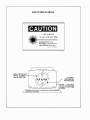
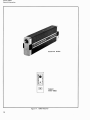
®
E stablished 1981
Advanced Test Equipment Rentals
www.atecorp.com 800-404-ATEC (2832)
Note
Title & Document Type:
Manual Part Number:
Serial Prefixes:
Revision Date:
10780A Laser Receiver for 5501A
10780-90006
1948A
March 1980
HP References in this Manual
This manual may contain references to HP or Hewlett-Packard. Please note that
Hewlett-Packard's former test and measurement, semiconductor products and
chemical analysis businesses are now part of Agilent Technologies.
Changes to this Manual
No changes have been made to this manual. All pages are scanned at 300 DPI
or greater.
About this Manual
This manual is reproduced from scans of an original document and images
OCR’d with Adobe Acrobat. OCR errors may exist and as such the user of this
document should take care and use common sense when referencing this
documentation.
Copyright Notice
This documentation is © Copyright 1980 Hewlett Packard and © Copyright 2006,
Jack Hudler, [email protected].
Permission to use and redistribute this documentation for non-commercial and
internal corporate purposes is hereby granted, free of charge.
Any redistribution of this documentation or its derivates must include this
copyright notice.
You may not sell this documentation or its derivations without written consent.
You may modify this documentation as necessary, but you may not sell
derivative works based on it.
You may include this documentation with the equipment/hardware on which it is
used for the purposes of selling the equipment/hardware. If you advertise that a
copy of this documentation is included in the sale, you must state that is for
“Free”.
Meaning if you want to gratuitously toss in a copy of the manual on an eBay sale,
it’s ok with me as long as you state it’s for free. No you can’t sell a digital archive
of manuals and say it includes a free copy of this documentation. You must give
it away with equipment.
I think you get the spirit of the copyright; it takes a lot of hours to scan and
replicate a manual. I just want this used in the spirit in which is it given.
Agilent if you have questions or wish to include this in your archive, please email
me.
.
OPERATING
AND
SERVICE
MANUAL
RECEIVER
(Part of 5501A Laser Transducer System)
SERIES 1948A
This manual applies directly to Hewlett-Packard Model 10780A
Receivers with Serial Prefix 1948A.
SERIES N U M B E R S NOT LISTED
For Serial Prefixes after 1 9 4 8 ~ a
, "Manual Change Sheet" i s
included with this manual. For Serial Prefixes below 1948A,
refer to Section 7, Manual Changes.
Copyright
HEWLETT- PACKARD COMPANY
1979
5301 STEVENS CREEK BLVD., SANTA CLARA, CALIF. 95050
Printed: MARCH 1980
MANUAL PART NO. 10780-90006
Microfiche No. 10780-90007
Printed in USA.
HEWLETT
PACKARD
CERTIFICATION
Hewlett-Packard Company certifies that this product met its published specifications at the time of shipment from the factory. Hewlett-Packard further certifies that its calibration measurements are traceable
to the Unitedstates National Bureau of Standards, to the extent allowed by the Bureau's calibration facility,
and to the calibration facilities of other international Standards Organization members.
WARRANTY
This Hewlett-Packardsystem product is warranted against defects in materials and workmanship for a period
of 90 days from date of installation. During the warranty period, HP will, at its option, either repair or replace
products which prove to be defective.
Warranty service of this product will be performed at Buyer's facility at no charge within HP service travel
areas. Outside HP service travel areas, warranty service will be performed at Buyer's facility only upon
HP's prior agreement and Buyer shall pay HP's round trip travel expenses. In all other cases, products
must be returned to a service facility designated by ii?.
For products returned to HP for warranty service, Buyer shall prepay shipping charges to HP and HP shall
pay shipping charges to return the product to Buyer. However, Buyer shall pay all shipping charges, duties,
and taxes for products returned to HP from another country.
HP warrants that its software and firmware designated by HP for use with an instrument will execute its
programming instructions when properly installed on that instrument. HP does not warrant that the operation of the instrument, or software, or firmware will be uninterrupted or error free.
LIMITATION O F WARRANTY
The foregoing warranty shall not apply to defects resulting from improper or inadequate maintenance
by Buyer, Buyer-supplied software or interfacing, unauthorized modification or misuse, operation outside
of the environmental specifications for the product, or improper site preparation or maintenance.
NO OTHER WARRANTY IS EXPRESSED OR IMPLIED. HP SPECIFICALLY DISCLAIMS
WARRANTIES OF MERCHANTABILITY AND FITNESS FOR A PARTICULAR PURPOSE.
THE IMPLIED
EXCLUSIVE REMEDIES
THE REMEDIES PROVIDED HEREIN ARE BUYER'S SOLE AND EXCLUSIVE REMEDIES. HP SHALL NOT
BE LIABLE FOR ANY DIRECT, INDIRECT, SPECIAL, INCIDENTAL, OR CONSEQUENTIAL DAMAGES,
WHETHER BASED O N CONTRACT, TORT, OR ANY OTHER LEGAL THEORY.
ASSISTANCE
Product maintenance agreements and other customer assistance agreements are available for HewlettPackard products.
For any assistance, contact your nearest Hewlett-Packard Sales and Service Office. Addresses are provided
at the back of this manual.
SAFETY PRECAUTIONS
LASER RADIATION
DO NOT STARE INTO BEAM
MAXIMUM OUTPUT: 1 mw
PULSE SPEC: continuous wave
LASER MEDIUM: helium neon
CLASS
XI
LASER PRODUCl
AVOID E X P O S U R E
BEAM CAN BE SHUT
OFF BY CLOSING
BLACK APERTURE
ALIGNMENT
APERTURE FOR
REDUCED BEAM
_I,
CAUTION - L a r r radlallon
when open and Interlock falled
ted. DO NOT STARE
INTO BEAM.
Thlr laser product conforms to Federal Bureau of Radlologlcal Health
Regulatlon8 21 CRF 1040.10.
\
Model 10780A
Contents
CONTENTS
......................................................
..........................................................................
................................................................
.........................................................................
SECTION 1 -- GENERAL INFORMATION
1-1
1.1 Introduction
1-1
1.3 Equipment Description
1-1
1.7 Identification
1-1
1.10 Specifications ........................................................................
1-1
.
.
.
.
SECTION 2 -- INSTALLATION AND OPERATION ............................................... 2-1
2.1 Introduction .......................................................................... 2-1
23
. . Unpacking and Inspecting
2-1
2.4 Storage and Shipment ................................................................. 2-1
2.8 Installation ........................................................................... 2-1
2.15 . Cabling ............................................................................. 2-2
2.17 . Operating Controls ..................................................................2-3
.
.
.
.............................................................
3-1
SECTION 3 -- THEORY OF OPERATION .......................................................
3-1
3.1 . Introduction ..........................................................................
33
. Circuit Description
3-1
.
....................................................................
SECTION 4
MAINTENANCE AND SERVICE .................................................. 4-1
4.1 . Introduction .......................................................................... 4-1
43
. . Maintenance ......................................................................... 4-1
46
. . Adjustments .......................................................................... 4-1
48
. . Troubleshooting ...................................................................... 4-2
--
SECTION 5 .
REPLACEABLE PARTS ........................................................... 5-1
5-1
5.1 Introduction ..........................................................................
5.3 Ordering Information
5-1
.
.
.................................................................
SECTION 6
MANUAL CHANGES ............................................................6-1
6.1 . Introduction ..........................................................................6-1
63
. . Manual Changes ...................................................................... 6-1
6.5 . Newer Instruments .................................................................6-1
67
. . Older Instruments ................................................................. 6-1
SECTION 7
SCHEMATIC DIAGRAM .........................................................7-1
7.1 . Introduction ..........................................................................7-1
--
--
FIGURES
Figure 1.1
Figure 2.1
Figure 7.1
Figure 7.2
.
10780A Receiver
.................................................................. 1-0
. Basic Measurement System ......................................................... 2-2
. Schematic Diagram Notes .......................................................... 7-2
. 10780A Doppler Receiver Schematic Diagram .......................................7-3
TABLES
Table 1.1 . 10780A Receiver Specifications ......................................................1-2
Table 2.1 . Model 10780A Receiver Signal Chart .................................................2-3
Table 5.1 Reference Designations and Abbreviations ...........................................5-2
Table 5.2 . Replaceable Parts ...................................................................5-3
Table 5.3 Manufacturers Code List ............................................................5-4
Table 6.1 . Backdating Changes ................................................................ 6-1
.
.
Model 10780A
General Information
1
1
TARGET
Model 10780A
General Information
SECTION 1
GENERAL INFORMATION
1-1. INTRODUCTION
1-2. This manual provides operation procedures, installation, theory, and maintenance information for the
10780A Receiver.
1-3. EQUIPMENT DESCRIPTION
1-4. The Model 10780A Receiver i s a photodetector/preamplifier module which senses the 5501A Laser
Head beam returning from an interferometer. The resultant radio frequency signal is the MEAS signal for
displacement measurement.
1-5. Since it is to be installed on the measurement axis of a machine, this small electronic module i s
lightweight, rugged, and easy to mount. It is highly resistive to electric noise and features a NEMA-12
enclosure. Designed to dissipate the least heat possible (less than 2.7 watts), it rests on plastic stand-off caps
so that convection currents may dissipate even this minimal energy. When nylon mounting screws are used
the Receiver is electrically isolated from the mounting points.
1-6. The photodiode is located on the 10780A Receiver in such a position that the module may be placed
above, below, left or right of the incoming laser beam. To aid in aligning the laser beam, a light-emitting
diode which lights when the beam is captured is conveniently located near the photodiode. A dcvoltage,
as a function of the incoming laser signal level, is also available for assistance in fine-tuning the laser beam
alignment. Initial receiver positioning, and coarse beam alignment is achieved with a snap-on beam target
fixture, which is supplied with the 10780A Receiver. The target is for beam alignment only. Remove this
fixture prior to operating the Receiver.
1-7. IDENTIFICATION
1-8. This manual is identified on the title page by equipment description and nomenclature, part number
and revision code, manual part number and publication date. Refer to information presented in the
following paragraphs and ensure that this manual applies to equipment being serviced.
1-9. Hewlet-Packard instruments have a two-section nine-digit plus one letter serial number usually
attached to the instrument rear panel. The four-digit prefix (first four digits from the left) identifies a group
of series of instruments manufactured identical to each other. The letter indicates the assembly plant
location. The five-digit serial number is different for each instrument. If the serial prefix of your
instruments differs from that listed on the title page of this manual, there are differences between this
manual and your instrument.
1-10. SPECIFICATIONS
1-11. Table 1-1 lists the characteristics and specifications for the 10780A Receiver.
Model 10780A
General Information
Table 7-7.
70780A Receiver Specifications
INPUT REQUIREMENTS
+I5 volts (+I)
at 0.18 amp maximum.
OUTPUT
Measurement Signal:
Differential square wave at Doppler-shifted frequency (100 kHz
to 5.0 MHz). Levels compatible with all Laser Transducer output
accessories.
Maximum cable length (using HP 10780-60003 Cable):
65 feet (20 meters)
ENCLOSURE
NEMA Type 12
M A X I M U M POWER DISSIPATION
2.7 watts (with 20 meter output cable)
WEIGHT
4.8 ounces (136 grams)
Model 10780A
Installation and Operation
SECTION 2
INSTALLATION A N D OPERATIO'
2-1. INTRODUCTION
2-2. This section contains information for unpacking, inspection, repacking, storage, and installation of the
10780A Receiver.
2-3. UNPACKING A N D INSPECTING
2-4. If the shipping carton is damaged, ask that the carrier's agent be present when the instrument is
unpacked. Inspect the instrument for damage. If the instrument is damaged or fails to meet electrical
specifications, notify the carrier and the ncare;: Ile-&lei-Packard Sales and Service office immediately
(offices are listed at the back of this manual). Retain the shipping carton and padding material for the
carrier's inspection. The Sales and Service office will arrange for the repair and replacement of your
instrument without waiting for the claim against the carrier to be settled.
2-5. STORAGE A N D SHIPMENT
2-6. To protect the Receiver during storage or shipment, good commercial packing methods should be
used. Reliable commercial packing and shipping companies have the facilities and materials to be
adequately repack an instrument.
NOTE
Before returning an instrument to Hewlett-Packard contact the nearest HewlettPackard Sales and Service office for instructions.
2-7. Conditions during storage and shipment should normally be limited as follows:
1. Maximum altitude: 25,000 feet.
2.
Minimum temperature: (-40' C).
3.
Maximum temperature: +167O F(+7S0 C).
2-8. INSTALLATION
2-9. The 10780A Receiver is shipped with the following items as standard equipment:
One (1)Alignment Target, 10780-40003.
One (1)Receiver Module, 10780A.
One (1)Interconnect Cable, 10780-60003.
Refer to the 5501A System Operating and Service Manual for cabling information.
Four (4) plastic machine screws (2 required).
Model 10780A
Installation and Operation
2-10. One 10780A Receiver package is required for each measurement axis in the Laser Transducer system
being installed. Figure 2-1 shows the required optic components, and the alignment of the receiver to
these optics, required for each measurement axis.
Figure 2-7. Basic Measurement System
2-11. Specific details for the placement of the receiver and its associated optics and installation examples
can be found in the Laser Transducer System Operating Manual. Also a detailed alignment procedure can
be found in the system operating manual.
2-12. Briefly, each axis of the Laser Transducer System has a receiver with a lens photodiode assembly in the
front. It must be positioned so that the polarizing vectors of the laser beam are parallel or perpendicular to
the line defined by the two mounting holes (within +3) as shown in Figure 2-1.
2-13. When mounting the receiver, the following points are important to remember:
At a 4!i0 position, the signal will go to zero.
The receiver dissipates between 2 and 2.7 watts. Plastic pads keep an air gap around the receiver and
also act as thermal and electrical isolators.
The cable to connect to the back connector of the receiver, must have ample room to make
connection. (See dimensional drawing Figure 2-28 in the 5501A System Operating and Service
Manual).
CAUTION
The receiver housing must be electrically isolated from the equipment that it i s to
be mounted on. Use nylon screws only.
2-14. CABLING
2-15. For cable preparation, connectors, and part numbers, refer to Appendix C of the 5501A System
Operating and Service Manual.
Model 10780A
Installation and Operation
2-16. OPERATING CONTROLS
2-17. There are no operating controls associated with the 10780A Receiver. However, there are operating
characteristics. An LED lamp lights to provide visual indication that the Receiver photo detector has
received an adequate laser beam. If, when the laser system is in operation, this LED does not light, perform
the alignment procedure in Section 2 of the Laser Transducer System Operating Manual. If this procedure
does not solve the problem, refer to the Checks and Adjustments section of this manual and the 5501A
System Operating and Service Manual for troubleshooting procedures. Refer to the Theory of Operation
section for more details on operational characteristics.
Table 2-7. Model 70780A Receiver Signal Chart
Input
Output
Signal Name
1
Function
I
source
Destination
Electrical signal corresponding to reflected Laser beam
frequency shift.
I/O Board
inverted verslon of MEAS
I/O Board
Fused +15V RET
Return path for +15V input
power.
I/O Board
Fused +15V
Receiver operating power
originating from the 5501A
Laser Transducer system, or
user designated power
source.
I/O Board
Model 10780A
Theory of Operation
SECTION 3
THEORY O F OPERATION
3-1. INTRODUCTION
3-2. This section provides a component-level discussion of the 10780A Receiver Circuit Operation.
3-3. CIRCUIT DESCRIPTION
3-4. The 10780A Receiver intercepts the doppler shifted difference measurement beam from the
Transducer Optical devices, and converts this beam into square wave MEAS (measurement)signals. These
signals are applied to an accessory unit and compared with REF (reference) signals (derived from the 5501A
Laser Head) to establish a displacement measurement value. In addition, the Receiver contains an LED
lamp which indicates adequate beam reception, and circuits that provide a monitoring voltage which
indicates relative intensity of the received beam.
3-5. The 5501A Laser Head or an external power supply source provides a +15 Vdc input to pin 4 of the
Receiver connector. This input is applied to Regulators U2 and U3 which produce nominal +5 Vdc and
+I0 Vdc operating voltages for the receiver.
3-6. The received beam illuminates a polarizing plate which is oriented to pass only 45 degree components
fo the f l (REF) and (f2 f Af) (MEAS) signals. CR1 mixes these two beam components and the resulting
amplitude modulated light generates an ac current at the difference frequency (i.e., f l - [f2 f Af]).
3-7. The CR2 difference frequency current is applied to R1, generating an ac voltage at the gate of Q1. A
high-to-low impedance circuit consisting of FET Q (source follower) and emmitter follower 4 2 matches
CR2 to high gain amplifier U1. Overload adjust potentiometer R12 is used to prevent overloading the highgain amplifier when the receiver is used in single axis systems.
3-8. The symptom of overloading is a decrease in the dc voltage at the beam monitor test point with an
increase in incident laser light. When overloading occurs, adjust R12 ccw until the overload condition is
corrected. (When rotating the control cw, the test voltage will begin to increase, then top out and then
begin to decrease. The proper setting for R12 is 0.2V before saturation.)
NOTE
R12 is provided primarily as an aid in alignment. Overloading does not affect the
laser system operation.
3-9. U1 provides a square wave output at a nominal amplitude of 2 volts (peak-to-peak). This signal is
applied to voltage amplifier 43. The resulting square wave output is applied to TTL Converter 44, which
provides a TTL level square wave input to Line Driver U5.The output from 4 3 is also applied to a detector
circuit consisting of CR1 and associated filter components. The resulting dc output level charges C8
proportionally to the input signal level. This dc level provides an external indication of received signal
strength (i.e., beam monitoring) and comprises one input to Threshold Detector U4.
3-10. Threshold adjust potentiometer R9 determines the triggering level of U4. This potentiometer is set so
that U4 changes state when the peak-to-peak signal level at TPI reaches approximately 15 millivolts. The
triggered Threshold Detector output goes to ground turning on LED diode indicator DSI. This indicates a
minimum beam strength of four microwatts or more has been received. The ground level signal also
enables Line Driver U5. U5 then responds to the TTL squarewave input signal from 4 4 by providing a
complementary squarewave output that comprises the transducer system MEAS and MEAS signals.
-
Model 10780A
Maintenance and Service
SECTION 4
MAINTENANCE A N D SERVICE
4-1. INTRODUCTION
4-2. This section contains maintenance and service information for the 10780A Receiver.
4-3. MAINTENANCE
4-4. To prevent problems, maintenance should be performed once every 6 months as follows:
--
VISUAL INSPECTION Inspect the unit for indication of mechqnical and electrical defects. Look for
signs of overheating, corrosion, accumulations of dust, oil, loose electrical connections, or broken
parts.
REPAIR AND CLEANING -- Repair any obvious defects; and if necessary, clean the unit with a brush,
compressed clean dry air jet, or a vacuum cleaner, or a suitable liquid solvent.
4-5. Periodically you may also wish to verify proper beam alignment. For this procedure, refer to the Laser
Transducer System Operating Manual.
4-6. ADJUSTMENTS
4-7. The following procedure sets the 10780A Receiver adjustments. Initially, the adjustments are made
with the receiver located in line from the furthest beam splitter, then the system is setup in the desired user
configuration and checked.
1. Align the system on the machine in the desired configuration using the maximum number of
optical beam splitters.
2.
Remove the Receiver cover to gain access to the adjustment potentiometers.
3.
Connect an oscilloscope to the Beam Monitor test point on the back of the Receiver.
4.
Place Receiver in the beam path in line from the furthest optical beam splitter where the signal
strength should be minimum.
BEAM
SPLITTERS
=-T'+P-=
LASER HEAD
5. Position Receiver for maximum signal indication on oscillosco)~e.Maximum signal should be about
1 volt.
6. Adjust R12 overload potentiometer fully ccw, then rotate cw until saturation is reached i.e., point
where a further cw adjustment results in very little voltage increase. From the saturation point,
adjust R12 ccw until the voltage at the beam monitor test point decreases by 0.2V.
Model 10780A
Maintenance and Service
7.
Reposition the receiver for maximum signal at the beam monitor test point.
8.
Check that the receiver is not saturated by repeating step 6 and noting if adjustment point i s the
same. Repeat steps 6 ard 7 as necessary to maximize the beam monitor test point voltage at 0.2V
short of saturation.
9.
Place the receiver and optics in the configuration to be used and position the receiver for
maximum beam monitor test point voltage.
NOTE
Record the voltage reading at the beam monitor test point for use as an axis
reference for future troubleshooting.
10.
Break the measurement beam and ch,eck the beam indicator LED on the 10780A. If on, adjust R9
threshold adjust until LED just goes out.
4-8. TROUBLESHOOTING
4-9. Use the schematic diagram Figure 4-2 for troubleshooting. The schematic shows test points, voltages,
and waveforms for the various stages of the receiver.
Model 10780A
Replaceable Parts
SECTION 5
REPLACEABLE PARTS
5-1. INTRODUCTION
5-2. This section contains a listing of replaceable parts for the 10780A Receiver (Table 5-2), a list of
manufacturers codes (Table 5-3), an explanation of the reference designations and abbreviations used in
the replaceable parts list (Table 5-1) and information on how to order replaceable parts.
5-3. ORDERING INFORMATION
5-4. To obtain replacement parts, address your order to your local Hewlett-Packard Sales and Service
Office listed at the back of this manual. Identify parts by their Hewlett-Packardpart number (seeTable 5-2).
To obtain a part that is not listed or does not show an associated part number, provide the following
information when ordering:
Instrument model number.
Instrument serial number.
Description of the part.
Function and location of the part as near as you can determine them.
An explanation of instrument model numbers and instrument serial numbers can be found in the Laser
Head Operating and Service Manual.
M o d e l 10780A
Replaceable Parts
Table 5-7. Reference Designations and Abbreviations
REFERENCE DESIGNATIONS
A
AT
B
BT
C
CP
CR
DC
= assembly
= attenuator sola at or
termlnatlon
= fan. motor
= battery
= capacttor
= coupler
= dbode diode thyristor
varactor
= dtrecttonal coupler
DL
DS
E
F
FL
H
HY
J
= delay line
= annunciator: signaling device
.aud~bleor visual': lamo: LED
= mlscellaneouselectr~calpart
=fuse
= fllter
= hardware
= carculator
= electr~calconnector statlonary
portlon lack
K
L.
M
MP
P
I2
R
RT
S
,
= relay
= co~l,~nductor
= metre
= miscellaneous mechantcal part
= electrical connector movable
portlon plug
= translstor SCR lrlode thyrlslcr
= resostor
= thermtstor
= switch
= transformer
= termtnal board
= thermocouple
=test polnl
= Integrated clrcult. mtcroclrcult
= electron tube
= voltage regulator. breakdown dlode
= cable, transmlsslon path, wlre
= socket
= crystal unll-pmzoeleclrlc
= tuned cavlly tuned clrcult
T
TB
TC
TP
U
V
VR
W
x
Y
Z
1
ABBREVIATIONS
ampere
allernatlng current
accessory
adlustment
analog-lod~gltal
audlo frequency
= automatic frequency Control
automat#cgaln control
= alumdnum
= aulomaltc level Control
= amplllude modulallon
= ampllfler
=automat~cphasecontrol
= assembly
= aux~liary
= average
= amertcan mre gauge
= balance
= blnary ccded declmal
= board
= beryllium copper
= beat frequency osclllator
= b~nderhead
= breakdown
= bandpass
= bandpass fllter
= brass
= backward-wave osclllator
= cal~brate
= counlerclockwIse
= ceramlc
= channel
= cenl~meter
= coaxla1
= coeff!ctent
= common
= iompoSlt1on
= complete
= connector
= cadmtum plate
= cathode-ray tube
= complementary translstor 11391C
= contanuous wave
= ClockwISe
CW
= dlgltal-to-analog
DIA
= declbel
dB
=dec!bel relerred to 1mW
dBm
= dtrect current
dC
= degree temperature
deg
~ntervalor d~lference
0
= degree plane angle
= degreeCelslus centr~grade
"C
= degree Fahrenheit
"F
= degree Kelvln
'K
= deposlled carbon
DEPC
= detector
DET
= d~ameter
dlam
= dlameler used In parts list
DIA
DlFF AM1PL= d~fferentlatampllller
= d~v$s~on
dlV
= double-pole. double-throw
DPDT
= drive
DR
= double stdeband
DSB
= d~odetranslstor loglc
DTL
= dbgltal voltmeter
DVM
= em~tlercoupled logtc
ECL
= electromotive force
EMF
= electrontc data processing
EDP
= electrolyllc
ELECT
= encapsulated
ENCAP
:
external
EXT
F
= farad
= fleld-effect translstor
FET
FlF
= flip-flop
FH
= flat head
= foll~sterhead
FOL n
= frequency mcdulatlon
FM
= front panel
FP
:
frequency
FREO
= fkxed
FXD
= gram
9
= germanbum
GE
= glgahenz
GHz
= glass
GL
= ground ed
GND
= henry
H
= hour
h
= heterodyne
HET
= hexagonal
HEX
ac
ACCESS
ADJ
AID
AF
AFC
AGC
AL
ALC
AM
AMPL
APC
ASSY
AUX
AVG
AWG
BAL
BCD
ED
BE CU
BFO
BH
BKDN
BP
BPF
BRS
BWO
CAL
ccw
CER
CHAN
cm
CMO
COEF
COM
COMP
COMPL
CONN
CP
CRT
CTL
CW
...
=
=
=
=
=
=
-
HD
HMN
HF
HG
HI
HP
HPF
HR
HV
Hz
= head
=hardware
= hlgh frequency
= mercury
= htgh
= Hewlett-Packard
= htgh pass f~ller
hour used #nparts list
= h ~ g hvoltage
=hertz
= ~ntegraledc~rcult
= lnslde doameter
= tntermed~atefrequency
= ~mpregnated
= lnch
= incandescent
= Include s
= lnput
= ~nsulat~on
= ~nlernal
= kologram
= kolohertz
= kllohm
= k~lovolt
= pound
-
NE
NEG
nF
Nl PL
NIO
NOM
NORM
NPN
NPO
= nwn
= negatlve
= nanofarad
= nlckel plate
= normally open
= nofnlnal
= normal
=
negative-pos$t#w-negallw
= negatlvep~ltlvezero zero
temperature coeff~ctent
NRFR
= not recommended for fleld
IC
replacement
ID
IF
ns
= nanosecond
IMPG
NSR
= not separately replaceable
nW
= nanowan
INCD
OBD
= order by descnptton
OD
= outslde dlameter
INCL
OH
INP
= oval head
OP AMPL = Operal~onalampllfser
INS
OPT
INT
= optton
OSC
= osc~llator
k9
ox
= oxlde
kHz
= ounce
OZ
kll
=ohm
I1
kV
P
Ib
= peak fused In parts Itst,
PAM
=
tnductance-capacitance
=
pulse-amplitude mcdulatlon
LC
= light-emtttlng &ode
= prlnted clrcult
PC
LED
LF
= low frequency
= pulse-code modulat~on.
PCM
= long
LG
pulse-count mcdulat~on
= k f t hand
PDM
LH
= pulseduratlon modulatlon
= llmlt
LIM
= picofarad
PF
= ltnear taper used In parts llsl
LIN
PH BRZ
= phosphor bronze
Ion
= Itnear
PHL
= phtlltps
PIN
LK WASH = lockwasher
= ~ostt~ve-~nlnns~c-n~(lat~m
PIV
= tow local oscillator
= peak Inverse volts&
LO
= loqar~thm~c
taper used
=peak
LOG
Pk
PL
= phase lock
In parts l ~ s t
PLO
=
logarithm
IC
= phase lock osclllalor
'09
PM
= low pass f~lter
=phase modulatfon
LPF
PNP
LV
= low voltage
= p0~111venegall~e-p0~lttve
m
PI0
= part of
= metre dlstance
= mlll~ampere
mA
POLY
= Polystyrene
MAX
= maximum
= porcelain
PORC
= megohm
POS
= posltlve posltlon s used In
= meg 106 used ~nparts lhst
MEG
parts llst
POSN
MET FLM = metal lllm
= POSltlO"
MET OX = metal oxlde
POT
= potentlometer
= med~umfrequency. m~crofarad P-P
= peak-to-peak
PP
used In parts l ~ s t
= peak-to-peak used In parts ltst
MFR
= manufacturer
PPM
= pulse-POSIIIO~
modulatlon
= m~lllgram
PREAMPL = preampllfler
mg
PRF
. . ..
MHz
= megahertz
= pulse-repetltlon frequency
mH
= mlllthenry
PRR
= pulse repetltlon rate
mho
= conductance
= pocosecond
MIN
= mlndmum
= point
mln
= mlnute tlme
PTM
= pulse-lame modulatton
= mnnute plane angle
PWM
= pulse-wldth modulat~on
PWV
MlNAT
= mlntature
= peak workang voltage
mm
= mtlllmetre
= resistance CaDaColanCe
MOD
= modulator
RECT
= rectrleer
= momentaw
MOM
REF
= reference
= metal-oxlde semlconductor
= regulated
MOS
REG
= m~ll~second
ms
REPL
= replaceable
RF
= mountlng
MTG
= radto frequency
MTR
RFI
= meter ~ndlcattngdevlce
= radlo frequency ~nterference
mV
= mllllvolt
RH
= round head. r~ghthand
= mllllvolt aC
mVac
= resistance-inductance-capacllatlce
RLC
= mtlllvolt dc '
mVdc
= rack mount only
RMO
mVpk
= millivolt peak
rms
= root-mean-square
peak-to-peak
RND
= round
~ V P - P = m~ll~volt.
ROM
= m~ll~volt
rms
mVrms
= read-only memory
= m~llvwatt
RIP
mW
= rack and Danel
RWV
= reverse worklng voltage
MUX
= multtplex
MY
S
= mylar
= scatlerlng parameter
= mtcroampere
= second ttme
rA
= mlcrofarad
= second plane angle
UF
= m~crohenry
S-B
= slow-blow fuse used In parts 1st
rH
= mlcromho
~mho
SCR
= slllcon controlled recttfler, screw
= microsecond
= selenium
SE
us
= mlcrovolt
SECT
= sectlons
PV
#Vat
= mlcrovolt, ac
SEMICON = semlconductor
uVdc
= mlcrovolt. dc
SHF
= superhlgh frequency
= mlcrovolt. peak
SI
= stllcon
rvpk
= m~crovolt.peak-to-peak
SIL
= stlver
uVP-P
= mlcrovoll. rms
rVrms
SL
= s11de
= mlcrowatt
SNR
= srgnal-to-noise ratlo
rW
nA
= nanoampere
SPDT
= songle-pole. double-throw
NC
= no connection
SPG
= sprtng
= normally closed
N/C
SR
= spill ring
...
SPST
SSB
SST
STL
sa
SWR
SYNC
T
TA
TC
TD
TERM
TFT
TGL
THD
THRU
TI
TOL
TSTR
TT L
TV
N I
TWT
U
UF
UHF
UNREG
vac
V AR
VCO
VdC
VDCW
V,F,
VFO
VHF
VDk
VP-P
Vrms
VSWR
VTO
WVM
vX
W
W/
WIV
WW
W/O
YIG
zo
= angle-pole. s~ngle-throw
= slngle s~deband
= sta1nloss steel
= steel
= square
= standtng-wave ratto
= Synchronize
= tlmed slow-blow fuse
= tantalum
= temperature compensating
= Idme delay
= termlnal
= thtn-fllm transstor
= toggle
-- thread
= through
= tttanlurn
= tolerance
= trimmer
= lrans~slor
= transistor-transistor loglc
= televtslon
= televtslon lnterlerence
= travel~ngwave tube
= mlcro ,10-6, used In parts l ~ s t
= m~crofarad used In parts IISII
= Ultrahtgh frequency
= unregulated
= volt
= vcltampere
= volts ac
= vanable
parts llst
= volts filtered
= vanable-frequency osclllator
= very-hlgh frequency
= volts peak
= volts peak-to-peak
= volts rms
= voltage standlng wave ratlo
= voltage-tuned osclllator
= vacuum-tube voltmeter
= volts swntched
= watt
= with
= worklng Inverse voltage
= wlrewound
= w~lhout
= yttrtum-won-garnet
= charactertstic ~mpedance
..
...
..."
NOTE
All abbreviat~onsin the parts Itst w ~ l l
be in upper case.
MULTIPLIERS
T
G
M
k
da
d
c
m
n
P
1
a
tera
gtga
mega
kt10
deka
decl
centi
mill!
rndcro
nano
poco
femlo
ano
1012
109
106
103
10
10-1
10-2
10-3
10-6
10-9
10-12
10-15
to-$8
Model 10780A
Replaceable Parts
Table 5-2. Replaceable Parts
Mfr
Code
HPPart
Number
c
D
Qw
10780-b0101
8
1
DOPPLER RECEIVER
BOARD I~SLMBLY
(SERIE8 1 6 0 0 1 )
28080
10780-60101
C1
0180-0230
9
1
CAPACITOR-FXD lUF+-20% SOVDC TA
7
9
7
1
S
1
CAPACITOR-1x0
CAPACITOR-CXO
CAPACITOR-CXO
CAPACITOR-?ID
.IUC
*-a01 sovoc CER
lOP* *-5% SOOVOC MICA
.OlUC * - 2 0 1 5OVDC CCR
33UC*-10% lOVDC T I
Sb289
28080
28080
18080
36289
lSOD105X0050A2
OI~O-0080
0160-0205
01bO-3277
0180-0120
a
C3
CQ
C5
Olb0-3277
0180-0230
0160-0080
OlbO-2327
01bO-3277
9
0
8
8
9
CAPACITOR-CXD
CAPACITOR-IXO
CAPACITOR-CXD
CAPACITOR-CXD
CAPACITOR-CXD
.OLUC +-20% SOVOC CER
lUC*-20% SOVDC T I
.IUf *-20% SOVDC CCR
IOOOCC *-20% lOOVOC CER
. O l U I *-20% SOVDC CER
28080
56289
28480
28480
28080
0160-3277
lSOOlOSXOO5OA2
0160-4084
Olb0-2327
01bO-3277
b
9
9
0
0
ZZUI+-~OX
CRl
0180-0228
OlbO-3277
01bO-3277
Olb0-0137
OlbO-0137
0160-0576
1901-0179
7
I
~ S V O CT A
. O I U I + - 2 0 1 SOVDC CER
.OlUC +-20% SOVDC CER
.33UC +-20% 25VOC CER
.33UC +-20% ZSVOC CCR
CAPACITOR-FXD 0 1 UF+-20% 50 VDC CER
DlODC-SWllCUINC ISV SOMA 7SOPS DO-?
2
8
28480
28480
28480
28480
28480
28480
150022bX90lSB2
0160-1277
0160-3277
OlbO-0137
0160-0137
0160-0576
1901-0179
0.91
1090-0522
I
I
LCD-VISI8LE L U M - I N T w ~ ~ M C D
ICwSOMA-MIX
28480
5082-408
Ql
QL
1
2
7
3
I
QU
1855-0081
1854-0092
1853-0015
1854-0019
TRAN8ISTOR
TRANSISTOR
TRANSISTOR
TRANSISTOR
01ZVS
28080
28080
28480
2NS205
1814-0092
1853-0015
18SQ-0019
91
12
R3
R4
P5
0757-0959
0757-0908
0757~0930
0757-0908
0757-0964
3
0
0
0
0
1
3
1
ZOSOb
20SOb
24501
2054b
ZOSQ~
C1-1~8-~0-3002-G
CO-148-10-1002-6
C4-148-TO-2701-G
C4-118-TO-1002-6
~~-1/8-T0-070~-~
Rb
R7
R8
a9
I10
0757-0913
0737-0811
0751-0948
2100-2030
3
7
0
b
1
I
S
O
20506
ZO5Ub
73138
C1-148-TO-2001-6
CO-148-TO-301-C
CO-l/8-lO-1002-6
8ZCRZOK
1 11
a12
R13
R10
RlS
CtOO-2522
0757-0960
0757-0919
I
I
0
S
I
NOT AS816NEO
nE81STOR-TRYR 10K 1OX C 8IDE-AOJ I-TRN
RESISTOR O7K CX ,125N ITCWO+-100
RESISTOR 6 2 0 ZX ,125W C TC80*-100
NOT I8SICNED
30983
24SOb
20506
El5OXlO3
CO-148-TO-0702-G
CO-148-TO-621-C
RIb
R17
1118
R19
R20
0757-0961
0683-1815
0757-0926
0757-0950
0757-OQSb
7
S
4
8
b
1
RESISTOR
RESISTOR
RESl8TOR
RESISTOR
RCIISTOR
3bK 2% .12SW ITCW0+-100
1 8 0 5 % .2SM CC TC8-00O/+bOO
1.2K ZX ,125W ITCWO+-100
18K ZX ,125W C TCWO+-100
3.3K ZX ,125W ITCWO+-100
a0506
01121
24506
20506
24546
CO-148-TO-JbO2-6
C8181s
CO-148-TO-1201-c
CO-148-10-1802-6
C0-148*T0-3101-G
R21
R22
123
a24
R2S
0757-0898
0751-0923
0757-0930
0757-0923
0757-0909
9
1
0
3
3
I
1
1
1
RESISTOR
RESISTOR
RESISTOR
RESISTOR
RCSISTOR
8 2 ZX ,125W C TCwO*-100
910 ZX ,125W ITC.O*-100
1.8K 2% .12SW ITCWO*-LOO
1.1K 2% ,125M ITC.O+-LOO
200 2 % ,125W ITC.01-100
24S4b
20346
245Ub
Z454b
ZOS4b
CO-148-10-82R0-6
CO-118-TO-911-6
CO-148-10-1801-6
CO-148-TO-1101-6
C4-148-10-241-6
R2b
0737-0900
4
1
RESISTOR 1 0 0 2 % ,125W
2U54b
CO-148-TO-101-G
U1
U2
U1
U4
US
1826-0037
182b-0121
182b-0390
182b-0015
1810-0720
b
0
I
0
2
I
IC
IC
IC
IC
RC/IC AMPL 10-99
7 8 0 5 V ROLTR 10-220
V RGLTR 10-19
311 COMPARATOR 8-DIP-P
IC
DRVR TTL LEO ORVR DUAL 1-1NP
00711
07261
Z7OlU
01295
27014
MC159OC
78OSUC
LM78LIOACH
SNTaJllC
08883ON
~2
10780-boo02
8
1
DCTECTOR ISSLMBLY
(REPLACEABLE ONLY A8 AN I S 8 L M I L Y )
28080
10780-6000~
Reference
Designation
'I
cz
C0
C7
C8
C8
ClO
Ctl
C12
C I3
Clu
C 15
C16
03
8
z
1
I
I
2
I
I
I
2
I
1
I
I
I
I
1
1
1
Description
CAPACITOR-~XD
CAPACITOR-CXO
CAPACITOR-CXO
CIPACITOR-CXD
CAPACITOR-CXO
RtSI8TOR
RCSISTOR
RESISTOR
RC818TOR
RESISTOR
J-VET N-CHIN 0-MODE 8 1
NPN 8 1 PDw2OOMW ITWbOOMUZ
PNP 8 1 POwZOOMN CTwSOOMYZ
NPN 8 1 10-18 POw3bOMW
101
101
2.7K
101
471
2 % ,125W
2X ,125N
ZX .I25W
2 % .lZSW
2% ,125W
R t S l S l O R 2.11 2% ,125W
RCSISTOR 1 0 0 ZX .125W
RcSISTOR !OK 2% .12SW
RC8ISTOR-TRMR 2 0 1 10%
NOT A8SIGNED
C T~.0+-100
C TC.O*-100
C TC801-100
C TCwO*-100
ITCWO*-LOO
C TCwO+-100
ITCwO*-100
IT C ~ 0 * - 1 0 0
C TOP-ADJ 1-TRN
IlCWO+-100
Mfr Part Number
0160-008a
0 1 60-0205
01bO-3277
150033bX9010B2
C3
OlbO-2009
1
1
CAPACITOR-IDTYRU S000PC +8O - 2 0 1 SOOV
28080
0160-2009
JI
1251-3051
1251-3052
5
b
1
1
CONNECTOR 0 - P I N
CONNECTOR 0-PIN
28080
zt080
1aS1-5051
1251-3052
10780-20000
10780-20005
10780-20001
10780-00002
10780-20002
b
7
8
2
4
I
CAP, FRONT
CAP, REAR
COVER, BOTTOM
YEAT SINK
SPACER
28080
28080
28080
28080
28480
10780-20001
10780-10005
10180-10006
10780-00002
10780-20002
10780-00002
10780-00003
0300-0010
b
7
8
0
SPACER
TARGElr ALIGNMENT
INSULATOR-XSTR NYLON
28080
28480
28480
10780-40002
10780-00003
0300-0410
2360-03b0
1078040003
0
4
8CREW-MACH b - 1 2
1
CABLE 2U METERS 165 FTI
00000
28480
ORDER 8Y OL8CRIPTION
1078060003
CIRCULAR
CIRCULAR
MI8CELLINEOU8 PIRTS
1
I
1
I
I
2
1-IN-LG
CAN-YO-SLT
See introduction to t h i s s e c t i o n for ordering information
*Indicates factory selected value
Model 10780A
Replaceable Parts
Table 5-3. Manufacturers Code List
Mfr. No.
00000
01121
01295
04713
07263
24546
27014
28480
30983
56289
73138
Manufacturer Name
Any Satisfactory Supplier
Allen-Bradley Co.
Texas Instruments, Inc., Semiconductor Cmpnt. Div.
Motorola Semiconductor Products
Fairchild Semiconductor Division
Corning Class Works (Bradford)
National Semiconductor Corp.
Hewlett-Packard Co., Corporate Headquarters
Mepco/Electra Corp.
Sprague Electric Co.
Beckman Instruments, Inc., Helipot Division
Address
Milwaukee, WI
Dallas, TX
Phoenix, AZ
Mountain View, CA
Bradford, PA
Santa Clara, CA
Palo Alto, CA
San Diego, CA
North Adams, M A
Fullerton, CA
ZIP Code
53204
75222
85062
94042
16701
95051
94304
92121
01247
92634
Model 10780A
Manual Changes
SECTION 6
MANUAL CHANGES
6-1. INTRODUCTION
6-2. This section of the manual contains information necessary to update the manual to cover newer
instruments and to backdate the manual to cover older instruments.
6-3. MANUAL CHANGES
6-4. This manual applies directly to units having serial number prefix 1948A. For units with different serial
number prefixes, refer to the following paragraphs.
6-5. NEWER INSTRUMENTS
6-6. New instruments may have higher serial number prefixes that are listed on the title page of this
manual. The manuals shipped with these units will include a "Manual Changes" sheet that describes all
required manual changes. If the updating information is missing, contact the local HP Sales and Service
Office for information.
6-7. OLDER INSTRUMENTS
6-8. Table 6-1 lists the serial numbers and serial number prefixes of units that differ electrically from the
units documented in this manual. Find the prefix or range of serial numbers that corresponds to your unit,
and make the manual changes specified in Table 6-1.
Table 6-1. Backdating Changes
Serial Number
or Prefix
Make These Manual Changes
1912A
1
1644A
12
1504A
1,2,3
1408A
1,2,3,4
CHANCE ?
For units with serial prefix 1912A and below, the 10780-60003cable was not supplied. Instead a 4-pin connector P/N 1251-3452 was supplied to wire an interconnecting cable between the receiver and the Laser
System electronics.
Page 2-1, Paragraph 2-9, Item 3:
Delete the sentence and replace with "One (1)4-pin connector, P/N 1251-3452, that may need to be
wired to an interconnecting cable which connects the receiver to the Laser System electronics.
Page 2-1, Add the following paragraph:
"2-9a. In addition, an interconnecting cable is required to con,bect the receiver to the Laser System
electronics. This cable is specified when ordering the Laser System."
Page 1-2, Table 1-1:
In the Maximum Cable Length specification, replace "10780-60003" with "C05-59995A". This was the
special order available with the 10780A.
Model 10780A
Manual Changes
Page 5-3, Table 5-2, Replacement Parts:
Delete the 10780-60003 cable and the listing.
CHANGE 2
Page 5-3, Table 5-2, Replaceable Parts:
Delete AlC16 and listing.
Page 7-3, Figure 7-2, Schematic Diagram:
O n component, delete C16. O n schematic, delete C16.01. Add jumper W1 between the +10 volt line
and U1 pin 6. Add jumper W2 between ground and U3 pin 3.
CHANGE 3
Page 5-3, Table 5-2 Replaceable Parts:
Add R10/0757-0919/1/R:FXD FLM 620 O H M 2% lhW/28480/0757-0919.
Add R11/0757-0912/1/R: FXD MET FLM 330 O H M 2% lhW/28480/0757-0912.
Change the value of R17 from 180 O H M 1/4W t o 130 O H M l/'W.
Change HP Part Number of U3 from 1826-0384 to 1820-0429 and Mfg. Number t o LM309H.
Delete W2.
Page 7-3, Figure 7-2 Schematic Diagram:
Delete W2 jumper wire from U3(3) t o ground.
Add R10 (620 OHM) and R11 (330 OHM) from U3(2,3) to ground as shown below:
FROM J l ( 4 ) . U2(11
-
1
U3
2
RlO
3
tC9
tCi1
-
-
b t10V
t
R11
330
Change value of R17 from 180 O H M to 130 OHM.
O n Integrated Circuit Chart, change U3 HP Part No. from 1826-0394 t o 1820-0429 and Mfg. No. from
78L10 ACH to LM309H.
CHANGE 4
Page 5-3, Table 5-2 Replaceable Parts:
Change R14 from 620 O H M (HP Part No. 0575-0919) to read:
R14/0757-9021/1/R: FXD MET FLM 750 O H M 2% lhW/28480/0757-0921.
Delete W1 (HP Part No. 8155-0005).
Add R15/1/0757-0921/R: FXD MET FLM 750 O H M 2% 1/8W/28480/0757-0921.
Page 7-3, Figure 7-2 Schematic Diagram:
Change the value of R14 from 620 to 750.
Delete W1 and replace with R15 (750 OHM). R15 connects from Ul(6) t o +10V.
Model 10780A
Schematic Diagrams
SECTION 7
SCHEMATIC DIAGRAM
7-1. INTRODUCTION
7-2. This section of the manual contains a schematic diagram of the 10780A Receiver circuit board assembly
and additional supportive information as listed below.
Schematic diagram notes, Figure 7-1, which describes symbols and reference designations of
components and assemblies used in the Receiver.
Component locator and an integrated circuit chart for the 10780A Receiver board.
7-3. Use the information in this section in conjunction with the information provided in Section IV for
maintenance and servicing.
Model 10780A
Schematic Diagrams
r
f
n
SYMBOLS
FRONT P A N E L
0
REAR P A N E L
L--J
(-)
-
MAIN SIGNAL P A T H
FEEDBACK P A T H
TEST POINT
INTERIOR AND P C BOARDS
a
&
+
"ANDe* G A T E
WIPER MOVES TOWARD "CW" WHEN
CONTROL IS R O T A T E D CLOCKWISE
"OR"
POWER L I N E GROUND
€-
CIRCUIT COMMON GROUND
Q
F L O A T I N G GROUND
rh
CHASSIS GROUND
0
KNOB CONTROL
0
SCREWDRIVER ADJUST
GATE
INVERTER
NAND G A T E
NOR G A T E
EXCLUSIVE NOR
PRINTED CIRCUIT BOARD IDENTIFICATION
REVISION LETTER
HP PART NO.
05340-60037
-2318
DIVISION CODE
PRODUCTION CODE
SERIES NO.
(May Be Stamped
Elsewhere On The Board)
REFERENCE DESIGNATIONS
REFERENCE DESIGNATIONS WITHIN ASSEMBLIES ARE ABBREVIATED. ADD ASSEMBLY NUMBER TO ABBREVIATION FOR COMPLETE DESCRIPTION. JACKS ARE THE STATIONARY CONNECTORS
AND PLUGS ARE THE MORE MOVEABLE OF TWO CONNECTORS.
ASSEMBLY
ABBREVIATION
COMPLETE DESCRIPTION
A25
A25A1
NO PREFIX
C1
CR1
53
A 2 X1
A25AlCR1
53
Assembly
Number
A
Assembly Stk. No. Assembly Serles No.
(meludes A25Al
fused lo document
Assembly)
changes)
Assembly
Name
-
A
d
A25-POWER SUPPLY AssY(05100-60071
-
SERIES 330
52 mounted on
Assembly A25
Numbers mdrcate
I
Rectrfter ,-A1
Assembly
Port of A25
RECTIFIER ASSY
7
1
53 not mounted
Assembly A25
+6 3 V
TO
A5P1(6)
\
6.3V supplied
from 53 to Pin 6
Termr~l
Numbers
I
,
of PI on
Connector A25XAl
Numbers
hsembly A5
I
I
Figure 7-7.Schematic Diagram Notes
HEAT SINK
f- --- --
I
I
i
i
AI
A l RECEIVER BOARD A S S EMBLY
( I0780
- 60101)- -SERIES
1644A
I
-
-
-
-- 1
NOTES
10780A RECEIVER INTEGRATED CIRCUIT CHART
-
THRESHOLD
ADJ (SEE ADJUSTMENT PROCEDURE, SECTION 4
7 REGULATOR 7
P/O J I
FUSED
15V 4
I
U2
2
<;
-
* +5v
I
FUSED
RETURN
vcc
GND
Pin 7(+10V)
Pins 4. 8
As shown
on schematic
As shown
on schematic
As shown
on schematic
As shown
on scllematic
As shown
on schematic
As shown
on schematic
Pin 14(+5V)
Pin 7
PART NUMBER
HP
VENDOR
3
I
15V
REFERENCE
DESIGNATION
i
3
<
$
7
4
REGULATOR 7
,,
I
I
+
-
I -
Cl
I .OUF
U3
2
f.~:-f
+
3
CI I
22UF
c +IOV
v
F i g u r e 7-2
10780A Doppler Receiver Schematic Diagram
HEWLETT
PACKARD
MANUAL PART NO. 10780-90006
PRINTED I N U.S.A.