1
®
E stablished 1981
Advanced Test Equipment Rentals
www.atecorp.com 800-404-ATEC (2832)
GS820
Multi Channel Source Measure Unit
IM 765601-01E
2nd Edition
Thank you for purchasing the GS820 Multi Channel Source Measure Unit.
This user’s manual contains useful information about the instrument’s functions and
operating procedures and lists the handling precautions of the GS820. To ensure correct
use, please read this manual thoroughly before beginning operation. Keep this manual in
a safe place for quick reference in the event a question arises.
Manual Title
Manual No.
Description
GS820 Multi Channel Source IM 765601-01E This manual. Explains all the functions of the
Measure Unit User’s Manual
GS820 and their operating procedures.
Notes
Trademarks
Revisions
• The contents of this manual are subject to change without prior notice as a result of
continuing improvements to the instrument’s performance and functions. The figures
given in this manual may differ from those that actually appear on your screen.
• Every effort has been made in the preparation of this manual to ensure the accuracy
of its contents. However, should you have any questions or find any errors, please
contact your nearest YOKOGAWA dealer.
• Copying or reproducing all or any part of the contents of this manual without
YOKOGAWA’s permission is strictly prohibited.
• The TCP/IP software of this product and the document concerning the TCP/IP
software have been developed/created by YOKOGAWA based on the BSD Networking
Software, Release 1 that has been licensed from University of California.
• Microsoft, Internet Explorer, MS-DOS, Windows, Windows NT, and Windows XP are
either registered trademarks or trademarks of Microsoft Corporation in the United
States and/or other countries.
• Adobe, Acrobat, and PostScript are trademarks of Adobe Systems Incorporated.
• For purposes of this manual, the TM and ® symbols do not accompany their
respective trademark names or registered trademark names.
• Other company and product names are registered trademarks or trademarks of their
respective holders.
• 1st Edition:August 2007
• 2nd Edition: July 2012
2nd Edition : July 2012 (YMI)
All Rights Reserved, Copyright © 2007 Yokogawa Electric Corporation
All Rights Reserved, Copyright © 2012 Yokogawa Meters & Instruments Corporation
IM 765601-01E
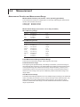
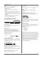
Checking the Contents of the Package
Unpack the box and check the contents before operating the instrument. If some of the
contents are not correct or missing or if there is physical damage, contact the dealer from
which you purchased them.
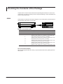
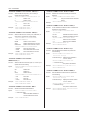
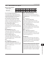
GS820
Check that the model name and suffix code given on the name plate on the side panel of
the instrument match those on your order.
MODEL
SUFFIX
MODEL
SUFFIX
NO.
Made in Japan
NO.
Made in Japan
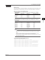
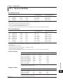
MODEL and SUFFIX Codes
Model
Suffix Code
Description
765601
Standard model (external I/O connector: 15 pins)
765602
Digital I/O model (external I/O connector: 50 pins)
Power cord -D -F -Q -R -H UL/CSA Standard Power Cord (Part No.: A1006WD)
[Maximum rated voltage: 125 V; Maximum rated current: 7A]
VDE Standard Power Cord (Part No.: A1009WD)
[Maximum rated voltage: 250 V; Maximum rated current: 10 A]
BS Standard Power Cord (Part No.: A1054WD)
[Maximum rated voltage: 250 V; Maximum rated current: 10 A]
AS Standard Power Cord (Part No.: A1024WD)
[Maximum rated voltage: 250 V; Maximum rated current: 10 A]
GB Standard Power Cord (Part No.: A1064WD)
[Maximum rated voltage: 250 V; Maximum rated current: 10 A]
NO. (Instrument Number)
When contacting the dealer from which you purchased the instrument, please give them
this number.
ii
IM 765601-01E
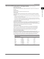
Checking the Contents of the Package
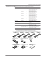
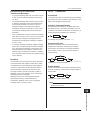
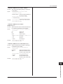
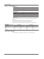
Standard Accessories
The standard accessories below are supplied with the instrument.
Name
Part Number
Qty.
Notes
Power cord
A1006WD
1
A1009WD
1
A1054WD
1
A1024WD
1
A1064WD
1
UL/CSA Standard Power Cord
Maximum rated voltage: 125 V;
Maximum rated current: 7A
VDE Standard Power Cord
Maximum rated voltage: 250 V;
Maximum rated current: 10 A
BS Standard Power Cord
Maximum rated voltage: 250 V;
Maximum rated current: 10 A
AS Standard Power Cord
Maximum rated voltage: 250 V;
Maximum rated current: 10 A
GB Standard Power Cord
Maximum rated voltage: 250 V;
Maximum rated current: 10 A
Rubber feet
Two rubber feet in one set.
A9088ZM
2
Measurement lead
758933
2 sets
Safety terminal cable. Red and black, 2 pcs. each
Alligator clip adapter 758922
2 sets
Safety terminal-to-alligator clip adapter. Red and black, 2 pcs. each
External I/O connectorB8060KA/A1519JD1 set15-pin connector for the 765601 and
connector cover, 1 pc. each
A1773JD/A1778JD1 set50-pin connector for the 765602 and
connector cover, 1 pc. each
User’s Manual
IM765601-01E
1
This manual
One of these power cords is supplied according to the suffix code.
UL, CSA Standard
A1006WD
D
F
BS Standard
A1054WD
Q
AS Standard
A1024WD
R
Measurement Lead
758933
Alligator Clip Adapter Set
758922
Rubber Feet
A9088ZM
Connector for EXT. I/O
For 765601 (15-pin, male)
For 765602 (50-pin, male)
GS820 User’s Manual
IM765601-01E
A1519JD
B8060KA
IM 765601-01E
VDE Standard
A1009WD
GB Standard
A1064WD
H
A1778JD
A1773JD
iii
Checking the Contents of the Package
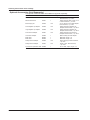
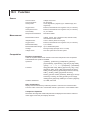
Optional Accessories (Sold Separately)
The optional accessories below are available for purchase separately.
Name
Part Number Minimum Q’ty
Notes
Measurement lead
758933
1
Safety terminal cable. Length: 1 m.
Red and black, 1 pc. each
Measurement lead
758917
1Safety terminal cable. Length: 0.75
m.Red and black, 1 pc. each
Banana plug set
758919
1 setφ4-mm plug/φ4-mm socket adapter.
Red and black, 1 pc. each
Small alligator clip adapter 758922
1 setSafety terminal-to-alligator clip adapter. Red and black, 1 pc. each
Large alligator clip adapter 758929
1 set
Safety terminal-to-alligator clip adapter. Red and black, 1 pc. each
Fork terminal adapter
758921
1 setSafety terminal-to-fork terminal
adapter. Red and black, 1 pc. each
Conversion adapter
1
BNC-to-safety terminal adapter
758924
BNC cable
366924
1
BNC-BNC, length: 1 m
BNC cable
366925
1
BNC-BNC, length: 2 m
Safety terminal adapter
758923
1 setSpring clamp type. Red and black, 1 pc. each
Safety terminal adapter
758931
1 setScrew-in type. Red and black, 1 pc. each
Synchronous operation cable 758960
1
RJ-11 cable, 6 pins, length: 1 m
iv
IM 765601-01E
Safety Precautions
This instrument is an IEC safety class I instrument (provided with a terminal for protective
earth grounding).
The general safety precautions described herein must be observed during all phases
of operation. If the instrument is used in a manner not specified in this manual, the
protection provided by the instrument may be impaired. Yokogawa Electric Corporation
assumes no liability for the customer’s failure to comply with these requirements.
The following symbols are used on this instrument.
Warning: handle with care. Refer to the user’s manual or service manual.
This symbol appears on dangerous locations on the instrument which require
special instructions for proper handling or use. The same symbol appears in the
corresponding place in the manual to identify those instructions.
Alternating current
ON (power)
OFF (power)
ON (power) state
OFF (power) state
IM 765601-01E
Safety Precautions
Be sure to comply with the precautions below. Not complying might result in
injury or death.
WARNING
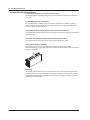
• Use the Correct Power Supply
Before connecting the power cord, ensure that the source voltage matches the
rated supply voltage of the instrument and that it is within the maximum rated
voltage of the provided power cord.
• Use the Correct Power Cord and Plug
To prevent the possibility of electric shock or fire, be sure to use the power
cord supplied by YOKOGAWA. The main power plug must be plugged into an
outlet with a protective earth terminal. Do not disable this protection by using an
extension cord without protective earth grounding.
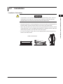
• Connect the Protective Grounding Terminal
Be sure to connect the protective earth to prevent electric shock before turning
ON the power. The power cord that comes with the instrument is a three-prong
type power cord. Connect the power cord to a properly grounded three-prong
outlet.
• Do Not Impair the Protective Grounding
Never cut off the internal or external protective earth wire or disconnect the
wiring of the protective earth terminal. Doing so poses a potential shock hazard.
• Do Not Operate with Defective Protective Grounding or Fuse
Do not operate the instrument if the protective earth or fuse might be defective.
Also, make sure to check them before operation.
• Do Not Operate in Explosive Atmosphere
Do not operate the instrument in the presence of flammable liquids or vapors.
Operation in such an environment constitutes a safety hazard.
• Do Not Remove Covers
The cover should be removed by YOKOGAWA’s qualified personnel only.
Opening the cover is dangerous, because some areas inside the instrument
have high voltages.
• Ground the Instrument before Making External Connections
Securely connect the protective grounding before connecting to the item under
measurement or to an external control unit.
If you are going to touch the circuit, make sure to turn OFF the circuit and check
that no voltage is present.
Be sure to comply with the precautions below. There are limitations to the
operating environment.
CAUTION
This product is a Class A (for industrial environment) product. Operation of this
product in a residential area may cause radio interference in which case the user is
required to correct the interference.
vi
IM 765601-01E
Waste Electrical and Electronic Equipment
Waste Electrical and Electronic Equipment (WEEE), Directive 2002/96/EC
(This directive is valid only in the EU.)
This product complies with the WEEE Directive (2002/96/EC) marking
requirement. This marking indicates that you must not discard this electrical/
electronic product in domestic household waste.
Product Category
With reference to the equipment types in the WEEE directive Annex 1, this
product is classified as a “Monitoring and Control instrumentation” product.
Do not dispose in domestic household waste. When disposing products in the EU,
contact your local Yokogawa Europe B. V. office.
New EU Battery Directive
New EU Battery Directive, DIRECTIVE 2006/66/EC
(This directive is valid only in the EU.)
Batteries are included in this product. This marking indicates they shall be sorted
out and collected as ordained in ANNEX II in DIRECTIVE 2006/66/EC.
Battery type
Lithium battery
You cannot replace batteries by yourself. When you need to replace batteries,
contact your local Yokogawa Europe B.V.office.
IM 765601-01E
vii
Conventions Used in This Manual
Markings
The following markings are used in this manual.
Improper handling or use can lead to injury to the user or damage
to the instrument. This symbol appears on the instrument to indicate
that the user must refer to the users manual for special instructions.
The same symbol appears in the corresponding place in the user’s
manual to identify those instructions. In the manual, the symbol is
used in conjunction with the word “WARNING” or “CAUTION.”
WARNING
Calls attention to actions or conditions that could cause serious or
fatal injury to the user, and precautions that can be taken to prevent
such occurrences.
CAUTION
Calls attentions to actions or conditions that could cause light injury to
the user or damage to the instrument or user’s data, and precautions
that can be taken to prevent such occurrences.
Note
Subheadings
Calls attention to information that is important for proper operation of
the instrument.
On pages that describe the operating procedures in chapters 3 through 17 and the
appendix, the following symbols are used to distinguish the procedures from their
explanations.
Procedure
Carry out the procedure according to the step numbers. All
procedures are written with inexperienced users in mind; experienced
users may not need to carry out all the steps.
Explanation This section describes the setup items and the limitations regarding
the procedures. It may not give a detailed explanation of the function.
For a detailed explanation of the function, see chapter 2.
<<Corresponding Command Mnemonic>>
Indicates a communication command that corresponds to the function described on the
procedural explanation page.
Displayed Characters and Terminology Used in the Procedural Explanations
Keys and Rotary Knob
Bold characters used in the procedural explanations indicate characters that are marked
on the panel key or the rotary knob.
SHIFT+Key
SHIFT+key means you will press the SHIFT key to turn ON the SHIFT key and then
press the panel key. In this state, the item marked in purple characters below the key is
controlled.
viii
IM 765601-01E
1
Contents
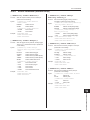
Checking the Contents of the Package.........................................................................................ii
Safety Precautions..........................................................................................................................v
Waste Electrical and Electronic Equipment................................................................................vii
New EU Battery Directive..............................................................................................................vii
Conventions Used in This Manual..............................................................................................viii
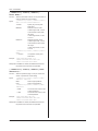
Front Panel....................................................................................................................... 1-1
Rear Panel........................................................................................................................ 1-2
Display Mode and Displayed Contents......................................................................... 1-3
Key Groups and Menus.................................................................................................. 1-5
Chapter 2 Explanation of Functions
2.1
2.2
2.3
2.4
IM 765601-01E
3
4
Chapter 1 Names and Functions of Parts
1.1
1.2
1.3
1.4
2
System Configuration and Block Diagram................................................................... 2-1
Product Features and System Configuration............................................................ 2-1
GS820 Features........................................................................................................ 2-1
System Configuration Diagram............................................................................... 2-2
Synchronous Operation by Connecting the I/O Terminals for Synchronous
Operation (SYNC IN/OUT)........................................................................................ 2-2
Block Diagram.............................................................................................................. 2-3
Source Measure Function of the GS820....................................................................... 2-4
GS820 Construction.................................................................................................... 2-4
Source Function and Measurement Function........................................................... 2-4
Combinations Source Function and Measurement Function.................................. 2-4
Source and Measurement Timing.............................................................................. 2-5
Basic Timing of Source and Measurement............................................................ 2-5
Setting the Timing Using Triggers............................................................................. 2-5
Sweep Function........................................................................................................... 2-6
Preset Sweep............................................................................................................ 2-6
programmable sweep............................................................................................... 2-6
Source.............................................................................................................................. 2-7
Source Range............................................................................................................... 2-7
Source Range........................................................................................................... 2-7
Voltage Range........................................................................................................... 2-7
Current Range........................................................................................................... 2-8
Source Function........................................................................................................... 2-8
Fixed Source Range and Auto Range........................................................................ 2-9
Source Action............................................................................................................... 2-9
Source Timing Adjustment Using the Source Delay ............................................. 2-10
Output ON/OFF and Zero Source..............................................................................2-11
Zero Source Function.............................................................................................2-11
DUT Protection Using the Limiter............................................................................ 2-12
Response Mode......................................................................................................... 2-13
Local Sense and Remote Sense............................................................................... 2-13
Offset Calibration....................................................................................................... 2-13
Measurement................................................................................................................. 2-14
Measurement Function and Measurement Range.................................................. 2-14
Measurement Function.......................................................................................... 2-14
Measurement Range.............................................................................................. 2-14
ix
5
6
7
8
9
10
11
12
13
14
15
16
17
18
Index
Contents
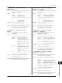
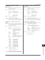
2.5
2.6
2.7
2.8
2.9
2.10
Fixed Measurement Range and Auto Range........................................................ 2-14
Measurement Mode................................................................................................... 2-15
Measurement Action.................................................................................................. 2-16
Measurement Timing Adjustment Using the Measurement Delay........................ 2-17
Highly Accurate Measurement and High-Speed Measurement............................. 2-17
Local Sense and Remote Sense........................................................................... 2-17
Integration time....................................................................................................... 2-17
Offset Calibration Function................................................................................... 2-17
Sweep............................................................................................................................. 2-18
Sweep Function of the GS820.................................................................................. 2-18
Basic Operation of Sweeps....................................................................................... 2-18
Linear Sweep.............................................................................................................. 2-19
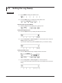
Log Sweep.................................................................................................................. 2-19
Start Level and Stop Level..................................................................................... 2-20
Step Count.............................................................................................................. 2-20
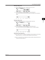
Programmable Sweep............................................................................................... 2-20
Program File............................................................................................................ 2-20
Contents of the Program File................................................................................ 2-21
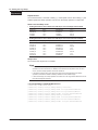
Single-Step Sweep..................................................................................................... 2-22
Repeat Count of Sweeps........................................................................................... 2-22
Starting the Sweep Operation................................................................................... 2-22
Triggering....................................................................................................................... 2-23
Overview..................................................................................................................... 2-23
Source Trigger........................................................................................................ 2-23
Measurement Trigger............................................................................................. 2-23
Sweep Start............................................................................................................. 2-23
Auxiliary Trigger Source........................................................................................ 2-25
Trigger Block Diagram............................................................................................... 2-25
Sweep Start Output, Trigger Output, and Auxiliary Trigger Output...................... 2-26
Trigger Hold................................................................................................................ 2-26
Sampling Error........................................................................................................... 2-26
Synchronization and External I/O................................................................................ 2-27
Synchronization Function and External I/O of the GS820..................................... 2-27
Inter-Channel Synchronization................................................................................. 2-27
Synchronous Operation
(I/O Terminal for Synchronous Operation (SYNC IN/OUT)) . ................................. 2-27
BNC I/O (TRIGGER IN/OUT and START IN/OUT)..................................................... 2-27
External I/O (Ext I/O).................................................................................................. 2-27
Channel Expansion Function................................................................................... 2-28
Computation.................................................................................................................. 2-29
Averaging (Moving Average)..................................................................................... 2-29
NULL Computation.................................................................................................... 2-29
Equation Computation.............................................................................................. 2-29
User-Defined File Format....................................................................................... 2-30
Comparison Operation.............................................................................................. 2-30
Store/Recall (Statistical Computation Value Display)................................................ 2-31
Executing and Stopping the Storage Operation..................................................... 2-31
Result File................................................................................................................... 2-31
Recalling Statistical Computation Values............................................................... 2-32
Reading the Storage Result via Communications.................................................. 2-33
Other Functions............................................................................................................. 2-34
USB Storage Function............................................................................................... 2-34
Non-Volatile Disk (GS820ROM)............................................................................. 2-34
IM 765601-01E
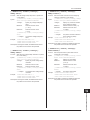
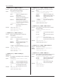
Contents
Volatile Disk (GS820RAM)...................................................................................... 2-35
Formatting the Disk................................................................................................ 2-35
USB Communication (Command Control by Way of USB-TMC)........................... 2-35
Ethernet Communications........................................................................................ 2-36
Command Control Using VXI-II............................................................................. 2-36
Panel Control Using a Browser............................................................................. 2-36
File Transfer with FTP Clients............................................................................... 2-36
Command Control Using Port 7655...................................................................... 2-36
GP-IB Communications............................................................................................. 2-36
RS-232 Communications........................................................................................... 2-36
Saving and Loading Setup Data............................................................................... 2-36
Selecting the Settings Applied at Power ON........................................................... 2-37
Setting the Display Brightness or Turning OFF the Display.................................. 2-37
Selecting the Decimal Point and Separator Notations of CSV Files..................... 2-37
Turning the Beep Sound ON/OFF............................................................................. 2-37
Error Log Display....................................................................................................... 2-37
Key Lock..................................................................................................................... 2-37
Self-Test...................................................................................................................... 2-37
Viewing the Product Information.............................................................................. 2-37
Updating the System Firmware................................................................................ 2-37
Handling Precautions..................................................................................................... 3-1
Installation....................................................................................................................... 3-3
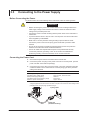
Connecting to the Power Supply................................................................................... 3-6
Turning the Power Switch ON/OFF................................................................................ 3-7
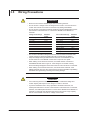
Wiring Precautions.......................................................................................................... 3-8
Setting the Line Frequency.......................................................................................... 3-10
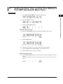
Setting the Date, Time, and the Time Difference from GMT
(Greenwich Mean Time).................................................................................................3-11
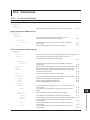
Chapter 4 Common Setup
4.1
4.2
4.3
4.4
4.5
4.6
Basic Operation of Keys and Rotary Knob and How to Enter Values........................ 4-1
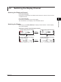
Switching the Display Channel...................................................................................... 4-3
Setting the Inter-Channel Synchronization Mode........................................................ 4-4
Setting the Timer Period................................................................................................. 4-5
Selecting the Wiring System (Remote Sense or Local Sense)................................... 4-6
USB Storage Function.................................................................................................... 4-8
Chapter 5 Source
5.1
5.2
5.3
5.4
5.5
5.6
5.7
5.8
5.9
5.10
5.11
5.12
IM 765601-01E
2
3
4
5
6
7
8
Chapter 3 Instrument Preparation and Common Operations
3.1
3.2
3.3
3.4
3.5
3.6
3.7
1
Switching the Source Function...................................................................................... 5-1
Setting the Source Range............................................................................................... 5-2
Setting the Limiter........................................................................................................... 5-4
Selecting the Source Waveform and Source Level...................................................... 5-7
Setting the Source Delay................................................................................................ 5-9
Selecting the Sweep Start Source................................................................................5-11
Selecting the Source Trigger........................................................................................ 5-12
Selecting the Response Mode..................................................................................... 5-13
Offset Calibration.......................................................................................................... 5-14
Setting the Pulse Base.................................................................................................. 5-15
Setting the Pulse Width................................................................................................ 5-16
Turning the Output ON/OFF and Zero Source............................................................ 5-17
xi
9
10
11
12
13
14
15
16
17
18
Index
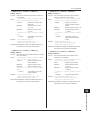
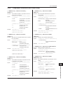
Contents
Chapter 6 Sweep
6.1
6.2
6.3
6.4
6.5
Setting the Linear Sweep................................................................................................ 6-1
Setting the Log Sweep.................................................................................................... 6-4
Setting the Programmable Sweep................................................................................. 6-7
Setting the Single-Step Sweep....................................................................................... 6-9
Starting the Sweep Operation...................................................................................... 6-10
Chapter 7 Measurement
7.1
7.2
7.3
7.4
7.5
7.6
7.7
Selecting the Measurement Mode................................................................................. 7-1
Selecting the Measurement Function............................................................................ 7-2
Setting the Measurement Range and Turning Auto Range ON/OFF.......................... 7-3
Setting the Integration Time........................................................................................... 7-5
Setting the Measurement Delay..................................................................................... 7-6
Selecting the Measurement Trigger............................................................................... 7-7
Auto Zero Function......................................................................................................... 7-8
Chapter 8 Computation
8.1
8.2
8.3
8.4
8.5
Averaging......................................................................................................................... 8-1
NULL Computation.......................................................................................................... 8-2
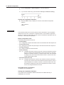
Equation Computation.................................................................................................... 8-3
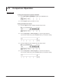
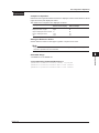
Comparison Operation................................................................................................... 8-6
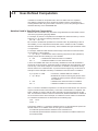
User-Defined Computation............................................................................................. 8-8
Chapter 9 Storing Measured Results and Recalling Statistical Computation
Values
9.1
9.2
Storing Measurement Results........................................................................................ 9-1
Recalling Statistical Computation Values..................................................................... 9-3
Chapter 10 BNC I/O, External I/O, and Synchronous Operation
10.1
10.2
10.3
10.4
10.5
10.6
Setting the BNC I/O Terminal (START IN/OUT, TRIGGER IN/OUT)............................ 10-1
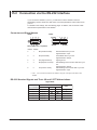
Pin Assignments of the External I/O Connector (EXT I/O)........................................ 10-3
Synchronous Operation............................................................................................... 10-5
Setting the Synchronous Mode between Units (Master and Slave)......................... 10-7
Setting the Auxiliary Trigger Source (AUX OUT)........................................................ 10-8
Channel Expansion Function....................................................................................... 10-9
Chapter 11 Other Functions
11.1
11.2
11.3
11.4
11.5
11.6
11.7
11.8
11.9
Saving the Setup Data...................................................................................................11-1
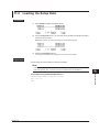
Loading the Setup Data.................................................................................................11-3
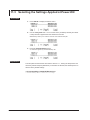
Selecting the Settings Applied at Power-ON...............................................................11-4
Selecting the Display Brightness and Turning the Display OFF...............................11-5
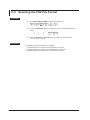
Selecting the CSV File Format......................................................................................11-6
Turning the Beep Sound ON/OFF.................................................................................11-7
Error Log Display...........................................................................................................11-8
Key Lock.........................................................................................................................11-9
Selecting the Loading Data Type for the Communication Command.....................11-10
Chapter 12 USB Interface
12.1
12.2
12.3
xii
USB Interface Functions and Specifications.............................................................. 12-1
Selecting the USB Interface Function......................................................................... 12-2
Viewing the VISA Setup Information........................................................................... 12-3
IM 765601-01E
Contents
Chapter 13 Ethernet Interface
13.1
13.2
13.3
13.4
13.5
Ethernet Interface Functions and Specifications....................................................... 13-1
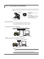
Connecting to the Network........................................................................................... 13-2
Setting the Network (TCP/IP)........................................................................................ 13-3
Viewing the Network Settings...................................................................................... 13-6
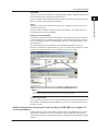
Web Server Function.................................................................................................... 13-7
Chapter 14 GP-IB Interface
14.1
14.2
14.3
14.4
14.5
About the IEEE.488.2-1992 Standard........................................................................... 14-1
GP-IB Interface Functions and Specifications........................................................... 14-3
Connecting the GP-IB Cable........................................................................................ 14-4
Setting the GP-IB Address............................................................................................ 14-5
Responses to Interface Messages............................................................................... 14-6
Chapter 15 RS-232 Interface
15.1
15.2
15.3
15.4
RS-232 Interface Functions and Specifications......................................................... 15-1
Connection via the RS-232 Interface........................................................................... 15-2
Handshaking.................................................................................................................. 15-4
Setting the RS-232 Interface......................................................................................... 15-5
Chapter 16 Communication Commands
16.1
16.2
16.3
16.4
IM 765601-01E
Program Format............................................................................................................ 16-1
16.1.1 Symbols Used in the Syntax......................................................................... 16-1
16.1.2 Messages........................................................................................................ 16-1
16.1.3 Commands...................................................................................................... 16-3
16.1.4 Response........................................................................................................ 16-5
16.1.5 Data.................................................................................................................. 16-5
Commands..................................................................................................................... 16-7
16.2.1 A List of Commands....................................................................................... 16-7
16.2.2 Output Commands (OUTPut Group)........................................................... 16-13
16.2.3 Sweep Commands (SWEep Group)............................................................ 16-14
16.2.4 Source Commands (SOURce Group)......................................................... 16-15
16.2.5 Measurement Commands (SENSe Group)................................................. 16-25
16.2.6 Computation Commands (CALCulate Group)........................................... 16-29
16.2.7 Measured Value Read Commands (INITiate, FETCh, READ,
MEASure Group).................................................................................................. 16-31
16.2.8 Trigger Commands (STARt and TRIGger Groups).................................... 16-32
16.2.9 Store/Recall Commands (TRACe Group)................................................... 16-33
16.2.10 Synchronization Commands (SYNChronize Group)................................. 16-35
16.2.11 External I/O Commands (ROUTe Group).................................................... 16-36
16.2.12 System Commands (SYSTem Group)......................................................... 16-37
16.2.13 Status Commands (STATus Group)............................................................ 16-42
16.2.14 Common Commands................................................................................... 16-43
Status Reports............................................................................................................. 16-45
16.3.1 Status Reports.............................................................................................. 16-45
16.3.2 Status Byte.................................................................................................... 16-46
16.3.3 Standard Event Register.............................................................................. 16-47
16.3.4 Source Event Register................................................................................. 16-49
16.3.5 Measurement Event Register...................................................................... 16-51
16.3.6Output Queue and Error Queue.................................................................. 16-52
Sample Programs........................................................................................................ 16-53
16.4.1 Before Programming.................................................................................... 16-53
xiii
1
2
3
4
5
6
7
8
9
10
11
12
13
14
15
16
17
18
Index
Contents
16.4.2 Interface Access Function........................................................................... 16-54
16.4.3Sample 1 (Example of Reading the Measured Results during Free Run
Using Constant Period Trigger).........16-56
16.4.4Sample 2 (Example of Generating a Trigger from the PC and Reading the
Measured Results)...............................16-58
16.4.5Sample 3 (Example of Changing and Measuring Simultaneously on Two
Channels Using Single-Step Sweep)16-60
Chapter 17 Troubleshooting and Maintenance
17.1
17.2
17.3
17.4
17.5
17.6
Troubleshooting............................................................................................................ 17-1
Error Code Description and Corrective Actions......................................................... 17-3
Self-Test......................................................................................................................... 17-7
Viewing the Product Information................................................................................. 17-9
Updating the System Firmware.................................................................................. 17-10
Recommended Replacement Parts and Maintenance..............................................17-11
Chapter 18 Specifications
18.1
18.2
18.3
18.4
18.5
18.6
18.7
18.8
Source Section.............................................................................................................. 18-1
Measurement Section................................................................................................... 18-3
Function......................................................................................................................... 18-4
External I/O Section (BNC (TRIGGER IN/OUT and START IN/OUT), Digital I/O (EXT I/O),
and I/O for Synchronous Operation (SYNC IN/OUT))................................................. 18-5
Interface......................................................................................................................... 18-6
Contents of the Factory Default Setup File (Default.txt)............................................ 18-7
General Specifications.................................................................................................. 18-8
External Dimensions................................................................................................... 18-12
Index
xiv
IM 765601-01E
Chapter 1
1.1
Names and Functions of Parts
1
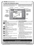
Front Panel
Names and Functions of Parts
2
Remote indicator
Illuminates when the GS820 is in remote mode (controlled via communications). → Sections 14.2 and 15.1
3
KEY LOCK indicator
Illuminates when key lock is ON. → Section 11.8
Master indicator
Illuminates when set as a master unit in synchronized operation. → Section 10.4
4
Sampling error indicator
Illuminates when a sampling error occurs in sweep start, source trigger, or measurement trigger.
→ Sections 5.7, 6.5, and 7.6
5
Display → Section 1.3
Soft keys
Selects items on the soft key menu that appears when setting up the GS820.
→ Section 4.1
6
GS820
MULTI CHANNEL SOURCE MEASURE UNIT
SAMPLE
ERROR
MASTER
KEY LOCK
REMOTE
BS
DISPLAY
ESC
CH
STORE
CONFIG
MEASURE
RANGE
SETUP
ERROR
MISC
INFO
RANGE
SHFT
AUTO
POWER
CONFIG
NULL
PULSE
MATH
SWEEP
AUTO
COMPARE
CONTROL
V/I
MODE
CONFIG
LOCAL
SYNC
TIMER
V/I
START
LIMIT
TRIG
HOLD
8
9
4
5
6
1
2
3
0
.
+/-
KEYLOCK
CH 1
SOURCE
MODE
7
ZERO
OUTPUT
ZERO
CONFIG
OUTPUT
CONFIG
4WIRE
SENSE
18V
MAX
Hi
0.5V
MAX
Lo
CONFIG
18V
MAX
4WIRE
SENSE
18V
MAX
Hi
0.5V
MAX
Lo
ALL TERMINALS 250V MAX TO
Power switch
→ Section 3.4
Handle
Used to carry the GS820.
→ Section 3.1
ESC (DISPLAY) key
Switches the display or
clears a soft key menu.
→ Section 4.1
CH 2
CONFIG
18V
MAX
7
Rotary knob, numeric keys, and cursor
keys
Sets values or selects setup data or items.
→ Section 4.1
8
Output control key
Press to generate output or zero source.
→ Section 5.12
9
Output terminals
Connects the measurement leads that
come with the package.
→ Sections 3.5 and 4.5
10
11
Trigger control key
A key used to generate a sweep start or source trigger or to hold a trigger.
→ Sections 2.6 and 6.5
Setup and execution keys
Keys used to change the settings or execute an operation.
Press a setup key to show the respective setup item. → Sections 1.4 and 4.1
12
13
SHIFT key
The keys enter the shifted state when you press the SHIFT key and the SHIFT key
illuminates.
In this state, the item marked in purple characters below the key is controlled.
14
15
16
17
18
Index
IM 765601-01E
1-1
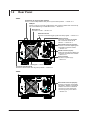
1.2
Rear Panel
765601
I/O terminals for synchronized operation
Used to connect multiple GS820s and perform synchronized operation. → Section 10.3
USB port
Used to connect to a PC with a USB interface and control the GS820 with commands by
way of the USB storage or USB-TMC function. → Section 4.6
Ethernet port
Connects to a LAN. → Section 13.2
BNC I/O terminals
Receives or transmits trigger signals and sweep signals. → Section 10.1
USB LINK
SYNC
ACT
ETHERNET
100BASE-TX
TRIGGER
IN/OUT
START
IN/OUT
GP-IB
(IEEE 488)
EXT I/O
OUT
External I/O connector (15 pins)
Receives or transmits digital signals
or transmits comparison results.
→ Section 10.2
SERIAL
(IRS-232)
IN
GP-IB connector
Used when controlling the GS820
with commands via the GP-IB
interface. → Section 14.3
RS-232 connector (9 pins)
Used when controlling the GS820 with
commands via the RS-232C interface.
→ Section 15.2
Power connector
Connects to a power supply.
→ Section 3.3
100-120/220-240 V AC~
250 VA MAX 50/60 Hz
Cooling fan → Section 3.2
Functional ground terminal
Shields the measurement cable at ground potential. → Section 3.5
765602
IN
OUT
ETHERNET
100BASE-TX
ACT
TRIGGER
IN/OUT
START
IN/OUT
GP-IB
(IEEE 488)
EXT I/O
SYNC
USB LINK
100-120/220-240 V AC~
250 VA MAX 50/60 Hz
1-2
External I/O connector (50 pins)
Receives or transmits 16-bit digital
I/O signals in addition to the signals
similar to those of the external I/O
connector (15 pins) and RS-232
connector (9 pins) of the 765601.
→ Section 10.2
IM 765601-01E
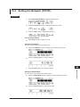
1.3
1
Display Mode and Displayed Contents
Names and Functions of Parts
2
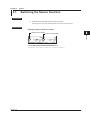
Display Mode
ESC (DISPLAY) to switch the display mode.
2-Channel Display
3
The left half of the display shows CH1 information, and the right half shows CH2
information. The channel that is currently controllable is displayed with a frame. Press
CH to switch the controllable channel.
Channel number
Controllable channel
4
Source levelMeasured value
Auto measurement range ON
Measurement range
Auto source range ON
Source range
Comparison result display
Status indicator
High limiter indicator
5
6
7
High limiter
Low limiter value
value
Wiring system indicator Source waveform and sweep mode indicator
8
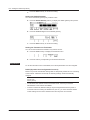
1-Channel Display
Displays information of the currently controllable channel.
9
Channel number
Source level
Measured value
Auto measurement range ON
Measurement range
Auto source range ON
Source range
11
12
Comparison result display
NULL computation indicator
Equation computation indicator
Wiring system indicator
Low limiter value
Low limiter indicator
Source waveform and sweep mode indicator
High limiter
value
Status
indicator
10
13
14
Displayed Contents
15
Channel Number
CH1 or CH2
16
Status Indicator
Displays the various wait conditions during operation.
WaitTrigger: Waiting for trigger
WaitStart:
Waiting for sweep start
Calculating: Sweep in preparation
17
18
Index
IM 765601-01E
1-3
1.3 Display Mode and Displayed Contents
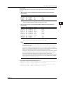
Source Waveform and Sweep Mode Indicator
Displays the combination of the source waveform and sweep mode ON/OFF. The
following four combinations are available.
Indication
Source Waveform
Sweep
DC
Pls
DC Swp
Pls Swp
DC
Pulse
DC
Pulse
OFF
OFF
ON
ON
Wiring System Indicator
Displays the selected wiring system.
2W/2Wire: Local sense
4W/4Wire: Remote sense
Equation Computation Indicator
Displays “MATH” when equation computation is ON.
NULL Computation Indicator
Displays “Null” when NULL computation is ON.
Comparison Result Display
Displays the judgment result of the comparison.
High:Greater than the upper limit
In: Within the range
Low: Less than the lower limit
High Limiter and Low Limiter Values
Displays the high limiter and low limiter values.
High Limiter Indicator
Highlighted when the high limiter is activated.
Low Limiter Indicator
Highlighted when the low limiter is activated.
Source Level
Displays the current source level. VS/IS at the front indicates the source function (voltage
source or current source).
Measured Value
Displays the current measured value. IM/VM at the front indicates the measurement
function (voltage measurement or current measurement). The display indicates “-----”
when measurement is not performed and “+OVER” or “-OVER” when the measurement
is over-the-range.
Auto Range ON
Displayed when auto range is selected.
Source Range or Measurement Range
Displays the current range.
1-4
IM 765601-01E
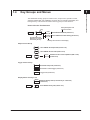
1.4
1
Key Groups and Menus
Names and Functions of Parts
2
The GS820 has five key groups for each function, output control, operation control,
SOURCE, MEASURE, and COMMON, as well as keys for switching the display and
locking the keys. This section introduces each key group in a tree structure.
3
How to View the Tree Structure
SHIFT
+
Limit
On Off
SWEEP
LIMIT
Activated when the
SHIFT key is pressed
followed by the key
4
Setup description and
reference section
Key
5
Turns ON/OFF the limiter (section 5.3)
Tracking
On Off
Turns ON/OFF the limiter tracking (section 5.3)
6
Soft key menu shown on the display
7
Output Control Group
OUTPUT
ZERO
SHIFT
+
ZERO
CONFIG
Turns ON/OFF the output mode (section 5.12)
8
Turns ON/OFF the zero state (section 5.12)
Zero Z
HiZ LoZ
9
Switches the zero source impedance (HiZ or LoZ)
(section 5.12)
10
Trigger Control Group
START
11
Generates sweep start (section 6.5)
TRIG
Generates a manual trigger (section 2.6)
HOLD
Trigger hold (section 2.6)
12
13
Display Switch and Key Lock
DISPLAY
ESC
SHIFT
14
Switches display mode (1 channel only or 2 channels)
(section 4.2)
15
Turns ON/OFF the key lock (section 11.8)
+
KEYLOCK
16
17
18
Index
IM 765601-01E
1-5
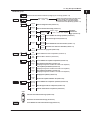
1.4 Key Groups and Menus
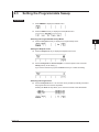
SOURCE group
V I
CONFIG
PULSE
Switches the source function (voltage (VS) or current (IS)) (section 5.1)
Shape
DC Pulse
S.Delay
***
External Aux
Sweep Start
Aux Timer1 Timer2 MeasEnd
SrcTrig
***
External Aux
Source Trigger
Aux Timer1 Timer2 MeasEnd
ZeroCal
Exec
CONFIG
+
PULSE
SWEEP
LIMIT
SHIFT
SWEEP
+
LIMIT
Sets the source delay (section 5.5)
SwpStart
***
Response
***
SHIFT
Selects the source waveform (DC or pulse source) (section 5.4)
Selects the sweep
start (section 5.6)
Selects the source
trigger (section 5.8)
Response
Selects the response mode (normal or stable)
Normal Stable (section 5.8)
Executes output offset calibration (section 5.9)
Pulse
Base
Sets the pulse base for pulse generation (section 5.10)
P.Width
***
Sets the pulse width for pulse generation (section 5.11)
Mode
***
Repeat
***
Off
Linear
Selects the sweep mode (off, linear,
SweepMode
Log Program Single log, program, or single step)
(sections 6.1 to 6.4)
Sets the sweep repeat count (sections 6.1 to 6.3)
(Displayed only when linear, log, or programmable sweep is selected)
Start
Level
Sets the sweep start level (sections 6.1 and 6.2)
(Displayed only when linear or log sweep is selected)
Stop
Level
Sets the sweep stop level (sections 6.1 and 6.2)
(Displayed only when linear or log sweep is selected)
Step
Level
Sets the sweep step level (section 6.1)
(Displayed only when linear sweep is selected)
Step
Count
Sets the number of sweep steps (section 6.2)
(Displayed only when log sweep is selected)
View
Displays the contents of the pattern file (section 6.3)
(Displayed only when programmable sweep is selected)
Select
File
Selects a pattern file (section 6.3)
(Displayed only when programmable sweep is selected)
Limit
On Off
Turns ON/OFF the limiter (section 5.3)
Tracking
On Off
Turns ON/OFF the limiter tracking (section 5.3)
High
Limit
Sets the upper limiter value (section 5.3)
(Displayed only when limiter tracking is OFF)
Low
Limit
Sets the lower limiter value (section 5.3)
(Displayed only when limiter tracking is OFF)
RANGE
Increases the source range (section 5.2)
Decreases the source range (section 5.2)
SHIFT
1-6
+
AUTO
Turns ON/OFF the auto source range (section 5.2)
IM 765601-01E
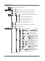
1.4 Key Groups and Menus
1
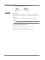
MEASURE group
I
Switches the measurement function (voltage (V) or current (I)) (section 7.2)
MODE
SHIFT
+
V
I
Off
Fixed
Measurement Mode
Auto V-Meter I-Meter R-Meter
MODE
CONFIG
PULSE
IntgTime
***
Sets the integration time (section 7.4)
M.Delay
***
Sets the measurement delay (section 7.5)
MeasTrig
***
SrcChg Aux
Average
***
Average
On Off
Count
***
AutoZero
***
SHIFT
+
CONFIG
NULL
MATH
COMPARE
SHIFT
+
MATH
COMPARE
Selects the measurement mode (Off, fixed
function (Fixed), auto function (Auto),
voltmeter (V Meter), ammeter (I Meter),
or resistance meter (R Meter)) (section 7.1)
Turns ON/OFF the average operation (section 8.1)
ZeroCal
Exec
Executes zero reference calibration (section 7.7)
Wire
2W 4W
Selects the wiring system (section 4.5)
Null
On Off
Turns ON/OFF the NULL computation (section 8.2)
Null
Value
7
8
9
Turns ON/OFF the equation computation (section 8.3)
Param
A
Sets equation parameter A (section 8.3)
(Displayed only when variable A is used in the equation)
Param
B
Sets equation parameter B (section 8.3)
(Displayed only when variable B is used in the equation)
Param
C
Sets equation parameter C (section 8.3)
(Displayed only when variable C is used in the equation)
View
Displays the equation (section 8.3)
Select
File
Selects the equation definition file (section 8.3)
10
11
12
13
14
Turns ON/OFF the comparison operation (section 8.4)
Upper
Sets the upper limit for comparison (section 8.4)
Lower
Sets the lower limit for comparison (section 8.4)
15
16
RANGE
Increases the measurement range (section 5.2)
17
Decreases the measurement range (section 5.2)
SHIFT
+
AUTO
5
Sets the NULL reference (section 8.2)
Math
On Off
Compare
On Off
3
6
Sets the average count (section 8.1)
Turns ON/OFF the auto zero function (section 7.7)
2
4
Selects the
Measure Trigger
Aux Timer1 Timer2 Imm SwpEnd measurement
trigger (section 7.6)
AutoZero
On OFF
Names and Functions of Parts
V
18
Turns ON/OFF the auto measurement range (section 5.2)
Index
IM 765601-01E
1-7
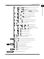
1.4 Key Groups and Menus
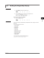
COMMON group
STORE
Turns ON/OFF the storage function (section 9.1)
CONFIG
SHIFT
+
STORE
CONFIG
Count
***
MakeFile
On Off
Recall
SETUP
MISC
Save
Setup
View
PowerOn
Setup
Load
Setup
SHIFT
+
SETUP
MISC
Remote
I/F
Sets the number of points to be stored (store count) (section 9.1)
Turns ON/OFF the stored results file generation function (section 9.1)
Displays the stored statistical computation results (section 9.2)
RamDisk
Saves the setup data to the RAM disk (GS820RAM) (section 11.1)
Setup1
Saves the setup data to Setup 1 (section 11.1)
Setup2
Saves the setup data to Setup 2 (section 11.1)
Setup3
Saves the setup data to Setup 3 (section 11.1)
Setup4
Saves the setup data to Setup 4 (section 11.1)
Displays the contents of a setup file (section 11.2)
Selects the setup used when the GS820 is powered up (section 11.3)
Loads a setup (section 11.2)
GPIB
***
RS232
Sets the GP-IB address (section 14.4)
BaudRate
***
DataBit
7 8
Parity
***
StopBit
1 2
Flow
***
Term
***
LAN
DHCP
On Off
Selects the
BaudRate
RS-232 baud
9600 14400 19200 38400 57600 115200 rate
(section 15.4)
Switches the RS-232 data length (7 or 8) (section 15.4)
Parity
None Even Odd
Selects the RS-232 parity
(none, odd, or even) (section 15.4)
Switches the RS-232 stop bits (1 or 2) (section 15.6)
Selects the RS-232 flow control
FlowControl
None XON CTS/RTS (none, XON-OFF, or CTS-RTS)
Terminator
CR LF CR+LF
(section 15.4)
Selects the RS-232 transmission
delimiter (CR, LF, or CR+LF)
(section 15.4)
Turns ON/OFF the Ethernet DHCP function (section 13.3)
IP
Address
Enter
Sets a static Ethernet IP address (section 13.3)
(Displayed only when DHCP is OFF)
Subnet
Mask
Enter
Sets a static Ethernet subnet mask (section 13.3)
(Displayed only when DHCP is OFF)
Default
Gateway
Enter
Sets a static Ethernet default gateway
(section 13.3) (Displayed only when DHCP is OFF)
Terminator
LF CR+LF
Sets the Ethernet transmission
delimiter (CR, LF, or CR+LF)
(section 13.3)
Overview Shows a list of Ethernet settings (section 13.4)
Term
***
USB
***
VISA
Info
CR
USB Mode
Storage USB-TMC
Selects the USB function (storage function
or USB communication function)
(section 12.2)
Displays a list of VISA information (section 12.3)
Continues to the next page
1-8
IM 765601-01E
1.4 Key Groups and Menus
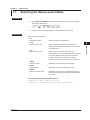
COMMON group
1
Continued from the previous page
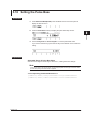
StartBNC
Input
Output
Selects the sweep start BNC terminal (input or output)
(section 10.1)
TrigBNC
Input
Output
Selects the trigger BNC terminal (input or output)
(section 10.1)
LineFrequency
50Hz 60Hz Auto
Detected
**Hz
Display
***
1
Brightness
2
3
,
Separate
,
Beep
On Off
4
Selects the line frequency (section 3.6)
4
5
Selects the display brightness (section 11.4)
Turns OFF the display (section 11.4)
DecPoint
.
3
Displays the detected line frequency (section 3.6)
Off
Exec
CSV
Setting
2
Auxiliary Out
Selects the auxiliary trigger
MeasBusy Timer1 Timer2 Through signal source (section 10.5)
Aux Out
***
LineFreq
***
Names and Functions of Parts
External
I/O
;
6
Selects the decimal point for CSV files (section 11.5)
7
Selects the separator for CSV files (section 11.5)
Turns ON/OFF the beep sound (section 11.6)
Clock
Adjust
Time
Adjust
Edit
Zero
Adjust
Time
Zone
Display
Test
Disk
Format
Set
9
Resets the seconds to zero (section 3.7)
Edit
Set
Sets the time difference from GMT
(section 3.7)
10
Executes a display test (section 17.3)
Key
Executes a key test (section 17.3)
SelfTest
Executes a self-test (section 17.3)
Exec
8
Sets the time (section 3.7)
11
12
Formats the GS820ROM disk (section 4.6)
Firmware
Updates the system firmware (section 17.5)
Update
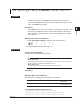
SYNC
TIMER
Channel
Sync
Async
Operation
Master
SHIFT
+
SYNC
TIMER
ERROR
Slave
13
Selects the inter-channel synchronization mode (section 4.3)
14
Selects synchronization function between units (section 10.4)
Expand
On Off
Turns ON/OFF the channel expansion (section 10.6)
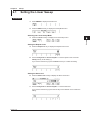
Timer1
***
Sets the Timer 1 period (section 4.4)
Timer2
***
Sets the Timer 2 period (section 4.4)
Timer
Sync
Synchronizes phases of Timer 1 and Timer 2 (section 4.4)
Clear
Shows or clears the error log (section 11.7)
15
16
17
18
INFO
SHIFT
+
ERROR
Shows the product information (section 17.4)
Index
INFO
IM 765601-01E
1-9
Chapter 2
2.1
Explanation of Functions
1
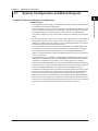
System Configuration and Block Diagram
2
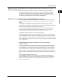
GS820 Features
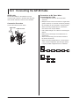
• The GS820 is a source measure unit that has two mutually isolated channels that can
be configured and operated independently.
• The source function (VS or IS) on each channel can be switched even while the output
is ON. In addition, the measurement function (VM or IM) can be switched at any time.
• The GS820 compares the measured value of each channel to a threshold value
(comparison operation function) and provides a terminal for delivering the comparison
result.
• By using the external I/O connector on the rear panel, 2-bit (765601) or 16-bit (765602)
digital output that can be driven from CH1 can be controlled in sync with the source
operation. In addition, the 2-bit (765601) or 16-bit (765602) digital input can be output
to a result file along with the measurement results.
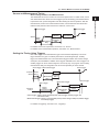
• The I/O terminals for synchronous operation (SYNC IN/OUT) of multiple GS820s can
be connected in a daisy chain to allow synchronization of output control and trigger.
This increases the number of channels that can be controlled simultaneously. In
addition, a channel expansion function is available that allows synchronous operation
of up to 10 channels.
• The GS820 has a built-in 12-MB non-volatile storage (GS820ROM) for storing various
settings and a 16-MB volatile storage (GS820RAM) for storing measurement results
and the like. If the GS820 is connected to your PC using USB, the two storage
memories becomes accessible from your PC as external disks. Because settings and
results are saved in a general text file or CSV file, you can use a text editor, a generalpurpose spreadsheet application, or the like to edit or draw graphs on your PC.
In addition to the storage function, the USB can be used to perform command control
by way of the USB-TMC protocol. Furthermore, command control can be performed
by way of other communication interfaces such as GP-IB, RS-232, and Ethernet
(VXI-11 protocol/7655 command socket). These interfaces allow multiple GS820s to
be controlled simultaneously using commands. The Ethernet communication also has
an FTP server function for the built-in storage and an HTTP server function that allows
information to be viewed and the GS820 to be controlled from a browser.
Explanation of Functions
Product Features and System Configuration
3
4
5
6
7
8
9
10
11
12
13
14
15
16
17
18
Index
IM 765601-01E
2-1
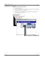
2.1 System Configuration and Block Diagram
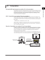
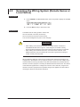
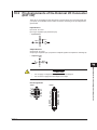
System Configuration Diagram
Command control
START
SYNC IN
RS-232
GP-IB
USB (USB-TMC)
Ether (VXI-11)
PC
Connect as an external
Communication line
disk of a PC by way of
the USB storage function
GS820
TRIG
GS820 GS820
RAM
ROM
AUX
Internal storage
START
TRIG
AUX
OUTPUT
OUTPUT
ZERO
ZERO
SYNC OUT
CH2
CH1
Analog/digital I/O
Digital
input
Digital
output
Analog
Analog
Comparison
result
Comparison
result
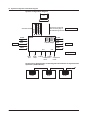
Synchronous Operation by Connecting the I/O Terminals for Synchronous
Operation (SYNC IN/OUT)
2-2
IN OUT
SYNC
IN OUT
SYNC
IN OUT
SYNC
GS820
GS820
GS820
IM 765601-01E
2.1 System Configuration and Block Diagram
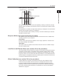
1
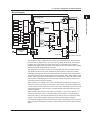
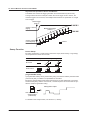
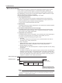
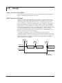
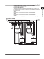
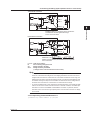
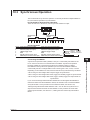
Block Diagram
Digital block
CH2 analog block
2
CH1 analog block
Rs
+ Current
-
ADC
LED
KEY
FPGA
Switch
Control
SYNC I/F
GP-IB I/F
FLASH ROM
PLD
SDRAM
LAN I/F
CPU
DIO I/F
+
Limiter
-Limit
DAC
RS232 I/F
Source
DAC
DC/DC
DC/DC
-
4
SENSE Hi
Sense
Vo
(VL)
I
Io
(IL)
SENSE Lo
Vm
R1
5
DUT*
+
R2
Vs
Power Supply
AC/DC
-
SW1
V
3
Sense
+ Voltage
+Limit
DAC Vp
OUTPUT Hi
Explanation of Functions
VFD
6
7
I
V
+
8
OUTPUT Lo
Power Amp
* DUT: Device Under Test
The GS820 consists of a digital section at ground potential and analog sections that are
insulated from the digital section. The CH1 and CH2 analog sections are also mutually
insulated. The power supply is a single output source. The desired circuit voltage is
supplied to the digital section through a non-isolated DC-DC converter and to the analog
sections through an isolated DC-DC converter.
The digital section consists of a CPU, FPGA, memories, and various interface circuits.
The FPGA provides not only CPU peripheral circuits but also an interface for serially
transferring the setup data of D/A converters (DACs) and switches to the analog section.
The analog sections consist of fast, highly accurate op-amps, highly stable resistors, and
the like. A PLD is employed at the interface to the digital section. The PLD sets the serial
data sent from the digital section to each DAC and controls the operation sequence of
each switch when the range is changed.
When operating as a voltage source, SW1 is connected to V, and source voltage Vo is
a product of source DAC value Vs and R2/R1. If load current IL increases positively and
IL × Rs exceeds positive limiter DAC value Vp, the diode of the limiter circuit will turn ON
and suppress the load current to Vp/Rs. A similar operation takes place when the load
current is negative.
When operating as a current source, SW1 is connected to I, and source current Io is a
product of source DAC value Vs and (R2/R1)/Rs. If load voltage VL exceeds positive
limiter DAC value Vp, the diode of the limiter circuit will turn ON and suppress the load
voltage to Vp. A similar operation takes place when the load voltage is negative.
The GS820 is equipped with a measurement circuit that is separate from the source and
limiter circuits and measures the voltage or current that is received using A/D converters
(ADC).
9
10
11
12
13
14
15
16
17
18
Index
IM 765601-01E
2-3
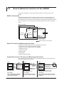
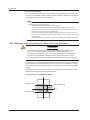
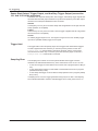
2.2
Source Measure Function of the GS820
This section describes the source measurement function, the basic function of the
GS820.
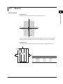
GS820 Construction
The GS820 is equipped with two analog channels with each channel consisting of a
constant voltage source (VS), a constant current source (IS), a voltmeter (VM), and an
ammeter (IM). The two channels are isolated. Each channel allows voltage sensing using
a two-wire system or a four-wire system by switching between local sense and remote
sense.
GS820 construction
CH2
CH1
OUTPUT Hi
A
SENSE Hi
Ammeter
IM
Constant
voltage source
VS
Constant
current source
IS
Voltmeter*
VM
DUT
V
SENSE Lo
OUTPUT Lo
* For DUT voltage measurement
Used to measure a four-wire system
Source Function and Measurement Function
The GS820 has the following source and measurement functions.
• Voltage source and current measurement (VS&IM)
• Current source and voltage measurement (IS&VM)
• Voltage source (VS)
• Current source (IS)
• Voltmeter (VM)
• Ammeter (IM)
• Resistance meter (IS&VM)
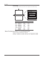
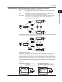
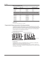
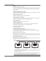
Combinations Source Function and Measurement Function
You can select the source function or the measurement function on each channel and
arbitrarily combine the two channels.
GS820
CH1
CH2
Source
Source
Voltage
source
Voltage
source
DUT
Power
supply 1
Multiple power
source device
Power
supply 2
GS820
CH1
Source
CH2
Measure
Voltage DUT
source
Analog or
digital IC
Voltage
measurement
GS820
CH1
Source and
measure
CH2
Source and
measure
DUT
Power
supply
Current measurement
IC
Voltage source
Current source
(electronic load)
Voltage measurement
CH1: Source mode
CH2: Source mode
CH1: Source mode
CH2: Measurement mode
CH1: Source and measurement mode
CH2: Source and measurement mode
• DUT example
CPU, multi-core MPU, embedded
device, hybrid IC, disk drive, and
various board assemblies
• DUT example
Op Amp, comparator, logic IC,
and various board assemblies
• DUT example
Three-terminal regulator, DC-DC converter,
bipolar transistor, FET, and various board
assemblies
2-4
IM 765601-01E
2.2 Source Measure Function of the GS820
1
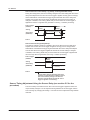
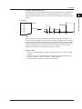
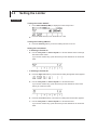
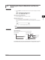
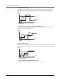
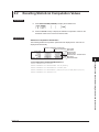
Source and Measurement Timing
Basic Timing of Source and Measurement
Source trigger
Source
Source trigger
Source
delay
Measurement
delay
5
Integration
time
6
For details on the source operation, see section 2.3, “Source.”
For details on the measurement operation, see section 2.4, “Measurement.”
7
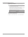
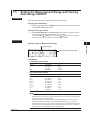
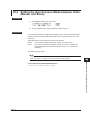
Setting the Timing Using Triggers
The source trigger and measurement trigger can be selected separately. The source
trigger includes two types of constant period timers, external signal input, auxiliary
trigger, and measurement end. The measurement trigger includes source level change,
sweep end, and immediate in addition to the triggers available for the source trigger. The
auxiliary trigger can be an external signal or an event by way of a program. Source delay,
measurement delay, and integration time can be set separately for each channel.
Source trigger Measurement trigger
Channel 1 Source
Source delay 1
Measurement
delay 1
Source trigger
3
4
Auto zero
measurement
Measure
2
Explanation of Functions
The GS820 has two source modes: DC source and pulse source. In either mode, source
and measurement are carried out with a trigger input as the starting point. Measurement
is performed over a preset integration time after starting the source operation. After the
measurement, the auto zero measurement function, which measures the internal zero
reference and performs offset correction in real-time, can be used.
8
9
10
Source trigger
Measure
11
Integration
time 1
12
Source trigger
Measurement trigger
13
Measure
Channel 2
Source
Source
delay 2
Measurement
delay 2
Integration
time 2
14
Source trigger: Timers 1 and 2 (constant period), external trigger, auxiliary trigger, and
measurement end)
Measurement trigger: Timers 1 and 2 (constant period), source change, sweep end, external trigger,
and auxiliary trigger)
For details on triggering, see section 2.6, “Triggering.”
15
16
17
18
Index
IM 765601-01E
2-5
2.2 Source Measure Function of the GS820
Asynchronous Operation of Source and Measure
The GS820 can execute the trigger generation and measurement asynchronously.
The figure below shows an example in which the source trigger is set to Timer1, the
measure trigger is set to Timer2, and multiple measurements are performed on a single
source trigger.
Source trigger
(Timer 1)
Channel 1 source
(Apply)
Measurement trigger
(Timer 2)
Channel 2 source
(Load response)
Sweep Function
: Measure
Preset Sweep
By setting parameters, a preset sweep (continuous output, linear sweep, or log sweep)
can be performed in each source mode.
Source Mode
No Sweep
Linear Sweep
Log Sweep
DC source
Pulse source
programmable sweep
A programmable sweep can be performed by using user-defined arbitrary waveform data
(CSV format) that you edited on a spreadsheet or text editor.
Because a programmable sweep allows the timing and control parameters to be swept
simultaneously along with the source level, a control sequence can be executed in sync
with the waveform generation timing.
Sweep pattern output
User-defined arbitrary
waveform data
(CSV format)
For details on the sweep function, see section 2.5, “Sweep.”
2-6
IM 765601-01E
2.3
1
Source
2
Explanation of Functions
Source Range
Source Range
3
Indicates the range that the GS820 can generate or measure.
I
4
3.2 A
5
–18 V
–7 V
1.2 A
7V
–1.2 A
18 V
6
V
7
8
–3.2 A
9
The source range is divided into several voltage ranges and current ranges. Voltage
ranges and current ranges are used as source ranges or limiter ranges, respectively.
10
Voltage Range
The voltage range consists of the voltage source range and voltage limiter range.
11
I
12
7 V/3.2 A
range
2 V/3.2 A
range
18 V/1.2 A
range
13
200 mV/3.2 A
range
V
Range
200 mV
2V
7V
18 V
Source Range
±200.000 mV
±2.00000 V
±7.0000 V
±18.0000 V
Resolution
1 µV
10 µV
100 µV
100 µV
Max. Load Current
±3.2 A
±3.2 A
±3.2 A
±1.2 A
14
15
16
17
18
Index
IM 765601-01E
2-7
2.3 Source
Current Range
The current range consists of the current source range and current limiter range.
I
3.2 A/7 V
range
V
1.2 A/18 V range
200 mA/18 V range
20 mA/18 V range
2 mA/18 V range
200 µA/18 V range
20 µA/18 V range
2 µA/18 V range
200 nA/18 V range
Range Source Range
200 nA ±200.000 nA
Resolution
1 pA
Max. Load Current
±18 V
2 µA
20 µA
200 µA
2 mA
20 mA
10 pA
100 pA
1 nA
10 nA
100 nA
±18 V
±18 V
±18 V
±18 V
±18 V
1 µA
10 µA
10 µA
±18 V
±18 V
±7 V
±2.00000 µA
±20.0000 µA
±200.000 µA
±2.00000 mA
±20.0000 mA
200 mA ±200.000 mA
1A
±1.20000 A
3A
±3.20000 A
Source Function (see section 5.1 for operating procedure)
The source function is voltage (VS) or current (IS).
Voltage (VS): Operates as a constant voltage source. The current limiter is enabled.
Current (IS): Operates as a constant current source. The voltage limiter is enabled.
2-8
IM 765601-01E
2.3 Source
1
Fixed Source Range and Auto Range (see section 5.2 for the procedure)
There are two source ranges: fixed range and auto range.
Source Action
3
4
5
Source action refers to a sequence of operation in which the source setting changes as a
result of a source trigger.
The following four types of source action are available based on the combination of the
source waveform and sweep mode.
Source Action for DC Source
If the sweep function is OFF in DC source mode, the actual source setting will change
at the time the setting change is instructed from a panel operation or communication
command. SrcChg (source change) that is selectable as a measurement trigger is
generated after the source delay time elapses from the time the source trigger is applied.
In addition, source busy (TRIG OUT) is set low when the source trigger is applied and
returns to high after the generation of SrcChg + software processing.
Source trigger
(TRIG IN)
SrcChg
Source
delay
Source busy
(TRIG OUT)
Jitter caused by software processing
Previous setting
Source Action for Pulse Source
The source level in pulse source mode before the source trigger is applied is at the pulse
base value. The source level changes to the pulse source level after the source delay
elapses from the source trigger input and remains at that level over the pulse width.
Then, the source level returns to the pulse base value. SrcChg (source change) that is
selectable as a measurement trigger is generated after the source delay time elapses
from the time the source trigger is applied at the pulse source timing. In addition, source
busy (TRIG OUT) is set low when the source trigger is applied and returns to high after
the end of the generation of the pulse source + software processing.
SrcChg
8
9
12
Source setting change caused by front panel operation or
communication command control (The source actually changes
when the setting is changed. The source trigger is irrelevant.)
Source trigger
7
11
Next setting
Source
6
10
2
Explanation of Functions
Fixed Source Range
The target range is specified directly. You can set the source level within the source
range (see “Voltage Range” and “Current Range” on pages 2-7 and 2-8) of the specified
range.
Auto Source Range
The GS820 automatically switches to the most suitable range according to the source
level. This allows you to set the source level within the source range (see “Source
Range” on page 2-7) without having to worry about the range. However, the output may
be temporarily discontinuous if the range switches.
Source
delay
13
14
15
16
17
Source busy
(TRIG OUT)
Jitter caused by software processing
18
Pulse source level
Source
IM 765601-01E
Pulse base
Pulse width
Index
Pulse base
2-9
2.3 Source
Source Action for Linear Sweep, Log Sweep, and Programmable Sweep
During the sweep period, the source setting changes to the next setting after the source
delay time elapses from the time the source trigger is applied. SrcChg (source change)
that is selectable as a measurement trigger is generated after the source delay time
elapses from the time the source trigger is applied at the time the source setting is
changed. In addition, source busy (TRIG OUT) is set low when the source trigger is
applied and returns to high after the generation of SrcChg + software processing.
Source trigger
(TRIG IN)
SrcChg
Source busy
(TRIG OUT)
Source
delay
Source
delay
Jitter caused by software processing
Source
Source Action for Single-Step Sweep
The settings entered in advance is applied to the source after the source delay time
elapses from the time the source trigger is applied. SrcChg (source change) that is
selectable as a measurement trigger is generated after the source delay time elapses
from the time the source trigger is applied at the time the source setting is changed.
In addition, source busy (TRIG OUT) is set low when the source trigger is applied and
returns to high after the generation of SrcChg + software processing.
Source trigger
(TRIG IN)
SrcChg
Source busy
(TRIG OUT)
Source
delay
Jitter caused by software
processing
Source
Source setting change caused by front panel
operation or communication command control
(The source actually changes not when the
setting is changed but at the time the source
trigger is applied + source delay.)
Source Timing Adjustment Using the Source Delay (see section 5.5 for the
procedure)
The source delay is the wait time from when the source trigger is applied to when the
output actually changes. You can adjust the timing between the source trigger and the
source change by changing this setting. It can also be used to adjust the timing between
channels.
2-10
IM 765601-01E
2.3 Source
Output ON/OFF and Zero Source (see section 5.12 for the procedure)
Output ON
OUTPUT
OUTPUT
ON
ZERO
OFF
1
2
Explanation of Functions
There are three output modes: OFF, ON, or zero source.
OFF:The output is disconnected, and source action and measurement action
are stopped.
ON:The output is connected, and the GS820 is running in normal mode.
Source action and measurement action are enabled.
Zero source:The output is connected, but the GS820 generates 0 V (during voltage
source (VS)) or 0 A (during current source (IS)). Source action and
measurement action are stopped.
3
4
5
OUTPUT
OUTPUT
OFF
ZERO
OFF
Output OFF
ZERO
6
ZERO
ZERO
7
OUTPUT
Generate zero
OUTPUT
ON
ZERO
ON
The GS820 can also be controlled using OUTPUT IN and ZERO IN of the input terminal
for synchronous operation (SYNC IN) on the rear panel.
OUTPUT
Output ON
OUTPUT
ON
ZERO
OFF
OUTPUT
OFF
ZERO
OFF
ZERO
Output OFF
ZERO
11
ZERO
12
OUTPUT
Generate zero
OUTPUT
ON
ZERO
ON
13
Zero Source Function
In addition to the generation of zero voltage or current, the zero source function of the
GS820 allows the voltage applied to the load or the current supply to be limited at an
extremely low level by setting the current or voltage limiter to the minimum setting (high
impedance setting for zero voltage or low impedance setting for zero current). Using this
function rather than turning the output OFF avoids the problems of output relay chattering
and contact life and also allows the operating time of turning the output ON and OFF to
be reduced.
Zero generation of voltage
• Low impedance: Current limiter is set to the
normal value
• High impedance: Current limiter setting is 10 nA
Output relay:
Remains ON
DUT
9
10
OUTPUT
8
Zero generation of current
• Low impedance: Voltage limiter setting is 1 mV
• High impedance: Voltage limiter is set to the
normal value
Output relay:
Remains ON
14
15
16
17
18
DUT
Index
IM 765601-01E
2-11
2.3 Source
Zero Source Impedance
You can select high impedance or low impedance for the impedance that is used during
zero source. The default settings are high impedance (HiZ) in voltage source mode and
low impedance (LoZ) in current source mode.
Note
A mechanical relay operates when switching between output ON and output OFF. Note the
following points when using the GS820.
• It takes approximately 20 ms for the relay to stabilize.
• As the number of ON/OFF operations increases, effects begin to appear such as
increases in the the time for the relay to stabilize. Though dependent on the load, the
electrical life of the relay is around 100,000 times.
• If the output needs to be turned ON/OFF frequently, use the zero source function. For
example, if you select high impedance for zero voltage source, the GS820 will simulate a
relay OFF state.
The output relay does not operate when switching between output ON and zero source.
DUT Protection Using the Limiter (see section 5.3 for the procedure)
CAUTION
If a current source exceeding the current limiter setting is connected in voltage
source mode; if a voltage source exceeding the voltage limiter setting is
connected in current source mode; or if a load exceeding the source range above
is connected, abnormal load is detected, and the output is turned OFF. Do not
connect these types loads to the GS820. If connected, the GS820 may malfunction.
If a limiter is set, an additional limit can be placed within the source range. This limit can
prevent damage to the connected device due to overcurrent or overvoltage. In voltage
source mode, the current limiter is enabled. In current source mode, the voltage limiter is
enabled.
If the limiter is turned OFF, the limiter function is disabled, and the entire source range
described previously becomes the operating range.
Limiter Operation in Voltage Source Mode
I
High limit value
Source voltage level
Low limit value
2-12
Operating
range
V
IM 765601-01E
2.3 Source
1
Limiter Operation in Current Source Mode
Low limit value
I
High limit value
2
Explanation of Functions
3
Source current level
V
4
Operating
range
5
The high and low limiter values can be set separately. If tracking is turned ON, a single
absolute setting is enabled, and the limiter functions in the positive and negative ranges
around zero.
If the high limiter is activated, the high limiter indicator (H) is displayed. If the low limiter is
activated, the low limiter indicator (L) is displayed.
The range of the limiter value is always auto range. The best suitable range is selected
according to the input value.
Response Mode (see section 5.8 for the procedure)
The response mode can be set for each channel. Select Normal mode or Stable mode
according to the DUT or your objective.
Normal Mode
Normal mode in which the time to stabilize is short. Highly capacitive or inductive load
may cause instability and oscillation.
Stable Mode
This mode is robust to capacitive and inductive loads, but the time to stabilize is longer
than that of Normal mode.
6
7
8
9
10
11
12
Local Sense and Remote Sense (see section 4.5 for the procedure)
Two wiring systems, 2W (two-terminal connection or local sense) and 4W (four-terminal
connection or remote sense), are available. When generating voltage and the current
flowing through the load becomes large, the voltage drop in the lead wire can no longer
be ignored. If this occurs, the effects from lead wire resistance can be alleviated and the
desired voltage can be applied to the DUT by selecting the four-terminal connection and
connecting the SENSE terminal near the DUT.
13
14
15
Offset Calibration (see section 5.9 for the procedure)
If offset calibration is executed, the measurement function of the GS820 is used to
correct the zero point offset of the source level. For example, this function is used
to correct the offset fluctuation that results when the ambient temperature changes
drastically. However, because measurements are performed to calibrate all the ranges,
the source and measurement operations are suspended for a few seconds while the
calibration is in progress.
16
17
18
Index
IM 765601-01E
2-13
2.4
Measurement
Measurement Function and Measurement Range
Measurement Function (see section 7.2 for operating procedure)
The measurement function is voltage (VM) or current (IM). Switching the measurement
function does not affect the source.
Voltage (VM): Measures voltage.
Current (IM): Measures current.
Measurement Range (see section 7.3 for the procedure)
When Measuring Voltage
Range
Measurement Range
Resolution
200 mV
2 V
7 V
18 V
±210.000 mV
±2.100000 V
±7.1000 V
±18.0000 V
1 mV
10 mV
100 mV
100 mV
When Measuring Current
Range
Measurement Range
Resolution
200 nA
2 mA
20 mA
200 mA
2 mA
20 mA
200 mA
1 A
3 A
±210.000 nA
±2.10000 mA
±21.0000 mA
±210.000 mA
±2.10000 mA
±21.0000 mA
±210.000 mA
±1.30000 A
±3.20000 A
1 pA
10 pA
100 pA
1 nA
10 nA
100 nA
1 mA
10 mA
10 mA
Fixed Measurement Range and Auto Range
There are two measurement ranges: fixed range and auto range.
Fixed Measurement Range
The target range is specified directly. This setting is used when you know the range of
the measured value in advance. The measurable level is within the measurement range
of the specified range (see “Measurement Range” described earlier). However, if the
measurement function is the same as the source function, the measurement range is
fixed to the source range. If the input is outside the present measurement range, over
range results.
Auto Measurement Range
The GS820 automatically switches to the most suitable range according to the measured
value. This setting is used when you do not know the range of the measured value. This
setting allows you to make measurements without having to worry about the range.
However, measurement takes longer, because additional measurements to detect the
range are performed.
2-14
IM 765601-01E
2.4 Measurement
1
Measurement Mode (see section 7.1 for the procedure)
The following five modes are available. Fixed Function is the normal mode.
Fixed Function
Measures using the specified measurement function.
3
Auto Function
Automatically selects the measurement function according to the following conditions.
This mode is used to make measurements when there is a possibility of a limiter being
activated.
• Current measurement (IM) when using voltage source (VS) and voltage measurement
(VM) when using current source (IS)
• If a limiter is activated, the GS820 automatically switches to the other measurement
function (from voltage measurement (VM) to current measurement (IM) or from current
measurement (IM) to voltage measurement (VM)).
Voltmeter Mode (V-Meter)
Operates as a 0-A current source and functions as a voltmeter by measuring the voltage.
In this mode, the source function, source range, limiter, and measurement function
settings are fixed exclusively for Voltmeter Mode and cannot be changed. Measurement
settings other than the measurement function can be changed.
Ammeter Mode (I-Meter)
Operates as a 0-V voltage source and functions as an ammeter by measuring the
current. In this mode, the source function, source range, limiter, and measurement
function settings are fixed exclusively for Ammeter Mode and cannot be changed.
Measurement settings other than the measurement function can be changed.
Measurement Range Resolution
Measuring Current
210.000 mΩ
2.10000 Ω
21.0000 Ω
210.000 Ω
2.10000 kΩ
21.0000 kΩ
210.000 kΩ
2.10000 MΩ
21.0000 MΩ
210.000 MΩ
1A
100 mA
10 mA
10 mA
1 mA
100 µA
10 µA
1 µA
100 µA
50 µA
1 µΩ
10 µΩ
100 µΩ
1 mΩ
10 mΩ
100 mΩ
1Ω
10 Ω
100 Ω
1 kΩ
4
5
6
7
8
9
Resistance Meter Mode (R-Meter)
Operates as a constant current source that generates a measuring current that is
determined by the resistance measurement range, measures the voltage, and calculates
the resistance as a result. In this mode, the source range, limiter, and measurement
function settings are fixed exclusively for Resistance Meter Mode and cannot be
changed. Measurement settings other than the measurement function can be changed.
Resistance
Measurement range
200 mΩ
2Ω
20 Ω
200 Ω
2 kΩ
20 kΩ
200 kΩ
2 MΩ
20 MΩ
200 MΩ
2
Explanation of Functions
Measurement OFF (Off)
Does not perform measurements. Select this mode when only the source function is to
be used.
10
11
12
13
14
15
16
17
18
Index
IM 765601-01E
2-15
2.4 Measurement
Measurement Action
Measurement action refers to a sequence of measurement operations that is carried
out as a result of a measurement trigger. If a measurement trigger is applied, the
measurement operation will start after the measurement delay elapses. Measurement
Busy (MeasBusy) is set low when a measurement trigger is applied and returns to high
after the measurement operation is completed.
The entire measurement operation involves steps 1 to 4 below.
1. Auto Range Measurement
If auto measurement range is ON and the GS820 decides that the measurement
range is not appropriate, a measurement for determining the range is performed. If
fixed measurement range is selected, nothing is performed.
In some cases, several measurements are made.
2. Measurement
The GS820 performs the target measurement. This measurement requires integration
time + software processing time.
3. Zero Reference Measurement (see the next page)
The GS820 performs zero reference measurement if the auto zero function is ON.
This measurement requires integration time + software processing time. If the auto
zero function is OFF, nothing is performed.
4. Computation (see section 2.8)
The GS820 performs various computations. The processing time varies depending on
the number of averaged points, the complexity of the equation, and so on.
The GS820 computes the following four types in order.
1. Averaging
The moving average over the average count of measured values is the result. If
averaging is OFF, nothing is performed.
2. NULL computation
Subtracts the NULL reference value from the measured value and makes the
difference the result. If NULL computation is OFF, nothing is performed.
3. Equation (MATH) computation
Solves the built-in or user-defined equation. If equation computation is OFF, nothing
is performed.
4. Comparison operation
Compares the measured value against the upper and lower limits and classifies the
result into one of three types: Low (measured value < lower limit), IN (lower limit ≤
measured value ≤ upper limit), or High (upper limit < measured value). The result is
shown on the display and output to the external I/O connector on the rear panel. If
comparison operation is OFF, nothing is performed.
Measurement trigger
MeasBusy signal
Measurement
delay
Auto
Measurement
range
measurement
Jitter caused by
software processing
Zero
reference
measurement
Computation
Displays the measured value
Outputs the comparison result
Stores to the storage memory
Note
If you change the GS820 settings while the measurement action is being carried out, the
corresponding measurement becomes invalid. The measurement result display in this case
becomes “-----,” and the result is not stored.
2-16
IM 765601-01E
2.4 Measurement
Measurement Timing Adjustment Using the Measurement Delay (see section 7.5
for the procedure)
Measurement delay is the wait time from when a measurement trigger is applied to
when the measurement operation is carried out. You can adjust the timing between
the measurement trigger and the measurement operation by changing this setting.
For example, you can set the time needed for the DUT to stabilize after the source is
changed, so that measurement is performed at a stabilized point.
1
2
Explanation of Functions
3
Highly Accurate Measurement and High-Speed Measurement
4
Certain measurement conditions allow highly accurate measurements or high-speed
measurements depending on the settings. Note the following points when setting the
GS820.
5
Local Sense and Remote Sense (see section 4.5 for the procedure)
Two wiring systems, 2W (two-terminal connection or local sense) and 4W (four-terminal
connection or remote sense), are available (see page 2-11).
Four-terminal connection (4W) is effective when the current to be supplied is large
and the voltage that appears across the DUT is small such as in a low resistance
measurement or when measuring the resistance with high accuracy.
Integration time (see section 7.4 for the procedure)
An integrating A/D converter is used for the measurement. If you set a long integration
time, the measurement takes longer, but the stability of the measured values increases.
If the integration time is set to an integer multiple of the power line cycle (nPLC), it has an
effect of eliminating the line frequency noise. To perform a highly accurate measurement,
set an integer value.
Offset Calibration Function (see section 7.7 for the procedure)
Auto Zero Function
If the auto zero function is turned ON, the GS820 measures the internal zero reference
for each measurement. The measured result is obtained by subtracting this value from
the measured value canceling the offset drift of the measurement circuit in the GS820.
However, if the auto zero function is ON, measurement is performed twice. Therefore,
the measurement time is approximately twice the measurement time when the auto zero
function is OFF. If speed takes precedence over accuracy, turn the auto zero function
OFF.
Zero Calibration (Manual Zero) Function
If zero calibration is executed, the zero reference is measured on all measurement
ranges and applied to subsequent measured results. If you are using the GS820 with
the auto zero function turned OFF, execute zero calibration between measurement
sequences as necessary.
6
7
8
9
10
11
12
13
14
15
16
17
18
Index
IM 765601-01E
2-17
2.5
Sweep
Sweep Function of the GS820
There are four modes: linear sweep, log sweep, programmable sweep, and single-step
sweep. To disable the sweep function, turn it OFF.
Basic Operation of Sweeps
Sweep is an operation that repeats the source operation on a single trigger. For this
operation to work, a source trigger that starts the source operation as well as a sweep
start that triggers the sweep operation (see section 2.6, “Triggering”) are necessary.
If the sweep function is selected, the GS820 enters a start-wait state. If a start trigger is
applied, the GS820 enters a trigger-wait condition. After the sweep starts, the GS820
changes the source level each time a source trigger is received and repeats the source
action the specified number of counts (1 to 1000 or infinity (∞)). When a sweep operation
is completed, the GS820 enters to the start-wait state again. To abort the sweep
operation and make the GS820 enter the start-wait state, turn OFF the output or set to
zero source and then turn ON the output again.
The SwpBusy (Sweep Busy) signal is transmitted from the output terminal for
synchronous operation (SYNC OUT) on the rear panel. While this signal is at low level,
the sweep operation is in progress. This signal can be used to control other units in sync
with the end of the sweep operation. For details on the source trigger and SwpBusy
signal, see section 2.6, “Triggering.”
Start
Trigger
Waiting for
sweep start
Trigger
Source action
Trigger
Source action
•
•
•
Source action
(Last step)
Swp Busy signal
Start output
SwpEnd output
2-18
IM 765601-01E
2.5 Sweep
Linear Sweep (see section 6.1 for the procedure)
Performs a linear sweep operation at step levels at regular intervals from the specified
start level to the stop level.
• When source waveform is DC
Trigger
Trigger
Trigger
Stop level
Step level
Trigger
Trigger
Trigger
Trigger
Source level
Trigger
Source level
Trigger
Trigger count
Sweep start
3
Stop level
Step level
Start level
Pulse base value
Start level
Trigger count
Sweep start
• Setting Resolution of the Start level, Stop Level, and Step level for Voltage
Source Mode
|Stop Level|
Step Level
Setting Resolution
0.000 mV
200.00 mV
2.0000 V
7.0000 V
≤ X ≤
< X ≤
< X ≤
< X ≤
200.000 mV
2.00000 V
7.0000 V
18.0000 V
1 mV
10 mV
100 mV
100 mV
6
7
8
• Setting Resolution of the Start level, Stop Level, and Step level for Current
Source Mode
|Start Level|
|Stop Level|
Step Level
Setting Resolution
0.000 nA
200.00 nA
2.0000 mA
20.000 mA
200.00 mA
2.0000 mA
20.00 mA
200.00 mA
≤ X ≤
< X ≤
< X ≤
< X ≤
< X ≤
< X ≤
< X ≤
< X ≤
200.000 nA
2.00000 mA
20.0000 mA
200.000 mA
2.00000 mA
20.0000 mA
200.000 mA
3.20000 A
1 pA
10 pA
100 pA
1 nA
10 nA
100 nA
1 mA
10 mA
9
10
11
12
Log Sweep (see section 6.2 for the procedure)
Sweeps the source level from the start level to the stop level in an exponential form
divided by the step count.
The step count can be set to any value in the range of 2 to 100000. However, if the start
value and stop value have opposite signs, an error occurs, and the sweep operation
cannot be carried out.
• When source waveform is DC
Trigger
Trigger
Trigger
Stop level
Step count
Trigger
Start level
Sweep start
Trigger count
Trigger
Trigger
Trigger
Stop level
14
16
Step count
Start level
Pulse base value
Sweep start
13
15
• When source waveform is pulse
Trigger
Source level
Trigger
Source level
Trigger
4
5
Start Level, Stop Level, and Step Level
|Start Level|
2
Explanation of Functions
Trigger
• When source waveform is pulse
1
Trigger count
17
18
Index
IM 765601-01E
2-19
2.5 Sweep
Start Level and Stop Level
• Setting Resolution of the Start level and Stop Level for Voltage Source Mode
|Start Level|
|Stop Level|
Setting Resolution
0.000 mV
200.00 mV
2.0000 V
7.0000 V
≤ X ≤
< X ≤
< X ≤
< X ≤
1 mV
10 mV
100 mV
100 mV
200.000 mV
2.00000 V
7.0000 V
18.0000 V
• Setting Resolution of the Start level and Stop Level for Current Source Mode
|Start Level|
|Stop Level|
Setting Resolution
0.000 nA
200.00 nA
2.0000 mA
20.000 mA
200.00 mA
2.0000 mA
20.000 mA
200.00 mA
≤ X ≤
< X ≤
< X ≤
< X ≤
< X ≤
< X ≤
< X ≤
< X ≤
1 pA
10 pA
100 pA
1 nA
10 nA
100 nA
1 mA
10 mA
200.000 nA
2.00000 mA
20.0000 mA
200.000 mA
2.00000 mA
20.0000 mA
200.000 mA
3.20000 A
Step Count
Set a value in the range from 2 to 100000.
Programmable Sweep (see section 6.3 for the procedure)
A programmable sweep created in advance on a PC (sweep pattern file in CSV format)
is loaded into the GS820, and the GS820 sweeps the source level along the program file
pattern. Arbitrary items other than the source level can also be swept simultaneously. The
step count can be set to any value up to 100000. If the step count of the sweep pattern
exceeds 100000, the first 100000 steps are loaded.
Programmable Sweep Example
• When source waveform is pulse
• When source waveform is DC
Source level
Trigger
Trigger
Trigger
Trigger
Trigger
Source level
Trigger Trigger Trigger Trigger Trigger Trigger Trigger
Pulse base value
Sweep start
Trigger count
Sweep start
Trigger count
Program File
The program file is stored in the PROGRAM directory on the built-in non-volatile disk
(GS820ROM) using the USB storage function (page 2-34).
Sample.csv that is stored in the PROGRAM directory when the GS820 is shipped from
the factory or when the disk is formatted is a sample program file. The contents of the file
can be viewed on the display.
2-20
IM 765601-01E
2.5 Sweep
Contents of the Program File
2
3
Program file
SL ,
1
Explanation of Functions
In programmable sweep, the GS820 loads arbitrary waveform data up to 100000 points
in CSV format that has been edited on a spreadsheet application or a text editor and
executes the sweep operation. The source level can be changed at a minimum interval
of 100 ms.
7V
T1,
HL,
1.0 , 2E-3 ... ,
4.0 , 3E-3 ... ,
2.0 , 4E-3 ... ,
LL,
... ,
1.0 , 5E-3
... ,
... ,
5.0 , 6E-3
... ,
... ,
7.0 , 7E-3
... , ... ,
Title line
... ,
... ,
5V
4V
2V
Data lines
1V
2 ms 3 ms
4 ms
4
1V
5
5 ms
6 ms
7 ms
6
Lines
The program file is a text file containing lines separated by line feed code (CR, LF, or
CR+LF). Control parameters of at least a line are defined. If multiple items are defined
in a line, each item is defined using integers, real numbers, and character strings with a
separator (select comma or semicolon) between each item (CSV format). It is possible
to add an arbitrary space or tab (white space) before or after each item. If a term is
undefined, that item does not change from the previous setting.
Character String
• If a term is a character string, the entire character string can be enclosed in double
quotations.
• If the start or end of the character string is a white space or if the character string
includes a separator, it must be enclosed in double quotations.
• The characters in a character string is not case-sensitive.
7
8
9
10
11
12
13
14
15
16
17
18
Index
IM 765601-01E
2-21
2.5 Sweep
Notation
The first line is a title line. The terms to be defined are expressed using the character
strings in the table below.
Title1
Definition Description
Term Expression
[CHn.]SF CH1/CH2 source function
V/I 105
Character string
[CHn.]SR CH1/CH2 source range
When SF=V: 0.2 to 18
Real number2
When SF=I: 200E-9 to 3
Real number2
[CHn.]SL CH1/CH2 source level
When SF=V: –8.0000 to +18.0000 Real number
When SF=I: –3.20000 to +3.20000 Real number
CHn.]HL CH1/CH2 high limit value
When SF=V: –3.20000 to +3.20000 Real number
When SF=I: –18.0000 to +18.0000 Real number
[CHn.]LL CH1/CH2 low limit value When SF=V: –3.20000 to +3.20000 Real number
When SF=I: –18.0000 to +18.0000 Real number
[CHn.]SD CH1/CH2 source delay
0.000015 to 3600.000000
Real number
[CHn.]PW CH1/CH2 pulse width
0.000050 to 3600.000000
Real number
CHn.]PB CH1/CH2 pulse base
When SF=V: –18.0000 to +18.0000 Real number
When SF=I: –3.20000 to +3.20000 Real number
[CHn.]MS CH1/CH2 measurement ON/OFF 1/0
Integer
[CHn.]MF CH1/CH2 measurement function V/I
Character string
[CHn.]MR CH1/CH2 measurement range When MF=V: 0.2 to 18
Real number2
When MF=I: 200E-9 to 3
Real number2
[CHn.]MD CH1/CH2 measurement delay
0.000000 to 3600.000000
Real number
[CHn.]HC CH1/CH2 comparison upper limit –9.99999E±24 to +9.99999E±24 Real number
[CHn.]LC CH1/CH2 comparison lower limit –9.99999E±24 to +9.99999E±24 Real number
T1
Timer 1 period
0.000000 to 3600.000000
Real number
T2
Timer 2 period
0.000000 to 3600.000000
Real number
AT
Auxiliary trigger generation
1
Integer
DO
Digital output
0x0000 to 0xFFFF
Integer
1
2
[CHn.] can be used to specify the channel in the title (n = 1 or 2).
Interpreted as the smallest range including the real number.
Note
• The channel of the title line in which the channel is not specified is considered CH1.
• If a file in which one channel is defined is loaded, the data is applied to the channel in which
the file is loaded regardless of the channel defined in the file.
For example, if a program file in which CH2 is defined in the title line is loaded into CH1, the
contents are applied to CH1 and not to CH2.
Single-Step Sweep (see section 6.4 for the procedure)
The new setting is not immediately applied to the source but applied based on a source
trigger after the sweep operation is started.
Single-step sweep allows setting changes of multiple channels to be applied
simultaneously. For example, if setting changes of multiple channels and trigger control
are performed via communications from your PC, simultaneous sweep of multiple
channels exceeding 100000 steps can be achieved.
Once a sweep operation is started using single-step sweep, the sweep operation is never
automatically stopped. The sweep operation end when you turn the output OFF or set
zero source.
Repeat Count of Sweeps (see sections 6.1, 6.2, and 6.3 for the procedure)
You can set a repeat count for linear sweep, log sweep, and programmable sweep. The
selectable range is 1 to 1000 or infinity (∞). Specify zero for infinity (∞).
For example, if the repeat count is set to 5, the GS820 repeats the sweep operation five
times when it receives a start trigger. Then, the GS820 returns to the start-wait state. If
the repeat count is set to infinity (∞), the GS820 repeats the sweep operation until you
turn the sweep operation or output OFF.
Starting the Sweep Operation (see section 6.5 for the procedure)
The sweep operation starts when you apply a sweep start signal or when you press
START.
2-22
IM 765601-01E
2.6
2
The trigger function of the GS820 achieves various types of triggering through
combinations. The following three types of triggers are available.
3
Source Trigger (see section 5.7 for the procedure)
This trigger is used to start a source action (see page 2-9). Select any of the following
trigger sources.
• External trigger
•
•
•
•
•
Auxiliary trigger rising edge (Aux )
Auxiliary trigger falling edge (Aux )
Timer1
Timer2
Measurement end (MeasEnd)
6
7
This trigger is used to start a measurement action (see page 2-16). Select any of the
following trigger sources.
• Source change (SrcChg)
8
Auxiliary trigger rising edge (Aux )
Auxiliary trigger falling edge (Aux )
Timer1
Timer2
Immediate (Imm)
Sweep end (SwpEnd)
9
10
Sweep Start (see section 5.6 for the procedure)
This trigger is used to start a sweep operation (see section 2.5, “Sweep”). Select any of
the following trigger sources.
• External sweep start
•
•
•
•
•
4
5
Measurement Trigger (see section 7.6 for the procedure)
•
•
•
•
•
•
Explanation of Functions
Overview
1
Triggering
Auxiliary trigger rising edge (Aux )
Auxiliary trigger falling edge (Aux )
Timer1
Timer2
Measurement end (MeasEnd)
11
12
13
14
15
16
17
18
Index
IM 765601-01E
2-23
2.6 Triggering
Each trigger source is described below.
External Trigger
The falling edge of a signal applied to TRIG IN of the input terminal for synchronous
operation (SYNC IN, see section 10.3, “Synchronous Operation”) or TRIGGER IN of the
BNC I/O terminal (see section 10.1, “Setting the BNC I/O Terminal”) on the rear panel is
used as a trigger. A trigger can also be generated using the TRIG key on the front panel
or the “:TRIGger” or “*TRG” communication command.
External Sweep Start
The falling edge of a signal applied to START IN of the input terminal for synchronous
operation (SYNC IN, see section 10.3, “Synchronous Operation”) or START IN of the
BNC I/O terminal (see section 10.1, “Setting the BNC I/O Terminal”) on the rear panel is
used as a start signal. The sweep operation can also be started using the START key on
the front panel or the “:START” command.
Timer1
100 µs to 3600.000000 s. Because the phase is reset when a sweep start signal is
applied to CH1, the timer is normally used as a constant period trigger source for CH1.
The period can be swept using the programmable sweep of CH1.
Timer2
100 µs to 3600.000000 s. Because the phase is reset when a sweep start signal is
applied to CH2, the timer is normally used as a constant period trigger source for CH2.
The period can be swept using the programmable sweep of CH2.
Source Change (SrcChg)
The source action is started at the time the source setting is changed.
Sweep End (SwpEnd)
A trigger is generated when the sweep operation is completed (at the time the last sweep
start trigger is applied). If used as a measurement trigger, a measurement can be made
after the pattern generation by the sweep operation.
Auxiliary Trigger (Aux )
A trigger is generated on the rising edge of the signal applied to AUX IN of the input
terminal for synchronous operation (SYNC IN, see section 10.3, “Synchronous
Operation”) on the rear panel or the rising edge of the auxiliary trigger source.
Auxiliary Trigger (Aux )
A trigger is generated on the falling edge of the signal applied to AUX IN of the input
terminal for synchronous operation (SYNC IN, see section 10.3, “Synchronous
Operation”) on the rear panel or the rising edge of the auxiliary trigger source. A
trigger can also be generated using the SHIFT+START key on the front panel or the “:
TRIGger:AUXiliary” communication command.
Immediate (Imm)
The end of a source action becomes the trigger for the next source action. This is used
such as when you need to repeat measurements at high speeds.
Measurement End (MeasEnd)
If used as a source trigger when the sweep operation is OFF, the combination of a
source action and a measurement action can be repeated at high speeds.
If used as a sweep start when the sweep operation is ON, the combination of a sweep
operation and a measurement action can be repeated at high speeds. However, the
measurement trigger must be set to Sweep End in this case.
2-24
IM 765601-01E
2.6 Triggering
1
Auxiliary Trigger Source (see section 10.5 for the procedure)
You can select from the following four types.
Timer1
Generates a 10-µs low-level pulse in sync with the constant period timer 1.
Through
Passes through the auxiliary trigger signal received from AuxIn without any change.
5
Trigger Block Diagram
StartOut
TrigOut
AuxOut
External
Aux
Timer1
Timer2
MeasEnd
Sync
External
Aux
Timer1
Timer2
MeasEnd
External
Aux
Timer1
Timer2
MeasEnd
6
7
8
9
SwpStart
SwpStart
SrcTrig
CH1 SOURCE
10
CH2 SOURCE
SrcBusy
SwpBusy
SwpEnd
SrcChg
Aux
Timer1
Timer2
Imm
SwpBusy
SrcTrig
11
SrcBusy
12
SwpEnd
SrcChg
Aux
Timer1
Timer2
Imm
Aux Out
External
Aux
Timer1
Timer2
MeasEnd
Timer1
Timer2
Through
Timer1
Timer2
MeasBusy
3
4
Timer2
Generates a 10-µs low-level pulse in sync with the constant period timer 2.
StartIn
TrigIn
AuxIn
2
Explanation of Functions
Measurement Busy (MeasBusy)
This signal is set low when a measurement trigger is applied to CH1 and set high when
the measurement action is completed. In essence, this signal indicates that measurement
is in progress on CH1.
13
Meas Trig
Meas Trig
CH1 MEASURE
CH2 MEASURE
Meas Busy
Meas Busy
14
15
16
17
18
Index
IM 765601-01E
2-25
2.6 Triggering
Sweep Start Output, Trigger Output, and Auxiliary Trigger Output (see section
10.1 and 10.3 for the procedure)
The GS820 can output the sweep start, source trigger, and auxiliary trigger signals from
the SYNC OUT terminal (output terminal for synchronous operation) or the BNC output
terminal to the subsequent GS820s that are connected.
StartOut
A sweep busy for CH1 (set to low when sweep start is applied and set to high when the
sweep operation is completed).
TrigOut
A source busy for CH1 (set to low when a source trigger is applied and set to high when
the source action is completed).
AuxOut
An auxiliary trigger output for CH1. This signal is a logic OR of its own auxiliary trigger
input and a specified auxiliary trigger source signal.
Trigger Hold
Sampling Error
2-26
The trigger hold function temporarily stops source triggers and measurement triggers.
A mask is applied when the HOLD key on the front panel is pressed or when the “:
TRIGger:HOLD ON” communication command is received, and the source action
and measurement action stop. To resume, press the HOLD key again or send the “:
TRIGger:HOLD OFF” communication command.
The sampling error indicator on the front panel indicates that a trigger has been
discarded. The indicator illuminates if any of the errors below occurs on CH1 or CH2.
• A new source trigger occurred while a source action was in progress (Source Busy is
low).
• A new measurement trigger occurred while a measurement action was in progress
(Measurement Busy is low).
• A new sweep start trigger occurred while a sweep operation was in progress (Sweep
Busy is low).
If sampling errors occur, the trigger generation timing may be too fast. If the sampling
error indicator illuminates, check the selected trigger source, timer period, and so on.
IM 765601-01E
2.7
1
Synchronization and External I/O
2
Synchronization Function
There are two types of synchronization functions on the GS820. One is the interchannel synchronization in which synchronous or asynchronous is specified between two
channels. The other is the inter-unit synchronization in which master or slave is specified
for the synchronous operation of multiple GS820s that are connected.
External I/O
There are three types external I/O terminals on the GS820. They are the I/O terminals
for synchronous operation (SYNC IN/OUT), BNC I/O terminals (TRIGGER IN/OUT
and START IN/OUT), and external I/O terminal (Ext I/O). Because each terminals is
independent, separate functions can be assigned and used simultaneously.
Inter-Channel Synchronization (see section 4.3 for the procedure)
If two channels are synchronized, the output condition, sweep start, source trigger, and
measurement trigger settings can be linked. To operate the two channels independently,
select asynchronous. Select synchronous or asynchronous operation between channels
before starting to specify source and measurement settings.
Synchronous Operation (I/O Terminal for Synchronous Operation (SYNC IN/
OUT)) (see section 10.3 for the procedure)
3
4
5
6
7
8
9
Synchronous operation can be achieved among multiple GS820s that are connected
by using the I/O terminal for synchronous operation (SYNC IN/OUT) on the rear panel.
Specify master or slave in the inter-unit synchronization settings. By operating the master
unit, the slave units that are connected can be configured, and measurement results
can be acquired by way of a program file. For the connection, a synchronous operation
cable (758960) that is sold separately is connected in a daisy chain. The second unit is
connected to the first unit; the third unit is connected to the second unit; and so on. Up to
five units (10 channels) can be connected in this way.
Sweep start, source trigger, auxiliary trigger, and output condition (source ON/OFF and
zero source ON/OFF) can be operated in sync.
Note
If inter-channel synchronization is set to asynchronous while synchronous operation
is performed among multiple GS820s that are connected, CH1 of each GS820 will be
synchronized.
10
11
12
13
14
15
BNC I/O (TRIGGER IN/OUT and START IN/OUT) (see section 10.1 for the
procedure)
I/O terminals for sweep start and source trigger. You can select input or output for each
terminal. The terminals can be used for synchronous operation.
External I/O (Ext I/O) (see section 10.2 for the procedure)
This terminal can be used to output the comparison operation results. If the interlock
input is set to low level, the output is turned OFF. The 765601 has two bits each for the
digital output that can be changed in sync with the source operation and the digital input
that can be read in sync with the measurement operation. The 765602 has 16 bits each
for the digital input and output.
IM 765601-01E
Explanation of Functions
Synchronization Function and External I/O of the GS820
2-27
16
17
18
Index
2.7 Synchronization and External I/O
Channel Expansion Function (see section 10.6 for the procedure)
Allows the master unit to handle up to 10 channels. A program file in which the channel
expansion is defined is loaded into the master unit and distributed to the slave units
via the Ethernet network. After a measurement is completed, the stored results can be
consolidated into a single file (Result.csv). This function can be used when sourcing
voltage or current and making measurements in an application that requires three or
more channels to be operated in sync. For example, it can be used in the electrical
characteristic measurements and GO/NO-GO tests of multiple-pin electronic devices,
multi functional semiconductor ICs, electronic circuits, board assemblies, and the like.
Distribution of programmable sweep pattern files
Ethernet
Sweep pattern file
for CH9 and CH10
Sweep pattern file
for CH3 and CH4
Master
Slave unit 1
SYNC
OUT
Slave unit 4
SYNC SYNC
IN
OUT
SYNC
IN
...
Sweep pattern file
for 10 channels
Combining of result files at the end of storage
Ethernet
Result file of
CH3 and CH4
Master
Slave unit 1
SYNC
OUT
Result files of
CH9 and CH10
Slave unit 4
SYNC SYNC
IN
OUT
SYNC
IN
...
Result file of 10 channels
Result.csv
2-28
IM 765601-01E
2.8
1
Computation
2
If averaging is turned ON, the measured values are summed over the average count and
divided by the average count to obtain the result (average). Therefore, the stability of the
measured results increases. The average count can be set in the range of 2 to 256. If
the number of measurements does not reach the average count, the average over the
number of measurements is displayed.
NULL Computation (see section 8.2 for the procedure)
In NULL computation, a difference with respect to a given value can be displayed. The
measured value when the NULL computation is turned ON is taken to be the NULL value.
For subsequent measured values, the measured results are obtained by subtracting this
NULL value.
Measure result = measured value - NULL value
When the NULL computation is switched from OFF to ON, the current measured value
becomes the NULL value. If you change the NULL value when the NULL computation is
OFF, it is automatically turned ON.
Equation Computation (see section 8.3 for the procedure)
In equation computation, the GS820 performs computation by parsing the user-defined
file that is stored in the MATH directory on the built-in GS820ROM disk (see a description
of the USB storage function on page 2-34). Four arithmetic operations, trigonometric
functions, and the like can be performed on variables such as source values and
measured values as well as constants.
A user-defined file is created on your PC and transferred to the GS820ROM disk by way
of the USB storage function or an FTP server (see section 13.5, “Web Server Function”).
Explanation of Functions
Averaging (Moving Average) (see section 8.1 for the procedure)
3
4
5
6
7
8
9
10
11
GS820ROM disk
MATH directory
User-defined
computation file
12
Math_1.txt
13
PC
User-defined
computation file
Create using a text
editor or the like
Math_1.txt
Transfer using the
USB storage function
or via FTP server
GS820
GS820
MULTI CHANNEL SOURCE MEASURE UNIT
14
15
User-defined
computation file
The transferred user-defined file can
be selected as a computation definition file.
16
17
18
Index
IM 765601-01E
2-29
2.8 Computation
The built-in computation file is also a definition file for the equation computation that is
available in the MATH directory when the GS820 is shipped from the factory or created
when the disk is formatted (see page 4-9).
• Decibel (dB.txt)
ML = A*log(abs(ML/B)): Computes the decibel value of the measured value with
respect to B.
• Percent (Percent.txt)
ML = (ML/A)*100: Computes the percentage of the measured value with respect to A.
• Scaling (Scaling.txt)
ML = A*ML+B: Scales the measured value.
• Power (Power.txt)
ML = V*I: Calculates the power from the source level and measured value.
• Resistance (Resistance.txt)
ML = V/I: Calculates the resistance from the source level and measured value.
User-Defined File Format
A text file consisting of statements.
For the notation of the definition file of equation computation, see section 8.5, “UserDefined Computation.”
Comparison Operation (see section 8.4 for the procedure)
The measured value is compared against a preset upper and lower limits and classified
into over the upper limit (High), within the range (In), or under the lower limit (Low). The
classification result is shown on the screen and also output to the external I/O connector.
For details on the external I/O, see section 10.2, “Pin Assignments of the External I/O
Connector (EXT I/O).”
2-30
IM 765601-01E
2.9
1
Store/Recall (Statistical Computation Value
Display)
2
This function stores the measured results in the storage memory from when the storage
is turned ON until the specified number of points are stored. The storage count can be
set in the range of 1 to 100000. If the storage operation is aborted before reaching the
specified storage count, the stored results up to that point is stored. If the stored results
file generation function is turned ON, the stored results are output to a result file (Result.
csv) on the built-in GS820RAM (see the description of the USB storage function on page
2-34) when the storage is completed. If the stored results file generation function is OFF,
the stored results are not converted into a file. In this case, the stored results are read
using the communication function.
Result File (see section 9.1 for the procedure)
If the stored results file generation function is turned ON before starting the storage
operation, the contents of the storage memory are output to a result file (Result.csv) on
the built-in GS820RAM when the storage is completed. A result file includes the elapsed
times from the storage start point (timestamps), digital output values, digital input values,
source function, source level, measurement function, measured values, comparison
lower limit, comparison upper limit, and comparison results.
Example of a Result File
Timestamp
Measurement function
Measured value
Digital output value
Lower limit for comparison*
Digital input value
Upper limit for comparison*
Source function
Comparison operation
Source level
result*
Explanation of Functions
Executing and Stopping the Storage Operation (see section 9.1 for the
procedure)
3
4
5
6
7
8
9
10
11
12
CH1
13
CH2
14
* Displays the results only when comparison operation is ON.
15
Note
• Only the stored result of channels on which measurement is executed are output to the
result file. If the storage count of CH1 and CH2 are both zero, a result file is not created.
• If the measurement function is set to Auto, the measurement function that is indicated in the
result file is as follows:
If the source function is voltage (V), the measurement function is indicated as current (I).
If the source function is current (I), the measurement function is indicated as voltage (V).
• If the measurement function is set to Auto and a limiter is activated, the measurement
function switches to the source function. The source function when a limiter is activated is
indicated as follows:
If the source function is voltage (V), the source function is indicated as current (I).
If the source function is current (I), the source function is indicated as voltage (V).
The limit level is indicated for the source level when a limiter is activated.
IM 765601-01E
2-31
16
17
18
Index
2.9 Store/Recall (Statistical Computation Value Display)
The name of the most recent result file is always Result.csv. Up to 33 result files are
numbered and stored within the size of the GS820RAM (16 MB). When the storage
operation is repeated, the result file is automatically numbered, and the file name is
automatically updated. If two storage operations are completed, the most recent file will
be Result.csv, and the previous result file will be Result1.csv. If the storage operation
is repeated further, the result file name will change as follows: Result.csv, Result1.csv,
Result2.csv, Result3.csv, and so on. Up to 32 result files are automatically numbered.
If the number of result files exceeds 33, the files are deleted in order from the oldest
file. However, if the size of the new result file is large such as when the storage count is
large, multiple result files may be deleted so that the capacity of the GS820RAM is not
exceeded when the most recent result file is created. For example, the files size when
two channels are used and the storage count is set to maximum (100000) is greater than
15 MB. Therefore, only one file can be created on the GS820RAM disk.
GS820RAM Containing Result Files
Second newest result file
Third newest result file
Newest result file
Result File Numbering
Past
When the first storage
operation completes
Newest result file
When the second storage
operation completes
When the third storage
operation completes
Current
Result.csv
Result.csv
Result.1.csv
Result.csv
The file names are
automatically updated.
Result.1.csv
The file names are
automatically updated.
Result.2.csv
Result files stored in the GS820RAM
Recalling Statistical Computation Values (see section 9.2 for the procedure)
The statistical computation results of the most recent measured values in the storage
memory can be displayed. The statistical computation parameters are the storage count,
maximum value, minimum value, maximum value – minimum value, average value, and
standard deviation.
Statistical computation result of CH1
Statistical computation result of CH2
2-32
Store count
Maximum value
Minimum value
Maximum – minimum
Mean value
Standard deviation
IM 765601-01E
2.9 Store/Recall (Statistical Computation Value Display)
1
Reading the Storage Result via Communications (see section 9.2 for the
procedure)
2
Explanation of Functions
If the stored results file generation function is OFF, the storage result in the GS820RAM
can be read directly using the communication function. You can set the format used to
read the data to ASCII or binary.
In addition, statistical computation values can also be read using the communication
function.
3
4
5
6
7
8
9
10
11
12
13
14
15
16
17
18
Index
IM 765601-01E
2-33
2.10 Other Functions
USB Storage Function (see section 4.6 for the procedure)
The GS820 has a 12-MB non-volatile disk (GS820ROM) and a 16-MB volatile disk
(GS820RAM) for internal memories. If the GS820 is connected to your PC using a USB
cable, these disks become accessible as removable disk from your PC. Source patterns
and computation definition files that you create using a general-purpose spreadsheet
application can be stored to the non-volatile disk (GS820ROM) through simple drag-anddrop operation on your PC.
The volatile disk (GS820RAM) stores the measured results. By loading a measurement
result file in your PC, you can process the data or draw graphs on a general-purpose
spreadsheet application. The system file that is used to update the GS820 system is also
stored on this disk.
Non-Volatile Disk (GS820ROM)
GS820ROM is a non-volatile disk that retains the data on the disk even when the power
is turned OFF. It contains three directories, MATH, PROGRAM, and SETUP. Equation
definition files, programmable sweep files, and the like can be stored on this disk to be
used on the GS820.
MATH
A directory for storing the definition files of equations. The files in this directory can be
selected for the equation computation.
By factory default, built-in computation files are stored in this directory. The built-in
computation files are not erased even if the disk is formatted.
2-34
IM 765601-01E
2.10 Other Functions
SETUP
A directory for storing the GS820 panel settings. Any of the files in this directory can be
selected as a setup file.
By factory default, a default setup file is stored in this directory. The default setup file is
not erased even if the disk is formatted.
Volatile Disk (GS820RAM)
GS820RAM is a RAM disk that is automatically formatted when the power is turned ON.
A result file (Result.csv) is created in this directory when the storage operation is carried
out. If the settings are saved to the GS820RAM, the current settings are saved to a file
named Setup.txt.
This disk is normally used to transfer files that the GS820 generates to your PC.
However, a system file is transferred from your PC to this disk when updating the system
firmware. For details, see section 17.5, “Updating the System Firmware.”
1
2
Explanation of Functions
PROGRAM
A directory for storing the pattern files of programmable sweeps. The files in this directory
can be selected by the programmable sweep function.
By factory default, sample program files are stored in this directory. The sample program
files are not erased even if the disk is formatted.
3
4
5
6
7
8
9
10
11
12
13
14
Note
You can create subdirectories and write files to GS820RAM, but be sure that the disk does not
become full. The data on this disk is lost when the power is turned OFF.
Formatting the Disk
You can format the disk if you want to reset the GS820 to factory default conditions, if the
non-volatile or volatile disk cannot be detected on your PC, or if you believe the data on
the disk is corrupt.
USB Communication (Command Control by Way of USB-TMC) (see chapter 12
for the procedure)
A USB2.0 device interface. This interface allows access to the USB storage function as
well as allow command control from a VISA library using a USB-TMC device driver of
VISA (Virtual Instrument Software Architecture) as defined by the VXI Plug&Play System
Alliance.
IM 765601-01E
2-35
15
16
17
18
Index
2.10 Other Functions
Ethernet Communications (see chapter 13 for the procedure)
A LAN interface with auto switching between 10 Mbps and 100 Mbps. You can assign a
static address for the IP address or obtain an address dynamically from a DHCP server.
The following four functions are available.
Command Control Using VXI-II
An Ethernet standard VXI-11 device driver. Allows command control from a VISA library.
Panel Control Using a Browser (see section 10.2 for the procedure)
A Web server function. Allows you to display the front panel image of the GS820 and
remotely control the GS820 on a Web browser.
File Transfer with FTP Clients
Up to five clients can establish FTP connections by way of the anonymous FTP
server function. The non-volatile disk (GS820ROM) and volatile disk (GS820RAM)
can be handled as a PC file server. Program files and the like can be transferred and
measurement result data can be loaded into your PC via the FTP protocol.
For a description of GS820ROM and GS820RAM, see “USB Storage Function” on page
2-34.
Command Control Using Port 7655
A command mnemonic stream parsing server that can connect up to five clients. The
terminator (CR, LF, or CR+LF) can be specified.
Each server function is independent. Therefore, for example, the GS820 can be
controlled using commands while transferring files using FTP.
GP-IB Communications (see chapter 14 for the procedure)
An interface used to control the GS820 using commands. You can specify the same
settings as you would using the front panel keys of the GS820 and output setup data and
measured data. Because the command control of the GS820 is mutually independent,
other communication functions can be used while controlling the GS820 using the GP-IB.
RS-232 Communications (see chapter 15 for the procedure)
An interface used to control the GS820 using commands. You can specify various
parameters such as baud rate (9600 bps to 115200 bps), flow control (none, XON-OFF,
or CTS-RTS), and terminator (CR, LF, or CR+LF). Because the command control of
the GS820 is mutually independent, other communication functions can be used while
controlling the GS820 using the RS-232.
Saving and Loading Setup Data (see sections 11.1 and 11.2 for the procedure)
The current settings can be saved to a setup file (Setup1.txt to Setup4.txt) on the nonvolatile disk (GS820ROM). The saved setup data can be loaded to restore the settings.
The setup data can also be saved to the volatile disk (GS820RAM). This feature can be
used to pass the setup file (Setup.txt) to your PC.
The setup file is a text file containing communication commands. The file can be edited
later on your PC.
For a description of GS820ROM and GS820RAM, see “USB Storage Function” on page
2-34.
2-36
IM 765601-01E
2.10 Other Functions
Selecting the Settings Applied at Power ON (see section 11.3 for the procedure)
Setting the Display Brightness or Turning OFF the Display (see section 11.4 for
the procedure)
You can set the display brightness. You can turn OFF the display to prolong the service
life of the display. The setting is retained even if the power is turned OFF.
Selecting the Decimal Point and Separator Notations of CSV Files (see section
11.5 for the procedure)
You can select the decimal point (period or comma) and the separator (comma or
semicolon) notations used in the program pattern files and storage files of measured
results that are output in CSV format.
1
2
Explanation of Functions
The GS820 settings at power-on can be changed from the default settings to the settings
selected by the user. If one of the saved setup files is selected as the settings applied at
power-on, the GS820 starts up using the specified settings for subsequent power-ons.
If the selected file is deleted or renamed, the GS820 will start up with default settings.
3
4
5
6
7
Turning the Beep Sound ON/OFF (see section 11.6 for the procedure)
You can select whether the GS820 generates a beep sound when you operate the
GS820 incorrectly, when an error occurs during operation, or when the computation is
turned ON. The setting is retained even if the power is turned OFF.
Error Log Display (see section 11.7 for the procedure)
Displays error information such as runtime errors and communication command errors
stored in the error memory in order from the oldest error.
Key Lock (see section 11.8 for the procedure)
You can lock the panel keys so that the settings are not changed by mistake.
8
9
10
11
Self-Test (see section 17.3 for the procedure)
12
You can test the display and keys.
Viewing the Product Information (see section 17.4 for the procedure)
13
Displays the product name, serial number, firmware version, logic version, product
model, and calibration date.
14
Updating the System Firmware (see section 17.5 for the procedure)
The system firmware of the GS820 can be updated by transferring the most recent
system file from your PC to the volatile disk (GS820RAM, see “USB Storage Function”
on page 2-34).
15
16
17
18
Index
IM 765601-01E
2-37
Chapter 3
3.1
Instrument Preparation and Common Operations
1
Handling Precautions
2
Read the Safety Precautions
Safety Precautions
3
Instrument Preparation and Common Operations
If you are using the G820 for the first time, make sure to read “Safety Precautions” on
pages v and vi.
4
Do Not Remove the Case
Do not remove the case from the instrument. Some sections inside the instrument have
high voltages that are extremely dangerous. For internal inspection and adjustment,
contact your nearest YOKOGAWA dealer.
Unplug If Abnormal Behavior Occurs
If you notice any symptoms of trouble such as unusual odors or smoke coming from the
instrument, immediately turn OFF the power switch and unplug the power cord. If these
symptoms occur, contact your nearest YOKOGAWA dealer.
Correct the Problem If Output Is Forcibly Turned OFF
If the GS820 detects an internal circuit error due to an excessive external input or
oscillation in the GS820, the GS820 forcibly turns OFF the output, turns ON the ERROR
key, and displays the error message “Hardware input abnormal error.” If this happens,
remove the cause of the problem such as the load connected externally, and turn the
output ON again. If the output still turns OFF after correcting the problem, the GS820
may have malfunctioned. Contact your nearest YOKOGAWA dealer. Note that the error
display remains until you manually clear it (see section 11.7, “Error Log Display”) or read
the error information via communications even if the GS820 recovers.
5
6
7
8
9
10
11
Turn the Power Switch OFF If Overheat Is Detected
If the GS820 detects an overheat condition such as when the inlet or vent holes for the
cooling fan are obstructed or the fan is stopped, the GS820 forcibly turns the output
OFF and displays an “Abnormal Temperature” warning. If this happens, immediately
turn OFF the power switch. Provide adequate space around the GS820 or check and
remove foreign objects caught in the cooling fan on the rear panel. If the same warning
appears when you turn ON the power switch after waiting a substantial amount of time,
the GS820 may have malfunctioned. Contact your nearest YOKOGAWA dealer.
12
13
14
Turn the Power Switch OFF If Overload Is Detected
If the internal power supply is overloaded due to an excessive external input or internal
oscillation, the GS820 forcibly turns the output OFF and displays a “Circuit Protection”
warning. If this happens, immediately turn OFF the power switch. If the same warning
appears when you turn ON the power switch after removing the cause of the problem
such as the load connected externally, the GS820 may have malfunctioned. Contact your
nearest YOKOGAWA dealer.
16
17
Handle the Power Cord with Care
Nothing should be placed on top of the power cord. The power cord should also be kept
away from any heat sources. When unplugging the power cord from the outlet, never
pull by the cord itself. Be sure to hold and pull by the plug. If the power cord is damaged,
check the part number indicated on page iii and purchase a replacement.
IM 765601-01E
15
3-1
18
Index
3.1 Handling Precautions
General Handling Precautions
Do Not Place Objects on Top of the Instrument
Never place objects containing water on top of the instrument, otherwise a breakdown
may occur.
Do Not Apply Shock or Vibration
Do not apply shock or vibration as it may cause a malfunction. In addition, applying
shock to the input/output terminal or the connected cable can cause electrical noise to
enter or output from the instrument.
Keep Electrically Charged Objects Away from the Instrument
Keep electrically charged objects away from the input connectors. They may damage the
internal circuitry.
Turn OFF the Power during Periods of Extended Non-Use
Turn OFF the power switch and remove the power cord from the outlet.
Carry the Instrument Properly
First, remove the power cord and connection cables. The instrument weighs
approximately 8 kg. To carry the instrument, use the handle as shown in the figure below,
and move it carefully.
V/I
MODE
TRIG
CONFIG
NULL
AUTO
MEASURE
MATH
COMPARE
RANGE
START
SAMPLE
ERROR
MASTER
AUTO
KEY LOCK
CH
REMOTE
ERROR
CONTROL
ESC
DISPLAY
INFO
LOCAL
SHFT
STORE
CONFIG
SETUP
MISC
SYNC
TIMER
POWER
GS820
0.5V
MAX
ZERO
CONFIG
4WIRE
SENSE
Lo
18V
MAX
Hi
Lo
18V
MAX
CH 1
OUTPUT
BS
CONFIG
18V
MAX
ALL TERMINALS 250V MAX TO
MULTI CHANNEL SOURCE MEASURE UNIT
V/I
MODE
CONFIG
PULSE
SOURCE
SWEEP
LIMIT
RANGE
HOLD
0
18V
MAX
ZERO
Hi
.
2
7
5
+/-
CH 2
OUTPUT
4
KEYLOCK
1
CONFIG
4WIRE
CONFIG
SENSE
0.5V
MAX
3
8
6
9
Cleaning
When wiping off dirt from the case or operation panel, turn OFF the power switch and
remove the power cord from the outlet. Then, gently wipe with a soft dry clean cloth. Do
not use volatile chemicals such as benzene or thinner for cleaning, as they may lead to
discoloration or deformation.
3-2
IM 765601-01E
3.2
1
Installation
2
Installation Orientation
3
WARNING
Instrument Preparation and Common Operations
To prevent fire, never use the instrument with the rear panel facing down. There are
outlet holes for the cooling fan on the rear panel. Placing the instrument with the
rear panel down can cause a fire when the instrument malfunctions.
4
5
• Place the instrument in a horizontal position as shown at the left of the figure below or
inclined position using the stand as shown at the center of the figure below.
• When using the stand, pull it forward until it locks (perpendicular to the bottom surface
of the instrument). If you are installing the instrument on a slippery surface, attach the
rubber feet (two pieces) to the rear feet on the bottom panel.
• If you are not using the stand, return it to the original position while pressing the leg
section of the stand inward.
6
7
8
Install on a flat surface.
9
10
11
12
13
14
15
16
17
18
Index
IM 765601-01E
3-3
3.2 Installation
Installation Location
Install the instrument in a place that meets the following conditions.
Ambient Temperature and Humidity
Use the instrument in the following environment.
• Ambient temperature: 5 to 40°C
However, in order to obtain highly accurate measurements, operate the instrument in
the 23 ±5°C temperature range.
• Ambient humidity: 20 to 80% RH
No condensation should be present. In order to obtain highly accurate measurements,
operate the instrument in the 50 ±10% RH range.
Note
Condensation may occur if the instrument is moved to another place where the ambient
temperature is higher, or if the temperature changes rapidly. If condensation occurs, allow the
instrument adjust to the environment for at least an hour before using the instrument.
Well-Ventilated Location
There are inlet holes on the bottom side of the instrument. In addition, there are vent
holes for the cooling fan on the rear panel. To prevent internal overheating, allow for
enough space around the instrument (see the figure below) and do not block the inlet
and vent holes.
5 cm or
more
10 cm or
more
5 cm or
more
GS820
MULTI CHANNEL SOURCE MEASURE UNIT
SAMPLE
ERROR
7
MASTER
KEY LOCK
CH
CONFIG
MEASURE
RANGE
SETUP
ERROR
MISC
INFO
LOCAL
SYNC
TIMER
V/I
0
MODE
MODE
CONFIG
CONFIG
NULL
SHFT
AUTO
POWER
MATH
START
ZERO
OUTPUT
SWEEP
LIMIT
TRIG
HOLD
6
3
.
+/-
ZERO
CONFIG
CH 2
OUTPUT
CONFIG
4WIRE
SENSE
PULSE
AUTO
COMPARE
CONTROL
V/I
2
KEYLOCK
CH 1
SOURCE
RANGE
9
5
1
BS
ESC
STORE
8
4
REMOTE
DISPLAY
18V
MAX
Hi
0.5V
MAX
Lo
CONFIG
18V
MAX
4WIRE
SENSE
18V
MAX
Hi
0.5V
MAX
CONFIG
18V
MAX
Lo
ALL TERMINALS 250V MAX TO
SAM
ERR PLE
OR
MAS
TER
KEY
LOC
K
REM
OTE
GS
MU820
LTI
CH
AN
NEL
SO
UR
CE
DISPLA
Y
ESC
ME
ASUR
E UN
IT
STO
CONRE
FIG
SET
UP
MIS
C
SYN
C
TIM
ER
POWE
R
CH
ERR
OR
INFO
LOC
AL
SHF
MEAS
URE
RAN
GE
MOD
E
CON
AUT
O
GE
MOD
E
H
COM
CON
PAR
E
AUT
O
STA
RT
PUL
O
SE
EP
G
LIMI
HOL
D
CH
ZER
CON
FIG
SWE
TRI
8
T
FIG
OUT
4W
IRE
SEN
SE
3
.
LOC
CON
0.5V
MAX
18V
MAX
TER
ZER
O
FIG
Lo
ALL
6
2
KEY
PUT
Hi
18V
MAX
0
1
9
5
1
V/I
NUL
L
ROL
4
RAN
FIG
MAT
CONT
7
SOUR
CE
V/I
T
MIN
ALS
CON
4W FIG
SENIRE
SE
18V
MAX
250
V MA
K
+/-
CH
2
Provide adequate space around the GS820.
OUT
PUT
Hi
0.5V
MAX
CON
FIG
18V
MAX
Lo
X TO
10 cm or more
Do Not Install the Instrument in the Following Places
•
•
•
•
•
•
3-4
In direct sunlight or near heat sources.
Where an excessive amount of soot, steam, dust, or corrosive gas is present.
Near strong magnetic field sources.
Near high voltage equipment or power lines.
Where the level of mechanical vibration is high.
On a unstable place.
IM 765601-01E
3.2 Installation
Storage Location
When rack mounting the GS820, use the rack mount kit that is sold separately. For the
procedure to rack mount the GS820, see the User’s Manual included in the rack mount
kit.
Name
Model
Notes
Rack mount kit
Rack mount kit
Rack mount kit
Rack mount kit
751533-E3
751534-E3
751533-J3
751534-J3
For EIA single mount
For EIA dual mount
For JIS single mount
For JIS dual mount
1
2
3
Instrument Preparation and Common Operations
Rack Mount
When storing the instrument, avoid the following places.
• Where the relative humidity is 80% or higher.
• In direct sunlight.
• Where the temperature is 60°C or higher.
• Near a high humidity source.
• Where the level of mechanical vibration is high.
• Where corrosive or explosive gas is present.
• Where an excessive amount of soot, dust, salt, and iron are present.
• Where water, oil, or chemicals may splash.
We strongly recommend you store the instrument in an environment with a temperature
between 5 and 40°C and a relative humidity between 20 to 80%RH.
4
5
6
7
8
9
10
11
12
13
14
15
16
17
18
Index
IM 765601-01E
3-5
3.3
Connecting to the Power Supply
Before Connecting the Power
To prevent electric shock and damage to the instrument, follow the warnings below.
WARNING
• Before connecting the power cord, ensure that the source voltage matches the
rated supply voltage of the instrument and that it is within the maximum rated
voltage of the provided power cord.
• Connect the power cord after checking that the power switch of the instrument is
turned OFF.
• To prevent electric shock or fire, be sure to use the power cord for the instrument
that is supplied by YOKOGAWA.
• Make sure to connect protective earth grounding to prevent electric shock.
Connect the power cord to a three-prong power outlet with a protective earth
terminal.
• Do not use an extension cord without protective earth ground. The protective
features of the instrument will be rendered ineffective.
• Use an AC outlet that complies with the power cord provided and securely
connect the protective grounding. If such an AC outlet is unavailable and
protective grounding cannot be furnished, do not use the instrument.
Connecting the Power Cord
1. Check that the power switch of the instrument is turned OFF.
2. Connect the power cord plug to the power connector on the rear panel. (Use the
power cord that comes with the package.)
3. Connect the plug on the other end of the power cord to the outlet that meets the
conditions below. The AC outlet must be of a three-prong type with a protective
earth ground terminal.
Item
Specifications
Rated supply voltage
Permitted supply voltage range
Rated power supply frequency
Permitted power supply frequency range
Maximum power consumption
100 to 120 VAC, 200 to 240 VAC
90 to 132 VAC, 180 to 264 VAC
50/60 Hz
48 to 63 Hz
Approx. 250 VA
* The instrument can use a 100-V or a 200-V system for the power supply. Check that the
voltage supplied to the instrument is less than or equal to the maximum rated voltage of the
provided power cord (see page iii) before using it.
B
10
2500-120/ 10
VA 220- 0 MAX20240 120V
500V/6VA AC 22
0 Hz
MA~ 0
X
50 240V
60H AC
z
3-prong outlet
SERIAL
(IRS-232)
US
EX
TI
O
Power cord
(standard accessory)
3-6
IM 765601-01E
3.4
1
Turning the Power Switch ON/OFF
2
Check These Items before Turning ON the Power
• Check that the instrument is installed properly (see section 3.2, “Installation”).
• Check that the power cord is connected properly (see section 3.3, “Connecting the
Power Supply”).
3
The power switch is located at the lower left on the front panel. The power switch is a
push button. Press the button once to turn it ON and press it again to turn it OFF.
5
STOR
E
CO
NFIG
SETU
CH
P
MISC
SYNC
TIM
ER
POW
ER
ERRO
R
INF
LO O
CA
L
MEA
RANG
E
E
MO
DE
AUTO
CONF
ROL
COMP
ARE
STAR
T
OFF
SOU
RANG
E
IG
RCE
ON
6
V/I
NULL
MO
DE
MATH
CONT
SUR
V/I
SHFT
AUTO
TRIG
CONF
IG
PULS
E
SWEE
P
LIM
Instrument Preparation and Common Operations
4
Location of the Power Switch and ON/OFF Operation
IT
HOLD
7
Power ON Operation
Self-test starts automatically when the power switch is turned ON. If the test completes
successfully, the GS820 is set according to the setup file selected in section 11.3,
“Selecting the Settings Applied at Power ON.”
Note
• If the GS820 does not operate as described above when the power switch is turned ON,
turn OFF the power switch and check the following:
• Check that the power cord is securely connected.
• Check that the voltage supplied from the power outlet is correct. See section 3.3.
• You can initialize the settings of the GS610. See section 11.3.
If the GS820 still fails to power up when the power switch is turned ON after checking these
items, it is probably a malfunction. Contact your nearest YOKOGAWA dealer for repairs.
• If you are turning the power switch ON after turning it OFF, allow at least 5 s before turning it
ON.
8
9
10
11
12
13
To Make Accurate Measurements
In the installation location indicated in section 3.2, allow the instrument to warm up for at
least 60 minutes after the power switch is turned ON.
Shutdown Operation
The setup data and measured results immediately before the power switch is turned
OFF are not retained. The same is true when the power cord gets disconnected from the
outlet. We recommend that you save important setup data to the SETUP directory on the
non-volatile disk (GS820ROM) (see “USB Storage Function” on page 2-34).
14
15
16
17
18
Index
IM 765601-01E
3-7
3.5
Wiring Precautions
WARNING
• Be sure to turn OFF the GS820 output when connecting the DUT.
• Do not connect a voltage source in voltage source mode or a current source in
current source mode. An incorrect connection may damage the GS820.
• Do not connect a load that exceeds the maximum output indicated below across
the OUTPUT Hi and OUTPUT Lo or across the SENSE Hi and SENSE Lo
terminals.
Voltage Source Range
Current Source Range
200 mV range
Maximum
Output
±3.2 A
200 nA range
Maximum
Output
±18 V
2 V range
±3.2 A
2 µA range
±18 V
7 V range
±3.2 A
20 µA range
±18 V
18 V range
±1.2 A
200 µA range
±18 V
2 mA range
±18 V
20 mA range
±18 V
200 mA range
±18 V
1 A range
±18 V
3 A range
±7 V
• The maximum allowable voltage between the case and each terminal is ±250
Vpeak. Applying a voltage exceeding this value can damage the GS820.
• Keep the voltage that is generated across OUTPUT Hi and SENSE Hi and
across OUTPUT Lo and SENSE Lo less than or equal to ±0.5 Vpeak.
• When making a four-terminal connection, be careful that the connection to
the SENSE terminal does not get cut. If the voltage is not sensed correctly,
abnormal voltage will appear across the OUTPUT Hi and OUTPUT Lo terminals.
• When making a two-terminal connection, use the OUTPUT terminals. If the
SENSE terminals are used, the current flows through the SENSE line prohibiting
the GS820 from generating correcting and causing damage.
CAUTION
• Use conducting wires that have adequate margins of withstand voltage and
current capacity with respect to the voltage or current to be used.
• To prevent oscillations due to stray capacitance and lead inductance, use
twisted-pair lead wires to connect to the OUTPUT Hi and OUTPUT Lo terminals.
Likewise, use twisted-pair lead wires to connect to the SENSE Hi and SENSE Lo
terminals. In particular, wire the lead wires short in the case of a high-capacity
load in a four-terminal connection in voltage source mode.
3-8
IM 765601-01E
3.5 Wiring Precautions
1
Note
Susceptibility to the effects of noise increases when sourcing or measuring minute currents.
Take measures such as using shielded wires. Making a connection as shown in the figure
below is effective using the functional ground terminal on the rear panel.
2
Measure against noise when handling minute currents
GS820
Shield the lead wire of the high end
at ground potential
3
Instrument Preparation and Common Operations
OUTPUT Hi
4
DUT
OUTPUT Lo
5
6
7
8
9
10
11
12
13
14
15
16
17
18
Index
IM 765601-01E
3-9
3.6
Setting the Line Frequency
Procedure
1. Press SHIFT+SETUP (MISC) to display the MISC menu.
2. Press the LineFreq soft key to display the LineFrequency menu.
The line frequency that is currently detected is displayed under Detected.
3. Press the soft key corresponding to the desired line frequency.
Explanation
If Auto is selected, the line frequency is automatically selected when the GS820 is turned
ON. Select Auto in normal cases.
Note
The line frequency specified here is related to the integration time (see section 7.4, “Setting
the Integration Time”). The integration time is set to an integer multiple of the PLC (Power Line
Cycle). 1 PLC is the time corresponding to 1 line cycle.
<<Corresponding Command Mnemonic>>
:SYSTem:LFRequency 50|60
:SYSTem:LFRequency:AUTO 1|0|ON|OFF
3-10
IM 765601-01E
3.7
Setting the Date, Time, and the Time Difference
from GMT (Greenwich Mean Time)
Procedure
1. Press SHIFT+SETUP (MISC) to display the MISC menu.
1
2
3
Instrument Preparation and Common Operations
4
2. Press the Next 1/2 soft key.
5
3. Press the Time Adjust soft key.
6
Setting the Date and Time
7
4. Press the Clock Adjust soft key to display the date/time setup screen.
8
9
5. Press the Edit soft key.
10
11
6. Press the < and > keys to move the cursor to the desired position.
12
7. Use the rotary knob or numeric keys to set the date and time.
8. Press the Set soft key to confirm the setting.
13
Synchronizing the Clock
9. Press the Zero Adjust soft key to synchronize the clock by resetting the seconds
to zero.
If the seconds is greater than equal to 30 seconds, the clock is set to 0 seconds of the next
minute.
14
15
16
17
18
Index
IM 765601-01E
3-11
3.7 Setting the Date, Time, and the Time Difference from GMT (Greenwich Mean Time)
Setting the Time Difference from GMT (Greenwich Mean Time)
4. Press the Time Zone soft key.
5. Press the Edit soft key.
6. Press the < and > keys to move the cursor to the desired position.
7. Use the rotary knob or numeric keys to set the time difference.
8. Press the Set soft key to confirm the setting.
Explanation
Setting the Date and Time
•
•
Date (Year/Month/Day)
Set the year, month and day.
Time (Hour/Minute/Second)
Set the time using a 24-hour clock.
Note
• The date and time settings are backed up with the lithium battery when the power is turned
OFF.
• Leap year information is retained.
Setting of the Time Difference from GMT
Set the time difference in the range of –12 hours 00 minutes to 13 hours 00 minutes.
For example, Japan standard time is ahead of GMT by 9 hours. In this case, set Hour to
9 and Minute to 00.
Checking the Standard Time
Check the standard time for the region where the GS820 is to be used using one of the
following methods.
• Check the date and time setting on your PC.
• Check the website at the following URL:http://www.worldtimeserver.com/
Note
The GS820 does not support Daylight Savings Time. To set the Daylight Savings Time, adjust
the time difference from GMT.
<<Corresponding Command Mnemonic>>
:SYSTem:CLOCk:DATE <character string>
:SYSTem:CLOCk:TIME <character string>
:SYSTem:CLOCk:TZONe <character string>
:SYSTem:CLOCk:ADJust
3-12
IM 765601-01E
Chapter 4
Common Setup
4.1
Basic Operation of Keys and Rotary Knob and
How to Enter Values
Basic Operation of Keys and Rotary Knob and How to Enter Values
Settings Keys
Pressing a setting key such as CONFIG and SWEEP causes a soft key menu to appear
at the bottom section of the display.
1
2
3
4
Soft Keys
Press a soft key to make a choice on the soft key menu or to execute an operation.
After selecting a setup item using soft keys, you turn the rotary knob to change a value in
the numeric entry area.
Common Setup
Rotary Knob
5
6
Numeric Keys
After selecting a setup item using soft keys, you can directly enter a value for the item
that has a numeric entry area by pressing the numeric keys.
7
BS Key and Right Arrow Key
Press these keys to move between digits in the numeric entry area. If you are entering a
value using the numeric keys, you can press the BS key to erase the entered characters
one character at a time. Pressing the right arrow key erases all the entered characters.
Rotary Knob
9
Turn clockwise to increase the value.
Turn counterclockwise to decrease the value.
Cursor
8
GS820
MULTI CHANNEL SOURCE MEASURE UNIT
SAMPLE
ERROR
MASTER
KEY LOCK
REMOTE
BS
DISPLAY
ESC
Soft keys
7
8
9
4
5
6
1
2
3
0
.
+/-
10
Numeric keys
Enters a value directly.
11
KEYLOCK
Right arrow key
BS (backspace) key
12
13
14
15
16
17
18
Index
IM 765601-01E
4-1
4.1 Basic Operation of Keys and Rotary Knob and How to Enter Values
How to Operate the Setup Menu
Procedure
1. Press a key to display a corresponding setup menu.
2. Press a soft key corresponding to an item.
B
A
C
A:The setting switches each time you press a corresponding soft key. The underlined
item is selected.
B:Press a corresponding soft key to display the selection menu. Press a soft key
corresponding to a desired choice to make the selection.
C:Press a corresponding soft key to select an item to be changed with the numeric keys
or rotary knob. Enter the value directly by pressing the numeric keys or set the value
by turning the rotary knob. Press the BS (backspace) and right arrow keys to move
the cursor or erase the value.
Note
If the setup menu shows Next 1/2, you can press the soft key corresponding to Next 1/2 to
show the 2/2 menu. To show the 1/2 menu again, press the Next 2/2 soft key.
How to Erase the Setup Menu
ESC (DISPLAY) to clear the setup menu. If the menu that is shown is under multiple
menu levels, press ESC(DISPLAY) to move up a level in the menu hierarchy.
Note
The procedure to clear the setup menu is not written in the procedural explanations in this
manual.
4-2
IM 765601-01E
4.2
1
Switching the Display Channel
2
Switching the Displayed Channel
For 2-Channel Display
Each time you press CH, the controllable channel switches. A frame is shown around a
controllable channel.
4
Common Setup
For 1-Channel Display
Each time you press CH, CH1 and CH2 toggles.
The channel shown on the display is the controllable channel.
5
Switching the Display
Each time you press ESC (DISPLAY) the display switches between 1-channel display
and 2-channel display.
6
Switching the Channel and Switching the Display
1-channel display with CH1 showing
3
1-channel display with CH2 showing
7
CH key
8
Channel number
ESC (DISPLAY) key
ESC (DISPLAY) key
2-channel display with CH1 settings
currently changeable
2-channel display with CH2 settings
currently changeable
CH key
9
10
11
12
13
14
15
16
17
18
Index
IM 765601-01E
4-3
4.3
Setting the Inter-Channel Synchronization
Mode
Procedure
1. Press SYNC to display the SYNC menu.
2. On the Channel menu, press the Sync or Async soft key.
Explanation
Inter-Channel Synchronization Mode
Inter-channel synchronization mode specifies whether two channels are to be operated
in sync. The following two modes are available.
Sync:The two channels are synchronized (CH2 follows CH1). When selected, the
SYNC key illuminates.
Async: The two channels are operated as independent channels.
The default setting is Async.
Operation When Inter-Channel Synchronization Is Enabled
• The CH2 source trigger is fixed to the trigger that is input through the input terminal
for synchronous operation, SYNC IN, on the rear panel and synchronizes to the CH1
trigger output at all times.
• The CH2 sweep start is set to the same trigger source as CH1.
• The CH2 output ON/OFF and zero source follows the CH1 condition.
Note
Inter-channel synchronization mode causes the settings to be common between the two
channels.
<<Corresponding Command Mnemonic>>
:SYNChronize:CHANnel 1|0|ON|OFF
4-4
IM 765601-01E
4.4
1
Setting the Timer Period
2
Procedure
1. Press SHIFT+SYNC(TIMER) to display the Timer menu.
3
4
2. Press the Timer1 or Timer2 soft key.
Common Setup
5
6
3. Use the rotary knob or numeric keys&< > to set the timer period.
If you use the numeric keys, press the soft key for the desired unit to confirm the value.
7
8
Synchronizing the Timers
9
2. Press the Timer Sync soft key.
10
Explanation
The timers a general-purpose timers for the two channels. They can be used for the
following trigger sources.
Sweep start (section 5.6)
Source trigger (section 5.7)
Measurement trigger (section 7.6)
11
12
Selectable Range
13
100 µs to 3600.000000s
Synchronizing the Timers
Timer1 and Timer2 run at independent periods. If you want to run the two timers in sync,
you can align the phase.
14
15
Note
If you are using the timer period to perform a programmable sweep, set the CH1 source trigger
to Timer1 and CH2 source trigger to Timer2. This will cause the phases of Timer1 and Timer2
to be automatically reset at the sweep start of CH1 and CH2, respectively.
16
17
<<Corresponding Command Mnemonic>>
:TRIGger:TIMer1 <time>|MINimum|MAXimum
:TRIGger:TIMer2 <time>|MINimum|MAXimum
:TRIGger:TSYNc
*TRG
18
Index
IM 765601-01E
4-5
4.5
Selecting the Wiring System (Remote Sense or
Local Sense)
Procedure
1. Press CONFIG in the MEASURE section of the front panel to display the CONFIG
menu.
2. Press the Wire soft key to select 4W or 2W.
Explanation
The GS820 has two wiring systems: 2W and 4W.
2W: Two-terminal connection (local sense)
4W: Four-terminal connection (remote sense)
The connection diagrams are given on the next page.
WARNING
• When making a four-terminal connection, be careful that the connection to
the SENSE terminal does not get cut. If the voltage is not sensed correctly,
abnormal voltage will appear across the OUTPUT Hi and OUTPUT Lo terminals.
• When making a two-terminal connection, use the OUTPUT terminals. If the
SENSE terminal is used, the GS820 will not be able to generate the voltage or
current correctly and may break.
When measuring voltage in current source mode and the current becomes large, the
voltage drop in the lead wire can no longer be ignored. In such case, the voltage can be
measured without receiving the effects of the lead wire resistance by selecting the fourterminal connection (4W) and connecting the SENSE terminal near the DUT. The effects
of the lead wires appear also in voltage source mode. In this case also, using the fourterminal connection (4W) allows the specified voltage to be applied to the DUT without
receiving the effects of the lead wire resistance.
4-6
IM 765601-01E
4.5 Selecting the Wiring System (Remote Sense or Local Sense)
1
Two-terminal connection
GS820
OUTPUT Hi r2
Rs
+ Current
- Sense
ADC
Vsns
Source
DAC
SENSE Hi
+ Voltage
- Sense
+
Vd DUT
SENSE Lo
R1 R2
2
Id
3
OUTPUT Lo r1
4
Power Amp
Common Setup
A difference of Id × (r1 + r2) appears across Vd and Vsns.
This difference cannot be ignored if Id is large
even if r1 and r2 are small.
5
Four-terminal connection
6
GS820
Rs
+ Current
- Sense
ADC
Vsns
Source
DAC
R1 R2
OUTPUT Hi
r2
- Sense
7
r4
+ Voltage 22 SENSE Hi
22 SENSE Lo
r3
Vd DUT Id
8
1 MΩ
+
1 MΩ
OUTPUT Lo r1
Power Amp
9
r1 . (r3 + 22 Ω)
r2 . (r4 + 22 Ω)
A difference of Id x 1 MΩ + r + 22 Ω + r + 1 MΩ + r + 22 Ω + r
3
1
4
2
appears across Vd and Vsns, but this difference can be ignored
if r1 to r4 are small.
r1 to r4:
Id:
Vd:
Vsns:
10
Lead wire resistance
Current flowing through the DUT
Voltage applied to the DUT
Voltage sensed by the GS820
(= voltage source value and measured current value)
11
12
Note
• If 4W (four-terminal connection) is used, the source voltage across the OUTPUT Hi and
OUTPUT Lo terminals will be larger than the voltage generated on the load. If the source
voltage across the OUTPUT Hi and OUTPUT Lo terminals exceeds the source range, the
GS820 will not be able to generate the voltage correctly, and abnormal load detection may
be activated causing the output to be turned OFF. Be sure that the source voltage across
the OUTPUT Hi and OUTPUT Lo terminals do no exceed the source range.
• To prevent oscillations due to stray capacitance and lead inductance, use twisted-pair lead
wires to connect to the OUTPUT Hi and OUTPUT Lo terminals. Likewise, use twisted-pair
lead wires to connect to the SENSE Hi and SENSE Lo terminals. In particular, wire the
lead wires short in the case of a high-capacity load in a four-terminal connection in voltage
source mode.
13
14
15
16
17
<<Corresponding Command Mnemonic>>
[:CHANnel<n>]:SENSe:REMote 1|0|ON|OFF
18
Index
IM 765601-01E
4-7
4.6
USB Storage Function
Connection Cable
Use a USB cable for the type B connector (receptacle).
How to Connect the USB Cable
1. Connect a USB cable to the USB port on the GS820 rear panel.
USB port
OUT
SYNC
USB LINK
ETHERNET
ACT
TRIGGER
IN/OUT
START
IN/OUT
GP-IB
(IEEE 488)
EXT I/O
IN
N200
SERIAL
(IRS-232)
100-120/220-240 V AC~
250 VA MAX 50/60 Hz
2. Connect the other end of the cable to the USB port on your PC.
Note
• Connect the USB cable by inserting the connector firmly into the USB connector.
• Do not insert a USB cable into an I/O terminal other than the USB port as this may damage
the GS820.
• If the USB communication is set to the command control function by way of USB-TMC (see
section 12.2, “Selecting the USB Interface Function”), the USB storage function cannot be
used.
3. After connecting the USB cable correctly, turn ON the power switch of the GS820.
Two removable disks named GS820ROM and GS820RAM appear within My
Computer on your PC.
4-8
IM 765601-01E
4.6 USB Storage Function
1
USB Storage Function
GS820ROM
A 12-MB non-volatile disk with preset directories for different purposes. Various files are
stored in the appropriate directories.
• MATH
Stores definition files of equation computation that are selected during equation
computation.
When shipped from the factory and when the disk is formatted, built-in computation
files are stored in this directory.
• SETUP
Stores the GS820 panel setup data that you select when loading settings.
When shipped from the factory or when the disk is formatted, a default setup file is
stored in this directory.
3
4
Common Setup
• PROGRAM
Stores programmable sweep pattern files that you select when carrying out
programmable sweep.
When shipped from the factory or when the disk is formatted, sample pattern files are
stored in this directory.
2
5
6
7
GS820RAM
A 16-MB RAM disk that is automatically formatted when the power is turned ON. It is a
volatile disk used to exchange files with your PC. The result file (Result.csv) is created
in this directory when the storage operation is carried out. If the settings are saved to the
GS820RAM, the current settings are saved to a file named Setup.txt.
When updating the system firmware, the system file (System.srec) is written in this
directory from your PC. For details, see section 17.5, “Updating the System Firmware.”
Formatting the Disk
8
9
10
11
If GS820ROM cannot be detected on your PC, if you want to set the GS820 to factory
default conditions, or if the disk is corrupt, you must format the disk.
12
Procedure
1. Press SHIFT+SETUP (MISC) to display the MISC menu.
13
2. Press the Next 1/2 soft key.
14
3. Press the DiskFormat soft key.
15
4. Press the Exec soft key to execute the search.
16
Note
• Always format the disk from the GS820 menu. If you format the disk from your PC, default
directories such as MATH and default files are not created.
• You can also create subdirectories and write files to the disk, but be sure that the disk does
not become full.
• Do not change the existing directory names such as MATH. If you do, you will no longer be
able to select files from the GS820.
IM 765601-01E
17
18
Index
4-9
Chapter 5
Source
5.1
1
Switching the Source Function
2
Procedure
1. Press V/I in the SOURCE section of the front panel.
3
Voltage (VS) and current (IS) switch alternately each time you press this key.
4
Explanation
Display Example of Source Function
Voltage source display
5
Current source display
Source
6
7
<<Corresponding Command Mnemonic>>
[:CHANnel<n>]:SOURce:FUNCtion VOLTage|CURRent
8
9
10
11
12
13
14
15
16
17
18
Index
IM 765601-01E
5-1
5.2
Setting the Source Range
Procedure
There are two source ranges: fixed range and auto range.
Changing the Fixed Range
1. Press the
or key under RANGE in the SOURCE section of the front panel to
change the source range.
Turning Auto Range ON/OFF
1. Press SHIFT+
(AUTO) in the SOURCE section of the front panel. The auto
range function turns ON and Auto appears in the display.
If you press SHIFT+
(AUTO) again or if you press
or
to change the range when
auto range is ON, auto range turns OFF and fixed range is enabled.
Explanation
Display Example of Source Range
Fixed range display
Display when auto range is ON
Fixed Range
• Voltage Source Range
Source Range
Range Generated
Resolution
Max. Load Current
200 mV
2 V
7 V
18 V
±200.000 mV
±2.00000 V
±7.0000 V
±18.0000 V
1 µV
10 µV
100 µV
100 µV
±3.2 A
±3.2 A
±3.2 A
±1.2 A
• Current Source Range
5-2
Source Range
Range Generated
Resolution
Max. Load Voltage
200 nA
2 µA
20 µA
200 µA
2 mA
20 mA
200 mA
1A
3A
±200.000 nA
±2.00000 µA
±20.0000 µA
±200.000 µA
±2.00000 mA
±20.0000 mA
±200.000 mA
±1.20000 A
±3.20000 A
1 pA
10 pA
100 pA
1 nA
10 nA
100 nA
1 µA
10 µA
10 µA
±18 V
±18 V
±18 V
±18 V
±18 V
±18 V
±18 V
±18 V
±7 V
IM 765601-01E
5.2 Setting the Source Range
1
Auto Range
If turned ON, the minimum range that includes the source level will be automatically
selected.
2
• Source Voltage Level in Voltage Source Mode and Source Range Selected
Automatically
Condition
Selected Range
Resolution
0.000 mV ≤
200.00mV <
2.0000V <
7.0000V <
200mV
2V
7V
18V
1µV
10µV
100µV
100µV
|X|≤
|X|≤
|X|≤
|X|≤
200.000mV
2.00000V
7.0000V
18.0000V
3
4
X is 1) Source voltage level (for DC source mode)
2) Source voltage level and pulse base (for pulse source mode)
5
Condition
Selected Range
Resolution
0.000nA ≤
200.00 nA <
2.0000 µA <
20.000 µA <
200.00 µA <
2.0000 mA<
20.000 mA<
200.00 mA<
1.20000 A <
200 nA
2 µA
20 µA
200 µA
2 mA
20 mA
200 mA
1 A
3 A
1 pA
10 pA
100 pA
1 nA
10 nA
100 nA
1 µA
10 µA
10 µA
|X|≤
|X|≤
|X|≤
|X|≤
|X|≤
|X|≤
|X|≤
|X|≤
|X|≤
200.000 nA
2.00000 µA
20.0000 µA
200.000 µA
2.00000 mA
20.0000 mA
200.000 mA
1.20000 A
3.20000 A
Source
• Source Current Level in Current Source Mode and Source Range Selected
Automatically
6
7
8
9
X is 1) Source current level (for DC source mode)
2) Source current level and pulse base (for pulse source mode)
Note
• If you change the range while a capacitive or inductive load such as a capacitor or coil is
connected, an abnormal load may be detected due to the energy built up in the load, and
the output may turn OFF.
• If the range is changed, a transient glitch will occur in the output for several µs to several
hundred µs. If you want to avoid the glitch when the source level changes, use a fixed range
that will cover the maximum necessary value rather than using auto range.
• Changing the range normally does not change the specified source level. However, fractions
may be rounded within the range or if the source level falls outside the range, the source
level is set to the maximum value (minimum value if negative) in the new range.
• If you enter a source level exceeding the specified range, the maximum value of the source
range is displayed, and a beep sound (see section 11.6, “Turning the Beep Sound ON/OFF”)
is generated (only if the beep sound is ON).
<<Corresponding Command Mnemonic>>
10
11
12
13
14
15
[:CHANnel<n>]:SOURce[:VOLTage]:RANGe <voltage>|MINimum|MAXimum|UP|DOWN
[:CHANnel<n>]:SOURce[:VOLTage]:RANGe:AUTO 1|0|ON|OFF
16
[:CHANnel<n>]:SOURce[:CURRent]:RANGe <current>|MINimum|MAXimum|UP|DOWN
[:CHANnel<n>]:SOURce[:CURRent]:RANGe:AUTO 1|0|ON|OFF
17
18
Index
IM 765601-01E
5-3
5.3
Setting the Limiter
Procedure
Turning the Limiter ON/OFF
1. Press SHIFT+SWEEP(LIMIT) to display the Limiter setup menu.
2. Press the Limit soft key to turn the limiter On or Off.
Turning the Tracking ON/OFF
3. Press the Tracking soft key to turn the tracking function On or Off.
Setting the Limit Values
• If Tracking Is Turned On
4. Use the rotary knob or numeric keys&< > to set the absolute value of the high
limit and low limit values.
If you use the numeric keys, press the soft key for the desired unit to confirm the
value.
• If Tracking Is Turned Off
4. Press the High Limit soft key. The screen for setting the high limit value appears.
5. Use the rotary knob or numeric keys&< > to set the limit value.
If you use the numeric keys, press the soft key for the desired unit or the Enter
soft key to confirm the value.
6. Press the Low Limit soft key. The screen for setting the low limit value appears.
7. Use the rotary knob or numeric keys&< > to set the limit value.
5-4
If you use the numeric keys, press the soft key for the desired unit to confirm the
value.
IM 765601-01E
5.3 Setting the Limiter
1
Explanation
Turning the Limiter ON/OFF
2
ON: The limiter is activated at the specified limit values.
OFF:The limiter is activated at the boundary of the source range (see section 2.3).
However, the limit values are not displayed.
3
Tracking
ON: Sets the limit values with the same absolute value but with opposite signs.
Example High limit value: +1.00000 mA
Low limit value: –1.00000 mA
OFF: Set the limit values to arbitrary positive and negative values.
Example High limit value: +1.50000 mA
Low limit value: –1.00000 mA
4
5
Source
Setting the Limit Values
6
In voltage source mode, the current limiter is enabled. In current source mode, the
voltage limiter is enabled.
The optimal limiter range for the specified limit values is automatically selected.
7
• Current Limiter
| Setting |1
Range
Resolution
Minimum Setting2
10.000 nA to 200.000 nA
200.001 nA to 2.00000 µA
2.00001 µA to 20.0000 µA
20.0001 µA to 200.000 µA
200.001 µA to 2.00000 mA
2.00001 mA to 20.0000 mA
20.0001 mA to 200.000 mA
200.001 mA to 1.20000 A
1.20001 A to 3.20000 A
200 nA
2 µA
20 µA
200 µA
2 mA
20 mA
200 mA
1 A
3 A
1 pA
10 pA
100 pA
1 nA
10 nA
100 nA
1 µA
10 µA
10 µA
10 nA
10 nA
100 nA
1 µA
10 µA
100 µA
1 mA
10 mA
10 mA
8
9
10
1: Larger of the two values |high limit value| or |low limit value| if tracking is OFF
2: Minimum setting if tracking is OFF.
11
• Voltage Limiter
| Setting |1
Range
Resolution
Minimum Setting2
1.000 mV to 200.000 mV
200.001 mA to 2.00000 V
2.00001 V to 7.0000 V
7.0001 V to 18.0000 V
200 mV
2 V
7 V
18 V
1 µV
10 µV
100 µV
100 µV
1 mV
1 mV
5 mV
5 mV
12
13
1: Larger of the two values |high limit value| or |low limit value| if tracking is OFF
2: Minimum setting if tracking is OFF.
14
Display When a Limiter Is Activated
When the high limiter is activated: High limiter activation display (H)
When the low limiter is activated: Low limiter activation display (L)
15
Note
• If the limit values are set outside the source range, the limiter is activated at the boundary of
the source range. For example, if the source range is set to 18 V and the limit value is set to
3A in voltage source mode, the limiter is activated at 1.2 A.
• If the limiter range is changed, a transient glitch is generated at the output.
16
17
18
Index
IM 765601-01E
5-5
5.3 Setting the Limiter
<<Corresponding Command Mnemonic>>
[:CHANnel<n>]:SOURce[:VOLTage]:PROTection[:STATe] 1|0|ON|OFF
[:CHANnel<n>]:SOURce[:VOLTage]:PROTection:LINKage 1|0|ON|OFF
[:CHANnel<n>]:SOURce[:VOLTage]:PROTection:LEVel <voltage>|MINimum|MAXimum
[:CHANnel<n>]:SOURce[:VOLTage]:PROTection:UPPer <voltage>|MINimum|MAXimum
[:CHANnel<n>]:SOURce[:VOLTage]:PROTection:LOWer <voltage>|MINimum|MAXimum
[:CHANnel<n>]:SOURce[:CURRent]:PROTection[:STATe] 1|0|ON|OFF
[:CHANnel<n>]:SOURce[:CURRent]:PROTection:LINKage 1|0|ON|OFF
[:CHANnel<n>]:SOURce[:CURRent]:PROTection:LEVel <current>|MINimum|MAXimum
[:CHANnel<n>]:SOURce[:CURRent]:PROTection:UPPer <current>|MINimum|MAXimum
[:CHANnel<n>]:SOURce[:CURRent]:PROTection:LOWer <current>|MINimum|MAXimum
5-6
IM 765601-01E
5.4
1
Selecting the Source Waveform and Source
Level
2
Procedure
1. Press CONFIG in the SOURCE section of the front panel to display the CONFIG
menu.
3
4
Selecting the Source Waveform
5
2. Press the Shape soft key to select DC or Pulse.
Source
Setting the Source Level
6
3. Use the rotary knob or numeric keys&< > to set the source level.
If you use the numeric keys, press the soft key for the desired unit to confirm the
setting.
8
Note
9
The source level can be changed while setting other items or while the output is ON.
Explanation
10
Source Waveform
There are two source modes: DC source and pulse source.
7
DC source mode
Pulse source mode
Source
Source
11
Pulse width
Source
level
Source delay
Time
↑
Source trigger
Source level
12
Pulse base
value
13
Time
If you select the pulse source mode, set the pulse base value (see section 5.10, “Setting
the Pulse Base Value”) and pulse width (see section 5.11, “Setting the Pulse Width”).
14
15
16
17
18
Index
IM 765601-01E
5-7
5.4 Selecting the Source Waveform and Source Level
Selectable Range of Source Level
See the source range for fixed range in section 5.2, “Setting the Source Range.”
Note
Because there is output capacitance indicated below across the OUTPUT Hi and OUTPUT Lo
terminals of the GS820, the following effects are present.
• If the load changes drastically such as when a short circuit occurs in voltage source mode, a
large transient discharge current is generated from the output capacitance.
• If a voltage source (power supply, amplifier, signal generator, and the like) is connected as a
load, the load voltage source may be unstable due to the output capacitance.
• If the source level is low in current source mode or if the current limiter setting is low in
voltage source mode, take the time needed to charge or discharge the output capacitance
into consideration for the response time of the source level.
Response Mode
Output Capacitance
Normal
Stable
3000 pF or less
6000 pF or less
<<Corresponding Command Mnemonic>>
[:CHANnel<n>]:SOURce:SHAPe DC|PULSe
[:CHANnel<n>]:SOURce[:VOLTage]:LEVel <voltage>|MINimum|MAXimum
[:CHANnel<n>]:SOURce[:CURRent]:LEVel <current>|MINimum|MAXimum
5-8
IM 765601-01E
5.5
1
Setting the Source Delay
2
Procedure
1. Press CONFIG in the SOURCE section of the front panel to display the CONFIG
menu.
3
4
2. Press the S.Delay soft key to display the source delay setup screen.
5
Source
6
3. Use the rotary knob or numeric keys&< > to set the source delay.
If you use the numeric keys, press the soft key for the desired unit to confirm the
setting.
7
8
9
Explanation
10
Source Delay
A wait time from when the trigger is generated until the source operation is started. Set
the source delay to adjust the phase difference between channels when synchronizing
multiple channels or to correct the timing of the external trigger signal.
Selectable Range
15 µs to 3600.000000 s
12
Relationship between the Source Operation and Source Delay
If Sweep is OFF (DC Source Mode)
The source delay is not used. The setting changes when you change the setting from the
panel keys or communication command.
Source
Previous source
level
↑
Setting change
13
14
15
Next source level
11
16
Time
17
18
Index
IM 765601-01E
5-9
5.5 Setting the Source Delay
For Pulse Source Mode
The GS820 outputs the pulse base value in steady-state condition and outputs the
source level of a specified pulse width after the source delay elapses from the trigger
point.
Source
Pulse width
Source level
Source
delay
Pulse
base value
Time
↑
Source trigger
For Linear Sweep, Log Sweep, and Programmable Sweep
The GS820 executes a step within a predefined pattern sweep after the source delay
elapses from the source trigger point.
Source
Source
delay
Source
delay
↑
Source
trigger
↑
Source trigger
Time
For Single-Step Sweep
After the setting is changed from the front panel or communication command, the setting
change is actually executed after the source delay elapses from the source trigger point.
Source
Next source level
Source
Previous
delay
source
level
↑
↑
Setting Source
change trigger
Time
<<Corresponding Command Mnemonic>>
[:CHANnel<n>]:SOURce:DELay <time>|MINimum|MAXimum
5-10
IM 765601-01E
5.6
1
Selecting the Sweep Start Source
2
Procedure
1. Press CONFIG in the SOURCE section of the front panel to display the CONFIG
menu.
3
4
2. Press the SwpStart soft key to display the Sweep Start menu.
5
Source
3. Press the soft key corresponding to the desired sweep start signal source.
6
Explanation
7
Sweep Start Source
A signal source used to start the sweep operation. Select from the items below.
External: External start
Aux :
Auxiliary trigger (rising edge)
Auxiliary trigger (falling edge)
Aux :
Timer1
Timer2
MeasEnd:At the end of a measurement
8
9
10
<<Corresponding Command Mnemonic>>
[:CHANnel<n>]:SWEep:TRIGger EXTernal|AUXiliary|TIMer1|TIMer2|SENSe
11
[:CHANnel<n>]:SWEep:TRIGger:AUXiliary:POLarity NORMal|INVerted
12
13
14
15
16
17
18
Index
IM 765601-01E
5-11
5.7
Selecting the Source Trigger
Procedure
1. Press CONFIG in the SOURCE section of the front panel to display the CONFIG
menu.
2. Press the SrcTrig soft key to display the Source Trigger menu.
3. Press the soft key corresponding to the desired source trigger.
Explanation
Source Trigger
A signal source used to trigger the source operation. Select from the items below.
External: External trigger
Aux :
Auxiliary trigger (rising edge)
Auxiliary trigger (falling edge)
Aux :
Timer1
Timer2
MeasEnd:At the end of a measurement
Note
A sampling error occurs if a new source trigger is generated while a source action is in
progress.
<<Corresponding Command Mnemonic>>
[:CHANnel<n>]:SOURce:TRIGger EXTernal|AUXiliary|TIMer1|TIMer2|SENSe
[:CHANnel<n>]:SOURce:TRIGger:AUXiliary:POLarity NORMal|INVerted
5-12
IM 765601-01E
5.8
1
Selecting the Response Mode
2
Procedure
1. Press CONFIG in the SOURCE section of the front panel to display the CONFIG
menu.
3
4
2. Press the Response soft key to display the Response menu.
5
Source
3. Press the soft key corresponding to the desired response mode.
6
Explanation
7
Response Mode
Select an appropriate response mode according to the DUT used or the application
objective.
Normal:The response time is short, but the GS820 may become unstable and oscillate
when a highly inductive or capacitive load is connected.
Stable:This mode is robust to inductive and capacitive loads, but the response time is
longer.
8
9
10
<<Corresponding Command Mnemonic>>
[:CHANnel<n>]:SOURce:RESPonse NORMal|STABle
11
12
13
14
15
16
17
18
Index
IM 765601-01E
5-13
5.9
Offset Calibration
Procedure
1. Press CONFIG in the SOURCE section of the front panel to display the CONFIG
menu.
2. Press the ZeroCalExec soft key to execute the calibration.
The ZeroCalExec indicator in the display is highlighted while the calibration is in progress.
Explanation
Offset calibration is executed to correct the offset drift in the source level that is caused
by temperature changes and the like.
Note
• Because measurements are performed to calibrate all the ranges in an offset calibration, the
source and measurement operations are suspended for a few seconds while the calibration
is in progress.
• The results of the calibration are lost when the power is turned OFF.
<<Corresponding Command Mnemonic>>
*CAL?
5-14
IM 765601-01E
1
5.10 Setting the Pulse Base
2
Procedure
1. Press SHIFT+CONFIG(PULSE) in the SOURCE section of the front panel to
3
display the PULSE menu.
4
2. Press the Pulse Base soft key to display the pulse base setup screen.
5
Source
6
3. Use the rotary knob or numeric keys&< > to set the pulse base value.
If you use the numeric keys, press the soft key for the desired unit to confirm the
setting.
7
8
9
Explanation
10
Selectable Range of Pulse Base Value
See the source range for fixed range in section 5.2, “Setting the Source Range.”
11
Note
If the source range is set to auto range, the range appropriate for the larger of the two values
|source value| and |pulse base value| is applied.
<<Corresponding Command Mnemonic>>
12
13
[:CHANnel<n>]:SOURce[:VOLTage]:PULSe:BASE <voltage>|MINimum|MAXimum
[:CHANnel<n>]:SOURce[:CURRent]:PULSe:BASE <current>|MINimum|MAXimum
14
15
16
17
18
Index
IM 765601-01E
5-15
5.11 Setting the Pulse Width
Procedure
1. Press SHIFT+CONFIG(PULSE) in the SOURCE section of the front panel to
display the PULSE menu.
2. Press the P.Width soft key.
3. Use the rotary knob or numeric keys&< > to set the pulse width.
If you use the numeric keys, press the soft key for the desired unit to confirm the
setting.
Explanation
Selectable Range of Pulse Width
50 µs to 3600.000000 s
<<Corresponding Command Mnemonic>>
[:CHANnel<n>]:SOURce[:VOLTage]:PULSe:WIDTh <time>|MINimum|MAXimum
[:CHANnel<n>]:SOURce[:CURRent]:PULSe:WIDTh <time>|MINimum|MAXimum
5-16
IM 765601-01E
1
5.12 Turning the Output ON/OFF and Zero Source
2
Procedure
Turning the Output ON/OFF
3
Press the OUTPUT key. The OUTPUT key illuminates while the output is ON.
If you press OUTPUT while the output is ON, the output will stop. When the output
stops, the OUTPUT key turns OFF.
Zero Source
5
Source
Press ZERO when the source is ON or when the output is OFF to generate a zero
level signal. The ZERO and OUTPUT keys illuminate while a zero level signal is
being generated. Press ZERO again to turn the output ON causing the OUTPUT
key to illuminate.
4
6
7
Selecting the Zero Source Impedance
1. Press SHIFT+ZERO (CONFIG) to display the zero impedance menu.
8
2. Press the Zero Z soft key to select HiZ or LoZ.
9
Explanation
10
Turning the Output ON/OFF
The output relay switches between ON and OFF.
Note
When the output relay operates, the source level is set to zero.
• When Output Is ON
The output relay turns ON with the source level set to zero. After the output relay switches,
the source level is changed to the specified source level.
• When Output Is OFF
The source level is set to zero and then the output relay is turned OFF.
12
13
Zero Source
The GS820 generates 0V in voltage source mode and 0A in current source mode.
14
Setting the Zero Source Impedance
15
The impedance for generating a zero level signal can be selected.
Voltage Source Mode
Current Source Mode
High impedance (HiZ) The limiter is at the minimum setting (10 nA).The limiter retains the
present setting.
Low impedance (LoZ) The limiter retains the present setting.The limiter is at the
minimum setting (1 mV).
16
17
18
<<Corresponding Command Mnemonic>>
[:CHANnel<n>]:OUTPut[:STATe] 1|0|ON|OFF|ZERO
[:CHANnel<n>]:SOURce[:VOLTage]:ZERO:IMPedance HIGH|LOW
[:CHANnel<n>]:SOURce[:CURRent]:ZERO:IMPedance HIGH|LOW
IM 765601-01E
11
Index
5-17
Chapter 6
6.1
Sweep
1
Setting the Linear Sweep
2
Procedure
1. Press SWEEP to display the Mode menu.
3
4
2. Press the Mode soft key to display the Sweep Mode menu.
5
Selecting the Linear Sweep Mode
3. Press the Linear soft key to display the Linear Sweep menu.
6
Sweep
7
Setting the Repeat Count
4. Press the Repeat soft key to display the Repeat Count menu.
8
9
5. Use the rotary knob or numeric keys&< > to set the repeat count. Press the
10
Infinity soft key to set infinity (∞).
If you use the numeric keys, press the Enter soft key to confirm the setting.
11
12
Setting the Start Level
13
6. Press the Start Level soft key to display the Start Level menu.
14
15
7. Use the rotary knob or numeric keys&< > to set the start level.
If you use the numeric keys, press the soft key for the desired unit to confirm the
setting.
16
17
18
Index
IM 765601-01E
6-1
6.1 Setting the Linear Sweep
Setting the Stop Level
8. Press the Stop Level soft key to display the Stop Level menu.
9. Use the rotary knob or numeric keys&< > to set the stop level.
If you use the numeric keys, press the soft key for the desired unit to confirm the
setting.
Setting the Step Level
10.Press the Step Level soft key to display the Step Level menu.
11. Use the rotary knob or numeric keys&< > to set the step level.
If you use the numeric keys, press the soft key for the desired unit to confirm the
setting.
Starting the Sweep Operation
12.If the output is OFF or the GS820 is generating a zero level signal, turn the output
ON (see section 5.12, “Turning the Output ON/OFF and Zero Source”).
13.When a sweep start source is applied, the sweep operation starts (see section 6.5,
“Starting the Sweep Operation.”).
6-2
IM 765601-01E
6.1 Setting the Linear Sweep
1
Explanation
Repeat Count
Set a value between 1 and 1000 or infinity (∞). If the repeat count is set to infinity (∞), the
GS820 repeats the sweep operation until you turn the sweep operation or output OFF.
2
Start Level, Stop Level, and Step Level
3
• Setting Resolution of the Start level, Stop Level, and Step level in Voltage
Source Mode
|Start Level|
|Stop Level|
Step level
Setting Resolution
0.000 mV
200.00 mV
2.0000 V
7.0000 V
≤ X ≤
< X ≤
< X ≤
< X ≤
200.000 mV
2.00000 V
7.0000 V
18.0000 V
1 mV
10 mV
100 mV
100 mV
4
5
6
|Start Level|
|Stop Level|
Step level
Setting Resolution
0.000 nA
200.00 nA
2.0000 mA
20.000 mA
200.00 mA
2.0000 mA
20.00 mA
200.00 mA
≤ X ≤
< X ≤
< X ≤
< X ≤
< X ≤
< X ≤
< X ≤
< X ≤
200.000 nA
2.00000 mA
20.0000 mA
200.000 mA
2.00000 mA
20.0000 mA
200.000 mA
3.20000 A
1 pA
10 pA
100 pA
1 nA
10 nA
100 nA
1 mA
10 mA
Sweep
• Setting Resolution of the Start level, Stop Level, and Step level in Current
Source Mode
7
8
9
Note
• If the sweep count calculated from the start level, stop level, and step level exceeds 100000
points, an error occurs, and the sweep operation can be carried out only up to 100000
points.
• If the source range is set to auto range, the range may be changed during the sweep
operation, because the GS820 constantly selects the most suitable range.
• If set to fixed range, the sweep operation is carried out in the range best suited to the source
level with the highest resolution.
10
11
12
13
<<Corresponding Command Mnemonic>>
[CHANnel<n>]:SOURce:MODE SWEep
[CHANnel<n>]:SOURce[:VOLTage]:SWEep:SPACing LINear
14
[CHANnel<n>]:SOURce[:VOLTage]:SWEep:STARt <voltage>|MINimum|MAXimum
[CHANnel<n>]:SOURce[:VOLTage]:SWEep:STOP <voltage>|MINimum|MAXimum
15
[CHANnel<n>]:SOURce[:VOLTage]:SWEep:STEP <voltage>|MINimum|MAXimum
[CHANnel<n>]:SOURce[:CURRent]:SWEep:SPACing LINear
[CHANnel<n>]:SOURce[:CURRent]:SWEep:STARt <current>|MINimum|MAXimum
16
[CHANnel<n>]:SOURce[:CURRent]:SWEep:STOP <current>|MINimum|MAXimum
[CHANnel<n>]:SOURce[:CURRent]:SWEep:STEP <current>|MINimum|MAXimum
17
18
Index
IM 765601-01E
6-3
6.2
Setting the Log Sweep
Procedure
1. Press SWEEP to display the SWEEP menu.
2. Press the Mode soft key to display the Sweep Mode menu.
Selecting the Log Sweep Mode
3. Press the Log soft key to display the Log Sweep menu.
Setting the Repeat Count
4. Press the Repeat soft key to display the Repeat Count menu.
5. Use the rotary knob or numeric keys&< > to set the repeat count. Press the
Infinity soft key to set infinity (∞).
If you use the numeric keys, press the Enter soft key to confirm the setting.
Setting the Start Level
6. Press the Start Level soft key to display the Start Level menu.
7. Use the rotary knob or numeric keys&< > to set the start level.
If you use the numeric keys, press the soft key for the desired unit to confirm the
setting.
6-4
IM 765601-01E
6.2 Setting the Log Sweep
1
Setting the Stop Level
8. Press the Stop Level soft key to display the Stop Level menu.
2
3
9. Use the rotary knob or numeric keys&< > to set the stop level.
If you use the numeric keys, press the soft key for the desired unit to confirm the
setting.
5
6
Sweep
Setting the Step Count
10.Press the Step Count soft key to display the Step Count menu.
7
8
11. Use the rotary knob or numeric keys&< > to set the step count.
4
9
If you use the numeric keys, press the Enter soft key to confirm the setting.
10
11
Starting the Sweep Operation
12.If the output is OFF or the GS820 is generating a zero level signal, turn the output
ON (see section 5.12, “Turning the Output ON/OFF and Zero Source”).
13.When a sweep start source is applied, the sweep operation starts (see section 6.5,
“Starting the Sweep Operation.”).
12
13
14
15
16
17
18
Index
IM 765601-01E
6-5
6.2 Setting the Log Sweep
Explanation
Repeat Count
Set a value between 1 and 1000 or infinity (∞). If the repeat count is set to infinity (∞), the
GS820 repeats the sweep operation until you turn the sweep operation or output OFF.
Start Level and Stop Level
• Setting Resolution of the Start level and Stop Level in Voltage Source Mode
|Start Level|
|Stop Level|
Setting Resolution
0.000 mV
200.00 mV
2.0000 V
7.0000 V
≤ X ≤
< X ≤
< X ≤
< X ≤
1 mV
10 mV
100 mV
100 mV
200.000 mV
2.00000 V
7.0000 V
18.0000 V
• Setting Resolution of the Start level and Stop Level in Current Source Mode
|Start Level|
|Stop Level|
Setting Resolution
0.000 nA
200.00 nA
2.0000 mA
20.000 mA
200.00 mA
2.0000 mA
20.00 mA
200.00 mA
≤ X ≤
< X ≤
< X ≤
< X ≤
< X ≤
< X ≤
< X ≤
< X ≤
1 pA
10 pA
100 pA
1 nA
10 nA
100 nA
1 mA
10 mA
200.000 nA
2.00000 mA
20.0000 mA
200.000 mA
2.00000 mA
20.0000 mA
200.000 mA
3.20000 A
Step Count
Set a value in the range from 2 to 100000.
Note
• If the start level and stop level have opposite signs, an error occurs, and the sweep
operation cannot be carried out. In addition, if the start level or stop level is zero, an error
occurs, and the sweep operation cannot be carried out.
• If the source range is set to auto range, the range may be changed during the sweep
operation, because the GS820 constantly selects the most suitable range.
• If set to fixed range, the sweep operation is carried out in the range best suited to the source
level with the highest resolution.
<<Corresponding Command Mnemonic>>
[CHANnel<n>]:SOURce:MODE SWEep
[CHANnel<n>]:SOURce[:VOLTage]:SWEep:SPACing LOGarithmic
[CHANnel<n>]:SOURce[:VOLTage]:SWEep:STARt <voltage>|MINimum|MAXimum
[CHANnel<n>]:SOURce[:VOLTage]:SWEep:STOP <voltage>|MINimum|MAXimum
[CHANnel<n>]:SOURce[:VOLTage]:SWEep:POINts <integer>|MINimum|MAXimum
[CHANnel<n>]:SOURce[:CURRent]:SWEep:SPACing LOGarithmic
[CHANnel<n>]:SOURce[:CURRent]:SWEep:STARt <current>|MINimum|MAXimum
[CHANnel<n>]:SOURce[:CURRent]:SWEep:STOP <current>|MINimum|MAXimum
[CHANnel<n>]:SOURce[:CURRent]:SWEep:POINts <integer>|MINimum|MAXimum
6-6
IM 765601-01E
6.3
1
Setting the Programmable Sweep
2
Procedure
1. Press SWEEP to display the SWEEP menu.
3
4
2. Press the Mode soft key to display the Sweep Mode menu.
5
Selecting the Programmable Sweep Mode
3. Press the Program soft key to display the Program Sweep menu.
6
Sweep
7
Setting the Repeat Count
4. Press the Repeat soft key to display the Repeat Count menu.
8
9
5. Use the rotary knob or numeric keys&< > to set the repeat count. Press the
10
Infinity soft key to set infinity (∞).
If you use the numeric keys, press the Enter soft key to confirm the setting.
11
12
Selecting the Program File
6. Use the rotary knob and < > to move the cursor (underline) vertically and select
the program file to be used for the pattern.
Pressing the View soft key allows you to view the contents of the selected file.
13
14
15
16
17
18
Index
IM 765601-01E
6-7
6.3 Setting the Programmable Sweep
7. Press the Select File soft key to confirm the selection.
An asterisk is placed by the confirmed file.
Explanation
Repeat Count
Set a value between 1 and 1000 or infinity (∞). If the repeat count is set to infinity (∞), the
GS820 repeats the sweep operation until you turn the sweep operation or output OFF.
Program File
For the notation used in program files, see “Programmable Sweep” on page 2-20.
Note
The maximum number of steps in a program pattern is 100000.If a pattern whose step count
exceeds 100000 is selected, the first 100000 points are loaded.
<<Corresponding Command Mnemonic>>
[CHANnel<n>]:SOURce:MODE LIST
[CHANnel<n>]:SOURce:LIST:SELect <character string>|NONE
[CHANnel<n>]:SOURce:LIST:CATalog?
[CHANnel<n>]:SOURce:LIST:DELete <character string>
[CHANnel<n>]:SOURce:LIST:LOAD <character string>
[CHANnel<n>]:SWEep:COUNt <integer>|MINimum|MAXimum
6-8
IM 765601-01E
6.4
1
Setting the Single-Step Sweep
2
Procedure
1. Press SWEEP to display the SWEEP menu.
3
4
2. Press the Mode soft key to display the Sweep Mode menu.
5
Selecting the Single-Sweep Mode
6
3. Press the Single soft key.
Sweep
7
Explanation
This function holds the changed settings and applies them when a trigger is received
afterwards.
The following setup items are held.
• Source function
• Source level
• Source range
• Pulse base
• Pulse width
• Limiter level
• Measurement function
• Measurement range
• Measurement delay
• Response Mode
• Wiring system
8
9
10
11
12
13
<<Corresponding Command Mnemonic>>
[CHANnel<n>]:SOURce:MODE SINGle
14
15
16
17
18
Index
IM 765601-01E
6-9
6.5
Starting the Sweep Operation
Procedure
The sweep operation starts when a sweep start source is applied or when you press
START.
Explanation
Starting the Liner Sweep, Log Sweep, or Programmable Sweep
The initial state is Waiting for Sweep Start. The GS820 will be able to receive the source
trigger once the sweep operation is started from the Waiting for Sweep Start state. After
receiving the source trigger the number of times equal to sweep count × repeat count,
the sweep operation stops, and the GS820 returns to the Waiting for Sweep Start state.
Note
• Source triggers that are received during the Waiting for Sweep Start state are discarded.
• If a new sweep start occurs while the sweep operation is in progress, the on-going sweep
operation is aborted, and an sampling error occurs.
<<Corresponding Command Mnemonic>>
:STARt
6-10
IM 765601-01E
Chapter 7
7.1
Measurement
1
Selecting the Measurement Mode
2
Procedure
1. Press SHIFT+V/I(MODE) in the MEASURE section of the front panel to display
the Measure Mode menu.
4
2. Press the soft key corresponding to the desired measurement mode.
5
Explanation
Select from the modes below.
• Off
Measurement OFF:
3
6
Does not perform measurements.
• V-Meter
Voltmeter mode:
Generates 0 nA and measures the voltage.
• I-Meter
Ammeter mode:
Generates 0 mV and measures the current.
7
Measurement
• Fixed
Fixed function mode:Select a measurement function (see section 7.2,
“Selecting the Measurement Function”) and perform
the measurement.
• Auto
Auto function mode:When the source function is switched, the
measurement function automatically switches so that
it is not the same function as the source function.
However, if the limiter is activated, the GS820
measures the same function as the source function.
8
9
10
11
• R-Meter
Resistance meter mode:Generates a fixed current at each resistance range,
measures the voltage, and calculates the resistance
as a result.
<<Corresponding Command Mnemonic>>
12
13
14
[:CHANnel<n>]:SENSe[:STATe] 1|0|ON|OFF
[:CHANnel<n>]:SENSe:MODE FIXed|AUTO|VMETer|IMETer|RMETer
15
16
17
18
Index
IM 765601-01E
7-1
7.2
Selecting the Measurement Function
Procedure
1. Press V/I in the MEASURE section of the front panel.
Voltage measurement (VM) and current measurement (IM) switch alternately
each time you press this key.
Explanation
Display Example of Measurement Function
Voltage measurement display
Current measurement display
You can switch the measurement function using the V/I key only when the measurement
mode is set to fixed function mode (see section 7.1, “Selecting the Measurement Mode”).
If another mode is selected, the measurement function is automatically selected, and you
cannot change the function directly.
<<Corresponding Command Mnemonic>>
[:CHANnel<n>]:SENSe:FUNCtion VOLTage|CURRent
7-2
IM 765601-01E
7.3
1
Setting the Measurement Range and Turning
Auto Range ON/OFF
2
Procedure
There are two measurement ranges: fixed range and auto range.
3
Changing the Fixed Range
1. Press the
or key under RANGE in the MEASURE section of the front panel
to change the measurement range.
4
Turning Auto Range ON/OFF
5
1. Press SHIFT+
(AUTO) in the MEASURE section of the front panel. The auto
range function turns ON and Auto appears in the display.
If you press SHIFT+
(AUTO) again or if you press
or
to change the range when
6
auto range is ON, auto range turns OFF and fixed range is enabled.
Explanation
7
Display Example of Measurement Range
Measurement
Fixed range display
8
Display when auto range is ON
9
10
Fixed Range
• Voltage Measurement Range
Measurement Range
Range Measured
Resolution
200 mV
2 V
7 V
18 V
±210.000 mV
±2.10000 V
±7.1000 V
±18.0000 V
1 µV
10 µV
100 µV
100 µV
11
12
• Current Measurement Range
Measurement Range
Range Measured
Resolution
200 nA
2 µA
20 µA
200 µA
2 mA
20 mA
200 mA
1 A
3 A
±210.000 nA
±2.10000 µA
±21.5000 µA
±210.000 µA
±2.10000 mA
±21.0000 mA
±210.000 mA
±1.30000 A
±3.20000 A
1 pA
10 pA
100 pA
1 nA
10 nA
100 nA
1 µA
10 µA
10 µA
13
14
15
16
Note
• If the source function and measurement function are the same (voltage source and voltage
measurement or current source and current measurement), the measurement range is set
to the same range as the source range.
• If the source function and the measurement function are different (current source and
voltage measurement or voltage source and current measurement), you can select a
measurement range that is greater than the limiter range, but the measured values will be
limited by the limit values. Because the limit value affects the response time, set the limit
value greater than the anticipated maximum measured value.
IM 765601-01E
17
18
Index
7-3
7.3 Setting the Measurement Range and Turning Auto Range ON/OFF
Auto Range
If turned ON, the GS820 automatically selects and measures at the best suited
resolution. However, the time needed to make the measurement will be longer than when
fixed range is used.
Note
Auto range cannot be selected if the source range and the measurement range are the same
(voltage source and voltage measurement or current source and current measurement). The
measurement range is always set to the same range as the source range.
<<Corresponding Command Mnemonic>>
[:CHANnel<n>]:SENSe[:VOLTage]:RANGe <voltage>|MINimum|MAXimum|UP|DOWN
[:CHANnel<n>]:SENSe[:VOLTage]:RANGe:AUTO 1|0|ON|OFF
[:CHANnel<n>]:SENSe[:CURRent]:RANGe <current>|MINimum|MAXimum|UP|DOWN
[:CHANnel<n>]:SENSe[:CURRent]:RANGe:AUTO 1|0|ON|OFF
[:CHANnel<n>]:SENSe[:RESistance]:RANGe
<resistance>|MINimum|MAXimum|UP|DOWN
[:CHANnel<n>]:SENSe[:RESistance]:RANGe:AUTO 1|0|ON|OFF
7-4
IM 765601-01E
7.4
1
Setting the Integration Time
2
Procedure
1. Press CONFIG in the MEASURE section of the front panel to display the CONFIG
menu.
3
4
2. Press the IntgTime soft key to display the integration time setup screen.
5
6
3. Use the rotary knob or numeric keys&< > to set the integration time.
7
If you use the numeric keys, press the Enter soft key to confirm the setting.
Measurement
8
9
Explanation
Integration Time
The stability of measured values increases as the integration time is set longer. However,
the measurement time will be longer. If the integration time is set to an integer multiple
of the power line cycle (nPLC), it has an effect of eliminating the line frequency noise. To
perform a highly accurate measurement, set an integer value. For the procedure to set
the line frequency, see section 3.6, “Line Frequency.”
10
11
12
Selectable Range
0.001 PLC to 25 PLC (Power Line Cycles or 1 line cycle)
13
<<Corresponding Command Mnemonic>>
[:CHANnel<n>]:SENSe:NPLC <real number>|MINimum|MAXimum
[:CHANnel<n>]:SENSe:ITIMe <time>|MINimum|MAXimum
14
15
16
17
18
Index
IM 765601-01E
7-5
7.5
Setting the Measurement Delay
Procedure
1. Press CONFIG in the MEASURE section of the front panel to display the CONFIG
menu.
2. Press the M.Delay soft key to display the measurement delay setup screen.
3. Use the rotary knob or numeric keys&< > to set the measurement delay.
If you use the numeric keys, press the soft key for the desired unit to apply the
setting.
Explanation
Measurement Delay
A wait time from when the measurement trigger is generated until the measurement is
actually started. Set this delay if you want to insert a wait time after the source level is
changed until the measurement is actually started to allow the DUT to stabilize.
Measurement
delay
Measurement
Computation
Time
Measurement trigger
Selectable Range
0 μS to 3600.000000 s
Note
The time from when the source trigger is applied to when the source level stabilizes varies
depending on the load, source range, and limiter level. Keep these in mind in addition to the
time needed for the DUT to stabilize after the source level is applied to adjust the length of the
measurement delay.
<<Corresponding Command Mnemonic>>
[:CHANnel<n>]:SENSe:DELay <time>|MINimum|MAXimum
7-6
IM 765601-01E
7.6
1
Selecting the Measurement Trigger
2
Procedure
1. Press CONFIG in the MEASURE section of the front panel to display the CONFIG
menu.
3
4
2. Press the MeasTrig soft key to display the Measure Trigger menu.
Press the Next 1/2 soft key to see the next page of available choices.
5
6
7
3. Press the soft key corresponding to the desired measurement trigger.
The measurement trigger is a signal source used to start the measurement. Select from
the items below.
SrcChg:
Source level change
Aux :
Auxiliary trigger (rising edge)
Aux :
Auxiliary trigger (falling edge)
Timer1
Timer2
Imm:
Immediate
SwpEnd:
At sweep end
Note
A sampling error occurs if a new measurement trigger is generated while a measurement is in
progress.
Measurement
Explanation
8
9
10
11
12
13
<<Corresponding Command Mnemonic>>
[:CHANnel<n>]:SENSe:TRIGger SOURce|AUXiliary|TIMer1|TIMer2|IMMediate|SWEep
[:CHANnel<n>]:SENSe:TRIGger:AUXiliary:POLarity NORMal|INVerted
14
15
16
17
18
Index
IM 765601-01E
7-7
7.7
Auto Zero Function
Procedure
1. Press CONFIG in the MEASURE section of the front panel to display the CONFIG
menu.
2. Press the AutoZero soft key to display the AutoZero menu.
Turning the Auto Zero Function ON/OFF
3. Press the AutoZero soft key to select On or Off.
Retrieving the Zero Calibration Value
4. Press the ZeroCal Exec soft key to retrieve the zero calibration value.
The ZeroCalExec indicator in the display is highlighted while the zero calibration value is
being retrieved.
Explanation
Auto Zero Function
• On
Enables the auto zero function. The GS820 measures the internal zero point for
each measurement. The measured result is obtained by subtracting this value from
the measured value canceling the A/D offset drift of the measurement circuit in the
GS820. However, the measurement takes approximately twice as long as when the
auto zero function is OFF, because the GS820 measures twice.
• Off
Disables the auto zero function.
Retrieving the Zero Calibration Value
Use this function to execute the zero reference measurement at a desired timing.
When a zero calibration value is retrieved, the zero reference is remeasured on all
measurement ranges by disconnecting the voltage measurement circuit from the Hi and
Lo terminals and shorting the terminals in voltage measurement and disconnecting the
current measurement circuit from the Hi and Lo terminals and opening the terminals
in current measurement. Then, the new zero reference is applied to the subsequent
measurements. The new zero reference remains effective even if the measurement
function or measurement range is changed. When zero reference measurement is
executed, the source and measurement operations are interrupted for few seconds.
<<Corresponding Command Mnemonic>>
[:CHANnel<n>]:SENSe:ZERo:AUTO 1|0|ON|OFF
[:CHANnel<n>]:SENSe:ZERo:EXECute
7-8
IM 765601-01E
Chapter 8
8.1
Computation
1
Averaging
2
Procedure
1. Press CONFIG in the MEASURE section of the front panel to display the CONFIG
menu.
3
4
2. Press the Average soft key to display the Average menu.
5
Turning Averaging Mode ON/OFF
6
3. Press Average soft key to select ON or OFF.
7
Setting the Average Count
4. Press the Count soft key.
8
Computation
9
5. Use the rotary knob or numeric keys&< > to set the average count.
10
If you use the numeric keys, press the Enter soft key to confirm the setting.
11
12
Explanation
Setting the Average Count
13
Set a value in the range from 2 to 256.
<<Corresponding Command Mnemonic>>
14
[CHANnel<n>]:SENSe:AVERage[:STATe] 1|0|ON|OFF
[CHANnel<n>]:SENSe:AVERage:COUNt <integer>|MINimum|MAXimum
15
16
17
18
Index
IM 765601-01E
8-1
8.2
NULL Computation
Procedure
Turning the NULL Computation ON/OFF
1. Press SHIFT+CONFIG (NULL) in the MEASURE section of the front panel to
display the NULL menu.
2. Press NULL soft key to select ON or OFF.
Setting the NULL Value
3. Press the NullValue soft key to display the NULL value setup screen.
4. Use the rotary knob or numeric keys&< > to set the NULL value.
If you use the numeric keys, press a unit soft key or the Enter soft key to confirm
the setting.
Explanation
NULL Computation
When the NULL computation is switched from OFF to ON, the current measured value
becomes the NULL value. If you change the NULL value when the NULL computation is
OFF, it is automatically turned ON. While the NULL computation is ON, the measurement
result is the value obtained by subtracting the NULL value from the measured value.
Selectable Range of NULL Value
–9.99999E±24 to +9.99999E±24
<<Corresponding Command Mnemonic>>
[CHANnel<n>]:CALCulate:NULL[:STATe] 1|0|ON|OFF
[CHANnel<n>]:CALCulate:NULL:OFFSet <real number>
8-2
IM 765601-01E
8.3
1
Equation Computation
2
Procedure
Turning the Computation ON/OFF
3
1. Press MATH to display the MATH menu.
4
5
Selecting the Computation Definition
2. Use the rotary knob and < > to move the cursor (underline) vertically and select
6
3. Press the Select File soft key to confirm the computation definition file.
7
a computation definition file.
An asterisk is placed by the confirmed computation definition file.
8
Computation
9
Note
An error occurs if the notation used in the computation definition file is not correct.
10
4. Press Math soft key to select ON or OFF. If parameters A to C is used in the
11
selected computation definition file, the corresponding soft keys are displayed.
12
Note
If you select ON without selecting a computation definition file, an error occurs.
13
Setting Parameters
14
5. Press the Param A, Param B, or Param C soft key.
15
16
17
18
Index
IM 765601-01E
8-3
8.3 Equation Computation
6. Use the rotary knob or numeric keys&< > to set the parameter.
7. If you use the numeric keys, press the Enter soft key to confirm the setting.
Viewing the Computation Definition
8. Press the View soft key to display the contents of the selected computation
definition.
Explanation
The measured results can be used to perform various computations. The computation
definition file can be any of the built-in computation files or a user-defined computation
file that you create. For a description of how to write a user-defined computation file, see
section 8.5, “User-Defined Computation.”
Built-in Computation Files
The following five equations are built in.
• Decibel (dB.txt)
ML = A*log(ML/B): Computes the decibel value of the measured value with respect to B.
• Percent (Percent.txt)
ML = (ML/A)*100: Computes the percentage of the measured value with respect to A.
• Scaling (Scaling.txt)
ML = A*ML+B: Scales the measured value.
• Power (Power.txt)
ML = V*I:Calculates the power. However, the power cannot be calculated correctly if
the source function and measurement function are the same or when the
GS820 is in voltmeter, ammeter, or resistance meter mode. Set the GS820
to voltage source and current measurement modes or current source and
voltage measurement modes.
• Resistance (Resistance.txt)
ML = V/I:Calculates the resistance. However, the resistance cannot be calculated
correctly if the source function and measurement function are the same or
when the GS820 is in voltmeter, ammeter, or resistance meter mode. Set
the GS820 to voltage source and current measurement modes or current
source and voltage measurement modes.
Selectable Range of Parameters
–9.99999E+24 to +9.99999E+24
Viewing the Computation Definition
The contents of the computation definition files stored in the MATH directory of
GS820ROM can be viewed.
8-4
IM 765601-01E
8.3 Equation Computation
1
<<Corresponding Command Mnemonic>>
[CHANnel<n>]:CALCulate:MATH[:STATe] 1|0|ON|OFF
[CHANnel<n>]:CALCulate:MATH:SELect <string character>|NONE
[CHANnel<n>]:CALCulate:MATH:CATalog?
[CHANnel<n>]:CALCulate:MATH:DELete <string character>
[CHANnel<n>]:CALCulate:MATH:PARameter:A or B or C <real number>
2
3
4
5
6
7
8
Computation
9
10
11
12
13
14
15
16
17
18
Index
IM 765601-01E
8-5
8.4
Comparison Operation
Procedure
Turning the Comparison Operation ON/OFF
1. Press SHIFT+MATH (COMPARE) to display the COMPARE menu.
2. Press Compare soft key to select On or Off.
Setting the Reference Values
3. Press the Upper soft key to display the Upper setup screen.
4. Use the rotary knob or numeric keys&< > to set the upper reference.
If you use the numeric keys, press the Enter soft key to confirm the setting.
5. Press the Lower soft key to display the Lower setup screen.
6. Use the rotary knob or numeric keys&< > to set the lower reference.
If you use the numeric keys, press the Enter soft key to confirm the setting.
8-6
IM 765601-01E
8.4 Comparison Operation
1
Explanation
Comparison Operation
Determines the magnitude relation between the displayed value and the reference values
(upper and lower) and displays the result.
The results of the comparison are displayed as follows:
Displayed Value
Comparison Result Shown on the Display
Signal That is Activated in the External Output
+ oL
Displayed value > Upper
Upper ≥ Displayed value ≥ Lower
Lower > Displayed value
- oL
High
High
In
Low
Low
HI
HI
IN
LO
LO
2
3
4
5
Setting the Reference Values
6
Set the reference values so that Upper is greater or equal to than Lower.
Note
If Upper is set to a value greater than Lower, an error message is displayed. If this happens,
comparison operation will not be executed.
7
8
Selectable Range
Computation
–9.99999E+24 to +9.99999E+24
9
<<Corresponding Command Mnemonic>>
[CHANnel<n>]:CALCulate:LIMit[:STATe] 1|0|ON|OFF
[CHANnel<n>]:CALCulate:LIMit:UPPer <real number>
[CHANnel<n>]:CALCulate:LIMit:LOWer <real number>
10
11
12
13
14
15
16
17
18
Index
IM 765601-01E
8-7
8.5
User-Defined Computation
In addition to the built-in computation files, users can define their own equations.
User-defined computations can be carried out similarly to built-in computations by
creating definition files using a text editor or the like on your PC and placing the files in
the MATH directory on the GS820ROM disk.
Notation Used in User-Defined Computation
Definition files are text files. They are written using statements that are similar to those
used in the programming language BASIC.
For example, to perform a computation that multiplies the measured value by 1.25 and
subtracts 0.75, we write the following statement in the file.
ML = ML * 1.25 - 0.75
ML is a built-in variable that represents the measured value. By substituting a value in
this variable, you can manipulate the measured value. In addition to built-in variables,
there are variables that can be used freely. These variables allow past measured values
in computations.
For example, statements that determine the average of the last two measured values
can be written in a file as follows:
Y = (X + ML)/2 // Substitute the result of summing the previous value (variable X)
and the present value and dividing by 2 into variable Y
X = ML // Substitute the measured value into variable X
ML = Y // Substitute variable Y into the measured value
X and Y are variables that users can use freely. Variables are held until the GS820 is
turned OFF. As shown above, statements written in multiple lines are evaluated in order
from the top. In the above example, the initial value of variable X is undefined causing
the first result to be a undefined value. To prevent this from happening, we will show an
example in which NAN (Not A Number) is substituted in the initial value of variable X.
if (J==0) then X = NAN
Y = (X + ML)/2
X = ML
ML = Y
// If first time, substitute NAN into variable X
//Substitute the result of summing the previous value
(variable X) and the present value and dividing by 2
into variable Y
// Substitute the measured value into variable X
// Substitute variable Y into the measured value
Here, J is a built-in variable that represents a counter whose initial value is zero when the
output is turned ON and incremented by 1 each time a measurement is completed. This
built-in variable J is used to evaluate if the computation is being performed for the first
time. The statement is written so that if it is the first time, NAN is substituted into variable X.
As can be seen from the above example, an if statement can be written in an statement.
An if statement evaluates true or false based on the following logic.
True: Not 0
False: 0
The equality operator (==) used in the statement returns 1 if the right side is equal to the
left side and 0 if not. In addition, there are two types of if statements.
if conditional expression then a statement to be executed if true
if conditional expression then a statement to be executed if true else a statement to
be executed if false
8-8
IM 765601-01E
8.5 User-Defined Computation
1
To write multiple lines of statements to be executed, write them as follows:
if conditional expression then {
A statement to be executed if true
:
}
2
3
if conditional expression then {
A statement to be executed if true
:
} else {
A statement to be executed if false
:
}
4
5
Settings can be changed by substituting values into variables that represent settings
such as SL. For example, the following statement will cause the source level to be varied
using a sine function with 10-V amplitude.
SL = 5 * SIN( 2*PI*TM )
7
8
Computation
Here, SL is a built-in variable that represents the source level, SIN() is the sine function,
PI is a built-in variable that represents the ratio of circumference to diameter, and TM is a
built-in variable that represents the timestamp. The above statement will generate a 1-Hz
sine wave with ±5-V amplitude.
6
9
10
11
12
13
14
15
16
17
18
Index
IM 765601-01E
8-9
8.5 User-Defined Computation
Specifications
Built-in Variables
<Variable> Meaning
TM
A real number that represents the elapsed seconds from
00:00:00 at January 1, 1970 in 1-μs resolution.
SF
Source function
0: voltage, 1: current
SR
Source range
0: 200-mV range to 3: 18-V range
0: 200-nA range to 8: 3-A range
SL
Source level
SD
Source delay
PW
Pulse width
PB
Pulse base
MF
Measurement function 0: voltage, 1: current
MR
Measurement range
0: 200-mV range to 3: 18-V range
0: 200-nA range to 8: 3-A range
ML
Measured value
<Reference> <Substitution>
Yes
No
MD
HL
LL
LS
OS
T1
T2
DO
DI
AT
Yes
Yes
Yes
Yes
Yes
Yes
Yes
Yes
Yes
No
V
I
A to C
J
Measurement delay
High limiter
Low limiter
Limiter status
-1: Low, 0: Limiter not activated, 1: High
Output state
0: OFF, 1: ON, 2: Zero
Timer 1
Timer 2
Digital output
0 to 65535
Digital input
0 to 65535
Auxiliary trigger
generation
Source level or measured value in voltage dimension
Source level or measured value in current dimension
Constant. Allows a value to be entered from the panel when
used in a statement.
A counter. Initial value is zero. Incremented each time a
measurement is completed.
Yes
Yes
Yes (setting changed immediately)
Yes (setting changed immediately)
Yes
Yes
Yes
Yes
Yes
Yes
Yes (setting changed immediately)
Yes (setting changed immediately)
Yes (setting changed immediately)
Yes (setting changed immediately)
Yes (setting changed immediately)
Yes (setting changed immediately)
Yes
Yes
Yes
Yes
Yes (manipulates the measurement
result)
Yes (setting changed immediately)
Yes (setting changed immediately)
Yes (setting changed immediately)
No
Yes (setting changed immediately)
Yes (setting changed immediately)
Yes (setting changed immediately)
Yes (setting changed immediately)
No
Yes (generates an auxiliary trigger
immediately)
No
No
Yes
Yes
No
Built-in Constants
E The base of the natural logarithm 2.7182818...
PI Ratio of circumference to diameter 3.1415926...
NAN Not A Number. Indicates “not measured” if substituted into ML.
INF Infinity. “OVER” display occurs if substituted into ML.
Variables
D, F to H, K to U, and W to Z
Binary Operators
+
-
*
/
%
^
|
&
Returns the sum of the left and right expressions.
Returns the difference between the left and right expressions.
Returns the product of the left and right expressions.
Returns the quotient of the left and right expressions.
Returns the remainder of the quotient of the left and right expressions.
Returns the left term to the power of the right expressions.
Returns the logical OR of the left and right expressions.
Returns the logical AND of the left and right expressions.
Unary Operators
- Returns the negation of the right expression.
~ Returns the bit inversion of the left expression.
! Returns the logical inversion of the left expression.
8-10
IM 765601-01E
8.5 User-Defined Computation
Relational Operators
< Returns 1 if the left expression is less than the right expression, otherwise returns 0.
<=Returns 1 if the left expression is less than or equal to the right expression,
otherwise returns 0.
== Returns 1 if the left expression is equal to the right expression, otherwise returns 0.
!=Returns 1 if the left expression is not equal to the right expression, otherwise
returns 0.
>=Returns 1 if the left expression is greater than or equal to the right expression,
otherwise returns 0.
>Returns 1 if the left expression is greater than the right expression, otherwise
returns 0.
Assignment Operators
= Substitutes the right expression into the left expression.
+= Substitutes the sum of the left and right expressions into the left expression.
-=Substitutes the difference between the left and right expressions into the left
expression.
*= Substitutes the product of the left and right expressions into the left expression.
/=Substitutes the quotient between the left and right expressions into the left
expression.
%=Substitutes the remainder of the quotient of the left and right expressions into the
left expression.
|= Substitutes the logical OR of the left and right expressions into the left expression.
&= Substitutes the logical AND of the left and right expressions into the left expression.
Functions
Comments
Text written from // to the end of the line are not evaluated. You can write comments after
//.
White Spaces
Any number of spaces or tabs can be inserted between a variable, constant, function, or
operator.
Limitations to Expressions
An expression can contain up to 256 elements such as variables, constants, functions,
and operators. An error will occur if an expression containing more than 256 elements is
selected.
IM 765601-01E
8-11
2
3
4
5
6
7
8
Computation
ABS(expression)
Returns the absolute value of the expression.
LN(expression)
Returns the natural logarithm of the expression.
LOG(expression)
Returns the common logarithm of the expression.
SQRT(expression)
Returns the square root of the expression.
SIN(expression)
Returns the sine of the expression.
COS(expression)
Returns the cosine of the expression.
TAN(expression)
Returns the tangent of the expression.
ASIN(expression)
Returns the arc sine of the expression.
ACOS(expression)
Returns the arc cosine of the expression.
ATAN(expression)
Returns the arc tangent of the expression.
SINH(expression)
Returns the hyperbolic sine of the expression.
COSH(expression)
Returns the hyperbolic cosine of the expression.
TANH(expression)
Returns the hyperbolic tangent of the expression.
TRUNC(expression)
Returns an integer with the fraction truncated.
FLOOR(expression)
Returns the maximum integer less than the expression.
ISNAN(expression)
Returns 1 if the expression is NAN, otherwise returns 0.
ISINF(expression)Returns -1 if the expression is -INF, returns 1 if the expression
is +INF, otherwise returns 0.
Returns a random number between 0 and 1.
RAND()
EDGE(expression)Returns 1 if the expression changes from false to true,
otherwise returns 0.
NEDGE(expression)Returns 1 if the expression changes from true to false,
otherwise returns 0.
1
9
10
11
12
13
14
15
16
17
18
Index
Chapter 9
9.1
Storing Measured Results and Recalling Statistical Computation Values
1
Storing Measurement Results
2
Procedure
1. Press SHIFT+STORE(CONFIG) to display the STORE menu.
3
4
Setting the Store Count
2. Press the Count soft key to display the store count setup screen.
5
6
3. Use the rotary knob or numeric keys&< > to set the store count.
7
If you use the numeric keys, press the Enter soft key to confirm the setting.
8
9
Turning ON/OFF the Result File (Result.csv) Generation Function
Storing Measured Results and Recalling Statistical Computation Values
4. Press MakeFile soft key to select On or Off.
10
Starting the Storage Operation
5. Press STORE. The storage operation starts and the STORE key illuminates.
11
Stopping the Storage Operation
6. Pressing STORE again after the storage operation is started stops the operation.
The STORE key turns OFF.
12
13
14
15
16
17
18
Index
IM 765601-01E
9-1
9.1 Storing Measurement Results
Explanation
Store Count
The specified number of points of measured results is stored.
Selectable range: 1 to 100000
Turning ON/OFF the Result File (Result.csv) Generation Function
If turned On, the contents in the storage memory will be stored to a result file when the
storage operation is completed. The result file (Result.csv) is a text file in CSV format.
It is stored on the GS820RAM disk. If the sweep count exceeds 100000 points, the first
100000 points are saved.
Note
GS820RAM is a volatile memory. When the GS820 is turned OFF, the stored files are lost. If
you want to save the result files, copy them to a different directory before you turn the GS820
OFF.
Stopping the Storage Operation
After storing the specified number of points, the storage operation automatically stops.
Stopping the Storage Operation
You can stop the storage operation before the specified number of points is reached by
pressing STORE. The results until the storage operation was stopped are saved in the
result file on the GS820RAM disk.
<<Corresponding Command Mnemonic>>
:TRACe[:STATe] 1|0|ON|OFF
:TRACe:FILE:CREate 1|0|ON|OFF
:TRACe:POINts <integer>|MINimum|MAXimum
9-2
IM 765601-01E
9.2
1
Recalling Statistical Computation Values
2
Procedure
1. Press SHIFT+STORE(CONFIG) to display the STORE menu.
3
4
2. Press the Recall soft key to display the statistical computation values on the
measured values of the most recent stored result.
5
Explanation
Statistical Computation Parameters
6
The following statistical computation parameters are displayed.CH1 and CH2 are
displayed simultaneously.
7
Statistical computation result of CH1
Statistical computation result of CH2
Store count
Maximum value
Minimum value
Maximum value – minimum value
Mean value
Standard deviation
8
9
Storing Measured Results and Recalling Statistical Computation Values
<<Corresponding Command Mnemonic>>
:TRACe:CHANnel<n>:ACTual?
:TRACe:CHANnel<n>:DATA:FORMat ASCii|BINary
:TRACe:CHANnel<n>:DATA:ENDian LITTle|BIG
:TRACe:CHANnel<n>:DATA:READ? [TM|DO|DI|SF|SL|MF|ML|LC|HC|CP]
:TRACe:CHANnel<n>:STATistics?
10
11
12
13
14
15
16
17
18
Index
IM 765601-01E
9-3
Chapter 10 BNC I/O, External I/O, and Synchronous Operation
1
10.1 Setting the BNC I/O Terminal (START IN/OUT,
TRIGGER IN/OUT)
2
Procedure
1. Press SHIFT+SETUP (MISC) to display the MISC menu.
3
4
2. Press the External I/O soft key to display the External I/O menu.
5
3. Set the signal direction of the sweep start I/O terminal by selecting Input or Output
on the StartBNC menu.
6
4. Set the signal direction of the trigger I/O terminal by selecting Input or Output on
the TrigBNC menu.
Explanation
The GS820 can transmit or receive sweep start and trigger through the BNC I/O
terminals (TRIGGER IN/OUT and START IN/OUT) on the rear panel. You can assign
input or output on each terminal.
BNC I/O Terminals
Trigger I/O terminal
9
START
IN/OUT
BNC I/O, External I/O, and Synchronous Operation
TRIGGER
IN/OUT
8
10
Sweep start I/O terminal
7
11
Signal Direction
StartBNC
• Input
Receives sweep start. This is the same signal as START IN of the input terminal for
synchronous operation (SYNC IN) on the rear panel. The falling edge functions in the
same manner as the START key.
• Output
Transmits the sweep start of the GS820. This is the same signal as START OUT of
the output terminal for synchronous operation (SYNC OUT) on the rear panel.
TrigBNC
• Input
Receives triggers. This is the same signal as TRIG IN of the input terminal for
synchronous operation (SYNC IN) on the rear panel. The falling edge functions in the
same manner as the TRIG key.
• Output
Transmits the trigger of the GS820. This is the same signal as TRIG OUT of the output
terminal for synchronous operation (SYNC OUT) on the rear panel.
12
13
14
15
16
17
18
Index
IM 765601-01
10-1
10.1 Setting the BNC I/O Terminal (START IN/OUT, TRIGGER IN/OUT)
Input Section (TRIGGER IN and START IN)
Input level: TTL level
Input logic: Negative logic, falling edge
Minimum pulse width: 10 µs or greater
• Input Circuit
+5 V
100 Ω
10 kΩ
Output Section (TRIGGER OUT and START OUT)
Output level: TTL level
Output logic: Negative logic, falling edge
Minimum pulse width: Approx. 10 µs
• Output Circuit
+5 V
100 Ω
CAUTION
•
•
Do not apply a voltage exceeding the TTL level to the input.
Do not short or apply external voltage to the output.
<<Corresponding Command Mnemonic>>
:ROUTe:BNC:STARt INPut|OUTPut
:ROUTe:BNC:TRIGger INPut|OUTPut
10-2
IM 765601-01E
10.2 Pin Assignments of the External I/O Connector
(EXT I/O)
There are no I/O settings for the external I/O connector (EXT I/O) of the rear panel that
you specify on the GS820 screen. Make connections according to the pin assignments
given below.
Input Section
2
3
4
Input level: TTL level
Input logic: Negative logic (interlock input)
• Input Circuit
5
+5 V
1
10 kΩ
100 Ω
6
7
Output Section
Output level: TTL level
Output logic: Negative logic (comparison complete signal and comparison result signal)
8
• Output Circuit
+5 V
9
100 Ω
10
11
CAUTION
Do not apply a voltage exceeding the TTL level to the input.
Do not short or apply external voltage to the output.
765601
1 6
2 7
8
3
9
4 10
5
11
12
13
14
15
12
13
765602
1
2
3
4
5
21
22
23
24
25
14
26
27
28
29
30
15
16
...
Pin Assignments
...
•
•
BNC I/O, External I/O, and Synchronous Operation
46
47
48
49
50
17
18
Index
IM 765601-01
10-3
10.2 Pin Assignments of the External I/O Connector (EXT I/O)
Signal Names and Functions
Signal Name Function
Signal Type
CH1 END
Pulse
CH1 LOW
CH1 IN
CH1 HIGH
CH2 END
CH2 LOW
CH2 IN
CH2 HIGH
DO0
DO1
DO21
DO31
DO41
DO51
DO61
DO71
DO81
DO91
DO101
DO111
DO121
DO131
DO141
DO151
DI0
DI1
DI21
DI31
DI41
DI51
DI61
DI71
DI81
DI91
DI101
DI111
DI121
DI131
DI141
DI151
ILOC
GND
GND
GND
RXD2
TXD2
232-GND2
RTS2
CTS2
1
2
3
4
10-4
CH1 comparison complete (low at measurement end, high at
the next measurement start)
CH1 comparison result LOW (measured result < min. value)
CH1 comparison result IN (min. value ≤ measured result ≤
max. value)
CH1 comparison result HIGH (max. value < measured value)
CH2 comparison complete (low at measurement end, high at
the next measurement start)
CH2 comparison result LOW (measured result < min. value)
CH2 comparison result IN (min. value ≤ measured result ≤
max. value)
CH2 comparison result HIGH (max. value < measured value)
Digital output
Digital output
Digital output
Digital output
Digital output
Digital output
Digital output
Digital output
Digital output
Digital output
Digital output
Digital output
Digital output
Digital output
Digital output
Digital output
Digital input
Digital input
Digital input
Digital input
Digital input
Digital input
Digital input
Digital input
Digital input
Digital input
Digital input
Digital input
Digital input
Digital input
Digital input
Digital input
Interlock input
Signal ground
Signal ground
Signal ground
Active
Pin No.
Pin No.
(765601)4 (765602)
Pin 2
Pin 6
Level
Level
Lo
Lo
Pin 3
Pin 4
Pin 7
Pin 8
Level
Pulse
Lo
Pin 5
Pin 7
Pin 9
Pin 10
Level
Level
Lo
Lo
Pin 8
Pin 9
Pin 11
Pin 12
Level
Level
Level
Level
Level
Level
Level
Level
Level
Level
Level
Level
Level
Level
Level
Level
Level
Level
Level
Level
Level
Level
Level
Level
Level
Level
Level
Level
Level
Level
Level
Level
Level
Level
Lo
Lo3
Lo3
Lo3
Lo3
Lo3
Lo3
Lo3
Lo3
Lo3
Lo3
Lo3
Lo3
Lo3
Lo3
Lo3
Lo3
Lo3
Lo3
Lo3
Lo3
Lo3
Lo3
Lo3
Lo3
Lo3
Lo3
Lo3
Lo3
Lo3
Lo3
Lo3
Lo3
Lo
Pin 10
Pin 12
Pin 6
Pin 13
Pin 34
Pin 35
Pin 36
Pin 37
Pin 38
Pin 39
Pin 40
Pin 41
Pin 43
Pin 44
Pin 45
Pin 46
Pin 47
Pin 48
Pin 49
Pin 50
Pin 16
Pin 17
Pin 18
Pin 19
Pin 20
Pin 21
Pin 22
Pin 23
Pin 25
Pin 26
Pin 27
Pin 28
Pin 29
Pin 30
Pin 31
Pin 32
Pin 14
Pin 24
Pin 33
Pin 42
Pin 1
Pin 2
Pin 3
Pin 4
Pin 5
Pin 13
Pin 11
Pin 14
Pin 15
Only on the digital input model (765602)
RS-232 interface port
A digital outputs transmits a low signal if 1 is written in the corresponding bit in a program file. If a low signal is received in
a digital input, the corresponding bit will be 1 in the result file.
Pin 1 is not used on the 765601.
IM 765601-01E
1
10.3 Synchronous Operation
The I/O terminals for synchronous operation on the rear panel allow multiple GS820s to
be connected and operated in synchronization.
I/O Terminals for Synchronous Operation
There are two RJ-11 connectors, one for input and another for output.
2
3
4
IN
OUT
5
SYNC
Synchronous
input
Synchronous
output
SYNC IN
6
ZERO
IN
5
AUX
IN
4
GND
6
SYNC OUT
3
2
1
TRIG START OUTPUT
IN
IN
IN
6
ZERO
OUT
5
AUX
OUT
4
GND
3
2
1
TRIG START OUTPUT
OUT
OUT OUT
7
Pin Assignments
Pin No.
1
2
3
4
5
6
SYNC IN (Synchronous Input)
OUTPUT IN (output control input)
START IN (sweep start input)
TRIG IN (trigger input)
GND
AUX IN (auxiliary trigger input)
ZERO IN (zero source control input)
SYNC OUT (Synchronous Output)
OUTPUT OUT (output control output)
START OUT (sweep start output)
TRIG OUT (trigger output)
GND
AUX OUT (auxiliary trigger output)
ZERO OUT (zero source control output)
8
When two When four When six
wires are wires are wires are
connected connected connected
Connecting the GS820s
If you use 6-wire straight cables between GS820s and set the highest level GS820 to
master and other lower level GS820s to slaves, all channels of the connected GS820s
are synchronized. For the procedure to set master and slave, see section 10.4,
“Setting the Synchronization Mode between Units.” You can also set synchronous or
asynchronous between channels of each GS820. For the procedure to set the interchannel synchronization, see section 4.3, “Setting the Inter-Channel Synchronization
Mode.”
10
BNC I/O, External I/O, and Synchronous Operation
A synchronous operation cable (758960, 6-wire) or a commercially sold cable for the
RJ-11 connector is used to connect between two GS820s. Synchronous operation
becomes possible by connecting the synchronous operation output of a higher
level GS820 to the synchronous operation input of a lower level GS820. Note that
commercially sold RJ-11 straight cables come in three types: 2-wire, 4-wire, or 6-wire.
Depending on the cable that is used, functions that can be synchronized vary as follows:
• When using a 2-wire straight cable: Only the trigger is synchronized.
• When using a 4-wire straight cable: Start, trigger, and auxiliary trigger are synchronized.
• When using a 6-wire straight cable: Start, trigger, auxiliary trigger, and output state are
synchronized.
9
11
12
13
14
15
16
17
18
Index
IM 765601-01
10-5
10.3 Synchronous Operation
Signal
OUTPUT IN (Output Control Input)
An output control input for CH1. This signal functions in the same way as the OUTPUT
key. The output turns ON when a rising edge is applied and turns OFF when a falling
edge is applied.
OUTPUT OUT (Output Control Output)
Transmits the output state of CH1. Transmits a high signal if the output is OFF and a low
signal if the output or zero source is ON.
START IN (Sweep Start Input)
Generates a sweep start when a rising edge is applied.
START OUT (Sweep Start Output)
Transmits the SwpBusy condition of CH1. Transmits a low signal when a sweep start is
generated and a high signal when the sweep operation ends.
TRIG IN (Trigger Input)
Generates a trigger when a rising edge is applied.
TRIG OUT (Trigger Output)
Transmits the SrcBusy condition of CH1. Transmits a low signal when a trigger is
generated and a high signal when the source operation ends.
AUX IN (Auxiliary Trigger Input)
An auxiliary trigger input.
AUX OUT (Auxiliary Trigger Output)
An auxiliary trigger output. Select the auxiliary trigger source in advance.
For the procedure to select the auxiliary trigger source, see section 10.5, “Setting the
Auxiliary Trigger Signal (AUX OUT).”
ZERO IN (Zero Source Control Input)
A control input for CH1 zero source. This signal functions in the same way as the ZERO
key. The zero source turns ON when a rising edge is applied, and the output turns ON
when a falling edge is applied.
ZERO OUT (Zero Source Control Output)
Transmits the zero source condition of CH1. Transmits a high signal if the output is OFF
or ON and a low signal if the zero source is ON.
Note
GS820
GS820
GS820
IN OUT
SYNC
IN OUT
SYNC
Master
Slave
IN OUT
SYNC
Slave
The maximum delay from START IN to START OUT, from TRIG IN to TRIG OUT, and from AUX
IN to AUX OUT is less than or equal to 1 µs.
The maximum delay from OUTPUT IN to OUTPUT OUT and from ZERO IN to ZERO OUT is
less than or equal to 20 ms.
There is no limitation on the number of slave units that can be connected. However, if you are
using the channel expansion function (see section 10.6, “Channel Expansion Function”), the
maximum number of slave units is four (10 channels total including the master unit).
10-6
IM 765601-01E
10.4 Setting the Synchronous Mode between Units
(Master and Slave)
Procedure
1. Press SYNC to display the SYNC menu.
1
2
3
4
2. On the Operation menu, press the Master or Slave soft key.
5
Explanation
In synchronous operation, the highest level GS820 is set to master and all subsequent
GS820s to slave. The master and multiple slave units are synchronized to CH1 of the
master unit.
Select the master or slave setting for synchronous operation.
Master: Set to master. Performs sweep start, trigger, and output control
Slave:Set to slave. Follows the sweep start, trigger, and output control that are
received through the SYNC IN terminal (see section 10.3, “Synchronous
Operation”).
6
7
8
The default setting is Master.
9
Note
If you want to also synchronize the operation of CH2, enable the inter-channel synchronization
mode (see section 4.3, “Setting the Inter-Channel Synchronization Mode”).
10
BNC I/O, External I/O, and Synchronous Operation
<<Corresponding Command Mnemonic>>
:SYNChronize:MODE MASTer|SLAVe
11
12
13
14
15
16
17
18
Index
IM 765601-01
10-7
10.5 Setting the Auxiliary Trigger Source (AUX OUT)
Procedure
1. Press SHIFT+SETUP (MISC) to display the MISC menu.
2. Press the External I/O soft key to display the External I/O menu.
Setting the Auxiliary Trigger Output Source
3. Press the Aux Out soft key to display the Auxiliary Out menu.
4. Press the soft key corresponding to the desired auxiliary trigger signal.
Explanation
Select the auxiliary trigger output source from the four types below. For details on the
auxiliary trigger source, see “Block Diagram” in section 2.6, “Triggering” (page 2-25).
• MeasBusy
Indicates measurement-in-progress. Transmits a low signal when the measurement
operation starts and a high signal when the measurement operation ends.
• Timer1
Generates a 10-µs low-edge pulse when Timer1 is generated.
• Timer2
Generates a 10-µs low-edge pulse when Timer2 is generated.
• Through
Passes through the auxiliary input signal without any change.
<<Corresponding Command Mnemonic>>
:ROUTe:AUXiliary SENSe|TIMer1|TIMer2|THRough
10-8
IM 765601-01E
1
10.6 Channel Expansion Function
2
Procedure
1. Press SYNC on the master unit of the synchronous operation to display the SYNC
menu.
3
4
2. Press Expand soft key to select On or Off.
5
Explanation
Preparations Necessary before Using the Channel Expansion Function
The IP address (see section 13.4, “Viewing the Network Settings”) of slave units must
be specified on the master unit that has completed the synchronous operation setting.
Create a file named NodeList.txt in the SETUP directory in the GS820ROM disk on the
master unit (see “USB Storage Function” on page 2-34) Write the IP address of each
slave unit separating each IP address with a line feed (CR+LF) in the NodeList.txt file. Up
to five units including the master unit (10 channels) can be connected in this way.
Example of a NodeList.txt file when five units are connected and the number of
channels is expanded to 10
192.168.0.55 //CH3, 4
192.168.0.19 //CH5, 6
192.168.0.76 //CH7, 8
192.168.0.87 //CH9, 10
• Be sure to name the file containing the IP addresses to NodeList.txt.
• Check that all GS820s are connected to the network before turning the channel expansion
function ON. If any of the slave units is not connected properly, an error occurs when the
channel expansion function is turned ON, and the function automatically turns OFF.
Execution of the Channel Expansion Function and Generation of a Result
File
If a pattern file containing patterns for up to 10 channels is loaded into the master unit in
programmable sweep mode (page 2-20), the master unit automatically distributes and
loads the pattern file into each slave unit. After turning ON the storage function of the
master unit (see section 9.1, “Storing Measured Results”), start the sweep operation
on the master unit (see section 6.5, “Starting the Sweep”). After the storage operation
is completed, a result file (Result.csv) containing the data of all expanded channels is
generated on the GS820RAM disk of the master unit.
<<Corresponding Command Mnemonic>>
7
8
9
10
BNC I/O, External I/O, and Synchronous Operation
Note
6
11
12
13
14
15
16
17
:SYNChronize:EXPand
18
Index
IM 765601-01
10-9
Chapter 11 Other Functions
1
11.1 Saving the Setup Data
2
Procedure
1. Press SETUP to display the saved files and the SETUP menu.
3
4
2. Press the Save Setup soft key. The menu (RamDisk) for saving to the volatile
disk (GS820RAM) and the menu (Setup1 to Setup4) for saving to the non-volatile
disk (GS820ROM) are displayed.
5
6
7
Saving to the Volatile Disk (GS820RAM)
3. Press the RamDisk soft key. While saving, the characters of the RamDisk soft
key is highlighted.
8
9
When the save operation is completed, the display returns to the SETUP menu.
Saving to the Non-Volatile Disk (GS820ROM)
3. Press any of the Setup1 to Setup4 soft keys. While saving, the characters of the
10
soft key that you pressed is highlighted.
When the save operation is completed, the display returns to the SETUP menu.
11
Other Functions
12
13
14
15
16
17
18
Index
IM 765601-01E
11-1
11.1 Saving the Setup Data
Explanation
Saving to the Volatile Disk (GS820RAM)
A setup file (Setup.txt) is saved in the GS820RAM. If a setup file already exists, it is
overwritten.
This setup file is used to transfer the file to a PC.
Saving to the Non-Volatile Disk (GS820ROM)
A setup file (Setup1 to Setup4.txt) is saved in the SETUP folder in the GS820ROM. If a
setup file with the same number already exists, it is overwritten.
Note
• The setup file is a text file containing a sequence of command mnemonics. You can edit the
contents on your PC.
• The file stored in the SETUP directory on the GS820ROM can be renamed on your PC.
However, do not rename the default setup file (Default.txt).
<<Corresponding Command Mnemonic>>
:SYSTem:SETup:SAVE <character string>
*SAV 1|2|3|4
11-2
IM 765601-01E
1
11.2 Loading the Setup Data
2
Procedure
1. Press SETUP to display the SETUP menu.
3
4
2. Use the rotary knob and < > to move the cursor (underline) vertically and select
a setup file to be loaded.
View soft key allows you to view the contents of the selected setup file.
5
6
7
3. Press the Load Setup soft key.
8
The setup file is loaded, and the display returns to the numeric display.
9
Explanation
A saved setup file can be loaded to restore the settings.
10
Note
Loading the Default.txt file sets the GS820 to factory default settings. For details on the Default.
txt file, see appendix 18.6, “Contents of the Factory Default Setup File (Default.txt).”
Other Functions
<<Corresponding Command Mnemonic>>
11
12
:SYSTem:SETup:LOAD <character string>
*RCL 1|2|3|4
*RST
13
14
15
16
17
18
Index
IM 765601-01E
11-3
11.3 Selecting the Settings Applied at Power-ON
Procedure
1. Press SETUP to display the SETUP menu.
2. Use the rotary knob and < > to move the cursor (underline) vertically and select
a setup file that is applied when the GS820 is turned ON.
View soft key allows you to view the contents of the selected setup file.
3. Press the PowerOnSetup soft key.
An asterisk is appears by the selected setup file.
Explanation
The setup files are the files that are saved in section 11.1, “Saving the Setup Data” and
the factory default setup file (Default.txt). If Default.txt is selected, the GS820 powers on
with the factory default settings.
<<Corresponding Command Mnemonic>>
:SYSTem:SETup:PON <character string>
11-4
IM 765601-01E
11.4 Selecting the Display Brightness and Turning
the Display OFF
Procedure
1. Press SHIFT+SETUP (MISC) to display the MISC menu.
1
2
3
4
2. Press the Display soft key to show the DISPLAY menu.
5
Selecting the Display Brightness
6
3. Press the soft key corresponding to the desired brightness.
Turning the Display OFF
3. Press the Off Exec soft key. The display is turned OFF, and the SHIFT key blinks
until the display is turned ON again. To turn the display back ON, press any key or
turn the rotary knob.
Explanation
Selecting the Display Brightness
You can select the display brightness in the range of 1 to 4. The darkest setting is 1, and
the brightest setting is 4.
7
8
9
10
Turning the Display OFF
Turning the display OFF extends the life of the display and suppresses the noise that the
display generates. In addition, the communication speed improves slightly.
11
Other Functions
Note
12
The settings are retained even if the GS820 is turned OFF.
13
<<Corresponding Command Mnemonic>>
:SYSTem:DISPlay[:STATe] 1|0|ON|OFF
:SYSTem:DISPlay:BRIGht <integer>|MINimum|MAXimum|UP|DOWN
14
15
16
17
18
Index
IM 765601-01E
11-5
11.5 Selecting the CSV File Format
Procedure
1. Press SHIFT+SETUP (MISC) to display the MISC menu.
2. Press the CSV Setting soft key to display a menu for selecting the CSV file
format.
3. Press the DecPoint or Separate soft key to select the CSV file format.
The two soft keys are linked.
Explanation
The following format combinations are available.
• The decimal point is a period, and the separator is a comma.
• The decimal point is a comma, and the separator is a semicolon.
The default setting is the combination of a period and a comma.
11-6
IM 765601-01E
1
11.6 Turning the Beep Sound ON/OFF
2
Procedure
1. Press SHIFT+SETUP (MISC) to display the MISC menu.
3
2. Press the Next 1/2 soft key.
4
3. Press Beep soft key to select On or Off.
5
6
Explanation
If the beep sound is turned ON, a beep sound is generated such as when an error occurs
during operation.
Note
7
8
The setting is retained even if the GS820 is turned OFF.
9
<<Corresponding Command Mnemonic>>
:SYSTem:BEEPer 1|0|ON|OFF
10
11
Other Functions
12
13
14
15
16
17
18
Index
IM 765601-01E
11-7
11.7 Error Log Display
Procedure
Error Log Display
1. Press ERROR to display the error log menu.
Error description
Clearing the Error Log Display
2. Press the Clear soft key to clear the error log.
Explanation
The ERROR key illuminates if an error such as a runtime error or communication
command error is stored in the error memory.
The error log displays errors and messages. An error has an associated error number,
and a message does not.
A message is displayed in the error log until the problem indicated by the message is
resolved. It is not cleared even if the Clear soft key is pressed.
For the meaning and corrective action of errors, see section 17.2, “Error Code
Description and Corrective Action.”
Note
• The error memory is also cleared if the error is read using a communication command (“:
SYSTem:ERRor?”) or if the GS820 is turned OFF. You can also clear the error memory by
sending the *CLS communication command.
• If the error memory becomes full, “-350: Queue overflow” is entered as the last error
indicating that any addition errors will be discarded. If the error memory is cleared, the error
indicator turns OFF.
<<Corresponding Command Mnemonic>>
:SYSTem:ERRor?
*CLS
11-8
IM 765601-01E
1
11.8 Key Lock
2
Procedure
Turning the Key Lock ON
Press SHIFT and +/-(KEY LOCK). The key lock turns ON, and the KEY LOCK
indicator to the left of the display illuminates. After the key lock is turned ON, all
keys are disabled except for the power switch and the SHIFT and +/-(KEY LOCK)
key.
4
5
Turning the Key Lock OFF
3
Press SHIFT and +/-(KEY LOCK) when key lock is ON. The key lock turns OFF,
and the KEY LOCK indicator turns OFF. All keys are enabled.
Explanation
6
7
<<Corresponding Command Mnemonic>>
:SYSTem:KLOCk 1|0|ON|OFF
8
9
10
11
Other Functions
12
13
14
15
16
17
18
Index
IM 765601-01E
11-9
11.9 Selecting the Loading Data Type for the
Communication Command
Procedure
1. Press the SHIFT + SETUP(MISC) keys. The MISC menu appears.
2. Press the Remote I/F soft key. The Remote I/F menu appears.
3. Press the BinReply soft key, then select Bin or Asc.
Explanation
Normally this setting is not available. With the channel expansion function, if you have
a GS820 of firmware revision 1.09 or later as a slave device and a GS820 of firmware
revision 1.08 or earlier as the master device, use this setting to specify a data type of
ASCII.
Relationship with the :TRACe:CHANnel<n>:DATA:FORMat command (see
page 1 of this notice of alterations).
If you use this setting to specify the data type to ASCII, and then use the :TRACe:
CHANnel<n>:DATA:FORMat command to set the data format to binary and then load
stored data, the data is loaded as the text string when text is specified (see page 2 of
this notice of alterations). In all other cases, the stored data is loaded in the data format
specified with the :TRACe:CHANnel<n>:DATA:FORMat command.
Note
• When using the channel expansion function, it is recommended to use the latest firmware
version for both the master and slave devices.
<<Supported command mnemonic>>
:TRACe:BINary:REPLy BINary|ASCii
11-10
IM 765601-01E
Chapter 12
USB Interface
1
12.1 USB Interface Functions and Specifications
2
USB Interface Functions
USB Storage Function
The two disks, GS820ROM and GS820RAM, can be
accessed as external removable disks on your PC (see
section 4.6, “USB Storage Function”).
3
4
Command Control Function by Way of
USB-TMC
5
The GS820 can be controlled using commands from a
VISA (Virtual Instrument Software Architecture) library.
A VISA library must be installed in your PC in advance
to perform command control by way of USB-TMC.
6
USB Interface Specifications
7
Electrical and mechanical specifications: Conforms to
USB Rev. 2.0
Connector: Type B connector (receptacle)
Number of ports: 1
Power supply: Self-powered
8
9
Connecting to the Network
Connection Cable
Use a USB cable for the type B connector (receptacle).
For the connection procedure, see section 4.6, “USB
Storage Function.”
10
11
12
USB Interface
13
14
15
16
17
18
Index
IM 765601-01E
12-1
12.2 Selecting the USB Interface Function
Procedure
1. Press SHIFT+SETUP (MISC) to display the MISC menu.
2. Press the Remote I/F soft key to display the Remote I/F menu.
Selecting the USB Interface Function
3. Press the USB soft key to display the USB menu.
4. Press the soft key corresponding to the desired USB interface function.
Explanation
Selecting the USB Interface Function
Storage
Select this to use the USB storage function (see section 4.6, “USB Storage Function”).
USB-TMC
Select this to perform command control from a VISA library.
<<Corresponding Command Mnemonic>>
:SYSTem:COMMunicate:USB:FUNCtion STORage|TMC
12-2
IM 765601-01E
1
12.3 Viewing the VISA Setup Information
2
Procedure
1. Press SHIFT+SETUP (MISC) to display the MISC menu.
3
4
2. Press the Remote I/F soft key to display the Remote I/F menu.
5
Viewing the VISA Information
6
3. Press the VISA Info soft key to display the network setup information that is
necessary for communications using a VISA library.
7
8
Explanation
VISA information contains the character string that is passed to open a device (viOpen())
using a VISA library.
GPIB: A character string that is passed to viOpen() when using the GP-IB interface.
RS232:A character string that is passed to viOpen() when using the RS232 interface.
The x in ASRLx is the COM port number to be used on your PC.
LAN:A character string that is passed to viOpen() when using the VXI-11 protocol of
Ethernet.
USB: A character string that is passed to viOpen() when using the USB-TMC protocol.
9
10
11
12
USB Interface
13
14
15
16
17
18
Index
IM 765601-01
12-3
Chapter 13
Ethernet Interface
1
13.1 Ethernet Interface Functions and
Specifications
2
Ethernet Interface Functions
VXI-11 Server Function
A command mnemonic stream parsing server based
on the VXI-11 protocol at port 111 that allows up to five
clients to connect.
Command control server function:
A command mnemonic stream
parsing server at port 7655
that allows up to five clients to
connect.
The terminator (CR, LF, or
CR+LF) can be specified.
FTP server function:An anonymous FTP server at
port 21 that allows up to five
clients to connect.
HTTP server function:A function that enables various
information to be displayed
and performs remote control
of the GS820 through port 80
using a Web browser.
3
4
5
6
7
8
9
Ethernet Interface Specifications
10
Connector type: RJ-45
Number of ports: 1
Electrical and mechanical specifications:
Conforms to IEEE 802.3
Transmission system: 100BASE-TX/10BASE-T
Maximum data rate: 100 Mbps
Protocol: TCP/IP
11
12
13
Ethernet Interface
14
15
16
17
18
Index
IM 765601-01E
13-1
13.2 Connecting to the Network
Connect a UTP (Unshielded Twisted-Pair) cable or an STP (Shielded Twisted-Pair) cable
that is connected to a hub, for example, to the 100BASE-TX port on the rear panel of the
GS820.
ETHERNET port
ACT indicator
Blinks when packet transmission is in
progress.
IN
OUT
SYNC
N2
USB
LINK
ETHE
RNET
00
ACT
LINK
TRIG
IN/OGER
UT
ACT
ETHERNET
100BASE-TX
LINK indicator
Illuminates when the link between the
port on the GS820 and the connected
device is established and
communication is mutually possible.
RJ-45 modular jack
Connection Cable
Use either of the following cables to make the connection.
• UTP (Unshielded Twisted-Pair) cable (category 5 or better)
• STP (Shielded Twisted-Pair) cable (category 5 or better)
To Connect to Your PC on a Network
Hub or router that supports 100BASE-TX
PC
GS820
GS820
MULTI CHANNEL SOURCE MEASURE UNIT
SAMPLE
ERROR
7
MASTER
KEY LOCK
8
4
REMOTE
CONFIG
RANGE
SETUP
MISC
INFO
AUTO
SWEEP
AUTO
18V
MAX
LIMIT
START
TRIG
Hi
0.5V
MAX
Lo
HOLD
6
+/-
ZERO
CH 2
OUTPUT
CONFIG
4WIRE
SENSE
PULSE
MATH
COMPARE
CONTROL
OUTPUT
CONFIG
CONFIG
NULL
SHFT
TIMER
POWER
ZERO
V/I
MODE
CONFIG
LOCAL
SYNC
RANGE
V/I
MODE
ERROR
9
3
.
KEYLOCK
CH 1
SOURCE
MEASURE
CH
2
0
ESC
STORE
5
1
BS
DISPLAY
CONFIG
18V
MAX
4WIRE
SENSE
18V
MAX
Hi
0.5V
MAX
CONFIG
18V
MAX
Lo
ALL TERMINALS 250V MAX TO
Ethernet NIC
UTP or STP cable
(straight cable)
To Make a One-to-One Connection with Your PC
Hub or router that supports 100BASE-TX
PC
GS820
GS820
MULTI CHANNEL SOURCE MEASURE UNIT
SAMPLE
ERROR
7
MASTER
KEY LOCK
CH
CONFIG
MEASURE
RANGE
SETUP
ERROR
MISC
INFO
LOCAL
SYNC
TIMER
V/I
MODE
MODE
CONFIG
CONFIG
NULL
SHFT
AUTO
POWER
MATH
START
ZERO
OUTPUT
SWEEP
LIMIT
TRIG
HOLD
9
6
3
.
+/-
KEYLOCK
ZERO
CONFIG
CH 2
OUTPUT
CONFIG
4WIRE
SENSE
PULSE
AUTO
COMPARE
CONTROL
V/I
2
0
CH 1
SOURCE
RANGE
5
1
BS
ESC
STORE
8
4
REMOTE
DISPLAY
18V
MAX
Hi
0.5V
MAX
Lo
4WIRE
SENSE
CONFIG
18V
MAX
18V
MAX
Hi
0.5V
MAX
CONFIG
18V
MAX
Lo
ALL TERMINALS 250V MAX TO
UTP or STP cable
(straight cable)
Ethernet NIC
Note
• When using a UTP cable or STP cable (straight cable), be sure to use a category 5 or better
cable.
• Avoid connecting your PC directly to the GS820 without going through the hub or router.
Operations are not guaranteed for communications using direct connection.
13-2
IM 765601-01E
1
13.3 Setting the Network (TCP/IP)
2
Procedure
1. Press SHIFT+SETUP (MISC) to display the MISC menu.
3
4
2. Press the Remote I/F soft key to display the Remote I/F menu.
5
3. Press the LAN soft key to display the LAN menu.
6
7
Turning DHCP ON/OFF
4. Press DHCP soft key to select On or Off.
8
Setting the IP Address
You can set the IP address only if DHCP is OFF.
5. Press the IP Address soft key to display the IP address setup screen.
9
10
11
6. Press the numeric keys to set the IP address.
12
13
Ethernet Interface
7. Press the Enter soft key to confirm the setting.
14
Setting the Subnet Mask
You can set the subnet mask only if DHCP is OFF.
5. Press the SubNet Mask soft key to display the subnet mask setup screen.
15
16
17
6. Press the numeric keys to set the subnet mask.
18
Index
IM 765601-01E
13-3
13.3 Setting the Network (TCP/IP)
7. Press the Enter soft key to confirm the setting.
Setting the Default Gateway
You can set the default gateway only if DHCP is OFF.
5. Press the Default Gateway soft key to display the default gateway setup screen.
6. Press the numeric keys to set the default gateway.
7. Press the Enter soft key to confirm the setting.
Setting the Transmission Terminator
You can set the transmission terminator only if DHCP is OFF.
5. Press the Term soft key to display the Terminator menu.
6. Press the soft key corresponding to the desired terminator.
Explanation
To use the network function of the GS820, the TCP/IP parameters must be configured.
DHCP (Dynamic Host Configuration Protocol)
DHCP is a protocol that allocates settings that are temporarily needed to PCs connecting
to the network. If DHCP is turned ON, the following settings will be automatically
assigned.
IP address
Subnet mask
Default gateway
• To use DHCP, the network must have a DHCP server. Consult your network
administrator to see if DHCP is available.
• If DHCP is turned ON, different settings may be assigned each time the power is
turned ON. When accessing the GS820 from your PC, you must check the GS820
TCP/IP settings such as the IP address each time the power is turned ON.
13-4
IM 765601-01E
13.3 Setting the Network (TCP/IP)
IP Address (Internet Protocol Address)
• The IP address is a 32-bit value expressed using four octets (each 0 to 255), each
separated by a period as in [192.168.111.24].
• Obtain an IP address from your network administrator.
• This parameter is automatically assigned in environments using DHCP.
1
2
3
Subnet Mask
• Consult your network administrator for the subnet mask value. You may not need to
set the value.
• This parameter is automatically assigned in environments using DHCP.
4
5
Default Gateway
The default gateway setting is necessary to communicate between different subnets.
• Consult your network administrator for the default gateway value. You may not need
to set the value.
• This parameter is automatically assigned in environments using DHCP.
Transmission Terminator
You can set the terminator that is used to send data from the command control server at
port 7655.
• Select CR, LF, or CR+LF.
• The GS820 handles CR, LF, and CR+LF as a terminator when receiving data.
Note
• If you change the network settings, you may need to power cycle the GS820.
• Network parameters such as the IP address must be specified also on your PC. For details
on the setup, check the manual (help) for your PC or consult your network administrator.
6
7
8
9
10
11
<<Corresponding Command Mnemonic>>
:SYSTem:COMMunicate:ETHer:DHCP 1|0|ON|OFF
:SYSTem:COMMunicate:ETHer:IP <character string>
:SYSTem:COMMunicate:ETHer:MASK <character string>
:SYSTem:COMMunicate:ETHer:GATE <character string>
:SYSTem:COMMunicate:ETHer:TERMinator CR|LF|CRLF
12
13
Ethernet Interface
14
15
16
17
18
Index
IM 765601-01E
13-5
13.4 Viewing the Network Settings
Procedure
1. Press SHIFT+SETUP (MISC) to display the MISC menu.
2. Press the Remote I/F soft key to display the Remote I/F menu.
3. Press the LAN soft key to display the LAN menu.
Viewing the Network Settings
4. Press the OverView soft key to display the currently active network settings. If the
settings have been changed after the GS820 was turned ON, the settings before
the change are displayed until the power is cycled.
Explanation
You can view the following network settings.
• MAC address
A unique 48-bit address assigned to the GS820.
• IP address (see section 13.3)
• Subnet mask (see section 13.3)
• Default gateway (see section 13.3)
Note
If DHCP is enabled, “0.0.0.0” will be displayed for the IP address, subnet mask, and default
gateway until the addresses are assigned. If the display does not change even after 30
seconds elapses after the power is turned ON, the DHCP address assignment may have failed.
If this happens, check that the Ethernet cable is connected correctly and that the LINK indicator
of the 100BASE-TX port on the rear panel is illuminated, and power cycle the GS820.
13-6
IM 765601-01E
1
13.5 Web Server Function
The Web server function on the GS820 links the Web browser on your PC to the GS820
and enables the GS820 to be controlled from the Web browser window. The following
functions are available.
• Remote panel function
Set or control the GS820 using the keys on the remote panel.
• Command control function
Set or query the GS820 by sending communication commands from the command
control screen.
2
3
4
5
• Communication environment display
View the communication parameters on the status display
• FTP server function
View the files on the GS820 volatile memory (GS820RAM) or non-volatile memory
(GS820ROM) and transmit or copy files to your PC.
6
7
Environment on the GS820
Connect the GS820 to the network using the Ethernet interface. For the connection
procedure, see section 13.2. For details on network settings, see section 13.3.
8
9
10
11
12
13
Ethernet Interface
14
15
16
17
18
Index
IM 765601-01E
13-7
13.5 Web Server Function
Preparations on Your PC
Logging into the Web Server (GS820)
1. Start Internet Explorer.
2. Type the IP address name of the GS820 in the Address box, and press ENTER.
IP address example http://10.0.159.30/
3. If a connection to the GS820 Web server is established, the top page of the
GS820 Web Service is displayed.
Web Server Window
FTP server function
Communication environment display
Command control function
Remote panel function
Link to the top page of the YOKOGAWA website
Link to the GS820 page of the YOKOGAWA website
13-8
IM 765601-01E
13.5 Web Server Function
1
Using the Web Server Function
Remote Panel Function
Click the words “Remote Panel” in the Web server window to display a front panel image
of the GS820.
2
3
4
5
6
7
8
9
Click to automatically reflect the operations
carried out on the GS820 panel
Set the update interval
Click to reflect the operations carried out on the GS820 panel
The GS820 can be controlled in the same manner as using the actual keys on the
GS820. Point the cursor to the desired key and click. The operation on the remote panel
is immediately applied to the GS820. To reflect the operations on the GS820 to the
remote panel, click Update Panel in the Web server window. Click Start Auto Update
to automatically apply the operations on the GS820 to the remote panel at the interval
specified in the Interval box.
10
11
12
13
Ethernet Interface
14
15
16
17
18
Index
IM 765601-01E
13-9
13.5 Web Server Function
Command Control Function
Click the words “Command Control” in the Web server window to display the command
control page.
Command
transmission
area
Send the
command
Response
display area
You can send communication commands from the command control window that is
displayed in the remote panel to set or query the GS820. Type the communication
command in the command transmission area, and click Submit. The response to the
transmitted communication command is displayed in the response display area.
Displaying the Communication Environment
Click the word “Status” in the Web server window to display the communication
environment page.
The communication environment of the GS820 is displayed. Press Refresh to update the
displayed information.
13-10
IM 765601-01E
13.5 Web Server Function
1
FTP Server Function
Click the word “FTP” in the Web server window to display the FTP page.
2
3
4
5
The GS820 RAM folder and GS820ROM folder that are displayed are linked to the
volatile memory (GS820RAM) and non-volatile memory (GS820ROM) on the GS820.
The files in the GS820 memory can be viewed, duplicated, deleted, or transferred to your
PC from the remote panel. For details on the volatile memory (GS820RAM) and nonvolatile memory (GS820ROM), see “USB Storage Function” on page 2-34.
6
7
8
9
10
11
12
13
Ethernet Interface
14
15
16
17
18
Index
IM 765601-01E
13-11
Chapter 14
GP-IB Interface
1
14.1 About the IEEE.488.2-1992 Standard
The GP-IB interface of the instrument conforms to the
IEEE 488.2-1992 Standard. This standard specifies
that the following 23 items be stated in the document.
This section describes these items.
(1) Of the IEEE 488.1 interface functions, the
subsets that are supported
See “GP-IB Interface Specifications” on page 14-3.
(2) The operation of the device when it is assigned
an address outside the 0 to 30 range
The address of this instrument cannot be set to an
address outside the 0 to 30 range.
(3) Reaction of the device when the user changes
the address
The address change is detected when the address
is set on the GP-IB Address menu (see section
14.4). The new address is valid until the next time
it is changed.
(4) Device settings at power-up. The commands
that can be used at power-up.
The settings selected in section 11.3, “Selecting
the Settings Applied at Power ON.” If you issue
the RST common command, the GS820 always
returns to the factory default settings.
(5) Message exchange options
(a) Input buffer size
64 KB.
(b)Queries that return multiple response
messages
See the example of the commands given in
section 16.2.
(d)Queries that create response data during
reception
There are no queries of which the response
data are created upon receiving a send
request from the controller.
(e)Commands that have parameters that
restrict one another
See the example of the commands given in
section 16.2.
3
(7) Buffer sizes that affect block data transmission
The buffer size of block data is 2 MB.
4
(8) A list of program data elements that can be
used in equations and their nesting limitations
Equations cannot be used.
5
(9) Syntax of the responses to queries
See the example of the commands given in section
16.2.
(10)Communication between devices that do not
follow the response syntax
Not supported.
9
(12)A list of supported common commands
See section 16.2.14, “Common Commands.”
(13)Device condition after a successful calibration
The settings return to the conditions that existed
before the calibration, measurements are
terminated, and previous measured data are
invalidated.
(14)The maximum length of block data that can be
used for the *DDT trigger macro definition
Not supported.
(15)The maximum length of the macro label for
defining macros, the maximum length of block
data that can be used for the macro definition,
7
8
(11)Size of the response data block
2 MB maximum.
6
and the process when recursion is used in
macro definitions
Macro functions are not supported.
10
11
12
13
14
GP-IB Interface
(c)Queries that create response data when
the command syntax is being analyzed
All queries create response data when the
command syntax is analyzed.
2
(6) Items that are included in the functional or
composite header elements constituting a
command
See sections 16.1 and 16.2.
15
(16)Reply to the IDN? query
See section 16.2.14, “Common Commands.”
16
(17)Size of storage area for protected user data for
PUD and *PUD?
*PUD and *PUD? are not supported.
17
18
Index
IM 765601-01E
14-1
14.1 About the IEEE.488.2-1992 Standard
(18)The length of the *RDT and *RDT? resource
names
*RDT and *RDT? are not supported.
(19)The change in the status due to *RST, *LRN?,
*RCL, and *SAV
*RST, *RCL, and *SAV
See section 16.2.14, “Common Commands.”
*LRN?
This common command is not supported.
(20)The extent of the self-test using the *TST?
command
Performs a test that is equivalent to the self-test
that is executed from the front panel. Returns 0 if
successful, otherwise returns an error code.
The self-test consists of the RAM test, ROM test,
digital test, CH1 analog test, and CH2 analog test.
(21)The structure of the extended return status
See section 16.3.
(22)Whether each command is processed in an
overlapped manner or sequentially
All commands are sequential commands.
(23)The description of the execution of each
command
See the functional and procedural explanations
given in chapters 1 to 15 and 17.
14-2
IM 765601-01E
14.2 GP-IB Interface Functions and Specifications
GP-IB Interface Functions
Listener Capability
• All of the settings that you can set with the panel
keys can be set through the GP-IB interface except
for power ON/OFF and communication parameters.
• Receives commands from a controller that request
the output of setup data, measured data, and the
like.
• Also receives status report commands.
Talker Capability
Outputs setup information, measured data, and other
information.
Note
Talk-only, listen-only, and controller functions are not
available on this instrument.
Switching between Remote and Local
Modes
When Switching from Local to Remote Mode
Receiving a REN (Remote Enable) message from the
controller when the instrument is in the local mode
causes the instrument to switch to the remote mode.
• The REMOTE indicator (see section 1.2) is turned
ON.
• All keys other than the LOCAL key are locked.
• Settings entered in local mode are retained even
when the GS820 switches to remote mode.
• Electrical and Mechanical Specifications
Conforms to IEEE St’d 488-1987
3
• Mechanical Specifications
See the table below.
4
• Used Codes
ISO (ASCII) codes.
• Mode
Addressable mode.
5
• Address Selection
Set the address between 0 and 30 in the GP-IB
6
address setting (see section 14.4) in the GP-IB
Address menu.
• Remote Mode Release
Clear remote mode by pressing LOCAL. However,
key operations are invalid when Local Lockout is
enabled by the controller.
Acceptor handshaking
Talker
Listener
Service request
Remote local
Parallel polling
Device clear
Device trigger
Controller
Electrical characteristics
Subset Name Description
SH1
Full source handshaking
capability
AH1
Full acceptor
handshaking capability
T6
Basic talker capability,
serial polling, untalk
on MLA (My Listen
Address), and no talkonly capability
L4
Basic listener capability,
unlisten on MTA (My
Talk Address), and no
listen-only capability.
SR1
Full service request
capability
RL1
Full remote/local
capability
PP0
No parallel polling
capability
DC1
Full device clear
capability
DT1
Full device trigger
capability
C0
No controller capability
E1
Open collector
7
8
9
10
11
12
13
14
GP-IB Interface
When Switching from Remote to Local Mode
Pressing the LOCAL key when the instrument is in the
remote mode causes the instrument to switch to the
local mode.
• The REMOTE indicator turns OFF.
• Key operations are enabled.
• Settings entered in remote mode are retained even
when the GS820 switches to local mode.
2
GP-IB Interface Specifications
Function
Source handshaking
1
15
16
17
18
Index
IM 765601-01E
14-3
14.3 Connecting the GP-IB Cable
GP-IB cable
The GP-IB available on the GS820 is a 24-pin
connector that conforms to the IEEE St’d 488-1987.
Use a GP-IB cable that conforms to this standard.
Connection Procedure
Connect the cable as shown below.
GP-IB cable
GP-IB connector
(IEEGP-IB
E 48
8)
100250 120/2
VA 20-2
MAX 40
50/60V AC
Hz ~
14-4
SERIAL
(IRS-232)
EXT I/O
ST
IN/OART
UT
Precautions to Be Taken When
Connecting the Cable
• Firmly tighten the screws on the GP-IB cable
connector.
• Multiple devices can be connected to a single GP-IB
system. However, no more than 15 devices (including
the controller) can be connected to a single system.
• When connecting multiple devices, each device
must have its own unique address.
• Use a cable of length 2 m or less for connecting the
devices.
• Make sure the total length of all cables does not
exceed 20 m.
• When communicating, have at least two-thirds of
the devices turned ON.
• When connecting multiple devices, connect them in
a star or linear configuration (see the figure below).
Loop and parallel configurations are not allowed.
IM 765601-01E
1
14.4 Setting the GP-IB Address
2
Procedure
1. Press SHIFT+SETUP (MISC) to display the MISC menu.
3
4
2. Press the Remote I/F soft key to display the communication menu.
5
Setting the GP-IB address
6
3. Press the GPIB soft key.
7
8
4. Use the rotary knob or numeric keys&< > to set the GP-IB address.
If you use the numeric keys, press the Enter soft key to confirm the setting.
9
10
Explanation
11
GP-IB Address
Each device that can be connected via GP-IB has a unique address within the GP-IB
system. This address is used to distinguish the device from others. If you are connecting
the GS820 to a controller such as a PC, select the GP-IB address of the GS820 on the
PC side.
Selectable range: 0 to 30
13
<<Corresponding Command Mnemonic>>
14
GP-IB Interface
:SYSTem:COMMunicate:GPIB:ADDRess <integer>
12
15
16
17
18
Index
IM 765601-01E
14-5
14.5 Responses to Interface Messages
What Are Interface Messages
Interface messages are also referred to as interface
commands or bus commands. They are commands
that are issued by the controller. They are classified as
follows:
Uni-line Messages
A single control line is used to transmit uni-line
messages. The following three types are available.
IFC (Interface Clear), REN (Remote Enable), and IDY
(Identify)
Multi-Line Messages
Eight data lines are used to transmit multi-line
messages. The messages are classified as follows:
• Address Commands
These commands are valid when the instrument is
designated as a listener or as a talker. The following
five commands are available.
• Commands that are valid on an instrument that is
designated as a listener
GTL (Go To Local), SDC (Selected Device Clear),
PPC (Parallel Poll Configure), and GET (Group
Execute Trigger)
• Commands that are valid on an instrument that is
designated as a talker
TCT (Take Control)
• Universal Commands
These commands are valid on all instruments
regardless of the listener and talker designations.
The following five commands are available.
LLO (Local Lockout), DCL (Device Clear), PPU
(Parallel Poll Unconfigure), SPE (Serial Poll Enable),
and SPD (Serial Poll Disable)
Other Interface Messages
Listener address, talker address, and secondary
commands are also considered interface messages.
Difference between SDC and DCL
In multi-line messages, SDC messages are those
that require talker or listener designation and
DCL messages are those that do not require the
designation. Therefore, SDC messages are directed
at a particular instrument while DCL messages are
directed at all instruments on the bus.
14-6
Responses to Interface Messages
Responses to Uni-Line Messages
• IFC
Clears the talker and listener functions. Stops output
if data is being output.
• REN
Switches between the remote and local modes.
• IDY
Not supported.
Responses to Multi-Line Messages (Address
Commands)
• GTL
Switches to the local mode.
• SDC
•Clears the program message (command) being
received and the output queue (see section
16.3.6).
•The COMMunicate:WAIT command is
immediately terminated.
• GET
Same operation as the *TRG command.
• PPC and TCT
Not supported.
Responses to Multi-Line Messages (Universal
Commands)
• LLO
Disables the LOCAL key on the front panel to
prohibit switching to the local mode.
• DCL
Same operation as the SDC message.
• SPE
Sets the talker function on all devices on the bus to
serial polling mode. The controller polls the devices
in order.
• SPD
Clears the serial polling mode of the talker function
on all devices on the bus.
• PPU
Not supported.
IM 765601-01E
Chapter 15
RS-232 Interface
15.1 RS-232 Interface Functions and Specifications
Reception Function
You can specify the same settings as those specified
by front panel key operations.
Receives output requests for measured and computed
data, setup data of the panel, and error codes.
Transmission Function
Transmits measured and computed data.
Transmits panel setup data and the status byte.
Transmits error codes that have occurred.
RS-232 Interface Specifications
2
Switching between Remote and Local
Modes
• When Switching from Local to Remote Mode
If the GS820 receives a “:SYSTem:REMote”
command from the PC when it is in the local mode,
it switches to the remote mode.
•The REMOTE indicator to the left of the display
illuminates.
• All keys except the LOCAL key are disabled.
•Settings entered in local mode are retained even
when the GS820 switches to remote mode.
• When Switching from Remote to Local Mode
Pressing the LOCAL key when the instrument is in
the remote mode causes the instrument to switch to
the local mode. The GS820 switches to local mode
when it receives a :SYSTem:LOCal command from
your PC.
•The REMOTE indicator to the left of the display
turns OFF.
• Key operations are enabled.
•Settings entered in remote mode are retained
even when the GS820 switches to local mode.
Handling of Break Signals
When a break signal is transmitted from your PC, the
GS820 behaves in the same way as when a GP-IB
device clear is received.
3
4
5
6
7
8
9
10
11
12
13
14
15
RS-232 Interface
Electrical characteristics:
Conforms to the EIA-574
standard (for the 9-pin interface of
the EIA-232 (RS-232) standard)
Connection: Point-to-point
Transmission mode: Full duplex
Synchronization: Start-stop synchronization
Baud rate:9600, 14400, 19200, 38400,
57600, 115200
Start bit: Fixed to 1 bit
Data length: 7 or 8 bits
Parity:Even, odd, or no parity
Stop bits: 1 or 2 bits
Connector:DELC-J9PAF-13L6 (JAE or
equivalent)
Hardware handshaking:
CTS and RTS signals can be
used to control both transmission
and reception.
Software handshaking:
X-ON and X-OFF signals can be
used to control both transmission
and reception.
X-ON (ASCII 11H) and X-OFF
(ASCII 13H)
Received buffer size:64 KB
1
16
17
18
Index
IM 765601-01E
15-1
15.2 Connection via the RS-232 Interface
If you connect the GS820 to your PC, you will need to set the GS820 so that the
handshaking method, baud rate, data format, and other parameters match with those on
your PC.
For details on the settings, see the following pages. In addition, use an interface cable
that meets the specifications of the GS820.
Connector and Signal Names
765601
1 2 3 4
765602
25 24 23 . . . . . 5 4 3 2 1
5
6 7 8 9
DELC-J9PAF-13L6 or equivalent
50 49 48
.....
28 27 26
765601 765602
2 1 RD (Received Data):Received data from your PC.
Signal direction: Input
3 2 SD (Send Data):Transmitted data to your PC.
Signal direction: Output
5 3 SG (Signal Ground): Signal ground.
7 4 RS (Request to Send):Handshaking used to receive data from your
PC.
Signal direction: Output
8 5 CS (Clear to Send):Handshaking used to send data to your PC.
Signal direction: Input
* Pins 1, 4, 6, and 9 are not used on the 765601. Only pins 1 through 5 are used on the
765602.
RS-232 Standard Signals and Their JIS and CCITT Abbreviations
Signal Table
Abbreviation
Pin No.
RS-232
CCITT
JIS
5
AB(GND)
102
SG
Signal ground
3
BA(TXD)
Send data
2
103
SD
BB(RXD)
104
RD
Receive data
7
CA(RTS)
105
RS
Request to send
CB(CTS)
106
CS
Clear to send
8
15-2
Name
(9-pin connector)
IM 765601-01E
15.2 Connection via the RS-232 Interface
1
Signal Wiring Example
The pin numbers are for the 9-pin connector.
In general, use a cross cable.
PC
SD
RD
RS
CS
SG
3
2
7
8
5
GS820
3
2
7
8
5
SD
RD
RS
CS
SG
CTS/RTS handshaking
is not possible
PC
SD
RD
RS
CS
SG
3
2
7
8
5
2
GS820
3
2
7
8
5
SD
RD
RS
CS
SG
3
CTS/RTS handshaking
is possible
4
5
6
7
8
9
10
11
12
13
14
15
RS-232 Interface
16
17
18
Index
IM 765601-01E
15-3
15.3 Handshaking
When using the serial (RS-232) interface for transferring data, it is necessary to
synchronize the equipment so that data is not transmitted in excess of the receive buffer
on the receiving end (overrun). This procedure is called handshaking. The GS320 can
use any of the three methods below. Match the setting with your PC.
No Handshaking
If the entire command sequence fits in the receive buffer (64 K on the GS820) or if a
query command is included in the middle of the command sequence, overrun will not
occur.
Select no handshaking if you are transmitting data in this manner.
Hardware Handshaking (CTS/RTS)
Hardware handshaking stops the transmission by setting CTS to false before the receive
buffer becomes full and resumes the transmission by setting CTS to true when there is
enough free space in the receive buffer.
Software Handshaking (XON-XOFF)
Software handshaking stops the transmission by sending an XOFF code (0X13) before
the receive buffer becomes full and resumes transmission by sending an XON code (0X11)
when there is enough free space in the receive buffer.
Software handshaking can be used by wiring only the data line, but binary data that
includes XON (0X11) or XOFF (0X13) cannot be transmitted.
15-4
IM 765601-01E
1
15.4 Setting the RS-232 Interface
2
Procedure
1. Press SHIFT+SETUP (MISC) to display the MISC menu.
3
4
2. Press the Remote I/F soft key to display the remote menu.
5
3. Press the RS232 soft key to display the RS-232 interface menu.
6
7
Selecting the Baud Rate
4. Press the BaudRate soft key to display the baud rate menu.
8
5. Press the soft key corresponding to the desired baud rate.
9
Selecting the Data Length
10
4. Press the DataBit soft key to select the data length.
Selecting the Parity Bit
11
4. Press the Parity soft key to display the parity menu.
12
5. Press the soft key corresponding to the desired parity.
13
Selecting the Stop Bits
4. Press the StopBit soft key to select the stop bits.
14
Selecting the Handshaking Method
15
4. Press the Flow soft key to display the handshaking menu.
RS-232 Interface
16
5. Press the soft key corresponding to the desired handshaking method.
17
Selecting the Transmission Terminator
4. Press the Term soft key.
18
5. Press the soft key corresponding to the desired terminator.
IM 765601-01E
Index
15-5
15.4 Setting the RS-232 Interface
Explanation
Specify the following settings if you want to use a controller to set information that can be
set using the front panel keys on the GS820 or if you want to transmit the setup data or
output waveform data to the controller.
Selecting the Baud Rate
Select from the values below.
9600, 14400, 19200, 38400, 57600, 115200
Selecting the Data Length
Select the data length from below.
8 bits or 7 bits
Selecting the Parity Bit
Select the parity bit from the following:
None (no parity), Even, or Odd
Selecting the Stop Bits
Select the stop bits from the following:
1 bit or 2 bits
Selecting the Handshaking Method
Select the transmit data control and receive data control from the following:
None, XON, or CTS-RTS
Selecting the Terminator
On the GS820 menu, select the terminator that is used when transmitting data from the
GS820 from the following:
CR, LF, or CR+LF
The GS820 handles any of the characters CR, LF, and CR+LF as a terminator when
receiving data.
<<Corresponding Command Mnemonic>>
:SYSTem:COMMunicate:RS232:BAUDrate 9600|14400|19200|38400|57600|115200
:SYSTem:COMMunicate:RS232:DELNgth 7|8
:SYSTem:COMMunicate:RS232:PARity NONE|EVEN|ODD
:SYSTem:COMMunicate:RS232:SBITs 1|2
:SYSTem:COMMunicate:RS232:PACE NONE|XON|HARDware
15-6
IM 765601-01E
Chapter 16
Communication Commands
1
16.1 Program Format
16.1.1
Symbols Used in the Syntax
The following table indicates symbols that are used in
the syntax mainly in section 16.2. For details on the
data, see pages 16-5 and 16-6.
Symbol Meaning
Example
|
Exclusive OR SOURce:FUNCtion VOLTage|CURRent
Example SOURce:FUNCTION VOLTage
[]
Can be omitted OUTPut[:STATe]
•••
Can be repeated
16.1.2
2
Messages
Messages
Messages are used to exchange information between
the controller and the instrument. Messages that are
sent from the controller to the instrument are called
program messages and messages that are sent
back from the instrument to the controller are called
response messages.
If a program message contains a message unit that
requests a response (a query), the instrument returns
a response message upon receiving the program
message. A single response message is always
returned in response to a single program message.
3
4
5
6
7
Program Messages
Data that is sent from the controller to the instrument
is called a program message. The program message
format is shown below.
8
9
;
<Program message unit>
<PMT>
10
<Program Message Unit>
A program message consists of one or more program
message units; each unit corresponds to one
command. The instrument executes the received
commands in order.
Each program message unit is separated by a
semicolon (;).
For details regarding the format of the program
message unit, see the next section.
12
13
14
Example
:MEASURE:FUNCTION DTOC;SPEED 1.0<PMT>
Unit
11
15
Unit
16
Communication Commands
17
18
Index
IM 765601-01E
16-1
16.1 Program Format
<PMT>
<PMT> is a program message terminator. The
following three types are available.
• NL (New Line)
Same as LF (Line Feed). ASCII code “0AH”
• ^END
The END message (EOI signal) as defined in the
IEEE488.1. (The data byte that is sent with the END
message is the last data of the program message.)
• NL^END
NL with an END message attached. (NL is not
included in the program message.)
Program Message Unit Format
The program message unit format is shown below.
,
<Program header>
Space
<Program data>
<Program Header>
The program header indicates the command type. For
details, see page 16-3.
<Program Data>
If certain conditions are required in executing a
command, program data are added. A space (ASCII
code 20H) separates the program data from the
header. If there are multiple sets of program data, they
are separated by commas (,).
For details, see page 16-5.
:SAMPLE:GATE:MODE TIME<PMT>
Example
Header
Data
Response Messages
Data that are sent from the instrument to the controller
are called response messages. The response message
format is shown below.
Example
:SAMPLE:INHIBIT:STATE 1;POLARITY POSITIVE<PMT>
Unit
Unit
<RMT>
<RMT> is a response message terminator. It is
NL^END.
Response Message Unit Format
The response message unit format is shown below.
,
<Response data>
<Response Header>
A response header sometimes precedes the response
data. A space separates the data from the header. For
details, see page 16-5.
<Response Data>
Response data contain the content of the response.
If there are multiple sets of response data, they are
separated by commas (,).
Example
50.0E-3<RMT>
1,256<RMT>
VOLT<RMT>
If there are multiple queries in a program message,
responses are made in the same order as the queries.
In most cases, a single query returns a single response
message unit, but there are a few queries that return
multiple units. The first response message unit always
corresponds to the first query, but the nth response
unit may not necessarily correspond to the nth query.
Therefore, if you want to make sure that every
response is retrieved, divide the program messages
into individual messages.
;
<Response message unit>
<PMT>
<Response Message Unit>
A response message consists of one or more
response message units; each response message unit
corresponds to one response.
Response message units are separated by a semicolon
(;).
For details regarding the format of the response
message unit, see the next section.
16-2
IM 765601-01E
16.1 Program Format
Precautions to Be Taken when
Transferring Messages
• If a program message that does not contain a query
is sent, the next program message can be sent at
any time.
• If a program message that contains a query is sent,
a response message must be received before the
next program message can be sent. If the next
program message is sent before the response
message is received in its entirety, an error occurs.
The response message that was not received is
discarded.
• If the controller tries to receive a response message
when there is none, an error occurs. If the controller
tries to receive a response message before the
transmission of the program message is complete,
an error occurs.
• If a program message containing multiple message
units is sent, and the message contains incomplete
units, the instrument attempts to execute the ones
that are believed to be complete. However, these
attempts may not always be successful. In addition,
if the message contains queries, the responses may
not be returned.
Deadlock
The instrument can store at least 64 KB of messages
in its transmission and reception buffers (the number
of available bytes varies depending on the operating
conditions). If both the transmit and receive buffers
become full at the same time, the instrument will
no longer be able to operate. This state is called a
deadlock. In this case, operation can be resumed by
discarding response messages.
Deadlock will not occur if the program message
(including the <PMT>) is kept below 64 KB.
Furthermore, deadlock never occurs if a program
message does not contain a query.
16.1.3
1
Commands
Commands
There are three types of commands (program headers)
that are sent from the controller to the instrument. They
differ in their program header formats.
Common Command Header
Commands that are defined in the IEEE 488.2-1987
are called common commands. The header format of
a common command is shown below. An asterisk (*) is
always placed in the beginning of a command.
<Mnemonic>
*
4
5
6
Compound Header
Dedicated commands used by the instrument are
classified and arranged in a hierarchy according to
their functions. The format of a compound header is
shown below. A colon (:) must be used to specify a
lower hierarchy.
:
<Mnemonic>
?
Simple Header
These commands are functionally independent and do
not have a hierarchy. The format of a simple header is
shown below.
<Mnemonic>
7
8
9
10
Example of a compound header:MEASURE:FUNCTION
:
3
?
An example of a common command: *CLS
:
2
11
12
13
?
Example of a simple header:START
14
Note
A <mnemonic> is a character string made up of
alphanumeric characters.
15
16
Communication Commands
17
18
Index
IM 765601-01E
16-3
16.1 Program Format
When Concatenating Commands
Command Group
A command group is a group of commands that have
common compound headers arranged in a hierarchy. A
command group may contain sub-groups.
ExampleGroup of commands related to
sampling
SAMPLE?
SAMPLE:ARMING
SAMPLE:ARMING:DELAY:TIME
SAMPLE:ARMING:SLOPE
SAMPLE:ARMING:SOURCE
SAMPLE:GATE?
SAMPLE:GATE:TIME
SAMPLE:INHIBIT?
SAMPLE:INHIBIT:POLARITY
SAMPLE:INHIBIT:STATE
When Concatenating Commands of the Same
Group
The instrument stores the hierarchical level of the
command that is currently being executed, and
performs analysis on the assumption that the next
command sent will also belong to the same level.
Therefore, common header sections can be omitted for
commands belonging to the same group.
Example
INPUT:DATA:TRIG:MODE MAN;
LEVEL 1.000V<PMT>
When Concatenating Commands of Different
Groups
If the following command does not belong to the same
group, a colon (:) is placed in front of the header.
Example
MEASURE:FUNCTION DTOC;:DISPLAY:
SCALE R10<PMT>
Example
MEASURE:FUNCTION DTOC;*CLS<PMT>
When Separating Commands with <PMT>
If a terminator is used to separate two commands,
each command is a separate message. Therefore, the
common header must be specified for each command
even when commands belonging to the same
command group are being concatenated.
Example
MEASURE:FUNCTION DTOC<PMT>MEASURE:
SPEED 1.0<PMT>
Header Interpretation Rules
The instrument interprets the header that is received
according to the rules below.
• Mnemonics are not case sensitive.
ExampleMEASure can also be written as
measure or Measure.
• The lower-case section of the mnemonic can be
omitted.
ExampleMEASure can also be written as
measure or meas.
• The question mark at the end of a header indicates
that it is a query. However, the question mark cannot
be omitted.
ExampleThe shortest abbreviation for
MEASure? is MEAS?.
• If the <x> (value) at the end of a mnemonic is
omitted, it is interpreted as a 1.
ExampleIf FILT is specified for FILTer<x>,
it means FILTer1.
• The section enclosed by brackets can be omitted.
ExampleINPut:PLL[:MODE] 1 can be
written as INPut:PLL.
However, the last section enclosed by brackets
cannot be omitted in an upper-level query.
When Concatenating Simple Headers
If a simple header follows another command, a colon (:)
is placed in front of the simple header.
Example
MEASURE:FUNCTION DTOC;:START<PMT>
When Concatenating Common Commands
Common commands that are defined in the IEEE
488.2-1992 are independent of hierarchy. A colon is not
needed before a common command.
16-4
IM 765601-01E
16.1 Program Format
16.1.4
Response
When the controller sends a message unit that has
a question mark in its program header (query), the
instrument returns a response message to the query.
16.1.5
1
Data
Data
2
Data contain conditions and values that are written
after the header. A space is used to separate the
header and data. Data is classified as follows:
Notation
3
Meaning
Example
<Integer>
125 −1
<Fixed-point number>
125.0 −.90
<Floating-point number>*
125.0E+0 −9E−1
<Value><Integer>, <Fixed-point number>, or
<Floating-point number>
<Voltage><Value> to which a voltage unit (V)
can be attached.
-1.25mV
<Current>A <Value> to which a current unit (A)
can be attached.
-75.1E-2A
<Time>A <Value> to which a time unit (S) can
be attached.
360S
<Resistance>A <Value> to which a resistance unit
(ohm) can be attached.
4.7kohm
<Binary/Octal/Hexadecimal>A binary number following #B, an
octal number following #Q, or an
hexadecimal number following #H.
#B1101 #Q706 #H9F3C
<Character string>Character string enclosed by double
or single quotation marks.
"Hello"
* In <Floating-point number>, the + sign after E can be omitted.
IM 765601-01E
16-5
5
6
7
8
9
10
11
12
13
14
15
16
Communication Commands
<Block Data>
<Block data> is data containing 8-bit arbitrary values. It
is only used in response messages on the GS820. The
syntax is as follows:
Syntax Example
#N<N-digit decimal number><data byte sequence>
#800000010ABCDEFGHIJ
• #N
Indicates that the data is <Block data>. “N” indicates
the number of succeeding data bytes (digits) in
ASCII code characters.
• <N-digit decimal number>
Indicates the number of bytes of data (example:
00000010 = 10 bytes).
• <Data byte sequence>
Expresses the actual data (example: ABCDEFGHIJ).
• Data is comprised of 8-bit values (0 to 255). This
means that the ASCII code “0AH,” which stands for
“NL,” can also be a code used for data. Hence, care
must be taken when programming the controller.
4
17
18
Index
16.1 Program Format
<Multiplier>
The table below lists the <multipliers> that can be
added after a <value>.
Symbol
EX
PE
T
G
MA
K
M
U
N
P
F
A
16-6
Word
Exa
Peta
Tera
Giga
Mega
Kilo
Milli
Micro
Nano
Pico
Femto
Ato
Multiplier
1018
1015
1012
109
106
103
10−3
10−6
10−9
10−12
10−15
10−18
IM 765601-01E
1
16.2 Commands
16.2.1
2
A List of Commands
Command
Function
Page
Sets the output state (ON/OFF/Zero) or queries the current setting.
16-13
Output Commands (OUTPut Group)
[:CHANnel<n>]
:OUTPut
[:STATe]/?
Sweep Commands (SWEep Group)
[:CHANnel<n>]
:SWEep
:TRIGger/?
:AUXiliary
:POLarity/?
:COUNt/?
Sets the sweep start (external, auxiliary trigger, Timer1 or 2, or
measurement end) or queries the current setting.
16-14
Sets the auxiliary trigger polarity (normal or inverted) or queries the
current setting.
Sets the sweep repeat count or queries current setting.
16-14
16-14
16-15
:FUNCtion/?
16-15
current setting.
Sets the source function (voltage or current) or queries the current setting.16-15
Sets the source waveform (DC or pulse) or queries the current setting.
Sets the source mode (constant, sweep, programmable, or single-step)
16-15
:DELay/?
or queries the current setting.
Sets the source delay or queries the current setting.
16-16
16-16
Sets the programmable sweep pattern file or queries the current setting.
Queries a list of programmable sweep pattern files.
Deletes a programmable sweep pattern file.
Loads a programmable sweep pattern data.
16-16
16-16
16-16
16-16
:LIST
:SELect/?
:CATalog?
:DELete
:LOAD
[:VOLTage]
:RANGe/?
:AUTO/?
:PROTection
[:STATe]/?
:LINKage/?
:LEVel/?
:UPPer/?
:LOWer/?
IM 765601-01E
7
Sets the voltage source range (200 mV, 2 V, 7 V, or 18 V) or queries the
9
10
11
12
13
14
15
current setting.
Turns ON/OFF the auto voltage source range or queries the current
16-16
setting.
Sets the voltage source level or queries the current setting.
16-17
16-17
16
Turns ON/OFF the limiter function or queries the current setting.
16-17
Turns ON/OFF the limiter tracking function or queries the current setting. 16-17
Sets the voltage limit value (for current source mode) or queries the
16-17
current setting.
Sets the voltage upper limit (for current source mode) or queries the
17
current setting.
Sets the voltage lower limit (for current source mode) or queries the
16-18
current setting.
16-18
16-7
Communication Commands
:LEVel/?
6
8
Sets the response mode (normal or stable) or queries the current setting. 16-15
Sets the trigger source (external, auxiliary trigger, Timer1 or 2, or
measurement end) or queries the current setting.
:AUXiliary
:POLarity/?
Sets the auxiliary trigger polarity (normal or inverted) or queries the
:SHAPe/?
:MODE/?
4
5
Source Commands (SOURce Group)
[:CHANnel<n>]
:SOURce:
:RESPonse/?
:TRIGger/?
3
18
Index
16.2 Commands
Command
:SWEep
:SPACing/?
:STARt/?
:STOP/?
:STEP/?
:POINts/?
:PULSe
:WIDTh/?
:BASE/?
:ZERO
:IMPedance/?
[:CURRent]
:RANGe/?
:AUTO/?
:LEVel/?
:PROTection
[:STATe]/?
:LINKage/?
:LEVel/?
:UPPer/?
:LOWer/?
:SWEep
:SPACing/?
:STARt/?
:STOP/?
:STEP/?
:POINts/?
:PULSe
:WIDTh/?
:BASE/?
:ZERO
:IMPedance/?
Function
Page
Sets the sweep type (linear or log) or queries the current setting.
Sets the voltage sweep start value or queries the current setting.
Sets the voltage sweep stop value or queries the current setting.
Sets the linear voltage sweep resolution or queries the current setting.
Sets the number of divisions of the voltage log sweep or queries the
current setting.
16-18
16-18
16-19
16-19
16-19
Sets the pulse width for pulse width mode or queries the current setting. 16-19
Sets the pulse base value for voltage pulse source mode or queries the
current setting.
16-20
Sets the impedance (high or low) for voltage zero source or queries the
current setting.
16-20
Sets the current source range (200 nA, 2 mA, 20 mA, 200 mA, 2 mA,
20 mA, 200 mA, 1 A, or 3 A) or queries the current setting.
Turns ON/OFF the auto current source range or queries the current
setting.
Sets the current source level or queries the current setting.
16-20
16-20
16-21
Turns ON/OFF the limiter function or queries the current setting.
Turns ON/OFF the limiter tracking function or queries the current setting.
Sets the current limit (for voltage source mode) or queries the current
setting.
Sets the current upper limit (for voltage source mode) or queries the
current setting.
Sets the current lower limit (for voltage source mode) or queries the
current setting.
16-21
16-21
Sets the sweep type (linear or log) or queries the current setting.
Sets the current sweep start value or queries the current setting.
Sets the current sweep stop value or queries the current setting.
Sets the linear current sweep resolution or queries the current setting.
Sets the number of divisions of the current log sweep or queries the
current setting.
16-22
16-22
16-23
16-23
16-21
16-22
16-22
16-23
Sets the pulse width for pulse width mode or queries the current setting. 16-23
Sets the pulse base value for current pulse source mode or queries the
current setting.
16-24
Sets the impedance (high or low) for current zero source or queries the
current setting.
16-24
Measurement Commands (SENSe Group)
[:CHANnel<n>]
:SENSe
[:STATe]/?
:MODE/?
:TRIGger/?
:AUXiliary
:POLarity/?
16-8
Turns ON/OFF the measurement function or queries the current setting. 16-25
Sets the measurement mode (fixed function, auto function, voltmeter,
ammeter, or resistance meter) or queries the current setting.
16-25
Sets the measurement trigger source (source change, sweep end,
auxiliary trigger, Timer1 or 2, or immediate) or queries the current setting. 16-25
Sets the auxiliary trigger polarity (normal or inverted) or queries the
current setting.
16-25
IM 765601-01E
16.2 Commands
Command
:FUNCtion/?
[:VOLTage]
:RANGe/?
:AUTO/?
[:CURRent]
:RANGe/?
:AUTO/?
[:RESistance]
:RANGe/?
:AUTO/?
:NPLC/?
:ITIMe/?
:DELay/?
:AVERage
[:STATe]/?
:COUNt/?
:ZERO
:AUTO/?
:EXECute
:REMote/?
Function
Page
Sets the measurement function (voltage or current) or queries the
current setting.
16-26
Sets the voltage measurement range (200 mV, 2 V, 7 V, or 18 V) or
queries the current setting.
Turns ON/OFF the auto measurement range or queries the current
setting.
16-26
16-26
:OFFSet/?
:MATH
[:STATe]/?
:UPPer/?
:LOWer/?
3
4
16-26
Turns ON/OFF the auto measurement range or queries the current
setting.
16-27
5
for resistance meter mode or queries the current setting.
Turns ON/OFF the auto measurement range or queries the current
setting.
Sets the measurement integration time or queries the current setting
(PLC conversion).
Sets the measurement integration time or queries the current setting
(time conversion).
Sets the measurement delay or queries the current setting.
16-27
6
Sets the resistance measurement range (200 mW, 2 W, 20 W to 200 MW)
16-27
16-27
7
16-28
16-28
8
Turns ON/OFF the average function or queries the current setting.
Sets the average count or queries the current setting.
16-28
16-28
9
Turns ON/OFF the auto zero function or queries the current setting.
Executes zero calibration.
Sets the wiring system (ON = 4W and OFF = 2W) or queries the
current setting.
16-28
16-28
10
16-28
11
12
Turns ON/OFF the NULL computation function or queries the current
setting.
Sets the NULL computation offset value or queries the current setting.
16-29
16-29
Turns ON/OFF the equation computation function or queries the current
setting.
16-29
Sets the equation definition file or queries the current setting.
Queries the list of equation definition files.
Deletes an equation definition file.
16-29
16-29
16-29
Sets equation parameter A or queries the current setting.
Sets equation parameter B or queries the current setting.
Sets equation parameter C or queries the current setting.
16-29
16-30
16-30
Turns ON/OFF the comparison operation function or queries the current
setting.
Sets the upper limit for comparison or queries the current setting.
Sets the lower limit for comparison or queries the current setting.
16-30
16-30
16-30
13
14
15
16
Communication Commands
:SELect/?
:CATalog?
:DELete
:PARameter
:A/?
:B/?
:C/?
:LIMit
[:STATe]/?
2
Sets the current measurement range (200 nA, 2 mA, 20 mA, 200 mA,
2 mA, 20 mA, 200 mA, 1 A, or 3 A) or queries the current setting.
Computation Commands (CALCulate Group)
[:CHANnel<n>]
:CALCulate
:NULL
[:STATe]/?
1
17
18
Index
IM 765601-01E
16-9
16.2 Commands
Command
Function
Page
Measured Value Read Commands (INITiate, FETCh, READ, and MEASure Groups)
[:CHANnel<n>]
:INITiate
:FETCh?
:READ?
:MEASure?
Clears the measured result.
Queries the measured result.
Clears the measured result and queries the measured result.
Clears the measured result, generates a trigger, and queries the
measured result.
16-31
16-31
16-31
16-31
Trigger Commands (STARt and TRIGger Groups)
:STARt
:TRIGger
:AUXiliary
:HOLD/?
:TIMer<n>/?
:TSYNc
Generates sweep start.
Generates a trigger (equivalent to TRG).
Generates an auxiliary trigger.
Turns ON/OFF the trigger hold or queries the current setting.
Sets the period of Timer1 or 2 or queries the current setting.
Aligns the phases between Timer1 and 2.
16-32
16-32
16-32
16-32
16-32
16-32
Store/Recall Commands (TRACe Group)
:TRACe
[:STATe]/?
BINary
:REPLy/?
:FILE
:CREate/?
:POINts/?
:CHANnel<n>
:ACTual?
:DATA
:FORMat/?
:ENDian/?
:READ?
:STATistics?
Turns ON/OFF the storage state or queries the current setting.
16-33
Sets the type of stored data or queries the current setting.
16-33
Turns ON/OFF the result file generation function or queries the current
setting.
Sets the store count or queries the current setting.
16-33
16-33
Queries the actual number of stored points.
16-33
Sets the read data format (ASCII or binary) for the stored data or queries
the current setting.
Sets the stored result read byte order (Big or Little) for binary format or
queries the current setting.
Reads the stored data.
Queries the statistics of the stored result.
16-33
16-33
16-34
16-34
Synchronization Commands (SYNChronize Group)
:SYNChronize
:MODE/?
:CHANnel/?
:EXPand/?
Sets the synchronization mode (master or slave) between units or queries
the current setting.
16-35
Turns ON/OFF the inter-channel synchronization mode or queries the
current setting.
Turns ON/OFF the channel expansion function or queries the current
setting.
16-35
16-35
External I/O Commands (ROUTe Group)
:ROUTe
:BNC
:STARt/?
:TRIGger/?
:AUXiliary/?
16-10
Sets the signal direction (input or output) of the start BNC or queries the
current setting.
16-36
Sets the signal direction (input or output) of the trigger BNC or queries the
current setting.
16-36
Sets the auxiliary trigger output source (CH1 measuring, Timer 1, 2, or
Through) or queries the current setting.
16-36
IM 765601-01E
16.2 Commands
Command
Function
Page
System Commands (SYSTem Group)
:SYSTem
:DISPlay
[:STATe]/?
:BRIGht/?
:TEXT/?
:CLEar
:CHANnel
:ERRor
:CLOCk
:TZONe/?
:DATE/?
:TIME/?
:ADJust
:SETup
:SAVE
:LOAD
:CATalog?
:DELete
:PON/?
:ERROR?
:LOCal
:REMote
:KLOCk/?
:BEEPer/?
:LFRequency/?
:AUTO/?
:COMMunicate
:GPIB
:ADDRess/?
:RS232
:BAUDrate/?
:DLENgth/?
:PARity/?
:SBITs/?
:PACE/?
:TERMinator/?
:IP/?
:MASK/?
:GATE/?
:TERMinator/?
16-37
16-37
16-37
16-37
16-37
Displays the error log screen.
16-37
Sets the time zone or queries the current setting.
Sets the date or queries the current setting.
Sets the time or queries the current setting.
Executes the ±30-s correction.
16-37
16-37
16-38
16-38
Saves the setup data.
Loads the setup data.
Queries the list of setup data files.
Deletes a setup data file.
Sets the setup at power-on or queries the current setting.
Queries the error code and description.
Switches to local mode.
Switches to remote mode.
Turns ON/OFF the key lock or queries the current setting.
Turns ON/OFF the beep sound for error occurrences or queries the
current setting.
Sets the line frequency (50 Hz or 60 Hz) or queries the current setting.
Turns ON/OFF the line frequency auto selection function or queries the
current setting.
16-38
16-38
16-38
16-38
16-38
16-38
16-38
16-38
16-38
Sets the GP-IB address or queries the current setting.
16-39
2
3
4
5
6
7
8
9
16-39
16-39
10
16-39
11
Sets the RS-232 baud rate (9600 bps to 115200 bps) or queries the
current setting.
16-39
Sets the RS-232 data length (7 bits or 8 bits) or queries the current
setting.
16-39
Sets the RS-232 parity (none, even, or odd) or queries the current setting.16-39
Sets the RS-232 stop bits (1 bit or 2 bits) or queries the current setting. 16-40
Sets the RS-232 flow control (non, XON-OFF, or CTS-RTS) or queries the
12
13
14
current setting.
Sets the RS-232 terminator (CR, LF, or CR+LF) or queries the current
setting.
16-40
Queries the Ethernet MAC address.
Queries the command socket port number of Ethernet.
Turns ON/OFF the DHCP function of Ethernet or queries the current
setting.
Sets the Ethernet IP address or queries the current setting.
Sets the Ethernet subnet mask or queries the current setting.
Sets the Ethernet default gateway or queries the current setting.
Sets the Ethernet command socket terminator (CR, LF, or CR+LF) or
queries the current setting.
16-40
16-40
16
16-40
16-40
16-40
16-41
17
16-40
16-41
15
Communication Commands
:Ether
:MAC?
:PORT?
:DHCP/?
Turns ON/OFF the display or queries the current setting.
Sets the display brightness or queries the current setting.
Sets and displays the user message or queries the current setting.
Clears the user message display.
Switches the display (CH1 display, CH2 display, or both CH display).
1
18
Index
IM 765601-01E
16-11
16.2 Commands
Command
:USB
:FUNCtion/?
Function
Page
Selects the USB function (storage or USB-TMC) or queries the current
setting.
16-41
Queries the source event condition register.
Queries the source event register and clears the register.
Sets the source event enable register or queries the current setting.
16-42
16-42
16-42
Queries the measurement event condition register.
Queries the measurement event register and clears the register.
Sets the measurement event enable register or queries the current
setting.
16-42
16-42
Queries the device information.
Queries the option information.
Generates a trigger (equivalent to :TRIGger).
Executes the source offset calibration of both channels and queries the
result.
Performs a self-test and queries the result.
Initializes the settings (to factory default values).
Saves the setup data.
Loads the setup data.
Clears the event register and error queue.
Queries the status byte and clears the SRQ.
Sets the service request enable register or queries the current setting.
Queries the standard event register.
Sets the standard event enable register or queries the current setting.
Generates a standard event OPC when the execution of all previous
commands is completed.
Generates a response when the execution of all previous commands is
completed.
Waits for a completion of an overlap command.
16-43
16-43
16-43
Status Commands (STATus Group)
:STATus
:SOURce
:CONDition?
:EVENt?
:ENABle/?
:SENSe
:CONDition?
:EVENt?
:ENABle/?
16-42
Common Commands
*IDN?
*OPT?
*TRG
*CAL?
*TST?
*RST
*SAV
*RCL
*CLS
*STB?
*SRE/?
*ESR?
*ESE/?
*OPC
*OPC?
*WAI
16-12
16-43
16-43
16-43
16-43
16-43
16-43
16-43
16-43
16-43
16-43
16-44
16-44
16-44
IM 765601-01E
16.2 Commands
16.2.2
1
Output Commands (OUTPut Group)
[:CHANnel<n>]:OUTPut[:STATe]/?
Function
Syntax
Example
2
Sets the output state (ON/OFF/Zero) or queries
the current setting.
[:CHANnel<n>]:OUTPut[:STATe]
1|0|ON|OFF|ZERO
1 or ON
3
Turns the output ON.
0 or OFF Turns the output OFF.
ZERO Sets the output to zero.
[:CHANnel<n>]:OUTPut[:STATe]?
4
→ 1 The output is ON.
→ 0 The output is OFF.
→ ZERO The output is zero.
:OUTP ON
:CHAN2:OUTP:STAT ZERO
:CHAN1:OUTP:STAT?
5
6
7
8
9
10
11
12
13
14
15
16
Communication Commands
17
18
Index
IM 765601-01E
16-13
16.2 Commands
16.2.3
Sweep Commands (SWEep Group)
[:CHANnel<n>]:SWEep:TRIGger/?
Function
Syntax
Sets the sweep start (external, auxiliary trigger,
Timer1 or 2, or measurement end) or queries the
current setting.
[:CHANnel<n>]:SWEep:TRIGger
EXTernal|AUXiliary|TIMer1|TIMer2|
SENSe
EXTernal Selects external start.
AUXiliary Selects auxiliary trigger.
TIMer1 Selects Timer1 (constant period).
TIMer2 Selects Timer2 (constant period).
SENSe: Selects measurement end.
[:CHANnel<n>]:SWEep:TRIGger?
→ EXT Set to external start.
→ AUX Set to auxiliary trigger.
→ TIM1 Set to Timer1.
→ TIM2 Set to Timer2.
→ SENS Set to measurement end.
Example :SWE:TRIG EXT
:CHAN2:SWE:TRIG TIM1
:CHAN1:SWE:TRIG?
[:CHANnel<n>]:SWEep:COUNt/?
Function
Syntax
Sets the sweep repeat count or queries current
setting.
[:CHANnel<n>]:SWEep:COUNt
<integer>|INFinity|MINimum|MAXimum
<integer>
INFinity
Specify any repeat count.
Sets the count to infinity.
Sets the count to minimum (= 1).
Sets the count to maximum
MINimum
MAXimum
(= 1000).
[:CHANnel<n>]:SWEep:COUNt?
→ <integer> Current repeat count
→ INF Set to infinity.
Example :SWE:COUN 5
:CHAN2:SWE:COUN INF
:CHAN1:SWE:COUN?
[:CHANnel<n>]:SWEep:TRIGger:
AUXiliary:POLarity/?
Function
Syntax
Example
16-14
Sets the auxiliary trigger polarity (normal or
inverted) or queries the current setting.
[:CHANnel<n>]:SWEep:TRIGger:
AUXiliary:POLarity NORMal|INVerted
NORMal Selects normal (falling edge).
INVerted Selects inverted (falling edge).
[:CHANnel<n>]:SWEep:TRIGger:
AUXiliary:POLarity?
→ NORM Set to normal (falling edge).
→ INV Set to inverted (rising edge).
:SWE:TRIG:AUX:POL NORM
:CHAN2:SWE:TRIG:AUX:POL INV
:CHAN1:SWE:TRIG:AUX:POL?
IM 765601-01E
16.2 Commands
16.2.4
[:CHANnel<n>]:SOURce:RESPonse/?
Function
Syntax
Example
Sets the response mode (normal or stable) or
queries the current setting.
[:CHANnel<n>]:SOURce:RESPonse
NORMal|STABle
NORMal Selects normal.
STABle Selects stable.
[:CHANnel<n>]:SOURce:RESPonse?
→ NORM Set to normal.
→ STAB Set to stable.
:SOUR:RESP NORM
:CHAN2:SOUR:RESP STAB
:CHAN1:SOUR:RESP?
[:CHANnel<n>]:SOURce:TRIGger/?
Function
Syntax
Example
1
Source Commands (SOURce Group)
Sets the trigger source (external, auxiliary trigger,
Timer1 or 2, or measurement end) or queries the
current setting.
[:CHANnel<n>]:SOURce:TRIGger
EXTernal|AUXiliary|TIMer1|TIMER2|
SENSe
EXTernal Selects external trigger.
AUXiliary Selects auxiliary trigger.
TIMer1 Selects Timer1 (constant period).
TIMER2 Selects Timer2 (constant period).
SENSe Selects measurement end.
[:CHANnel<n>]:SOURce:TRIGger?
→ EXT Set to external start.
→ AUX Set to auxiliary trigger.
→ TIM1 Set to Timer1.
→ TIM2 Set to Timer2.
→ SENS Set to measurement end.
:SOUR:TRIG TIM1
:CHAN2:SOUR:TRIG EXT
:CHAN1:SOUR:TRIG?
[:CHANnel<n>]:SOURce:TRIGge:
AUXiliary:POLarity/?
Function
Syntax
Example
2
Sets the auxiliary trigger polarity (normal or
inverted) or queries the current setting.
[:CHANnel<n>]:SOURce:TRIGge:AUXiliary:
POLarity NORMal|INVerted
NORMal Selects normal (falling edge).
INVerted Selects inverted (falling edge).
[:CHANnel<n>]:SOURce:TRIGge:
AUXiliary:POLarity?
→ NORM Set to normal (falling edge).
→ INV Set to inverted (rising edge).
:SOUR:TRIG:AUX:POL NORM
:CHAN2:SOUR:TRIG:AUX:POL INV
:CHAN1:SOUR:TRIG:AUX:POL?
Function
Sets the source function (voltage or current) or
Syntax
queries the current setting.
[:CHANnel<n>]:SOURce:FUNCtion
VOLTage|CURRent
Example
Syntax
Example
5
6
8
VOLTage Selects voltage.
CURRent Selects current.
[:CHANnel<n>]:SOURce:FUNCtion?
9
→ VOLT Set to voltage.
→ CURR Set to current.
:SOUR:FUNC VOLT
:CHAN2:SOUR:FUNC CURR
:CHAN1:SOUR:FUNC?
10
11
[:CHANnel<n>]:SOURce:SHAPe/?
Function
4
7
[:CHANnel<n>]:SOURce:FUNCtion/?
3
Sets the source waveform (DC or pulse) or
queries the current setting.
[:CHANnel<n>]:SOURce:SHAPe DC|PULSe
DC Selects DC.
PULSe Selects pulse.
[:CHANnel<n>]:SOURce:SHAPe?
12
13
14
→ DC Set to DC.
→ PULS Set to pulse.
:SOUR:SHAP DC
:CHAN2:SOUR:SHAP PULS
:CHAN1:SOUR:SHAP?
15
16
Communication Commands
17
18
Index
IM 765601-01E
16-15
16.2 Commands
[:CHANnel<n>]:SOURce:MODE/?
[:CHANnel<n>]:SOURce:LIST:CATalog?
Syntax
Syntax
→ <character string>,...Pattern file name list
Example :SOUR:LIST:CAT?
Function
Example
Sets the source mode (constant, sweep,
programmable, or single-step) or queries the
current setting.
[:CHANnel<n>]:SOURce:MODE
FIXed|SWEep|LIST|SINGle
FIXed Selects fixed value (sweep off).
SWEep Selects linear or log sweep.
LIST Selects programmable sweep.
SINGle Selects single-step sweep.
[:CHANnel<n>]:SOURce:MODE?
→ FIX Set to fixed value (sweep value)
→ SWE Set to linear or log sweep.
→ LIST Set to programmable sweep.
→ SING Set to single-step sweep.
:SOUR:MODE LIST
:CHAN2:SOUR:MODE FIX
:CHAN1:SOUR:MODE?
[:CHANnel<n>]:SOURce:DELay/?
Function
Syntax
Example
Sets the source delay or queries the current
setting.
[:CHANnel<n>]:SOURce:DELay
<time>|MINimum|MAXimum
<time> Specify any source delay value.
MINimum Sets the minimum value
(= 15 μs).
MAXimum Sets the maximum value
(= 3600 s).
[:CHANnel<n>]:SOURce:DELay?
→ <time> The present source delay time
:SOUR:DEL 2.5E-3
:CHAN2:SOUR:DEL MIN
:CHAN1:SOUR:DEL 1.25ms
:CHAN1:SOUR:DEL?
[:CHANnel<n>]:SOURce:LIST:SELect/?
Function
Syntax
Sets the programmable sweep pattern file or
queries the current setting.
[:CHANnel<n>]:SOURce:LIST:SELect
<character string>|NONE
<character string> Specify a pattern file name.
NONEPattern file not selected
condition.
[:CHANnel<n>]:SOURce:LIST:SELect?
→ <character string>
The present pattern file name
→ NONE Pattern file not selected.
Example :SOUR:LIST:SEL "Test1.csv"
:CHAN2:SOUR:LIST:SEL "Test2.csv"
:CHAN1:SOUR:LIST:SEL?
Function
Queries the list of programmable sweep pattern
files.
[:CHANnel<n>]:SOURce:LIST:CATalog?
[:CHANnel<n>]:SOURce:LIST:DELete
Function
Syntax
Deletes a programmable sweep pattern file.
[:CHANnel<n>]:SOURce:LIST:DELete
<character string>
<character string>The name of the pattern file
to be deleted.
Example :SOUR:LIST:DEL "Test1.csv"
[:CHANnel<n>]:SOURce:LIST:LOAD
Function
Syntax
Loads the pattern data of a programmable sweep.
[:CHANnel<n>]:SOURce:LIST:LOAD
<character string>|<block data>
<character string>Pattern data character string
to be loaded.
<block data>Block data expression of the
pattern data to be loaded.
Example :SOUR:LIST:LOAD #40062...
:CHAN2:SOUR:LIST:LOAD #500128...
[:CHANnel<n>]:SOURce[:VOLTage]:
RANGe/?
Function
Syntax
Sets the voltage source range (200 mV, 2 V, 7 V,
or 18 V) or queries the current setting.
[:CHANnel<n>]:SOURce[:VOLTage]:RANGe
<voltage>|MINimum|MAXimum|UP|DOWN
<voltage> Specify any voltage range.
The smallest range that includes
the specified voltage will be
selected.
MINimum Sets the minimum value
Example
(= 200 mV).
MAXimum Sets the maximum value
(= 18 V).
UP Increases the range by one level.
DOWN Decreases the range by one level.
[:CHANnel<n>]:SOURce[:VOLTage]:RANGe?
→ 200E-3 Set to 200 mV range.
→ 2E+0 Set to 2 V range.
→ 7E+0 Set to 7 V range.
→ 18E+0 Set to 18 V range.
:SOUR:VOLT:RANG 2E+0
:CHAN2:SOUR:VOLT:RANG 7V
:CHAN1:SOUR:VOLT:RANG MAX
:CHAn1:SOUR:VOLT:RANG?
DescriptionIf VOLTage is omitted, the GS820 assumes that
the present source function was specified.
16-16
IM 765601-01E
16.2 Commands
[:CHANnel<n>]:SOURce[:VOLTage]:
RANGe:AUTO/?
Function
Syntax
Example
Turns ON/OFF the auto voltage source range or
queries the current setting.
[:CHANnel<n>]:SOURce[:VOLTage]:RANGe:
AUTO 1|0|ON|OFF
1 or ON Enables auto range.
0 or OFF Enables fixed range.
[:CHANnel<n>]:SOURce[:VOLTage]:RANGe:
AUTO?
→ 1 Set to auto range.
→ 0 Set to fixed range.
:SOUR:VOLT:RANG:AUTO ON
:CHAN2:SOUR:VOLT:RANG:AUTO 0
:CHAN1:SOUR:VOLT:RANG:AUTO?
DescriptionIf VOLTage is omitted, the GS820 assumes that
Function
Syntax
Example
Turns ON/OFF the limiter function or queries the
current setting.
[:CHANnel<n>]:SOURce[:VOLTage]:
PROTection[:STATe] 1|0|ON|OFF
1 or ON Turns the limiter function ON.
0 or OFF Turns the limiter function OFF.
[:CHANnel<n>]:SOURce[:VOLTage]:
PROTection[:STATe]?
→ 1 The limiter function is ON.
→ 0 The limiter function is OFF.
:SOUR:VOLT:PROT ON
:CHAN2:SOUR:VOLT:PROT:STAT 0
:CHAN1:SOUR:VOLT:PROT:STAT?
the present limit function was specified.
[:CHANnel<n>]:SOURce[:VOLTage]:
LEVel/?
[:CHANnel<n>]:SOURce[:VOLTage]:
PROTection:LINKage/?
Syntax
Syntax
Sets the voltage source level or queries the
current setting.
[:CHANnel<n>]:SOURce[:VOLTage]:LEVel
<voltage>|MINimum|MAXimum
<voltage> Specify any voltage level.
MINimum Sets the minimum value.
In fixed range mode, it is set to
the minimum value within the
range.
In auto range mode, it is set to
–18 V.
MAXimum Sets the maximum value.
In fixed range mode, it is set to
the maximum value within the
range.
In auto range mode, it is set to
18 V.
[:CHANnel<n>]:SOURce[:VOLTage]:LEVel?
Example
→ <voltage> The present voltage level.
:SOUR:VOLT:LEV 3.5
:CHAN2:SOUR:VOLT:LEV -1.5V
:CHAn1:SOUR:VOLT:LEV?
DescriptionIf VOLTage is omitted, the GS820 assumes that
the present source function was specified.
Function
Example
Turns ON/OFF the limiter tracking function or
queries the current setting.
[:CHANnel<n>]:SOURce[:VOLTage]
:PROTection:LINKage 1|0|ON|OFF
1 or ON Turns the tracking function ON.
0 or OFF Turns the tracking function OFF.
[:CHANnel<n>]:SOURce[:VOLTage]:
PROTection:LINKage?
→ 1 The tracking function is ON.
→ 0 The tracking function is OFF.
:SOUR:VOLT:PROT:LINK ON
:CHAN2:SOUR:VOLT:PROT:LINK 0
:CHAN1:SOUR:VOLT:PROT:LINK?
the present limit function was specified.
[:CHANnel<n>]:SOURce[:VOLTage]:
PROTection:LEVel/?
Syntax
Example
6
8
9
10
11
12
13
Sets the voltage limit value (for current source
mode) or queries the current setting.
[:CHANnel<n>]:SOURce[:VOLTage]:
PROTection:LEVel <voltage>|MINimum|
MAXimum
<voltage>Specify any level for the positive
and negative voltage limits.
MINimum Sets the minimum value (= 1 mV).
MAXimum Sets the maximum value (= 18 V).
[:CHANnel<n>]:SOURce[:VOLTage]:
PROTection:LEVel?
→ <voltage> The present voltage limit.
:SOUR:VOLT:PROT:LEV 2.0
:CHAN2:SOUR:VOLT:PROT:LEV 2.5V
:CHAN1:SOUR:VOLT:PROT:LEV?
14
15
16
17
18
DescriptionIf VOLTage is omitted, the GS820 assumes that
the present limit function was specified.
IM 765601-01E
4
Communication Commands
3
7
DescriptionIf VOLTage is omitted, the GS820 assumes that
Function
2
5
DescriptionIf VOLTage is omitted, the GS820 assumes that
the present source function was specified.
Function
1
[:CHANnel<n>]:SOURce[:VOLTage]:
PROTection[:STATe]/?
16-17
Index
16.2 Commands
[:CHANnel<n>]:SOURce[:VOLTage]:
PROTection:UPPer/?
[:CHANnel<n>]:SOURce[:VOLTage]:
SWEep:SPACing/?
Syntax
Syntax
Function
Example
Sets the voltage upper limit (for current source
mode) or queries the current setting.
[:CHANnel<n>]:SOURce[:VOLTage]:
PROTection:UPPer <voltage>|MINimum|
MAXimum
<voltage>Specify any level for the upper
voltage limit.
MINimum Sets the minimum value (= 1 mV).
MAXimum Sets the maximum value (= 18 V).
[:CHANnel<n>]:SOURce[:VOLTage]:
PROTection:UPPer?
→ <voltage> The present voltage upper limit.
:SOUR:VOLT:PROT:UPP 2.0
:CHAN2:SOUR:VOLT:PROT:UPP 2.5V
:CHAN1:SOUR:VOLT:PROT:UPP?
DescriptionIf VOLTage is omitted, the GS820 assumes that
the present limit function was specified.
[:CHANnel<n>]:SOURce[:VOLTage]:
PROTection:LOWer/?
Function
Syntax
Example
Sets the voltage lower limit (for current source
mode) or queries the current setting.
[:CHANnel<n>]:SOURce[:VOLTage]:
PROTection:LOWer <voltage>|MINimum|
MAXimum
<voltage>Specify any level for the lower
voltage limit.
MINimumSets the maximum value
(= –18 V).
MAXimumSets the maximum value
(= –1 mV).
[:CHANnel<n>]:SOURce[:VOLTage]:
PROTection:LOWer?
→ <voltage> The present voltage lower limit.
:SOUR:VOLT:PROT:LOW -2.0
:CHAN2:SOUR:VOLT:PROT:LOW -2.5V
:CHAN1:SOUR:VOLT:PROT:LOW?
Function
vvvv
Example
Sets the sweep type (linear or log) or queries the
current setting.
[:CHANnel<n>]:SOURce[:VOLTage]:SWEep:
SPACing LINear|LOGarithmic
LINear Selects linear sweep.
LOGarithmic Selects log sweep.
[:CHANnel<n>]:SOURce[:VOLTage]:SWEep:
SPACing?
→ LIN Set to linear sweep.
→ LOG Set to log sweep.
:SOUR:VOLTR:SWE:SPAC LOG
:CHAN2:SOUR:VOLT:SWE:SPAC LIN
:CHAN1:SOUR:VOLT:SWE:SPAC?
DescriptionIf VOLTage is omitted, the GS820 assumes that
the present source function was specified.
[:CHANnel<n>]:SOURce[:VOLTage]:
SWEep:STARt/?
Function
Syntax
Sets the voltage sweep start value or queries the
current setting.
[:CHANnel<n>]:SOURce[:VOLTage]:SWEep:
STARt <voltage>|MINiumum|MAXimum
<voltage>Specify any voltage sweep start
value.
MINimumSets the maximum value
(= –18 V).
MAXimumSets the maximum value
(= 18 V).
[:CHANnel<n>]:SOURce[:VOLTage]:SWEep:
STARt?
→ <voltage>The present voltage sweep start
value.
Example :SOUR:VOLT:SWE:STAR -10.0
:CHAN2:SOUR:VOLT:SWE:STAR -9.5V
:CHAn1:SOUR:VOLT:SWE:STAR?
DescriptionIf VOLTage is omitted, the GS820 assumes that
the present source function was specified.
DescriptionIf VOLTage is omitted, the GS820 assumes that
the present limit function was specified.
16-18
IM 765601-01E
16.2 Commands
[:CHANnel<n>]:SOURce[:VOLTage]:
SWEep:STOP/?
Function
Syntax
Sets the voltage sweep stop value or queries the
current setting.
[:CHANnel<n>]:SOURce[:VOLTage]:SWEep:
STOP <voltage>|MINimum|MAXimum
<voltage>Specify any voltage sweep stop
value.
MINimumSets the maximum value
(= –18 V).
MAXimumSets the maximum value
(= 18 V).
[:CHANnel<n>]:SOURce[:VOLTage]:SWEep:
STOP?
→ <voltage>The present voltage sweep end
value
Example :SOUR:VOLT:SWE:STOP 10.0
:CHAN2:SOUR:VOLT:SWE:STOP 9.5V
:CHAN1:SOUR:VOLT:SWE:STOP?
DescriptionIf VOLTage is omitted, the GS820 assumes that
the present source function was specified.
[:CHANnel<n>]:SOURce[:VOLTage]:
SWEep:STEP/?
Function
Syntax
Sets the linear voltage sweep resolution or queries
the current setting.
[:CHANnel<n>]:SOURce[:VOLTage]:SWEep:
STEP <voltage>|MINimum|MAXimum
<voltage>Specify any linear voltage sweep
resolution.
MINimum Sets the minimum value.
MAXimum Sets the maximum value.
[:CHANnel<n>]:SOURce[:VOLTage]:SWEep:
STEP?
→ <voltage>The present linear voltage sweep
resolution.
Example :SOUR:VOLT:SWE:STEP 0.1
:CHAN2:SOUR:VOLT:SWE:STEP 125mV
:CHAN1:SOUR:VOLT:SWE:STEP?
DescriptionIf VOLTage is omitted, the GS820 assumes that
the present source function was specified.
1
[:CHANnel<n>]:SOURce[:VOLTage]:
SWEep:POINts/?
Function
Syntax
Sets the number of divisions of the voltage log
sweep or queries the current setting.
[:CHANnel<n>]:SOURce[:VOLTage]:SWEep:
POINts <integer>|MINimum|MAXimum
<integer>Specify any number of divisions
of the voltage log sweep.
MINimum Sets the minimum value (= 2).
MAXimumSets the maximum value
(= 10000).
[:CHANnel<n>]:SOURce[:VOLTage]:SWEep:
POINts?
→ <integer>The present number of divisions
of the voltage log sweep.
Example :SOUR:VOLT:SWE:POIN 100
:CHAN2:SOUR:VOLT:SWE:POIN MAX
:CHAN1:SOUR:VOLT:SWE:POIN?
DescriptionIf VOLTage is omitted, the GS820 assumes that
the present source function was specified.
[:CHANnel<n>]:SOURce[:VOLTage]:
PULSe:WIDTh/?
Function
Syntax
Example
2
3
4
5
6
7
8
Sets the pulse width for pulse width mode or
queries the current setting.
[:CHANnel<n>]:SOURce[:VOLTage]:PULSe:
WIDTh <time>|MINimum|MAXimum
<time> Specify any pulse width.
MINimumSets the minimum value
(= 50 μs).
MAXimumSets the maximum value
(= 3600 s).
[:CHANnel<n>]:SOURce[:VOLTage]:PULSe:
WIDTh?
→ <integer> The present pulse width.
:SOUR:VOLT:PULS:WIDT 250E-3
:CHAN2:SOUR:VOLT:PULS:WIDT 500ms
:CHAn1:SOUR:VOLT:PULS:WIDT?
9
10
11
12
13
DescriptionIf VOLTage is omitted, the GS820 assumes that
the present source function was specified.
14
15
16
Communication Commands
17
18
Index
IM 765601-01E
16-19
16.2 Commands
[:CHANnel<n>]:SOURce[:VOLTage]:
PULSe:BASE/?
Function
Syntax
Sets the pulse base value for voltage pulse source
mode or queries the current setting.
[:CHANnel<n>]:SOURce[:VOLTage]:PULSe:
BASE <voltage>|MINimum|MAXimum
<voltage>Specify any voltage pulse base
value.
MINimum Sets the minimum value.
In fixed range mode, it is set to
the minimum value within the
range.
In auto range mode, it is set to
–18 V.
MAXimum Sets the maximum value.
In fixed range mode, it is set to
the maximum value within the
range.
In auto range mode, it is set to
18 V.
[:CHANnel<n>]:SOURce[:VOLTage]:PULSe:
BASE?
→ <voltage>The present voltage pulse base
value.
Example :SOUR:VOLT:PULS:BASE -1.0E+2
:CHAN2:SOUR:VOLT:PULS:BASE -250mV
:CHAN1:SOUR:VOLT:PULS:BASE?
DescriptionIf VOLTage is omitted, the GS820 assumes that
the present source function was specified.
[:CHANnel<n>]:SOURce[:VOLTage]:ZERO:
IMPedance/?
Function
Syntax
Sets the impedance (high or low) for voltage zero
source or queries the current setting.
[:CHANnel<n>]:SOURce[:VOLTage]:ZERO:
IMPedance HIGH|LOW
HIGH Sets to high impedance.
LOW Sets to low impedance.
[:CHANnel<n>]:SOURce[:VOLTage]:ZERO:
IMPedance?
→ HIGHThe voltage zero source is set to
high impedance.
→ LOWThe voltage zero source is set to
low impedance.
Example :SOUR:VOLT:ZERO:IMP HIGH
:CHAN2:SOUR:VOLT:ZERO:IMP LOW
:CHAN1:SOUR:VOLT:ZERO:IMP?
DescriptionIf VOLTage is omitted, the GS820 assumes that
the present source function was specified.
[:CHANnel<n>]:SOURce[:CURRent]:
RANGe/?
Function
Syntax
Sets the current source range (200 nA, 2 μA,
20 μA, 200μA, 2 mA, 20 mA, 200 mA, 1 A, or 3 A)
or queries the current setting.
[:CHANnel<n>]:SOURce[:CURRent]:RANGe
<current>|MINimum|MAXimum|UP|DOWN
<current>Specify any current range.
The smallest range that includes
the specified current will be
selected.
MINimumSets the minimum value
Example
(= 200 nA).
MAXimum Sets the maximum value (= 3.2 A).
UP Increases the range by one level.
DOWN Decreases the range by one level.
[:CHANnel<n>]:SOURce[:CURRent]:RANGe?
→ 200E-9 Set to 200 nA range.
→ 2E-6 Set to 2 μA range.
→ 20E-6 Set to 20 μA range.
→ 200E-6 Set to 200 μA range.
→ 2E-3 Set to 2 mA range.
→ 20E-3 Set to 20 mA range.
→ 200E-3 Set to 200 mA range.
→ 1.2E+0 Set to 1 A range.
→ 3.2E+0 Set to 3 A range.
:SOUR:CURR:RANG 200E-3
:CHAN2:SOUR:CURR:RANG MAX
:CHAN1:SOUR:CURR:RANG 20uA
:CHAN1:SOUR:CURR:RANG?
DescriptionIf CURRent is omitted, the GS820 assumes that
the present source function was specified.
[:CHANnel<n>]:SOURce[:CURRent]:
RANGe:AUTO/?
Function
Syntax
Example
Turns ON/OFF the auto current source range or
queries the current setting.
[:CHANnel<n>]:SOURce[:CURRent]:RANGe:
AUTO 1|0|ON|OFF
1 or ON Enables auto range.
0 or OFF Enables fixed range.
[:CHANnel<n>]:SOURce[:CURRent]:RANGe:
AUTO?
→ 1 Set to auto range.
→ 0 Set to fixed range.
:SOUR:CURR:RANG:AUTO ON
:CHAN2:SOUR:CURR:RANG:AUTO 0
:CHAN1:SOUR:CURR:RANG:AUTO?
DescriptionIf CURRent is omitted, the GS820 assumes that
the present source function was specified.
16-20
IM 765601-01E
16.2 Commands
[:CHANnel<n>]:SOURce[:CURRent]:
LEVel/?
Function
Syntax
Sets the current source level or queries the current
setting.
[:CHANnel<n>]:SOURce[:CURRent]:LEVel
<current>|MINimum|MAXimum
<current> Specify any current level.
MINimum Sets the minimum value.
In fixed range mode, it is set to
the minimum value within the
range.
In auto range mode, it is set to
–3.2 A.
MAXimum Sets the maximum value.
In fixed range mode, it is set to
the maximum value within the
range.
In auto range mode, it is set to
3.2 A.
[:CHANnel<n>]:SOURce[:CURRent]:LEVel?
Example
→ <current> The present current level.
:SOUR:CURR:LEV -125E-6
:CHAN2:SOUR:CURR:LEV 900mA
:CHAN1:SOUR:CURR:LEV?
DescriptionIf CURRent is omitted, the GS820 assumes that
the present source function was specified.
[:CHANnel<n>]:SOURce[:CURRent]:
PROTection[:STATe]/?
Function
Syntax
Example
1
[:CHANnel<n>]:SOURce[:CURRent]:
PROTection:LINKage/?
Function
Syntax
Example
Turns ON/OFF the limiter tracking function or
queries the current setting.
[:CHANnel<n>]:SOURce[:CURRent]:
PROTection:LINKage 1|0|ON|OFF
1 or ON Turns the tracking function ON.
0 or OFF Turns the tracking function OFF.
[:CHANnel<n>]:SOURce[:CURRent]:
PROTection:LINKage?
→ 1 The tracking function is ON.
→ 0 The tracking function is OFF.
:SOUR:CURR:PROT:LINK ON
:CHAN2:SOUR:CURR:PROT:LINK 0
:CHAN1:SOUR:CURR:PROT:LINK?
DescriptionIf CURRent is omitted, the GS820 assumes that
the present limit function was specified.
Syntax
Sets the current limit value (for voltage source
mode) or queries the current setting.
[:CHANnel<n>]:SOURce[:CURRent]:
PROTection:LEVel <current>|MINimum|
MAXimum
<current>Specify any level for the positive
and negative current limits.
MINimumSets the minimum value
(= 10 nA).
MAXimumSets the maximum value
(= 3.2 A).
[:CHANnel<n>]:SOURce[:CURRent]:
PROTection:LEVel?
Turns ON/OFF the limiter function or queries the
current setting.
[:CHANnel<n>]:SOURce[:CURRent]:
PROTection[:STATe] 1|0|ON|OFF
→ 1 The limiter function is ON.
→ 0 The limiter function is OFF.
:SOUR:CURR:PROT ON
:CHAN2:SOUR:CURR:PROT:STAT 0
:CHAN1:SOUR:CURR:PROT:STAT?
DescriptionIf CURRent is omitted, the GS820 assumes that
the present limit function was specified.
1 or ON Turns the limiter function ON.
0 or OFF Turns the limiter function OFF.
[:CHANnel<n>]:SOURce[:CURRent]:
PROTection[:STATe]?
3
4
5
6
7
[:CHANnel<n>]:SOURce[:CURRent]:
PROTection:LEVel/?
Function
2
8
9
10
11
→ <current> The present current limit value.
Example :SOUR:CURR:PROT:LEV 2.5
:CHAN2:SOUR:CURR:PROT:LEV 2.0A
:CHAN1:SOUR:CURR:PROT:LEV?
12
13
14
15
DescriptionIf CURRent is omitted, the GS820 assumes that
the present limit function was specified.
16
Communication Commands
17
18
Index
IM 765601-01E
16-21
16.2 Commands
[:CHANnel<n>]:SOURce[:CURRent]:
PROTection:UPPer/?
[:CHANnel<n>]:SOURce[:CURRent]:
SWEep:SPACing/?
Syntax
Syntax
Function
Example
Sets the current upper limit (for voltage source
mode) or queries the current setting.
[:CHANnel<n>]:SOURce[:CURRent]:
PROTection:UPPer <current>|MINimum|
MAXimum
<current>Specify any level for the upper
current limit.
MINimumSets the minimum value
(= 10 nA).
MAXimum Sets the maximum value (= 3.2 A).
[:CHANnel<n>]:SOURce[:CURRent]:
PROTection:UPPer?
→ <current> The present current upper limit.
:SOUR:CURR:PROT:UPP 2.5
:CHAN2:SOUR:CURR:PROT:UPP 2.0A
:CHAN1:SOUR:CURR:PROT:UPP?
DescriptionIf CURRent is omitted, the GS820 assumes that
the present limit function was specified.
[:CHANnel<n>]:SOURce[:CURRent]:
PROTection:LOWer/?
Function
Sets the current lower limit (for voltage source
mode) or queries the current setting.
Syntax [:CHANnel<n>]:SOURce[:CURRent]:
PROTection:LOWer <current>|MINimum|
MAXimum
Example
<current>Specify any level for the lower
current limit.
MINimumSets the minimum value
(= –3.2 A).
MAXimumSets the maximum value
(= –10 nA).
[:CHANnel<n>]:SOURce[:CURRent]:
PROTection:LOWer?
→ <current> The present current lower limit.
:SOUR:CURR:PROT:LOW -2.0
:CHAN2:SOUR:CURR:PROT:LOW -1.5A
:CHAN1:SOUR:CURR:PROT:LOW?
Function
Example
Sets the sweep type (linear or log) or queries the
current setting.
[:CHANnel<n>]:SOURce[:CURRent]:SWEep:
SPACing LINear|LOGarithmic
LINear Selects linear sweep.
LOGarithmic Selects log sweep.
[:CHANnel<n>]:SOURce[:CURRent]:SWEep:
SPACing?
→ LIN Set to linear sweep.
→ LOG Set to log sweep.
:SOUR:CURR:SWE:SPAC LOG
:CHAN2:SOUR:CURR:SWE:SPAC LIN
:CHAN1:SOUR:CURR:SWE:SPAC?
DescriptionIf CURRent is omitted, the GS820 assumes that
the present source function was specified.
[:CHANnel<n>]:SOURce[:CURRent]:
SWEep:STARt/?
Function
Syntax
Sets the current sweep start value or queries the
current setting.
[:CHANnel<n>]:SOURce[:CURRent]:SWEep:
STARt <current>|MINimum|MAXimum
<current>Specify any current sweep
start value.
MINimumSets the minimum value
(= –3.2 A).
MAXimumSets the maximum value
(= 3.2 A).
[:CHANnel<n>]:SOURce[:CURRent]:SWEep:
STARt?
→ <current>The present current sweep
start value.
Example :SOUR:CURR:SWE:STOP -2
:CHAN2:SOUR:CURR:SWE:STOP -1.5A
:CHAN1:SOUR:CURR:SWE:STOP?
DescriptionIf CURRent is omitted, the GS820 assumes that
the present source function was specified.
DescriptionIf CURRent is omitted, the GS820 assumes that
the present limit function was specified.
16-22
IM 765601-01E
16.2 Commands
[:CHANnel<n>]:SOURce[:CURRent]:
SWEep:STOP/?
Function
Syntax
Sets the current sweep stop value or queries the
current setting.
[:CHANnel<n>]:SOURce[:CURRent]:SWEep:
STOP <current>|MINimum|MAXimum
(= –3.2 A).
MAXimumSets the maximum value
(= 3.2 A).
[:CHANnel<n>]:SOURce[:CURRent]:SWEep:
STOP?
[:CHANnel<n>]:SOURce[:CURRent]:
SWEep:STEP/?
Syntax
Sets the linear current sweep resolution or queries
the current setting.
[:CHANnel<n>]:SOURce[:CURRent]:SWEep:
STEP <current>|MINimum|MAXimum
<current>Specify any linear current
sweep resolution.
MINimum Sets the minimum value.
MAXimum Sets the maximum value.
[:CHANnel<n>]:SOURce[:CURRent]:SWEep:
STEP?
→ <current>The present linear current
sweep resolution.
Example :SOUR:CURR:SWE:STEP 0.1
:CHAn2:SOUR:CURR:SWE:STEP 125uA
:CHAN1:SOUR:CURR:SWE:STEP?
Syntax
DescriptionIf CURRent is omitted, the GS820 assumes that
the present source function was specified.
Function
Function
<current>Specify any current sweep
stop value.
MINimumSets the minimum value
→ <current>The present current sweep
stop value.
Example :SOUR:CURR:SWE:STOP 2.0
:CHAN2:SOUR:CURR:SWE:STOP 1.5A
:CHAN1:SOUR:CURR:SWE:STOP?
DescriptionIf CURRent is omitted, the GS820 assumes that
the present source function was specified.
1
[:CHANnel<n>]:SOURce[:CURRent]:
SWEep:POINts/?
Sets the number of divisions of the current log
sweep or queries the current setting.
[:CHANnel<n>]:SOURce[:CURRent]:SWEep:
POINts <integer>|MINimum|MAXimum
<integer>Specify any number of
divisions of the current log
sweep.
MINimum Sets the minimum value (= 2).
MAXimumSets the maximum value
(= 10000).
[:CHANnel<n>]:SOURce[:CURRent]:SWEep:
POINts?
→ <integer>The present number of
divisions of the current log
sweep.
Example :SOUR:CURR:SWE:POIN 100
:CHAN2:SOUR:CURR:SWE:POIN MAX
:CHAN1:SOUR:CURR:SWE:POIN?
DescriptionIf CURRent is omitted, the GS820 assumes that
the present source function was specified.
[:CHANnel<n>]:SOURce[:CURRent]:
PULSe:WIDTh/?
Function
Syntax
Example
Sets the pulse width for pulse width mode or
queries the current setting.
[:CHANnel<n>]:SOURce[:CURRent]:PULSe:
WIDTh <time>|MINimum|MAXimum
<time> Specify any pulse width.
MINimumSets the minimum value
(= 50 μs).
MAXimumSets the maximum value
(= 3600 s).
[:CHANnel<n>]:SOURce[:CURRent]:PULSe:
WIDTh?
→ <integer> The present pulse width.
:SOUR:CURR:PULS:WIDT 250E-3
:CHAN2:SOUR:CURR:PULS:WIDT 500ms
:CHAn1:SOUR:CURR:PULS:WIDT?
DescriptionIf CURRent is omitted, the GS820 assumes that
the present source function was specified.
2
3
4
5
6
7
8
9
10
11
12
13
14
15
16
Communication Commands
17
18
Index
IM 765601-01E
16-23
16.2 Commands
[:CHANnel<n>]:SOURce[:CURRent]:
PULSe:BASE/?
Function
Syntax
Sets the pulse base value for current pulse source
mode or queries the current setting.
[:CHANnel<n>]:SOURce[:CURRent]:PULSe:
BASE <current>|MINimum|MAXimum
<current>Specify any current pulse
base value.
MINimum Sets the minimum value.
In fixed range mode, it is set
to the minimum value within
the range.
In auto range mode, it is set
to –3.2 A.
MAXimum Sets the maximum value.
In fixed range mode, it is set
to the maximum value within
the range.
In auto range mode, it is set
to 3.2 A.
[:CHANnel<n>]:SOURce[:CURRent]:PULSe:
BASE?
→ <current>The present current pulse
base value.
Example :SOUR:CURR:PULS:BASE 0.75
:CHAN2:SOUR:CURR:PULS:BASE 5mA
:CHAN1:SOUR:CURR:PULS:BASE?
DescriptionIf CURRent is omitted, the GS820 assumes that
the present source function was specified.
[:CHANnel<n>]:SOURce[:CURRent]:ZERO:
IMPedance/?
Function
Syntax
Sets the impedance (high or low) for current zero
source or queries the current setting.
[:CHANnel<n>]:SOURce[:CURRent]:ZERO:
IMPedance HIGH|LOW
HIGH Sets to high impedance.
LOW Sets to low impedance.
[:CHANnel<n>]:SOURce[:CURRent]:ZERO:
IMPedance?
→ HIGHThe current zero source is set
to high impedance.
→ LOWThe current zero source is set
to low impedance.
Example :SOUR:CURR:ZERO:IMP LOW
:CHAN2:SOUR:CURR:ZERO:IMP HIGH
:CHAN1:SOOR:CURR:ZERO:IMP?
DescriptionIf CURRent is omitted, the GS820 assumes that
the present source function was specified.
16-24
IM 765601-01E
16.2 Commands
16.2.5
[:CHANnel<n>]:SENSe[:STATe]/?
Function
Syntax
Turns ON/OFF the measurement function or
queries the current setting.
[:CHANnel<n>]:SENSe[:STATe] 1|0|ON|
OFF
1 or ONTurns the measurement function
ON.
0 or OFFTurns the measurement function
OFF.
[:CHANnel<n>]:SENSe[:STATe]?
→ 1The measurement function is ON.
→ 0The measurement function is
OFF.
Example :SENS ON
:CHAN2:SENS:STAT 0
:CHAN1:SENS:STAT?
[:CHANnel<n>]:SENSe:MODE/?
Function
Sets the measurement mode (fixed function, auto
function, voltmeter, ammeter, or resistance meter)
or queries the current setting.
Syntax [:CHANnel<n>]:SENSe:MODE FIXed|AUTO|
VMETer|IMETer|RMETer
1
Measurement Commands (SENSe Group)
FIXedSelects the fixed function mode.
AUTOSelects the auto function mode.
VMETer Selects the ammeter mode.
IMETer Selects the voltmeter mode.
RMETer Selects the resistance meter
mode.
[:CHANnel<n>]:SENSe:MODE?
→ FIX
→ AUTO
Set to fixed function.
Set to auto function.
→ VMET Set to voltmeter mode.
→ IMET Set to ammeter mode.
→ RMET Set to resistance meter mode.
Example :SENS:MODE AUTO
:CHAN2:SENS:MODE RMET
:CHAN1:SENS:MODE?
[:CHANnel<n>]:SENSe:TRIGger/?
Function
Syntax
Example
Sets the measurement trigger source (source
change, sweep end, auxiliary trigger, Timer1, 2, or
immediate) or queries the current setting.
[:CHANnel<n>]:SENSe:TRIGger SOURce|
SWEep|AUXiliary|TIMer1|TIMer2|
IMMediate
SOURce
SWEep
Selects source change.
Selects sweep end.
AUXiliary Selects auxiliary trigger.
TIMer1 Selects Timer1 (constant period).
TIMer2 Selects Timer2 (constant period).
IMMediate Selects immediate trigger.
[:CHANnel<n>]:SENSe:TRIGger?
→ SOUR
→ SWE
→ AUX
→ TIM1
Set to source change.
Set to sweep end.
Set to auxiliary trigger.
Set to Timer1.
2
3
4
5
6
7
→ TIM2 Set to Timer2.
→ IMM Set to immediate trigger.
:SENS:TRIG AUX
:CHAN2:SENS:TRIG TIM2
:CHAn1:SENS:TRIG?
8
9
[:CHANnel<n>]:SENSe:TRIGger:
AUXiliary:POLarity/?
10
Syntax
11
Function
Example
Sets the auxiliary trigger polarity (normal or
inverted) or queries the current setting.
[:CHANnel<n>]:SENSe:TRIGger:
AUXiliary:POLarity NORMal|INVerted
NORMal Selects normal (falling edge).
INVerted Selects inverted (falling edge).
[:CHANnel<n>]:SENSe:TRIGger:
AUXiliary:POLarity?
→ NORM Set to normal (falling edge).
→ INV Set to inverted (rising edge).
:SENS:TRIG:AUX:POL INV
:CHAN2:SENS:TRIG:AUX:POL NORM
:CHAN1:SENS:TRIG:AUX:POL?
12
13
14
15
16
Communication Commands
17
18
Index
IM 765601-01E
16-25
16.2 Commands
[:CHANnel<n>]:SENSe:FUNCtion/?
Function
Syntax
Example
Sets the measurement function (voltage or
current) or queries the current setting.
[:CHANnel<n>]:SENSe:FUNCtion VOLTage|
CURRent
VOLTage Selects voltage.
CURRent Selects current.
[:CHANnel<n>]:SENSe:FUNCtion?
→ VOLT Set to voltage.
→ CURR Set to current.
:SENS:FUNC VOLT
:CHAN2:SENS:FUNC CURR
:CHAN1:SENS:FUNC?
[:CHANnel<n>]:SENSe:[:VOLTage]:
RANGe/?
Function
Syntax
Sets the voltage measurement range (200 mV, 2 V,
7 V, or 18 V) or queries the current setting.
[:CHANnel<n>]:SENSe:[:VOLTage]:RANGe
<voltage>|MINimum|MAXimum|UP|DOWN
<voltage>Specify any voltage range.
The smallest range that includes
the specified voltage will be
selected.
MINimumSets the minimum value
Example
(= 200 mV).
MAXimum Sets the maximum value (= 18 V).
UP Increases the range by one level.
DOWN Decreases the range by one level.
[:CHANnel<n>]:SENSe:[:VOLTage]:RANGe?
→ 200E-3 Set to 200 mV range.
→ 2E+0 Set to 2 V range.
→ 7E+0 Set to 7 V range.
→ 18E+0 Set to 18 V range.
:SENS:VOLT:RANG 7
:CHAN2:SENS:VOLT:RANG MAX
:CHAN1:SENS:VOLT:RANG 200mV
:CHAN1:SENS:VOLT:RANG?
DescriptionIf VOLTage is omitted, the GS820 assumes that
the present measurement function was specified.
[:CHANnel<n>]:SENSe:[:VOLTage]:
RANGe:AUTO/?
Function
Syntax
Example
Turns ON/OFF the auto measurement range or
queries the current setting.
[:CHANnel<n>]:SENSe:[:VOLTage]:RANGe:
AUTO 1|0|ON|OFF
1 or ON Enables auto range.
0 or OFF Enables fixed range.
[:CHANnel<n>]:SENSe:[:VOLTage]:RANGe:
AUTO?
→ 1 Set to auto range.
→ 0 Set to fixed range.
:SENS:RANG:AUTO ON
:CHAN2:SENS:VOLT:RANG:AUTO 0
:CHAN1:SENS:VOLT:RANG:AUTO?
[:CHANnel<n>]:SENSe:[:CURRent]:
RANGe/?
Function
Syntax
Sets the current measurement range (200 nA,
2 μA, 20 μA, 200μA, 2 mA, 20 mA, 200 mA, 1 A,
or 3 A) or queries the current setting.
[:CHANnel<n>]:SENSe:[:CURRent]:RANGe
<current>|MINimum|MAXimum|UP|DOWN
<current> Specify any current range.
The smallest range that includes
the specified current will be
selected.
MINimumSets the minimum value
Example
(= 200 nA).
MAXimum Sets the maximum value (= 3.2 A).
UPIncreases the range by one level.
DOWNDecreases the range by one level.
[:CHANnel<n>]:SENSe:[:CURRent]:RANGe?
→ 200E-9 Set to 200 nA range.
→ 2E-6 Set to 2 μA range.
→ 20E-6 Set to 20 μA range.
→ 200E-6 Set to 200 μA range.
→ 2E-3 Set to 2 mA range.
→ 20E-3 Set to 20 mA range.
→ 200E-3 Set to 200 mA range.
→ 1.2E+0 Set to 1 A range.
→ 3.2E+0 Set to 3 A range.
:SENS:CURR:RANG 1.2
:CHAN2:SENS:CURR:RANG MAX
:CHAN2:SENS:CURR:RANG 20mA
:CHAN2:SENS:CURR:RANG?
DescriptionIf CURRent is omitted, the GS820 assumes that
the present measurement function was specified.
16-26
IM 765601-01E
16.2 Commands
[:CHANnel<n>]:SENSe:[:CURRent]:
RANGe:AUTO/?
Function
Syntax
Example
Turns ON/OFF the auto measurement range or
queries the current setting.
[:CHANnel<n>]:SENSe:[:CURRent]:RANGe:
AUTO 1|0|ON|OFF
1 or ON Enables auto range.
0 or OFF Enables fixed range.
[:CHANnel<n>]:SENSe:[:CURRent]:RANGe:
AUTO?
→ 1 Set to auto range.
→ 0 Set to fixed range.
:SENS:RANG:AUTO ON
:CHAN2:SENS:CURR:RANG:AUTO 0
:CHAN1:SENS:CURR:RANG:AUTO?
DescriptionIf CURRent is omitted, the GS820 assumes that
the present measurement function was specified.
[:CHANnel<n>]:SENSe:[:RESistance]:
RANGe/?
Function
Syntax
Sets the resistance measurement range (200 mΩ,
2 Ω, or 20 Ω to 200 MΩ) in resistance meter mode
or queries the current setting.
[:CHANnel<n>]:SENSe:[:RESistance]:
RANGe <resistance>|MINimum|MAXimum|UP
|DOWN
<resistance> Specify any resistance range.
The smallest range that includes
the specified current will be
selected.
MINimumSets the minimum value
Function
Syntax
Example
Turns ON/OFF the auto measurement range or
queries the current setting.
[:CHANnel<n>]:SENSe:[:RESistance]:
RANGe:AUTO 1|0|ON|OFF
1 or ON Enables auto range.
0 or OFF Enables fixed range.
[:CHANnel<n>]:SENSe:[:RESistance]:
RANGe:AUTO?
→ 1 Set to auto range.
→ 0 Set to fixed range.
:SENS:RANG:AUTO ON
:CHAN2:SENS:RES:RANG:AUTO 0
:CHAN1:SENS:RES:RANG:AUTO?
1
2
3
4
5
DescriptionIf RESistance is omitted, the GS820 assumes that
the present measurement function was specified.
6
[:CHANnel<n>]:SENSe:NPLC/?
7
Syntax
8
Function
Sets the measurement integration time in terms of
PLC or queries the current setting.
[:CHANnel<n>]:SENSe:NPLC
<real number>|MINimum|MAXimum
<real number>Specify any integration time in
terms of PLC.
MINimum Sets the minimum value (= 0.001).
MAXimum Sets the maximum value (= 25).
[:CHANnel<n>]:SENSe:NPLC?
<real number>The present integration time in
terms of PLC.
Example :SENS:NPLC 5
:CHAN2:SENS:NPLC MIN
:CHAN1:SENS:NPLC 0.01
:CHAN1:SENS:NPLC?
9
10
11
12
13
→ 200E-3
Set to 200 mΩ range.
→ 2E+0 Set to 2 Ω range.
→ 20E+0 Set to 20 Ω range.
→ 200E+0 Set to 200 Ω range.
→ 2E+3 Set to 2 kΩ range.
→ 20E+3 Set to 20 kΩ range.
→ 200E+3 Set to 200 kΩ range.
→ 2E+6 Set to 2 MΩ range.
→ 20E+6 Set to 20 MΩ range.
→ 200E+6 Set to 200 MΩ range.
:SENS:RES:RANG 20E+3
:CHAN2:SENS:RES:RANG MAX
:CHAN1:SENS:RES:RANG 200kohm
:CHAN1:SENS:RES:RANG?
14
15
16
Communication Commands
Example
(= 200 mΩ).
MAXimumSets the maximum value
(= 200 MΩ).
UP Increases the range by one level.
DOWN Decreases the range by one level.
[:CHANnel<n>]:SENSe:[:RESistance]:
RANGe?
[:CHANnel<n>]:SENSe:[:RESistance]:
RANGe:AUTO/?
17
18
DescriptionIf RESistance is omitted, the GS820 assumes that
the present measurement function was specified.
Index
IM 765601-01E
16-27
16.2 Commands
[:CHANnel<n>]:SENSe:ITIMe/?
[:CHANnel<n>]:SENSe:AVERage:COUNt/?
Syntax
Syntax
Function
Sets the measurement integration time in terms of
time or queries the current setting.
[:CHANnel<n>]:SENSe:ITIMe
<time>|MINimum|MAXimum
Function
<time>Specify any integration time in
terms of time.
MINimum Sets the minimum value.
Set to 20 μs for line frequency of
50Hz and 16.6 μs for 60 Hz.
MAXimum Sets the maximum value.
Set to 500 ms for line frequency
of 50 Hz and 416.6 ms for 60 Hz.
[:CHANnel<n>]:SENSe:ITIMe?
<time>The present integration time in
terms of time.
Example :SENS:ITIM 20E-3
:CHAN2:SENS:ITIM MIN
:CHAN1:SENS:ITIM 16.666ms
:CHAN1:SENS:ITIM?
[:CHANnel<n>]:SENSe:DELay/?
Function
Syntax
Sets the measurement delay or queries the
current setting.
[:CHANnel<n>]:SENSe:DELay
<time>|MINimum|MAXimum
<time>Specify any measurement delay
value.
MINimum Sets the minimum value (= 0 s).
MAXimumSets the maximum value
(= 3600 s).
[:CHANnel<n>]:SENSe:DELay?
Example
→ <time> The present measurement delay time
:SENS:DEL 2.5E-3
:CHAN2:SENS:DEL MIN
:CHAN1:SENS:DEL 1.25ms
:CHAN1:SENS:DEL?
[:CHANnel<n>]:SENSe:AVERage[:
STATe]/?
Function
Syntax
Example
16-28
Turns ON/OFF the average function or queries the
current setting.
[:CHANnel<n>]:SENSe:AVERage[:STATe]
1|0|ON|OFF
1 or ON Turns the average function ON.
0 or OFF Turns the average function OFF.
[:CHANnel<n>]:SENSe:AVERage[:STATe]?
→ 1 The average function is ON.
→ 0 The average function is OFF.
:SENS:AVER ON
:CHAN2:SENS:AVER:STAT 0
:CHAN1:SENS:ACER:STAT?
Example
Sets the average count or queries the current
setting.
[:CHANnel<n>]:SENSe:AVERage:COUNt
<integer>|MINimum|MAXimum
<integer> Specify any average count.
MINimum Sets the minimum value (= 2).
MAXimumSets the maximum value
(= 256).
[:CHANnel<n>]:SENSe:AVERage:COUNt?
→ <integer> The present average count.
:SENS:AVER:COUN MAX
:CHAN2:SENS:AVER:COUN 5
:CHAN1:SENS:AVER:COUN?
[:CHANnel<n>]:SENSe:ZERO:AUTO/?
Function
Syntax
Turns ON/OFF the auto zero function or queries
the current setting.
[:CHANnel<n>]:SENSe:ZERO:AUTO
1|0|ON|OFF
1 or ONTurns the auto zero function
ON.
0 or OFFTurns the auto zero function
OFF.
[:CHANnel<n>]:SENSe:ZERO:AUTO?
Example
→ 1 The auto zero function is ON.
→ 0 The auto zero function is OFF.
:SENS:ZERO:AUTO ON
:CHAN2:SENS:ZERO:AUTO 0
:CHAN1:SENS:ZERO:AUTO?
[:CHANnel<n>]:SENSe:ZERO:EXECute
Function
Syntax
Example
Executes zero calibration.
[:CHANnel<n>]:SENSe:ZERO:EXECute
:SENS:ZERO:EXEC
:CHAN2:SENS:ZERO:EXEC
[:CHANnel<n>]:SENSe:REMote/?
Function
Syntax
Example
Turns ON/OFF the wiring system (ON for 4W and
OFF for 2W) or queries the current setting.
[:CHANnel<n>]:SENSe:REMote 1|0|ON|OFF
1 or ON Sets to remote sense (4W).
0 or OFF Sets to local sense (2W).
[:CHANnel<n>]:SENSe:REMote?
→ 1 Set to remote sense (4W).
→ 0 Set to local sense (2W).
:SENS:REM ON
:CHAN2:SENS:REM 0
:CHAN1:SENS:REM?
IM 765601-01E
16.2 Commands
16.2.6
[:CHANnel<n>]:CALCulate:NULL[:
STATe]/?
[:CHANnel<n>]:CALCulate:MATH:
SELect/?
Syntax
Syntax
Function
Turns ON/OFF the NULL computation function or
queries the current setting.
[:CHANnel<n>]:CALCulate:NULL[:STATe]
1|0|ON|OFF
1 or ONTurns the NULL computation
function ON.
0 or OFFTurns the NULL computation
function OFF.
[:CHANnel<n>]:CALCulate:NULL[:STATe]?
→ 1The NULL computation
function is ON.
→ 0The NULL computation
function is OFF.
Example :CALC:NULL ON
:CHAN2:CALC:NULL:STAT 0
:CHAN1:CALC:NULL:STAT?
[:CHANnel<n>]:CALCulate:NULL:
OFFSet/?
Function
Syntax
Sets the NULL computation offset value or queries
the current setting.
[:CHANnel<n>]:CALCulate:NULL:
OFFSet <real number>
<real number>Specify any NULL
computation offset value.
[:CHANnel<n>]:CALCulate:NULL:OFFSet?
→ <real number>The present NULL
computation offset value.
Example :CALC:NULL:OFFS -1.23E-3
:CHAN2:CALC:NULL:OFFS 1.23E-3
:CHAN1:CALC:NULL:OFFS?
:CHAN2:CALC:MATH:STAT 0
:CHAN1:CALC:MATH:STAT?
[:CHANnel<n>]:CALCulate:MATH[:
STATe]/?
Function
Syntax
Turns ON/OFF the equation computation function
or queries the current setting.
[:CHANnel<n>]:CALCulate:MATH[:STATe]
1|0|ON|OFF
computation function OFF.
[:CHANnel<n>]:CALCulate:MATH[:STATe]?
→ 1The equation computation
function is ON.
→ 0The equation computation
function is OFF.
Function
2
Sets the equation definition file or queries the
current setting.
[:CHANnel<n>]:CALCulate:MATH:SELect
<character string>
4
<character string>Specify any MATH definition
file name.
NONEMATH definition file not
selected condition.
[:CHANnel<n>]:CALCulate:MATH:SELect?
5
→ <character string>
The present MATH definition
file name.
→ NONEThe MATH definition file is not
selected.
Example :CALC:MATH:SEL "Sinusoid.txt"
:CHAN2:CALC:MATH:SEL?
Function
Syntax
Queries a list of equation definition files.
[:CHANnel<n>]:CALCulate:MATH:CATalog?
→ <character string>,...
A list of MATH definition file
names.
Example :CALC:MATH:CAT?
[:CHANnel<n>]:CALCulate:MATH:DELete
Function
Syntax
Deletes a equation definition file.
[:CHANnel<n>]:CALCulate:MATH:DELete
<character string>
<character string>The name of the MATH
definition file to be deleted.
Example :CALC:MATH:DEL "Sinusoid.txt"
[:CHANnel<n>]:CALCulate:MATH:
PARameter:A/?
Function
Syntax
6
7
8
[:CHANnel<n>]:CALCulate:MATH:
CATalog?
9
10
11
12
13
14
Sets equation parameter A or queries the current
setting.
[:CHANnel<n>]:CALCulate:MATH:
PARameter:A <real number>
<real number>Specify any parameter A
value.
[:CHANnel<n>]:CALCulate:MATH:
PARameter:A?
→ <real number>The present parameter A
value.
Example :CALC:MATH:PAR:A 1.23E-3
:CHAN2:CALC:MATH:PAR:A -1.23E-3
:CHAN1:CALC:MATH:PAR:A?
15
16
17
18
Index
Example :CALC:MATH ON
IM 765601-01E
3
Communication Commands
1 or ONTurns the equation
computation function ON.
0 or OFFTurns the equation
1
Computation Commands (CALCulate Group)
16-29
16.2 Commands
[:CHANnel<n>]:CALCulate:MATH:
PARameter:B/?
[:CHANnel<n>]:CALCulate:MATH:LIMIT:
UPPer/?
Syntax
Syntax
Function
Sets equation parameter B or queries the current
setting.
[:CHANnel<n>]:CALCulate:MATH:
PARameter:B <real number>
<real number>Specify any parameter B
value.
[:CHANnel<n>]:CALCulate:MATH:
PARameter:B?
Function
Sets the upper limit for comparison or queries the
current setting.
[:CHANnel<n>]:CALCulate:MATH:LIMIT:
UPPer <real number>
<real number>Specify any upper limit for
comparison.
[:CHANnel<n>]:CALCulate:MATH:LIMIT:
UPPer?
→ <real number>The present parameter B
value.
Example :CALC:MATH:PAR:B 1.23E-3
:CHAN2:CALC:MATH:PAR:B -1.23E-3
:CHAN1:CALC:MATH:PAR:B?
[:CHANnel<n>]:CALCulate:MATH:
PARameter:C/?
[:CHANnel<n>]:CALCulate:MATH:LIMIT:
LOWer/?
Syntax
Syntax
Function
Sets equation parameter C or queries the current
setting.
[:CHANnel<n>]:CALCulate:MATH:
PARameter:C <real number>
<real number>Specify any parameter C
value.
[:CHANnel<n>]:CALCulate:MATH:
PARameter:C?
→ <real number>The present parameter C
value.
Example :CALC:MATH:PAR:C 1.23E-3
:CHAN2:CALC:MATH:PAR:C -1.23E-3
:CHAN1:CALC:MATH:PAR:C?
→ <real number>The present upper limit for
comparison.
Example :CALC:LIM:UPP 1.23E-3
:CHAN2:CALC:LIM:UPP -1.23E-3
:CHAN1:CALC:LIM:UPP?
Function
Sets the lower limit for comparison or queries the
current setting.
[:CHANnel<n>]:CALCulate:MATH:LIMIT:
LOWer <real number>
<real number>Specify any lower limit for
comparison.
[:CHANnel<n>]:CALCulate:MATH:LIMIT:
LOWer?
→ <real number>The present lower limit for
comparison.
Example :CALC:LIM:LOW 1.23E-3
:CHAN2:CALC:LIM:LOW -1.23E-3
:CHAN1:CALC:LIM:LOW?
[:CHANnel<n>]:CALCulate:MATH:LIMit[:
STATe]/?
Function
Syntax
Turns ON/OFF the comparison operation function
or queries the current setting.
[:CHANnel<n>]:CALCulate:MATH:
LIMit[:STATe] 1|0|ON|OFF
1 or ONTurns the comparison
operation function ON.
0 or OFFTurns the comparison
operation function OFF.
[:CHANnel<n>]:CALCulate:MATH:LIMit[:
STATe]?
→ 1The comparison operation
function is ON.
→ 0The comparison operation
function is OFF.
Example :CALC:LIM ON
:CHAN2:CALC:LIM:STAT 0
:CHAN1:CALC:LIM:STAT?
16-30
IM 765601-01E
16.2 Commands
16.2.7
Measured Value Read Commands (INITiate, FETCh, READ, MEASure Group)
1
For the procedure on how to use the measured value read commands, see the sample programs.
[:CHANnel<n>]:INITiate
[:CHANnel<n>]:MEASure?
Syntax
Function
Syntax
Clears the measured result.
[:CHANnel<n>]:INITiate [DUAL]
DUALRequests the command on two
channels.
If DUAL is not specified, the request
is made on a specified channel.
Example :INIT
:CHAN2:INIT
:INIT DUAL
[:CHANnel<n>]:FETCh?
Function
Syntax
Queries the measured results.
[:CHANnel<n>]:FETCh? [DUAL]
DUALRequests the command on two
channels.
If DUAL is not specified, the request
Function
2
Clears the measured result, generates a trigger,
and queries the measured result.
[:CHANnel<n>]:MEASure? [DUAL]
DUALRequests the command on two
channels.
If DUAL is not specified, the request
is made on a specified channel.
→ <real number>
Measured result of CHANNel<n>
→ <real number 1>,<real number 2>
Measured result of CH1, measured
result of CH2
Example :MEAS?
:CHAN2:MEAS?
:MEAS? DUAL
is made on a specified channel.
→ <real number>
Measured result of CHANNel<n>
→ <real number 1>,<real number 2>
Measured result of CH1, measured
result of CH2
Example :FETC?
:CHAN2:FETC?
:FETC? DUAL
5
6
7
9
10
11
[:CHANnel<n>]:READ?
Syntax
4
8
Function
3
Clears the measured result and queries the
measured result.
[:CHANnel<n>]:READ? [DUAL]
12
DUALRequests the command on two
channels.
If DUAL is not specified, the request
is made on a specified channel.
→ <real number>
Measured result of CHANNel<n>
→ <real number 1>,<real number 2>
Measured result of CH1, measured
result of CH2
Example :READ?
:CHAN2:MEAS?
:MEAS? DUAL
13
14
15
16
Communication Commands
17
18
Index
IM 765601-01E
16-31
16.2 Commands
16.2.8
Trigger Commands (STARt and TRIGger Groups)
:STARt
Function Generates a sweep start.
Syntax :STARt
Example :STAR
:TRIGger
Function Generates a trigger (equivalent to TRG).
Syntax :TRIGger
Example :TRIG
:TRIGger:AUXiliary
Function Generates an auxiliary trigger.
Syntax :TRIGger:AUXiliary
Example :TRIG:AUX
:TRIGger:HOLD/?
Function
Syntax
Example
Turns ON/OFF the hold off function or queries the
current setting.
:TRIGger:HOLD 1|0|ON|OFF
1 or ON
Enables trigger hold.
0 or OFF Releases trigger hold.
:TRIGger:HOLD?
→ 1
Trigger hold enabled.
→ 0
Trigger hold disabled.
:TRIG:HOLD ON
:TRIG:HOLD 0
:TRIG:HOLD?
:TRIGger:TIMer<n>/?
Function
Syntax
Example
Sets the period of Timer1 or 2 or queries the
current setting.
:TRIGger:TIMer<n> <time>|MINimum|
MAXimum
<time>
Specify any timer period.
MINimum Sets the minimum value (= 100 μs).
MAXimum Sets the maximum value (= 3600 s).
:TRIGger:TIMer<n>?
→ <time> The present timer period.
:TRIG:TIM1 250E-6
:TRIG:TIM2 1ms
:TRIG:TIM1?
:TRIGger:TSYNc
Function Executes the phase alignment of Timer1 and 2.
Syntax :TRIGger:TSYNc
Example :TRIG:TSYN
16-32
IM 765601-01E
16.2 Commands
16.2.9
:TRACe[:STATe]/?
Function
Syntax
Example
Turns ON/OFF the storage function or queries the
current setting.
:TRACe[:STATe] 1|0|ON|OFF
1 or ON Starts the storage operation.
0 or OFF Stops the storage operation.
:TRACe[:STATe]?
→ 1 Storage operation in progress.
→ 0Storage operation not in progress.
:TRAC:STAT ON
:TRAC 0
:TRAC:STAT?
:TRACe:BINary:REPLy/?
Function Sets/queries the type of stored data.
:TRACe:BINary:REPLy BINary|ASCii
Syntax
BINary Selects binary.
ASCiiSelects ASCII.
:TRACe:BINary:REPLy?
→BIN The current type is binary
→ASC The current type is ASCII
Example :TRAC:BIN:REPL BIN
:TRAC:BIN:REPL?
ExplanationWhen the data format of stored data is set to
binary, and the stored data type is set to binary,
the response to the :TRAC:CHAN<n>:DATA:
READ? command is the data string when in
binary format. When the data format of stored
data is set to binary, and the stored data type
is set to ASCII, the response to the :TRAC:
CHAN<n>:DATA:READ? command is the text
string when TEXT is specified.
:TRACe:FILE:CREate/?
Function
Syntax
1
Store/Recall Commands (TRACe Group)
Turns ON/OFF the result file generation function
or queries the current setting.
:TRACe:FILE:CREate 1|0|ON|OFF
1 or ONTurns the result file generation
function ON.
0 or OFFTurns the result file generation
function OFF.
:TRACe:FILE:CREate?
:TRACe:POINts <integer>|MINimum|MAXim
um
<integer> Specify any storage count.
MINimum Sets the minimum value (= 1).
MAXimumSets the maximum value
(= 100000).
:TRACe:POINts?
Example
→ <integer> The present storage count.
:TRAC:POIN MAX
:TRAC:POIN 1000
:TRAC:POIN?
5
Queries the actual number of stored points.
:TRACe:CHANnel<n>:ACTual?
→ <integer>The actual number of stored
points.
Example :TRAC:CHAN2:ACT?
:TRACe:CHANnel<n>:DATA:FORMat/?
Function
Syntax
Example
Sets the read data format (ASCII or binary) of the
stored data or queries the current setting.
:TRACe:CHANnel<n>:DATA:FORMat
ASCii|BINary
ASCii ASCII format.
BINary Binary format.
:TRACe:CHANnel<n>:DATA:FORMat?
Syntax
IM 765601-01E
7
8
9
11
Sets the byte order (Little or Big) used to read
the stored results for binary format or queries the
current setting.
:TRACe:CHANnel<n>:DATA:ENDian
LITTle|BIG
12
13
14
LITTleSets the byte order of the binary
format to Little Endian.
BIGSets the byte order of the binary
format to Big Endian.
:TRACe:CHANnel<n>:DATA:ENDian?
15
Example
→ LITTle Set to Little Endian.
→ BIG
Set to Big Endian.
:TRAC:CHAN1:DATA:END LITT
:TRAC:CHAN1:DATA:END?
16
17
18
:TRACe:POINts/?
Function
6
10
→ ASC Set to ASCII format.
→ BIN Set to binary format.
:TRAC:CHAN1:DATA:FORM BIN
:TRAC:CHAN1:DATA:FORM?
:TRACe:CHANnel<n>:DATA:ENDian/?
Function
3
4
:TRACe:CHANnel<n>:ACTual?
Function
Syntax
2
Communication Commands
→ 1The result file generation function
is ON.
→ 0The result file generation function
is OFF.
Example :TRAC:FILE:CRE ON
:TRAC:FILE:CRE 0
:TRAC:FILE:CRE?
Syntax
Sets the storage count or queries the current
setting.
Index
16-33
16.2 Commands
:TRACe:CHANnel<n>:DATA:READ?
Function
Syntax
Reads the stored data.
:TRACe:CHANnel<n>:DATA:READ? [TM|DO|D
I|SF|SL|MF|ML|LC|HC|CP]
TM
Requests a timestamp sequence.
Binary format is double-precision real
number.
DO
Requests a digital output sequence.
Binary format is word.
DI
Requests a digital input sequence.
Binary format is word.
SF
Requests a source function sequence.
Binary format is byte.
SL
Requests a source level sequence.
Binary format is double-precision real
number.
MFRequests a measurement function
sequence.
Binary format is byte.
MLRequests a measurement level
sequence.
Binary format is double-precision real
number.
LCRequests a comparison lower limit
sequence.
Binary format is double-precision real
number.
HCRequests a comparison upper limit
sequence.
Binary format is double-precision real
number.
CPRequests a comparison result
sequence.
Binary format is byte.
→ <value 1>,<value 2>...
Data sequence for ASCII format
→ <block data>
Data sequence for binary format
data or text sequence when TEXT is
specified.
Example :TRAC:CHAN1:DATA:READ? ML
:TRACe:CHANnel<n>:STATistics?
Function
Syntax
Retrieves the statistical values of the stored result.
:TRACe:CHANnel<n>:STATistics?
→ <minimum value>,<maximum value>,<average
value>,<standard deviation>
Example :TRAC:CHAN2:STAT?
16-34
IM 765601-01E
16.2 Commands
1
16.2.10 Synchronization Commands (SYNChronize Group)
:SYNChronize:MODE/?
Function
Syntax
Example
2
Sets the synchronization mode between units
(master or slave) or queries the current setting.
:SYNChronize:MODE MASTer|SLAVe
3
MASTer Specifies master.
SLAVe Specifies slave.
:SYNChronize:MODE?
4
→ MASTer Set to master.
→ SLAVe Set to slave.
:SYNC:MODE SLAV
:SYNC:MODE?
5
:SYNChronize:CHANnel/?
Function
Syntax
6
Turns ON/OFF the inter-channel synchronous
operation or queries the current setting.
:SYNChronize:CHANnel 1|0|ON|OFF
7
1 or ONSpecifies synchronous operation
between channels.
0 or OFFSpecifies asynchronous operation
between channels.
:SYNChronize:CHANnel?
8
→ 1Inter-channel synchronous
9
operation enabled.
→ 0Inter-channel asynchronous
operation enabled.
Example :SYNC:CHAN ON
:SYNC:CHAN?
10
:SYNChronize:EXPand/?
11
Syntax
12
Function
Turns ON/OFF the channel expansion function or
queries the current setting.
:SYNChronize:EXPand 1|0|ON|OFF
1 or ONTurns the channel expansion
function ON.
0 or OFFTurns the channel expansion
function OFF.
:SYNChronize:EXPand?
13
14
→ 1The channel expansion function is
turned ON.
→ 0The channel expansion function
15
is turned OFF.
Example :SYNC:EXP ON
:SYNC:EXP?
16
Communication Commands
17
18
Index
IM 765601-01E
16-35
16.2 Commands
16.2.11 External I/O Commands (ROUTe Group)
:ROUTe:BNC:STARt/?
Function
Syntax
Example
Sets the signal direction (input or output) of the
start BNC or queries the current setting.
:ROUTe:BNC:STARt INPut|OUTPut
INPut Sets the start BNC to input.
OUTPut Sets the start BNC to output.
:ROUTe:BNC:STARt?
→ INP Set to input.
→ OUTP Set to output.
:ROUT:BNC:STAR OUTP
:ROUT:BNC:STAR?
:ROUTe:BNC:TRIGger/?
Function
Syntax
Example
Sets the signal direction (input or output) of the
trigger BNC or queries the current setting.
:ROUTe:BNC:TRIGger INPut|OUTPut
INPut Sets the trigger BNC to input.
OUTPut Sets the trigger BNC to output.
:ROUTe:BNC:TRIGger?
→ INP Set to input.
→ OUTP Set to output.
:ROUT:BNC:TRIG INP
:ROUT:BNC:TRIG?
:ROUTe:AUXiliary/?
Function
Syntax
Sets the auxiliary trigger output source (CH1
measuring, Timer1, 2, or through) or queries the
current setting.
:ROUTe:AUXiliary SENSe|TIMer1|TIMer2|
SENSe Selects CH1 measuring.
TIMer1Selects Timer1 (constant period).
TIMer2Selects Timer2 (constant period).
THRough Selects through.
:ROUTe:AUXiliary?
Example
16-36
THRough
→ SENS Set to CH1 measuring.
→ TIM1 Set to Timer1.
→ TIM2 Set to Timer2.
→ THR Set to through.
:ROUT:AUX TIM1
:ROUT:AUX?
IM 765601-01E
16.2 Commands
1
16.2.12 System Commands (SYSTem Group)
:SYSTem:DISPlay[:STATe]/?
:SYSTem:DISPlay:CHANnel
Syntax
Syntax
Example
Function
Example
Turns ON/OFF the display or queries the current
setting.
:SYSTem:DISPlay[:STATe] 1|0|ON|OFF
1 or ON Turns the display ON.
0 or OFF Turns the display OFF.
:SYSTem:DISPlay[:STATe]?
→ 1 The display is ON.
→ 0 The display is OFF.
:SYST:DISP 0
:SYST:DISP:STAT ON
:SYST:DISP:STAT?
:SYSTem:DISPlay:BRIGht/?
Function
Syntax
Sets the display brightness or queries the current
setting.
:SYSTem:DISPlay:BRIGht <integer>|MINi
mum|MAXimum|UP|DOWN
Function
Switches the display (CH1 display, CH2 display, or
both CH display).
:SYSTem:DISPlay:CHANnel 1|2|DUAL
1 Sets to CH1 display.
2 Sets to CH2 display.
DUAL Sets to dual channel display.
:SYST:DISP:CHAN 1
:SYSTem:DISPlay:ERRor
Sets the time zone or queries the current setting.
:SYSTem:CLOCk:TZONe <character
string>
<character string>Specify the time difference
from GMT using a character
string in “±hh:mm” format.
hh = Hours (00 to 23)
<integer> Specify any brightness.
MINimum Sets the minimum value (= 1).
MAXimum Sets the maximum value (= 4).
UPIncreases the brightness by one
level.
DOWNDecreases the brightness by one
level.
:SYSTem:DISPlay:BRIGht?
:SYST:DISP:BRIG?
→ <integer> The present brightness.
Example :SYST:DISP:BRIG MIN
:SYST:DISP:BRIG 3
:SYSTem:DISPlay:TEXT/?
Function
Syntax
Sets and displays the user message or queries
the current setting.
:SYSTem:DISPlay:TEXT <character
<character string> User message
:SYSTem:DISPlay:TEXT?
string>
→ <character string>Displayed user message.
Example :SYST:DISP:TEXT "User Message"
:SYSTem:DISPlay:TEXT:CLEar
→ <character string>
Time difference from GMT
“±hh:mm”
Example :SYST:CLOC:TZON "+09:00"
:SYST:CLOC:TZON?
:SYSTem:CLOCk:DATE/?
Sets the date or queries the current setting.
:SYSTem:CLOCk:DATE <character string>
<character string>Specify the date using a
character string in “yyyy/mm/
dd” format.
yyyy = Year (2001 to 2099)
mm = Month (01 to 12)
dd = Day (01 to 31)
:SYSTem:CLOCk:DATE?
→ <character string>
Date “yyyy/mm/dd” format
Example :SYST:CLOC:DATE "2007/07/31"
:SYST:CLOC:DATE?
7
8
9
10
11
12
13
14
15
16
Communication Commands
Function Clears the user message display.
Syntax :SYSTem:DISPlay:TEXT:CLEar
Example :SYST:DISP:CLE
mm = Minutes (00 to 59)
:SYSTem:CLOCk:TZONe?
Function
Syntax
4
6
:SYSTem:CLOCk:TZONe/?
3
5
Function Displays the error log screen.
Syntax :SYSTem:DISPlay:ERRor
Example :SYST:DISP:ERR
Function
Syntax
2
17
18
Index
IM 765601-01E
16-37
16.2 Commands
:SYSTem:CLOCk:TIME/?
:SYSTem:SETup:PON/?
Syntax
Function
Syntax
Sets the time or queries the current setting.
:SYSTem:CLOCk:TIME <character string>
<character string>Specify a character string in
“hh:mm:ss” format.
hh = Hours (00 to 23)
mm = Minutes (00 to 59)
ss = Seconds (00 to 59)
:SYSTem:CLOCk:TIME?
→ <character string>
Time “hh:mm:ss” format
Example :SYST:CLOC:TIME "17:30:45"
:SYST:CLOC:TIME?
:SYSTem:CLOCk:ADJust
Function Executes the ±30-s correction.
Syntax :SYSTem:CLOCk:ADJust
Example :SYST:CLOC:ADJ
:SYSTem:SETup:SAVE
Function
Syntax
Saves the setup data.
:SYSTem:SETup:SAVE <character string>
<character string>The name of the setup data
file to be saved.
Example :SYST:SET:SAVE "XY_Test.txt"
:SYSTem:SETup:LOAD
Function
Syntax
Loads the setup data.
:SYSTem:SETup:LOAD <character string>
<character string>The name of the setup data
file to be loaded.
Example :SYST:SET:LOAD "XY_Test.txt"
:SYSTem:SETup:CATalog?
Function
Syntax
Queries the list of setup data files.
:SYSTem:SETup:CATalog?
→ <character string>,...
A list of setup data file names.
Example :SYST:SET:CAT?
Function
Sets the setup at power-on or queries the current
setting.
:SYSTem:SETup:PON <character string>
<character string>Name of the setup data
file that is used to start up
the GS820.
:SYSTem:SETup:PON?
Example :SYST:SET:PON "XY_Test.txt"
:SYSTem:ERROR?
Function
Syntax
Queries the error code and description.
:SYSTem:ERROR?
→ <integer>,<character string>
Error code and error
message.
Example :SYST:ERR?
:SYSTem:LOCal
Function Switches to local mode.
Syntax :SYSTem:LOCal
Example :SYST:LOC
:SYSTem:REMote
Function Switches to remote mode.
Syntax :SYSTem:REMote
Example :SYST:REM
:SYSTem:KLOCk/?
Function
Syntax
Example
Turns ON/OFF the key lock function or queries the
current setting.
:SYSTem:KLOCk 1|0|ON|OFF
1 or ON Enables key lock.
0 or OFF Releases the key lock.
:SYSTem:KLOCk?
→ 1
→ 0
:SYST:KLOC ON
:SYST:KLOC?
Key lock enabled.
Key lock disabled.
:SYSTem:SETup:DELete
Function
Syntax
Deletes the setup data file.
:SYSTem:SETup:DELete <character
string>
<character string>The name of the setup data
file to be deleted.
Example :SYST:SET:DEL "XY_Test.txt"
16-38
IM 765601-01E
16.2 Commands
:SYSTem:BEEPer/?
:SYSTem:COMMunicate:RS232:BAUDrate/?
1
Syntax
Syntax
2
Function
Example
Turns ON/OFF the beep sound for error
occurrences or queries the current setting.
:SYSTem:BEEPer 1|0|ON|OFF
1 or ON Enables the beep sound.
0 or OFF Disables the beep sound.
:SYSTem:BEEPer?
→ 1 Beep sound enabled.
→ 0 Beep sound disabled.
:SYST:BEEP ON
:SYST:BEEP?
:SYSTem:LFRequency/?
Function
Syntax
Example
Sets the line frequency (50 Hz or 60 Hz) or
queries the current setting.
:SYSTem:LFRequency 50|60
50 Selects 50 Hz.
60 Selects 60 Hz.
:SYSTem:LFRequency?
→ 50 Set to 50 Hz.
→ 60 Set to 60 Hz.
:SYST:LFR 60
:SYST:LFR?
:SYSTem:LFRequency:AUTO/?
Function
Syntax
Turns ON/OFF the line frequency auto selection
function or queries the current setting.
:SYSTem:LFRequency:AUTO 1|0|ON|OFF
1 or ONTurns ON the auto selection of the line frequency.
0 or OFFTurns OFF the auto selection of
the line frequency.
:SYSTem:LFRequency:AUTO?
→ 1Line frequency auto selection is
ON.
→ 0Line frequency auto selection is
OFF.
Example :SYST:LFR:AUTO ON
:SYST:LFR:AUTO?
:SYSTem:COMMunicate:GPIB:ADDRess/?
Function
Syntax
<integer>Specify any address between 0 and
30.
:SYSTem:COMMunicate:GPIB:ADDRess?
Example
Sets the RS-232 baud rate (9600 bps to 115200
bps) or queries the current setting.
:SYSTem:COMMunicate:RS232:BAUDrate
9600|14400|19200|38400|57600|115200
9600 Selects 9600 bps.
14400 Selects 14400 bps.
19200 Selects 19200 bps.
38400 Selects 38400 bps.
57600 Selects 57600 bps.
115200 Selects 115200 bps.
:SYSTem:COMMunicate:RS232:BAUDrate?
→ 9600 Set to 9600 bps.
→ 14400 Set to 14400 bps.
→ 19200 Set to 19200 bps.
→ 38400 Set to 38400 bps.
→ 57600 Set to 57600 bps.
→ 115200 Set to 115200 bps.
:SYST:COMM:RS232:BAUD 115200
:SYST:COMM:RS232:BAUD?
Syntax
Example
Syntax
Sets the RS-232 data length (7 bits or 8 bits) or
queries the current setting.
:SYSTem:COMMunicate:RS232:DLENgth 7|8
7 Selects 7 bits.
8 Selects 8 bits.
:SYSTem:COMMunicate:RS232:DLENgth?
→ 7 Set to 7 bits.
→ 8 Set to 8 bits.
:SYST:COMM:RS232:DLEN 8
:SYST:COMM:RS232:DLEN?
8
9
10
11
Sets the RS-232 parity (none, even, or odd) or
queries the current setting.
:SYSTem:COMMunicate:RS232:PARity
NONE|EVEV|ODD
NONE
EVEN
ODD Selects odd parity.
:SYSTem:COMMunicate:RS232:PARity?
Example
5
7
:SYSTem:COMMunicate:RS232:PARity/?
Function
4
6
:SYSTem:COMMunicate:RS232:DLENgth/?
Function
3
Selects no parity.
Selects even parity.
12
13
14
→ NONE Set to no parity.
→ EVEN Set to even parity.
→ ODD Set to odd parity.
:SYST:COMM:RS232:PAR EVEN
:SYST:COMM:RS232:PAR?
15
16
→ <integer> The present address.
Example :SYST:COMM:GPIB:ADDR 15
:SYST:COMM:GPIB:ADDR?
Communication Commands
Sets the GP-IB address or queries the current
setting.
:SYSTem:COMMunicate:GPIB:ADDRess
<integer>
Function
17
18
Index
IM 765601-01E
16-39
16.2 Commands
:SYSTem:COMMunicate:RS232:SBITs/?
:SYSTem:COMMunicate:Ether:PORT?
Syntax
Syntax
Function
Example
Sets the RS-232 stop bits (1 bit or 2 bits) or
queries the current setting.
:SYSTem:COMMunicate:RS232:SBITs 1|2
1 Selects 1 bit.
2 Selects 2 bits.
:SYSTem:COMMunicate:RS232:SBITs?
→ 1 Set to 1 bit.
→ 2 Set to 2 bits.
:SYST:COMM:RS232:SBIT 1
:SYST:COMM:RS232:SBIT?
:SYSTem:COMMunicate:RS232:PACE/?
Function
Syntax
Example
Syntax
Example
→ 7655The port number of the command
socket.
Example :SYST:COMM:ETH:PORT?
:SYSTem:COMMunicate:Ether:DHCP/?
Function
Syntax
Turns ON/OFF the DHCP function of Ethernet or
queries the current setting.
:SYSTem:COMMunicate:Ether:DHCP
1|0|ON|OFF
1 or ON Enables the DHCP function.
0 or OFF Disables the DHCP function.
:SYSTem:COMMunicate:Ether:DHCP?
→ NONE Set to no flow control.
→ XON Set to XON-OFF flow control.
→ HARD Set to CTS-RTS flow control.
:SYST:COMM:RS232:PACE NONE
:SYST:COMM:RS232:PACE?
:SYSTem:COMMunicate:Ether:IP/?
NONE Selects no flow control.
XON Selects XON-OFF flow control.
HARDware Selects CTS-RTS flow control.
:SYSTem:COMMunicate:RS232:PACE?
Sets the RS-232 terminator (CR, LF, or CR+LF) or
queries the current setting.
:SYSTem:COMMunicate:RS232:TERMinator
CR|LF|CRLF
CR Selects CR.
LF Selects LF.
CRLF Selects CR+LF.
:SYSTem:COMMunicate:RS232:TERMinator?
→ CR Set to CR.
→ LF Set to LF.
→ CRLF Set to CR+LF.
:SYST:COMM:RS232:TERM LF
:SYST:COMM:RS232:TERM?
:SYSTem:COMMunicate:Ether:MAC?
Function
Syntax
Queries the command socket port number of
Ethernet.
:SYSTem:COMMunicate:Ether:PORT?
Sets the RS-232 flow control (none, XON-OFF, or
CTS-RTS) or queries the current setting.
:SYSTem:COMMunicate:RS232:PACE
NONE|XON|HARDware
:SYSTem:COMMunicate:RS232:
TERMinator/?
Function
Function
Queries the Ethernet MAC address.
:SYSTem:COMMunicate:Ether:MAC?
Example
Function
Syntax
→ 1 DHCP function enabled
→ 0 DHCP function disabled
:SYST:COMM:ETH:DHCP ON
:SYST:COMM:ETH:DHCP?
Sets the Ethernet IP address or queries the
current setting.
:SYSTem:COMMunicate:Ether:IP
<character string>
<character string>Specify the IP address in
“0.0.0.0” format.
:SYSTem:COMMunicate:Ether:IP?
→ <character string>
The present IP address.
Example :SYST:COMM:ETH:IP "192.168.0.17"
:SYST:COMM:ETH:IP?
:SYSTem:COMMunicate:Ether:MASK/?
Function
Syntax
Sets the Ethernet subnet mask or queries the
current setting.
:SYSTem:COMMunicate:Ether:MASK
<character string>
<character string>Specify the subnet mask in
“0.0.0.0” format.
:SYSTem:COMMunicate:Ether:MASK?
→ <character string>
The present subnet mask.
Example :SYST:COMM:ETH:MASK "255.255.254.0"
:SYST:COMM:ETH:MASK?
→ <character string>
Returns the MAC address in
“00:00:00:00:00:00” format.
Example :SYST:COMM:ETH:MAC?
16-40
IM 765601-01E
16.2 Commands
:SYSTem:COMMunicate:Ether:GATE/?
1
Syntax
2
Function
Sets the Ethernet default gateway or queries the
current setting.
:SYSTem:COMMunicate:Ether:GATE
<character string>
<character string>Specify the default gateway in
the “0.0.0.0” format.
:SYSTem:COMMunicate:Ether:GATE?
3
→ <character string>
The present default gateway.
Example :SYST:COMM:ETH:GATE "192.168.0.255"
:SYST:COMM:ETH:GATE?
4
5
:SYSTem:COMMunicate:Ether:
TERMinator/?
Function
Syntax
Example
6
Sets the Ethernet command socket terminator (CR,
LF, or CR+LF) or queries the current setting.
:SYSTem:COMMunicate:Ether:TERMinator
CR|LF|CRLF
7
CR Selects CR.
LF Selects LF.
CRLF Selects CR+LF.
:SYSTem:COMMunicate:Ether:TERMinator?
8
→ CR Set to CR.
→ LF Set to LF.
→ CRLF Set to CR+LF.
:SYST:COMM:ETH:TERM CRLF
:SYST:COMM:ETH:TERM?
9
10
:SYSTem:COMMunicate:USB:FUNCtion/?
Function
Syntax
11
Selects the USB function (storage or USB-TMC)
or queries the current setting.
:SYSTem:COMMunicate:USB:FUNCtion
STORage|TMC
12
STORage Selects the storage function.
TMCSelects the command control
function by way of USB-TMC.
:SYSTem:COMMunicate:USB:FUNCtion?
13
→ STOR
Set to storage function.
→ TMCSet to command control
function by way of USB-TMC.
Example :SYST:COMM:USB:FUNC STOR
:SYST:COMM:USB:FUNC?
14
15
16
Communication Commands
17
18
Index
IM 765601-01E
16-41
16.2 Commands
16.2.13 Status Commands (STATus Group)
:STATus:SOURce:CONDition?
:STATus:SENSe:ENABle/?
→ <integer>The present source event
condition register value.
Example :STAT:SOUR:COND?
Syntax
:STATus:SOURce:EVENt?
Function
Syntax
Function
Syntax
Queries the source event condition register.
:STATus:SOURce:CONDition?
Queries the source event register and clears the
register.
:STATus:SOURce:EVENt?
→ <integer>The present source event register
value.
Example :STAT:SOUR:EVEN?
Function
Sets the measurement event enable register or
queries the current setting.
:STATus:SENSe:ENABle <integer>
<integer>Specify any value between 0 to
65535.
:STATus:SENSe:ENABle?
→ <integer>The present source event enable
register value.
Example :STAT:SOUR:ENAB 16385
:STAT:SENS:ENAB #H4001
:STAT:SENS:ENAB?
:STATus:SOURce:ENABle/?
Function
Syntax
Sets the source event enable register or queries
the current setting.
:STATus:SOURce:ENABle <integer>
<integer>Specify any value between 0 to
65535.
:STATus:SOURce:ENABle?
:STAT:SOUR:ENAB #H4001
:STAT:SOUR:ENAB?
→ <integer>The present source event enable
register value.
Example :STAT:SOUR:ENAB 16385
:STATus:SENSe:CONDition?
Function
Syntax
Queries the measurement event condition register.
:STATus:SENSe:CONDition?
→ <integer>The present measurement event
condition register value.
Example :STAT:SENS:COND?
:STATus:SENSe:EVENt?
Function
Syntax
Queries the measurement event register and
clears the register.
:STATus:SENSe:EVENt?
→ <integer>The present measurement event
register value.
Example :STAT:SENS:EVEN?
16-42
IM 765601-01E
16.2 Commands
1
16.2.14 Common Commands
*IDN?
Function
Syntax
*RCL
Queries the device information.
*IDN?
→ “YOKOGAWA, 765601, serial number, firmware
version”
Example *IDN?
*OPT?
Function
Syntax
Queries the option information.
*OPT?
→ NONE
Example *OPT?
*TRG
Function Generates a trigger (equivalent to :TRIGger).
Syntax *TRG
Example *TRG
*CAL?
Function
Executes the source offset calibration of both
channels and queries the result.
*CAL?
Syntax
Example *CAL?
*TST?
Function
Syntax
Function
Syntax
Performs a self-test and queries the result.
*TST?
Normal completion.
Test failed.
Initializes the settings to factory default values.
*RST
Example *RST
*SAV
Function
Syntax
Saves the setup data.
*SAV 1|2|3|4
1
2
Saves setup data to Setup1.txt.
Saves setup data to Setup2.txt.
Saves setup data to Setup3.txt.
Saves setup data to Setup4.txt.
2
Loads the setup data.
*RCL 1|2|3|4
1
2
3
4
*RCL 2
Loads setup data from Setup1.txt.
Loads setup data from Setup2.txt.
Loads setup data from Setup3.txt.
Loads setup data from Setup4.txt.
*CLS
Function
Syntax
*SRE/?
Function
6
Queries the status byte and clears the SRQ.
*STB?
→ <integer>
Example *STB?
Function
Syntax
8
Sets the service request enable register or queries
the current setting.
*SRE <integer>
<integer>Specify any value between 0 to
255.
*SRE?
Queries the standard event register.
*ESR
*ESR?
→ <integer>
Example *ESR 25
*ESR?
*ESE/?
Function
Syntax
7
The present status byte value.
→ <integer>The present service request
enable register value.
Example *SRE 3
*SRE?
*ESR?
4
5
Function Clears the event register and error queue.
Syntax *CLS
Example *CLS
*STB?
3
9
10
11
12
13
The present status byte value.
14
15
Sets the standard event enable register or queries
the current setting.
*ESE <integer>
<integer>Specify any value between 0 to
255.
*ESE?
→ <integer>The present standard event
enable register value.
Example *ESE 6
*ESE?
16
Communication Commands
3
4
Example *SAV 2
Example
Syntax
→ 0
→ Non-zero integer
Example *TST?
*RST
Function
Syntax
17
18
Index
IM 765601-01E
16-43
16.2 Commands
*OPC
Function
Generates a standard event OPC when the
execution of all previous commands is completed.
Syntax *OPC
Example *OPC
*OPC?
Function
Syntax
Generates a response when the execution of all
previous commands is completed.
*OPC?
→ 1Execution of all commands
completed.
Example
*WAI
Function Waits for the completion of the overlap command.
Syntax *WAI
Example *WAI
16-44
IM 765601-01E
1
16.3 Status Reports
16.3.1
2
Status Reports
Status Reports
The figure below shows the status report that is read by serial polling. This status report
is an extended version of the status report defined in IEEE 488.2-1992.
Standard Event
PON 7
///
/// 6
CME
CME 5
Command Error
EXE
EXE 4
Execution Error
DDE
DDE 3
Device Error
QVE
QVE 2
Query Error
6
///
/// 1
OPC
OPC 0
Operatiom Complete
7
Message Queue
Error Queue
:STATus:SOURce
Power On
5
Status Byte
8
///
/// 7
SRQ
/// 6
Service Request
ESB
ESB 5
Event Summary Bit
MAV
MAV 4
Message Available
///
/// 3
EAV
EAV 2
Error Available
SSB
SSB 1
Source Summary Bit
MSB
MSB 0
Sense Summary Bit
*STB? *SRE?
*SRE
9
10
11
:STATus:SENse
15 SSB
SSB
SSB
Start Sampling Error
15 TSE
TSE
TSE
Trigger Sampling Error
14 ILC
ILC
ILC
Inter Locking
14 EOT
EOT
EOT
End of Trace
OVR2
OVR2
CH2 Over Range
12
13
13 EMR2
EMR2
EMR2
CH2 Emergency (Temperature/Current over)
13 OVR2
12 / / / /
TRP2
TRP2
CH2 Tripped
12 / / / /
////
////
11 LHI2
LHI2
LHI2
CH2 High Limiting
11 CHI2
CHI2
CHI2
CH2 Compare result is High
10 LL02
LL02
LL02
CH2 Low Limiting
10 CLO2
CLO2
CLO2
CH2 Compare result is Low
9 RDY2
RDY2
RDY2
CH2 Ready for Sweep
9 ////
////
////
8 ////
EOS2
EOS2
CH2 End of Sweep
8 EOM2
EOM2
EOM2
7 ////
////
////
7 ////
////
////
6 ////
////
////
6 ////
////
////
5 EMR1
EMR1
EMR1
CH1 Emergency (Temperature/Current over)
5 OVR1
OVR1
OVR1
4 ////
TRP1
TRP1
CH1 Tripped
4 ////
////
////
3 LHI1
LHI1
LHI1
CH1 High Limiting
3 CHI1
CHI1
CHI1
CH1 Compare result is High
2 LL01
LL01
LL01
CH1 Low Limiting
2 CLO1
CLO1
CLO1
CH1 Compare result is Low
1 RDY1
RDY1
RDY1
CH1 Ready for Sweep
1 ////
////
////
0 ////
EOS1
EOS1
CH1 End of Sweep
0 EOM1
EOM1
EOM1
EVEN?
ENAB?
ENAB
COND?
EVEN?
ENAB?
ENAB
CH2 End of Measure
14
15
16
CH1 Over Range
CH1 End of Measure
Communication Commands
IM 765601-01E
4
PON
*ESR? *ESE?
*ESE
COND?
3
17
18
Index
16-45
16.3 Status Reports
Registers and Queues That Affect the
Status Byte
Registers that affect the bits of the status byte are
shown below.
• Standard event register: Sets bit 5 (ESB) of the
status byte to 1 or 0.
• Output queue: Sets bit 4 (MAV) of the status byte
to 1 or 0.
• Source event register: Sets bit 1 (SSB) of the
status byte to 1 or 0.
• Measure event register: Sets bit 0 (MSB) of the
status byte to 1 or 0.
• Error queue: Sets bit 2 (EAV) of the status byte to
1 or 0.
Enable Registers
Registers that are used to mask a bit so that the bit will
not affect the status byte even when it is set to 1, are
shown below.
• Status byte: Mask the bits using the service
request enable register.
• Standard event register: Mask the bits using the
standard event enable register.
• Source event register: Mask the bits using the
source event enable register.
• Measurement event register: Mask the bits using
the measurement event enable register.
Reading and Writing to the Registers
For example, the *ESE command is used to set the
bits in the standard event enable register to 1’s or 0’s.
The *ESE? command is used to query whether the bits
in the standard event enable register are 1’s or 0’s.
For details regarding these commands, see section
16.2.14.
16.3.2
Status Byte
Status Byte
7
SRQ
6 ESB MAV 3 EAV SSB MSB
Bits 3 and 7
Not used (always 0)
Bit 0 MSB (Measure Event Summary Bit)
Set to 1 when the logical product of each bit of
the measure event register and each bit of the
corresponding enable register is 1. See the page
16-49.
Bit 1 SSB (Source Event Summary Bit)
Set to 1 when the logical product of each bit of the
source event register and each bit of the corresponding
enable register is 1. See the page 16-47.
Bit 2 EAV (Error Available)
Set to 1 when the error queue is not empty. In other
words, this bit is set to 1 when an error occurs. See the
page 16-50.
Bit 4 MAV (Message Available)
Set to 1 when the output queue is not empty. In other
words, this bit is set to 1 when there is data to be
transmitted. See the page 16-50.
Bit 5 ESB (Event Summary Bit)
Set to 1 when the logical product of the standard event
register and the corresponding event register is 1. See
the page 16-45.
Bit 6RQS (Request Service)/MSS (Master Status
Summary)
Set to 1 when the logical AND of the status byte
excluding Bit 6 and the service request enable register
is 1. In other words, this bit is set to 1 when the
instrument is requesting service from the controller.
RQS is set to 1 when the MSS bit changes from 0 to 1,
and cleared when serial polling is carried out or when
the MSS bit changes to 0.
Bit Masking
To mask a bit in the status byte so that it does not
cause an SRQ, set the corresponding bit of the service
request enable register to 0.
For example, to mask bit 2 (EAV) so that service is
not requested when an error occurs, set bit 2 of the
service request enable register to 0. This can be done
using the *SRE command. To query whether each bit
of the service request enable register is 1 or 0, use
*SRE?. For details on the *SRE command, see section
16.2.14.
16-46
IM 765601-01E
16.3 Status Reports
Status Byte Operation
A service request is issued when bit 6 of the status
byte becomes 1. Bit 6 is set to 1 when any of the other
bits becomes a 1 (when the corresponding bit of the
service request enable register is also set to 1).
For example, if an event occurs and the logical AND
of the standard event register and the corresponding
enable register becomes a 1, then bit 5 (ESB) is set
to 1. In this case, if bit 5 of the service request enable
register is 1, bit 6 (MSS) is set to 1, thus requesting
service from the controller.
In addition, you can also check what type of event
occurred by reading the contents of the status byte.
Reading the Status Byte
The following two ways to read the contents of the
status byte:
Inquiry using the *STB? query
A *STB? query causes bit 6 to be a MSS bit. This
causes the MSS to be read. After completion of the
read-out, none of the bits in the status byte will be
cleared.
Serial Polling
Serial polling causes bit 6 to be a RQS bit. This causes
RQS to be read. After completion of the read-out,
only RQS is cleared. MSS cannot be read using serial
polling.
Clearing the Status Byte
1
Standard Event Register
Standard Event Register
2
7
6
5
4
3
2
1
0
PON URQCME EXE DDE QVERQCOPC
Bit 7 PON (Power ON)
Set to 1 when the instrument is turned ON.
Bit 6 URQ (User Request)
Not used (always 0)
Bit 5 CME (Command Error)
Set to 1 when there is an error in the command syntax.
ExampleIncorrectly spelled command name;
“9” used in octal data.
Bit 4 EXE (Execution Error)
Set to 1 when the command syntax is correct, but the
command cannot be executed in the current state of
the instrument.
Example
Parameters are outside the range.
Bit 3 DDE (Device Error)
Set to 1 when a command cannot be executed for
internal reasons other than a command syntax error
and command execution error.
Bit 2 QVE (Query Error)
Set to 1 when a query command is transmitted, but the
error queue is empty or the data are lost.
ExampleNo response data; data is lost due to
an overflow in the output queue.
Bit 1RQC (Request Control)
Not used (always 0)
Bit 0 OPC (Operation Complete)
Set to 1 when the operation designated by the *OPC
command (see section 16.2.14) is completed.
3
4
5
6
7
8
9
10
11
12
13
Bit Masking
To mask a certain bit of the standard event register so
that it does not cause bit 5 (ESB) of the status byte to
change, set the corresponding bit of the standard event
enable register to 0.
For example, to mask bit 2 (QYE) so that ESB will not
be set to 1 even if a query error occurs, set bit 2 of the
standard event enable register to 0. This can be done
using the *ESE command. To inquire whether each bit
of the standard event enable register is 1 or 0, use the
*ESE?. For details on the *ESE command, see section
16.2.14.
14
15
16
Communication Commands
There are no ways to clear all the bits of the status
byte. The bits that are cleared for each operation are
shown below.
When a query is made using the *STB? command
None of the bits are cleared.
When serial polling is executed
Only the RQS bit is cleared.
When a *CLS command is received.
Receiving the *CLS command will not clear the status
byte itself, but the contents of the standard event
register that affect the status byte. As a result, the
corresponding bits in the status byte are cleared,
except bit 4 (MAV), since the output queue cannot be
emptied by the *CLS command. However, the output
queue will also be cleared if the *CLS command is
received just after a program message terminator.
16.3.3
17
18
Index
IM 765601-01E
16-47
16.3 Status Reports
Standard Event Register Operation
The standard event register is a register for the eight
types of events that occur inside the instrument. Bit 5
(ESB) of the status byte is set to 1 when any of the bits
in this register becomes 1 (or when the corresponding
bit of the standard event enable register becomes 1).
Example
1. A query error occurs.
2. Bit 2 (QYE) is set to 1.
3. Bit 5 (ESB) of the status byte is set to 1 if bit 2 of
the standard event enable register is 1.
In addition, you can also check what type of event
occurred in the instrument by reading the contents of
the standard event register.
Reading the Standard Event Register
The *ESR? command can be used to read the contents
of the standard event register. After the register is read,
it is cleared.
Clearing the Standard Event Register
The standard event register is cleared in the following
three cases.
• When the contents of the standard event register
are read using the *ESR command.
• When a *CLS command is received.
• When the instrument is power cycled.
16-48
IM 765601-01E
16.3 Status Reports
16.3.4
1
Source Event Register
Source Event Register
Condition Register
:STATus:SOURce:CONDition?
15 14 13 12 11 10 9
8
LHI2 LLO2 RDY2
SSB ILC EMR2
7
6
5
4
EMR1
Event Register
:STATus:SOURce:EVENt?
15 14 13 12 11 10 9
8
7
SSB ILC EMR2 TRP2 LHI2 LLO2 RDY2 EOS2
6
5
4
3
2
1
0
EMR1 TRP1 LHI1 LLO1 RDY1 EOS1
2
3
2
1
0
LHI1 LLO1 RDY1
3
Bit 5 EMR1 (CH1 Emergency)
The bit in the condition register is set to 1 if the
temperature error or overcurrent protection of CH1 is
activated and the GS820 needs to be turned OFF. The
bit in the event register is set to 1 when the condition
register bit changes from 0 to 1.
Bit 4 TRP1 (CH1 Tripped)
The bit in the event register is set to 1 if a trip occurs
on CH1 and the output is turned OFF.
Bit 3 LHI1 (CH1 High Limiting)
Bit 13 EMR2 (CH2 Emergency)
The bit in the condition register is set to 1 if the
temperature error or overcurrent protection of CH2 is
activated and the GS820 needs to be turned OFF. The
bit in the event register is set to 1 when the condition
register bit changes from 0 to 1.
Bit 12 TRP2 (CH2 Tripped)
The bit in the event register is set to 1 if a trip occurs
on CH2 and the output is turned OFF.
Bit 11 LHI2 (CH2 High Limiting)
The bit in the condition register is set to 1 if the high
limiter of CH2 is activated. The bit in the event register
is set to 1 when the condition register bit changes from
0 to 1.
Bit 10 LLO2 (CH2 Low Limiting)
The bit in the condition register is set to 1 if the low
limiter of CH2 is activated. The bit in the event register
is set to 1 when the condition register bit changes from
0 to 1.
Bit 9 RDY (Ready for Sweep)
The bit in the condition register is set to 1 if the CH2
is ready to sweep and 0 if the sweep operation is in
progress. The bit in the event register is set to 1 when
the condition register bit changes from 0 to 1.
Bit 8 EOS (End of Sweep) on CH2
The bit in the condition register is set to 1 if the CH2
sweep operation is completed.
Bit 7
Not used (always 0)
Bit 6
The bit in the condition register is set to 1 if the high
limiter of CH1 is activated. The bit in the event register
is set to 1 when the condition register bit changes from
0 to 1.
Bit 2 LLO1 (CH1 Low Limiting)
The bit in the condition register is set to 1 if the low
limiter of CH1 is activated. The bit in the event register
is set to 1 when the condition register bit changes from
0 to 1.
Bit 1 RDY (Ready for Sweep)
The bit in the condition register is set to 1 if the CH1
is ready to sweep and 0 if the sweep operation is in
progress. The bit in the event register is set to 1 when
the condition register bit changes from 0 to 1.
Bit 0 EOS (End of Sweep) on CH1
The bit in the condition register is set to 1 if the CH1
sweep operation is completed.
Not used (always 0)
SOURce:CONDition? command. Reading the register
does not change the contents of the register.
IM 765601-01E
Bit Masking
To mask a bit in the source event register so that
it does not cause bit 1 (SSB) of the status byte to
change, set the corresponding bit in the source event
enable register to 0. Use the :STATus:SOURce:ENABle
command for this purpose.
Reading the Source Event Register
The contents of the source event register can be read
by the :STATus:SOURce:EVENt? command. After
the register is read, it is cleared. The contents of the
source condition register can be read by the :STATus:
16-49
4
5
6
7
8
9
10
11
12
13
14
15
16
Communication Commands
Bit 15 SSB (Start Sampling Error)
The bit in the condition register temporarily set to 1 if
an overlapped sweep start is applied before the sweep
operation is completed and a sampling error occurs.
The bit in the event register is set to 1 when the
condition register bit changes from 0 to 1.
Bit 14 ILC (Inter Locking)
The bit in the condition register is set to 1 during
interlock. The bit in the event register is set to 1 when
the condition register bit changes from 0 to 1.
17
18
Index
16.3 Status Reports
Clearing the Source Event Register
The source event register is cleared in the following
three cases.
• When the contents of the source event register is
read by the :STATus:SOURce:EVENt? command.
• When a *CLS command is received.
• When the instrument is power cycled.
16-50
IM 765601-01E
16.3 Status Reports
16.3.5
1
Measurement Event Register
Measure Event Register
Condition Register
:STATus:SENSe:CONDition?
15 14 13 12 11 10 9
8
7
TSE EOT OVR2
CHI2 CLO2
EOM2
6
5
4
OVR1
3
2
CHI1 CLO1
1
0
EOM1
Event Register
:STATus:SENSe:EVENt?
15 14 13 12 11 10 9
8
7
TSE EOT OVR2
CHI2 CLO2
EOM2
6
5
4
OVR1
3
2
CHI1 CLO1
1
0
EOM1
3
Bit 5 OVR12 (CH1 Over Range)
The bit in the condition register is set to 1 if the
measured result of CH1 is over range. The bit in the
event register is set to 1 when the condition register bit
changes from 0 to 1.
Bit 4
Not used (always 0)
Bit 3 CHI1 (CH1 Compare High)
The bit in the condition register is set to 1 if the
measurement comparison result of CH1 is high. The
bit in the event register is set to 1 when the condition
register bit changes from 0 to 1.
Bit 2 CLO2 (CH2 Compare Low)
The bit in the condition register is set to 1 if the
measurement comparison result of CH1 is low. The
bit in the event register is set to 1 when the condition
register bit changes from 0 to 1.
Bit 1
Not used (always 0)
Bit 0 EOM1 (CH1 End of Measure)
The bit in the condition register is set to 0 if the
measurement is in progress on CH1 and 1 if not. The
bit in the event register is set to 1 when the condition
register bit changes from 0 to 1.
Bit Masking
To mask a bit in the measurement event register so
that it does not cause bit 1 (MSB) of the status byte to
change, set the corresponding bit in the measurement
event enable register to 0. Use the :STATus:SENSe:
ENABle command for this purpose.
4
5
6
7
8
9
10
11
12
13
14
15
Reading the Measurement Event Register
The contents of the measurement event register can
be read by the :STATus:SENSe:EVENt? command.
After the register is read, it is cleared. The contents of
the measurement condition register can be read by the
:STATus:SENSe:CONDition? command. Reading the
register does not change the contents of the register.
16
Communication Commands
Bit 15 TSE (Trigger Sampling Error)
The bit in the condition register temporarily set to 1
if an overlapped trigger is applied while sourcing or
measuring is in progress and a sampling error occurs.
The bit in the event register is set to 1 when the
condition register bit changes from 0 to 1.
Bit 14 EOT (End of Trace) Storage Complete
The bit in the condition register is set to 1 when
storage is not in progress and 0 when storage is in
progress. The bit in the event register is set to 1 when
the condition register bit changes from 0 to 1.
Bit 13 OVR2 (CH2 Over Range)
The bit in the condition register is set to 1 if the
measured result of CH2 is over range. The bit in the
event register is set to 1 when the condition register bit
changes from 0 to 1.
Bit 12
Not used (always 0)
Bit 11 CHI2 (CH2 Compare High)
The bit in the condition register is set to 1 if the
measurement comparison result of CH2 is high. The
bit in the event register is set to 1 when the condition
register bit changes from 0 to 1.
Bit 10 CLO2 (CH2 Compare Low)
The bit in the condition register is set to 1 if the
measurement comparison result of CH2 is low. The
bit in the event register is set to 1 when the condition
register bit changes from 0 to 1.
Bit 9
Not used (always 0)
Bit 8 EOM2 (CH2 End of Measure)
The bit in the condition register is set to 0 if the
measurement is in progress on CH2 and 1 if not. The
bit in the event register is set to 1 when the condition
register bit changes from 0 to 1.
Bit 7
Not used (always 0)
Bit 6
Not used (always 0)
2
17
18
Index
IM 765601-01E
16-51
16.3 Status Reports
Clearing the Measurement Event Register
The measurement event register is cleared in the
following three cases.
• When the contents of the source event register is
read by the :STATus:SENSe:EVENt? command.
• When a *CLS command is received.
• When the instrument is power cycled.
16.3.6Output Queue and Error
Queue
Output Queue
The output queue stores response messages for the
queries.
The example below shows that data is stored record
by record in the output queue, and is read out oldest
item first. The output queue is emptied in the following
cases (in addition to when read-out is performed).
• When a new message is received from the
controller.
• When a deadlock occurs (see page 16-3).
• When a device clear command (DCL or SDC) is
received.
• When the instrument is power cycled.
The *CLS command cannot be used to clear the output
queue. To see whether the output queue is empty or
not, check bit 4 (MAV) of the status byte.
D1
D2
D1
D2
D1
Error Queue
The error queue stores the error number and message
when an error occurs. For example, if the controller
sends an incorrect program message, the error number
and message “–113, “Undefined header”” are stored in
the error queue when the error is displayed.
The SYSTem:ERRor? query can be used to read the
contents of the error queue. As with the output queue,
the messages are read from the oldest ones first.
When the error queue overflows, the last message is
replaced by the following message: “–350, “Queue
overflow.””
The error queue is also cleared for the following cases.
• When a *CLS command is received.
• When the instrument is power cycled.
Bit 2 (EAV) of the status byte can be used to check
whether the error queue is empty.
16-52
IM 765601-01E
1
16.4 Sample Programs
2
Notes on Using the Sample Programs
Yokogawa Electric Corporation assumes no liability for any problems that may occur as a
result of using the sample programs.
16.4.1
Before Programming
3
4
Platform and Language
Target machine: Windows PC
Language: Visual Basic Version 5.0 Professional Edition or higher.
GPIB board: AT-GPIB/TNT IEEE-488.2 by National Instruments.
5
6
Settings on Visual Basic
Standard modules used: Niglobal.bas
Vbib-32.bas
7
GS820 Settings
GP-IB
The sample programs given in this chapter use a GP-IB address of 1 for the GS820.
Set the GP-IB address to 1 according to the procedures described in section 14.4.
Or, change the ADDRESS definition in GpibLib.bas.
8
9
10
11
12
13
14
15
16
Communication Commands
17
18
Index
IM 765601-01E
16-53
16.4 Sample Programs
16.4.2
Interface Access Function
Attribute VB_Name = "CommLib"
'
' Interface Access Function
'
' Used modules:
VISA interface by National Instruments
visa32.bas and vpptype.bas
'
'
' RS232 settings (match with the settings on the GS820)
'
Const RS232_BAUD = 115200
' Baud rate for RS232
9600/14400/19200/38400/57600/115200
Const RS232_DBIT = 8
' Data length for RS232
7/8
Const RS232_SBIT = VI_ASRL_STOP_ONE
' Stop bits for RS232 VI_ASRL_STOP_ONE/VI_ASRL_STOP_TWO
Const RS232_PARI = VI_ASRL_PAR_NONE
' Parity for RS232
Const RS232_FLOW = VI_ASRL_FLOW_NONE
' Flow control for RS232VI_
VI_ASRL_FLOW_NONE/ASRL_FLOW_XON_XOFF/
'
VI_ASRL_FLOW_RTS_CTS
VI_ASRL_PAR_NONE/VI_ASRL_PAR_EVEN/VI_ASRL_PAR_ODD
' Open function
Function CommOpen(ByVal rsrc, ByVal name As String) As Long
Dim ret, vi As Long
ret = viOpen(rsrc, name, 0, 0, vi)
If (ret < 0) Then
CommOpen = ret
Else
CommOpen = vi
Call viSetAttribute(vi, VI_ATTR_ASRL_BAUD, RS232_BAUD)
Call viSetAttribute(vi, VI_ATTR_ASRL_DATA_BITS, RS232_DBIT)
Call viSetAttribute(vi, VI_ATTR_ASRL_STOP_BITS, RS232_SBIT)
Call viSetAttribute(vi, VI_ATTR_ASRL_PARITY, RS232_PARI)
Call viSetAttribute(vi, VI_ATTR_ASRL_FLOW_CTRL, RS232_FLOW)
Call viSetAttribute(vi, VI_ATTR_ASRL_END_IN, VI_ASRL_END_TERMCHAR)
Call viSetAttribute(vi, VI_ATTR_ASRL_END_OUT, VI_ASRL_END_TERMCHAR)
End If
End Function
' Close function
Function CommClose(ByVal vi) As Long
CommClose = viClose(vi)
End Function
16-54
IM 765601-01E
16.4 Sample Programs
1
' Transmission function
Function CommSend(ByVal vi As Long, ByVal msg As String) As Long
Dim act, ret As Long
ret = viWrite(vi, msg + Chr(10), Len(msg) + 1, act)
' Add LF to the character string and send
If (ret < 0) Then Call viClear(vi)
' Clear device if transmission error
2
CommSend = ret
3
End Function
' Reception function
4
Function CommRecv(ByVal vi As Long, ByRef msg As String) As Long
Dim act, ret As Long
ret = viRead(vi, msg, Len(msg), act)
' Receive in the string buffer
If (ret < 0) Then
' If reception error
Call viClear(vi)
5
' Clear device
6
CommRecv = ret
Else
' If reception successful
If (Mid(msg, act, 1) = Chr(10)) Then act = act - 1
' If last byte is LF, subtract 1 from the number
' of received characters
7
CommRecv = act
End If
8
End Function
9
' Character string reception function
Function CommRecvString(ByVal vi As Long) As String
Dim buf As String * 256
10
Dim ret As Integer
ret = CommRecv(vi, buf)
' Receive in the 256-byte receive buffer
If (ret < 0) Then
' If reception error
CommRecvString = ""
Else
CommRecvString = Left(buf, ret)
'
11
Received string = NULL string
' If reception successful
'
Received string = section of the string up to the received bytes
End If
End Function
12
13
' Device clear function
Function CommClear(ByVal vi As Long) As Long
14
CommClear = viClear(vi)
End Function
15
' Serial polling function
Function CommPoll(ByVal vi As Long) As Integer
16
Dim ret As Long
Dim stb As Integer
Communication Commands
ret = viReadSTB(vi, stb)
17
If (ret < 0) Then CommPoll = ret Else CommPoll = stb
End Function
18
Index
IM 765601-01E
16-55
16.4 Sample Programs
16.4.3Sample 1 (Example of Reading the Measured Results during Free Run
Using Constant Period Trigger)
Attribute VB_Name = "Sample1"
'================================================================
'
'
Sample 1 (Example of Reading the Measured Results during Free Run Using Constant Period Trigger)
'
'
CALL SampleSequence1()
'
'================================================================
'---------------------------------------------------------------'
'
Setup 1
'
'
<CH1 source settings>
'
Source function:
Current
'
Source range:
1 A
'
Limiter:
±250 mV
'
Source level:
0.33333 A
'
Source trigger:
Timer1
'
Source delay:
Minimum (= 15 us)
'
'
<CH1 measurement settings>
'
Measurement:
ON
'
Measurement function:
Voltage
'
Integration time:
1 PLC
'
Auto zero:
ON
'
Measurement trigger
Source change
'
Source delay:
Minimum (= 0 us)
Timer1 period:
100 ms
Output:
ON
'
'
'
'
'
'---------------------------------------------------------------Function Setup1(ByVal dev As Long)
Call CommSend(dev, "*RST")
' Reset to factory default settings
Call CommSend(dev, ":CHAN1:SOUR:FUNC CURR")
' Source function
Call CommSend(dev, ":CHAN1:SOUR:RANG 1A")
' Source range
Call CommSend(dev, ":CHAN1:SOUR:PROT:LINK ON")
' Limiter tracking
Call CommSend(dev, ":CHAN1:SOUR:PROT:LEV 250mV")
' Limiter
250 mV
Call CommSend(dev, ":CHAN1:SOUR:PROT:STAT ON")
' Limiter
ON
Call CommSend(dev, ":CHAN1:SOUR:LEV 0.33333A")
' Source level
Call CommSend(dev, ":CHAN1:SOUR:TRIG TIM1")
' Source trigger
Call CommSend(dev, ":CHAN1:SOUR:DEL MIN")
' Source delay
16-56
Current
1 A
ON
0.33333 A
Timer1
Minimum
IM 765601-01E
16.4 Sample Programs
Call CommSend(dev, ":CHAN1:SENS:MODE FIX")
' Measurement mode fixed function
Call CommSend(dev, ":CHAN1:SENS ON")
' Measurement
Call CommSend(dev, ":CHAN1:SENS:NPLC 1")
' Integration time
Call CommSend(dev, ":CHAN1:SENS:ZERO:AUTO ON")
' Auto zero
Call CommSend(dev, ":CHAN1:SENS:TRIG SOUR")
' Measurement trigger
Call CommSend(dev, ":CHAN1:SENS:DEL MIN")
' Measurement delay
Call CommSend(dev, ":TRIG:TIM1 100ms")
' Timer1 period 100 ms
Call CommSend(dev, ":CHAN1:OUTP ON")
' Output
Call CommSend(dev, "*OPC?")
' Wait for the setting to complete
1
ON
1 PLC
2
ON
Source change
Minimum
3
4
ON
5
Call CommRecvString(dev)
6
End Function
Function SampleSequence1(ByVal dname As String, ByVal rm As Long)
7
Dim i, dev As Long
Dim result(9) As Double
8
dev = CommOpen(rm, dname)
' Open the device
Call Setup1(dev)
' To Setup 1
For i = 0 To 9
' Loop 10 times
9
10
Call CommSend(dev, ":CHAN1:READ?")
' Query the new measured result
result(i) = Val(CommRecvString(dev))
' Read the result and substitute into an array
Next i
Call CommSend(dev, ":OUTP OFF")
' Output OFF
Call CommClose(dev)
' Close the device
11
12
13
End Function
14
15
16
Communication Commands
17
18
Index
IM 765601-01E
16-57
16.4 Sample Programs
16.4.4Sample 2 (Example of Generating a Trigger from the PC and Reading the
Measured Results)
Attribute VB_Name = "Sample2"
'================================================================
'
'
Sample 2 (Example of Generating a Trigger from the PC and Reading the Measured Results)
'
'
CALL SampleSequence2()
'
'===============================================================
'---------------------------------------------------------------'
'
Setup 2
'
'
<CH2 source settings>
'
Source function:
Voltage
'
Source range:
20 V
'
Limiter:
±50 mA
'
Source level:
-17.5 V
'
Source trigger:
External trigger
'
Source delay:
Minimum (= 15 us)
'
'
<CH2 measurement settings>
'
Measurement:
ON
'
Measurement function:
Current
'
Integration time:
Minimum (= 250 us)
'
Auto zero:
OFF
'
Measurement trigger
Source change
'
Measurement delay:
1 ms
Output:
ON
'
'
'
'---------------------------------------------------------------Function Setup2(ByVal dev As Long)
Call CommSend(dev, "*RST")
' Reset to factory default settings
Call CommSend(dev, ":CHAN2:SOUR:FUNC VOLT")
' Source function
Call CommSend(dev, ":CHAN2:SOUR:RANG 20V")
' Source range
Call CommSend(dev, ":CHAN2:SOUR:PROT:LINK ON")
' Limiter tracking
Call CommSend(dev, ":CHAN2:SOUR:PROT:LEV 50mA")
' Limiter
50 mA
Call CommSend(dev, ":CHAN2:SOUR:PROT ON")
' Limiter
ON
Call CommSend(dev, ":CHAN2:SOUR:LEV -17.5V")
' Source level
Call CommSend(dev, ":CHAN2:SOUR:TRIG EXT")
' Source trigger
Call CommSend(dev, ":CHAN2:SOUR:DEL MIN")
' Source delay
16-58
Voltage
20 V
ON
-17.5 V
External trigger
Minimum
IM 765601-01E
16.4 Sample Programs
Call CommSend(dev, ":CHAN2:SENS:MODE FIX")
' Measurement mode
Call CommSend(dev, ":CHAN2:SENS ON")
' Measurement ON
Call CommSend(dev, ":CHAN2:SENS:FUNC CURR")
' Measurement function
Call CommSend(dev, ":CHAN2:SENS:NPLC MIN")
' Integration time
Call CommSend(dev, ":CHAN2:SENS:ZERO:AUTO OFF")
' Auto zero
Call CommSend(dev, ":CHAN2:SENS:TRIG SOUR")
' Measurement trigger
Call CommSend(dev, ":CHAN2:SENS:DEL 1ms")
' Measurement delay
Call CommSend(dev, ":CHAN2:OUTP:STAT ON")
' Output
Call CommSend(dev, "*OPC?")
' Wait for the setting to complete
1
Fixed function
Current
2
Minimum
OFF
Source change
3
1 ms
ON
4
5
Call CommRecvString(dev)
End Function
6
Function SampleSequence2(ByVal dname As String, ByVal rm As Long)
7
Dim dev As Long
Dim result(4) As Double
8
dev = CommOpen(rm, dname)
' Open the device
Call Setup2(dev)
' To Setup 2
Call CommSend(dev, ":CHAN2:SOUR:LEV 2.8")
' Set the level to 2.8 V
Call CommSend(dev, ":CHAN2:MEAS?")
' Generate a trigger and read the result
10
Call CommSend(dev, ":CHAN2:SOUR:LEV 2.9")
' Set the level to 2.9 V
11
Call CommSend(dev, ":CHAN2:MEAS?")
' Generate a trigger and read the result
9
result(0) = Val(CommRecvString(dev))
result(1) = Val(CommRecvString(dev))
12
Call CommSend(dev, ":CHAN2:SOUR:LEV 3.0")
' Set the level to 3.0 V
Call CommSend(dev, ":CHAN2:MEAS?")
' Generate a trigger and read the result
13
Call CommSend(dev, ":CHAN2:SOUR:LEV 3.1")
' Set the level to 3.1 V
14
Call CommSend(dev, ":CHAN2:MEAS?")
' Generate a trigger and read the result
result(2) = Val(CommRecvString(dev))
result(3) = Val(CommRecvString(dev))
15
' Set the level to 3.2 V
Call CommSend(dev, ":CHAN2:MEAS?")
' Generate a trigger and read the result
16
Call CommSend(dev, ":CHAN2:OUTP OFF")
' Output OFF
17
Call CommClose(dev)
' Close the device
result(4) = Val(CommRecvString(dev))
Communication Commands
Call CommSend(dev, ":CHAN2:SOUR:LEV 3.2")
18
End Function
Index
IM 765601-01E
16-59
16.4 Sample Programs
16.4.5Sample 3 (Example of Changing and Measuring Simultaneously on Two
Channels Using Single-Step Sweep)
Attribute VB_Name = "Sample3"
'================================================================
'
'
Sample 3 (Example of Changing and Measuring Simultaneously on
'
Two Channels Using Single-Step Sweep)
'
'
CALL SampleSequence3()
'
'===============================================================
'---------------------------------------------------------------'
'
Setup 3
'
'
Channel synchronization
ON
'
'
<CH1 settings>
'
Source trigger:
External trigger
'
Source delay:
Minimum (= 15 us)
'
Source function:
Voltage
'
Measurement function:
Current
'
Source delay:
Minimum (= 15 us)
'
Measurement trigger:
Source change
'
Measurement delay:
250 us
'
Sweep mode:
Single-step sweep
'
Output:
ON
'
'
<CH2 settings>
'
Source delay:
Minimum (= 15 us)
'
Source function:
Current
'
Measurement function:
Voltage
'
Measurement trigger:
Source change
'
Measurement delay:
250 us
'
Sweep mode:
Single-step sweep
'
Output:
ON
'
'---------------------------------------------------------------Function Setup3(ByVal dev As Long)
Call CommSend(dev, "*RST")
' Reset to factory default settings
Call CommSend(dev, "SYNC:CHAN ON")
' Inter-channel synchronization ON
Call CommSend(dev, ":CHAN1:SOUR:TRIG EXT")
' CH1 Source trigger
16-60
External trigger
IM 765601-01E
16.4 Sample Programs
Call CommSend(dev, ":CHAN1:SOUR:PROT OFF")
' CH1 Limiter
Call CommSend(dev, ":CHAN1:SOUR:DEL MIN")
' CH1 Source delay
Call CommSend(dev, ":CHAN1:SOUR:FUNC VOLT")
' CH1 Source function
Call CommSend(dev, ":CHAN1:SENS:FUNC CURR")
' CH1 Measurement function
Call CommSend(dev, ":CHAN1:SENS:TRIG SOUR")
' CH1 Measurement trigger
Call CommSend(dev, ":CHAN1:SENS:DEL 250us")
' CH1 Measurement delay
Call CommSend(dev, ":CHAN1:SOUR:MODE SING")
' CH1 Single-step sweep
Call CommSend(dev, ":CHAN2:SOUR:PROT OFF")
' CH2 Limiter
Call CommSend(dev, ":CHAN2:SOUR:DEL MIN")
' CH2 Source delay
Call CommSend(dev, ":CHAN2:SOUR:FUNC CURR")
' CH2 Source function
Call CommSend(dev, ":CHAN2:SENS:FUNC VOLT")
' CH2 Measurement function
Call CommSend(dev, ":CHAN2:SENS:TRIG SOUR")
' CH2 Measurement trigger
Call CommSend(dev, ":CHAN2:SENS:DEL 250us")
' CH2 Measurement delay
Call CommSend(dev, ":CHAN2:SOUR:MODE SING")
' CH2 Single-step sweep
1
OFF
Minimum
Voltage
2
Current
Source change
250 us
3
OFF
4
Minimum
Current
Voltage
Source change
250 us
5
6
Call CommSend(dev, ":OUTP ON")
7
Call CommSend(dev, "*OPC?")
' Wait for the setting to complete
Call CommRecvString(dev)
8
End Function
9
Function SampleSequence3(ByVal dname As String, ByVal rm As Long)
10
Dim dev As Long
Dim result(3, 1) As Double
11
dev = CommOpen(rm, dname)
' Open the device
Call Setup3(dev)
' To Setup 3
Call CommSend(dev, ":CHAN1:SOUR:LEV 0.1V")
' CH1 Source level 0.1 V
12
(The actual output has not changed.
' Will change on a subsequent trigger.)
Call CommSend(dev, ":CHAN2:SOUR:LEV -2mA")
' CH2 Source level -2 mA (The actual output has not changed.
' Will change on a subsequent trigger.)
Call CommSend(dev, ":CHAN1:INIT")
' CH1 New measurement
Call CommSend(dev, ":CHAN2:INIT")
' CH2 New measurement
Call CommSend(dev, "*TRG")
' Generate a trigger
13
14
(The CH1 and CH2 outputs change
15
' simultaneously at this point.)
' CH1 Read measured result
result(0, 0) = Val(CommRecvString(dev))
' CH1 Convert the measured result to values and store in array
Call CommSend(dev, ":CHAN2:FETC?")
' CH2 Read measured result
result(0, 1) = Val(CommRecvString(dev))
' CH2 Convert the measured result to values and store in array
16
Communication Commands
Call CommSend(dev, ":CHAN1:FETC?")
17
18
Index
IM 765601-01E
16-61
16.4 Sample Programs
Call CommSend(dev, ":CHAN1:SOUR:LEV 0.2V")
' CH1 Source level 0.2
(The actual output has not changed.
' Will change on a subsequent trigger.)
Call CommSend(dev, ":CHAN2:SOUR:LEV -5mA")
' CH2 Source level-5 mA
(The actual output has not changed.
' Will change on a subsequent trigger.)
Call CommSend(dev,":CHAN1:INIT")
' CH1 New measurement
Call CommSend(dev, ":CHAN2:INIT")
' CH2 New measurement
Call CommSend(dev, "*TRG")
' Generate a trigger
(The CH1 and CH2 outputs change
' simultaneously at this point.)
Call CommSend(dev, ":CHAN1:FETC?")
' CH1 Read measured result
result(1, 0) = Val(CommRecvString(dev))
' CH1 Convert the measured result to values and store in array
Call CommSend(dev, ":CHAN2:FETC?")
' CH2 Read measured result
result(1, 1) = Val(CommRecvString(dev))
' CH2 Convert the measured result to values and store in array
Call CommSend(dev, ":CHAN1:SOUR:LEV 0.5V")
' CH1 Source level 0.5 V
(The actual output has not changed.
' Will change on a subsequent trigger.)
Call CommSend(dev, ":CHAN2:SOUR:LEV -10mA")
' CH2 Source level-10 mA
(The actual output has not changed.
' Will change on a subsequent trigger.)
Call CommSend(dev, ":CHAN1:INIT")
' CH1 New measurement
Call CommSend(dev, ":CHAN2:INIT")
' CH2 New measurement
Call CommSend(dev, "*TRG")
' Generate a trigger
(The CH1 and CH2 outputs change
' simultaneously at this point.)
Call CommSend(dev, ":CHAN1:FETC?")
' CH1 Read measured result
result(2, 0) = Val(CommRecvString(dev))
' CH1 Convert the measured result to values and store in array
Call CommSend(dev, ":CHAN2:FETC?")
' CH2 Read measured result
result(2, 1) = Val(CommRecvString(dev))
' CH2 Convert the measured result to values and store in array
Call CommSend(dev, ":CHAN1:SOUR:LEV 1.0V")
' CH1 Source level 1.0 V
(The actual output has not changed.
' Will change on a subsequent trigger.)
Call CommSend(dev, ":CHAN2:SOUR:LEV -20mA")
' CH2 Source level-20 mA
(The actual output has not changed.
' Will change on a subsequent trigger.)
Call CommSend(dev, ":CHAN1:INIT")
' CH1 New measurement
Call CommSend(dev, ":CHAN2:INIT")
' CH2 New measurement
Call CommSend(dev, "*TRG")
' Generate a trigger
(The CH1 and CH2 outputs change
' simultaneously at this point.)
Call CommSend(dev, ":CHAN1:FETC?")
' CH1 Read measured result
result(3, 0) = Val(CommRecvString(dev))
' CH1 Convert the measured result to values and store in array
Call CommSend(dev, ":CHAN2:FETC?")
' CH2 Read measured result
result(3, 1) = Val(CommRecvString(dev))
' CH2 Convert the measured result to values and store in array
Call CommSend(dev, ":OUTP OFF")
Call CommClose(dev)
' Close the device
End Function
16-62
IM 765601-01E
Chapter 17 Troubleshooting and Maintenance
1
17.1 Troubleshooting
• For the appropriate corrective actions when an error code is shown on the display, see
section 17.2.
• If servicing is necessary, or if the instrument is not operating correctly after performing
the corrective actions described below, contact your nearest YOKOGAWA dealer.
Problem
3
Corrective Action
Reference Section
The power does not turn ON. Using a power supply outside the ratings.
Use a correct power supply.
3.3
The GS820 does not power The setup file is corrupt.
If the GS820 still does not power up correctly
up correctly. even after cycling the power, turn ON the power while holding down the ESC key and +/- key.
The GS820 powers up by formatting the
GS820ROM disk. If the GS820 still does not
power up correctly, servicing is required.
5
Nothing is displayed.
The display is turned OFF.
If the SHIFT key is blinking, the display is 11.4
turned OFF. Press any key or turn the
rotary knob.
7
Keys do not work.
Probable Cause
2
4
6
The GS820 is in remote mode.The GS820 is in remote mode when the remote indicator is illuminated. Press the MISC key to enter the LOCAL mode.
8
The keys are locked.
If the KEYLOCK indicator is illuminated, the 11.8
keys are locked. Press the SHIFT+TIME key to clear the key lock.
Other causes.
If a certain key does not work, it may be due 17.3
to a bad connection. Perform a key test of the
self test. If there are keys that do not operate, servicing is required.
10
The USB storage function The GS820ROM disk is does not work.
corrupt.
If only the GS820RAM disk appears on your
PC, the GS820ROM disk may be corrupt.
Format the disk.
11
9
4.6
The drive assignment on the Use a management tool on the PC and change -
PC overlaps with another the drive letter so that it does not overlap with drive.
other drives.
The PC does not support the The USB storage function is valid on Windows -
USB mass storage class.
Me, 2000, and XP. The USB storage function
cannot be used on PCs running other operating systems.
12
Troubleshooting and Maintenance
13
The file written from the PC The file is written only to the Carry out “safely remove USB Mass Storage -
cannot be viewed on the PC cache memory.
Device” on the PC to make sure that the GS820.
cache is written to the storage device.
The source level or Insufficient warm-up.
measured value is strange.
Warm up the GS820 for 60 minutes after turning ON the power.
Use the GS820 in a stable environment within -
the specification range.
The ambient temperature is fluctuating.
14
-
The signal contains noise.
Use the GS820 in an environment free of 3.5
noise. Exercise caution especially when handling minute voltage or current.
The GS820 is oscillating.
Check whether the load is within the allowable 3.5
range. Use twisted-pair wires for wiring.
The connection is inappropriate.
In the case of a four-terminal connection, 3.5
check that the connection is correct. Note that in the case of a two-terminal connection, the GS610 receives effects from the lead wire resistance or contact resistance when the output current is large.
15
16
17
18
Index
IM 765601-01E
17-1
17.1 Troubleshooting
Problem
Probable Cause
The output turns OFF and the error message “Hardware input abnormal
error” is displayed.
Connected a load outside the Connect a load within the specifications.
specifications.
Corrective Action
3.1
“Abnormal Temperature” is displayed.
The exhaust or inlet holes are Provide adequate space around the GS820.
blocked.
3.1, 3.2
“Circuit Protection” is displayed.
Connected a load outside the Connect a load within the specifications.
specifications.
3.1
Unable to save data to the disk.
No free space on the disk.
4.6
Delete unneeded files or format the disk.
Reference Section
Unable to set the GS820 via Communication settings are Match the communication settings with the PC. Chapters 12 to 15
the communication interface. not matched.
17-2
IM 765601-01E
17.2 Error Code Description and Corrective Actions
The following three types of messages can appear in the center of the display.
• Error messages
Displayed when an inappropriate operation is carried out.
• Confirmation messages
Confirmation messages are not entered in the error queue, but displayed in the error
log.
Syntax Errors (-100 to -199)
Error No.
Corrective Action
Page
–101
Invalid_character
Error Message
Check whether invalid characters such as $ or & are used in the command header or parameters.
-
–102
Syntax_error
Check that the syntax is correct.
-
–103
Invalid separator
Check the use of the separator (comma).
-
–106
Parameter not allowed
Check the command and the number of parameters.
-
–107
Missing parameter
Check the command and the number of parameters.
-
–112
Program mnemonic too long
Check the command mnemonic.
-
–113
Undefined header
Check the command mnemonic.
-
–121
Invalid character in number
Check that the notation of the numeric parameter is 16-5
correct (for example, binary notation should not contain characters other than 0 and 1).
–122
Header suffix out of range
Check whether the numeric suffix of the command header is correct.
-
–123
Exponent too large
Check whether the exponent is within the range of -127 to 127.
-
–124
Too many digits
Check that the number of digits in the value does not -
exceed 255.
–128
Numeric data not allowed
Check the parameter format.
-
–131
Invalid suffix
Check the unit that can be used for the parameter.
-
–138
Suffix not allowed
Check the parameter format.
-
–141
Invalid character data
Check the character data that can be used for the parameter.
-
–148
Character data not allowed
-
Check that the closing quotation mark (” or ’) for a string is available.
-
–151
Invalid string data
Check that the string parameter is in the correct format.-
–158
String data not allowed
Check the command and parameter format.
-
–161
Invalid block data
Check that the block data is in the correct format.
-
–168
Block data not allowed
Check the command and parameter format.
-
–178
Expression data not allowed
Check the command and parameter format.
-
2
3
4
5
6
7
8
9
10
11
12
Troubleshooting and Maintenance
Check the command and parameter format.
–150
String data error
1
13
14
15
16
17
18
Index
IM 765601-01E
17-3
17.2 Error Code Description and Corrective Actions
Execution Errors (-200 to -299)
Error No.
Error Message
Corrective Action
Page
–222
Data out of range
Check the selectable range of the parameter.
If the command can use MINimum and MAXimum as its parameter, the range can also be queried.
–256
Filename not found
Check that the file exists.
You can also use the CATalog? command to query the list of files.
16-16,
16-29,
16-38
–285
Check that the sweep pattern file is in the correct format.
2-20
Corrective Action
Page
Program syntax error
Device Errors (-300 to -399)
Error No.
Error Message
–350
Queue overflow
Read the error using :SYSTem:ERRor? or clear the error queue using *CLS.
16-35, 16-40,
16-49
–361
Parity error
Check that the communication settings on the GS820 15-5
and PC match.
If the settings are correct, check the cable, and lower the baud rate.
–362
Framing error
–363
Input buffer overrun
Check that the communication settings on the GS820 15-5
and PC match.
If the settings are correct, check the cable, and lower the baud rate.
Set the handshaking to a setting other than OFF. 15-4
Lower the baud rate.
Query Errors (-400 to -499)
Error No.
Error Message
Corrective Action
Page
–410
Query INTERRUPTED
Check transmission/reception procedure.
16-3
–420
Query UNTERMINATED
Check transmission/reception procedure.
16-3
Keep the length of a program message less than or equal to 64 KB.
16-3
–430
Query DEADLOCK
17-4
IM 765601-01E
17.2 Error Code Description and Corrective Actions
Instrument Errors (+100 and higher)
1
Error No. Error Message
Corrective Action
+101
Too complex expression
Keep the total number of constants, variables, and 8-8
operators in a MATH definition less than or equal to 256.
+102
Math file syntax error
Check that the syntax of the MATH definition file is correct.
8-8
+103
Too large file error
Keep MATH definition files less than 4 KB in size.
8-8
+104
Illegal file error
Download the file for updating the system firmware again.17-10
+105
No slave SMU found
Page
2
3
Check that the connection between the master and slave 10-5, 10-7
units is correct.
+200
Sweep stopped because of the setting change Stop the sweep operation before changing the settings. -
+202
Interlocking
Release the interlock, and then turn the output ON.
+203
Cannot relay on in hardware abnormal
Check whether the temperature inside the case is okay. -
+204
Hardware input abnormal error
Connect a load within the specifications.
-
+205
Analog busy
Change the settings after the calibration or self-test is completed.
-
+206
Low battery
Request to have the battery replaced, because the time 17-11
stamp when creating files will not be correct.
+207
Power line frequency measure failure
Directly set the line frequency.
3-10
+304
Cannot change setting in auto measure function
If you want to change the measurement function, select a measurement mode other than auto function.
7-1
-
4
5
6
7
8
9
10
11
12
Troubleshooting and Maintenance
13
14
15
16
17
18
Index
IM 765601-01E
17-5
17.2 Error Code Description and Corrective Actions
Messages (Not Entered in the Error Queue but Shown in the Error Log)
Error Message
Corrective Action
Page
ch1/2 mauto samefunction
Change the measurement range to fixed range, 7-2, 7-3
or set the GS820 so that the measurement function and the source function are not the same.
ch1/2 mauto autofunction
Change the measurement range to fixed range or 7-1, 7-2
select a measurement mode other than auto function.
ch1/2 illegal math file
Check that the syntax of the MATH definition file 8-8
is correct.
ch1/2 no math file
Select a MATH definition file before turning the computation ON.
8-3
ch1/2 illegal compare value
Set the comparison operation settings so that the upper limit is greater than the lower limit.
8-6
ch1/2 limited sweep point 100000
Increase the step value so that the number of points is less than or equal to 100000.
6-1, 6-7
ch1/2 log sweep level 0 cross
Set the start and stop values with values with the 6-4
same sign.
ch1/2 log sweep level 0 cross
Set the start value to a value other than 0.
6-4
ch1/2 log sweep stop 0
Set the stop value to a value other than 0.
6-4
ch1/2 abnormal input
Use a load within the specifications.
3-1
ch1/2 calibration data lost
17-6
It is possible that the specifications may not be -
met even when the GS820 is calibrated with the default calibration values.
Request to have the GS820 recalibrated.
IM 765601-01E
1
17.3 Self-Test
2
Procedure
Displaying the Self-Test Menu
3
1. Press SHIFT+SETUP (MISC) to display the MISC menu.
4
2. Press the Next 1/2 soft key.
5
6
3. Press the Test soft key.
7
Executing the Display Test
4. Press the Display Setup soft key. The entire display illuminates.
8
9
5. To end the test, press ESC.
10
Executing the Key Test
11
4. Press the Key soft key.
12
Troubleshooting and Maintenance
13
5. Press each key and check that the name of the respective key is displayed.
14
15
6. To end the test, press ESC twice.
16
17
18
Index
IM 765601-01E
17-7
17.3 Self-Test
Executing the Self-Test
4. Press the Selftest soft key to start the test.
5. When the test is completed, the result is displayed.
6. To end the test, press ESC.
Explanation
Display Test
The display test checks for color dropouts or abnormality on the display. If the display is
not correct, contact your nearest YOKOGAWA dealer.
Key Test
Tests whether the front panel keys are operating properly. If the name of the key being
pressed is highlighted, the key is operating correctly. If it does not, contact your nearest
YOKOGAWA dealer.
Self-Test
Tests whether the internal functions of the GS820 are operating correctly. If an error
appears, contact your nearest YOKOGAWA dealer.
<<Corresponding Command Mnemonic>>
*TST?
17-8
IM 765601-01E
1
17.4 Viewing the Product Information
2
Procedure
1. Press SHIFT+ERROR (INFO).
3
Explanation
4
The following information is displayed.
Product name
Serial number
Most recent firmware revision and update date/time
Most recent logic revision
Model
Calibration date
<<Corresponding Command Mnemonic>>
*IDN?
5
6
7
8
9
10
11
12
Troubleshooting and Maintenance
13
14
15
16
17
18
Index
IM 765601-01E
17-9
17.5 Updating the System Firmware
Procedure
Obtaining the Update File
1. Download the most recent system file from YOKOGAWA GS820 Web page (http://
www.yokogawa.com/tm/gmi/gs820/tm-gs820_01.htm) to your PC.
2. Connect the PC and the GS820 using a USB cable.
3. Copy the system file to the volatile disk (GS820RAM).
Updating the System Firmware
1. Press SHIFT+SETUP (MISC) to display the MISC menu.
2. Press the Next 1/2 soft key.
3. Press the FirmwareUpdate soft key.
The system file automatically opens and the update operation is carried out.
An error will occur if there is no system file in the GS820RAM.
4. When the update operation is completed, a message prompting you to power
cycle the GS820 appears. If the message is displayed, cycle the GS820 power.
Note
• It takes some time to completely copy the system file to the volatile disk (GS820RAM). Carry
out the procedure below to check that the file copy operation is complete before updating
the firmware.
Double-click the Safely Remove Hardware icon in the notification area on the Windows
desktop. In the window that opens, click USB Mass Storage Device, and then click Stop. In
the Stop a Hardware device dialog box that opens, confirm the information, and click OK.
If the copy operation has been completed, the "Safe to Remove Hardware" message will
appear.
• Do not turn the power OFF after you select FirmwareUpdate until the system is completely
written. If you do, the GS820 may malfunction.
• If the system firmware is updated, all of the data files stored on the GS820RAM will be
cleared. Be sure to move important data files to a different directory in advance.
Explanation
To update the system firmware, the most recent system file must be stored on the
GS820RAM in advance.
You can download the system file from YOKOGAWA website. Check the site at the
following URL.
http://www.yokogawa.com/tm/gmi/gs820/tm-gs820_01.htm
17-10
IM 765601-01E
1
17.6 Recommended Replacement Parts and
Maintenance
2
Recommended Replacement Parts
The one-year warranty applies only to the main unit of the instrument (starting from
the day of delivery) and does not cover any other items nor expendable items (items
which wear out). The replacement period for expendable items varies depending on the
conditions of use. Refer to the table below as a general guideline. Contact your nearest
YOKOGAWA dealer to have parts replaced.
Calibration
Parts Name
Recommended Replacement Period
Cooling fan
3 years
Backup battery (lithium battery)
5 years
VFD
3 years
3
4
5
6
We recommend that you calibrate the GS820 once a year to assure its measurement
accuracy. Contact your nearest YOKOGAWA dealer to have your GS820 calibrated.
7
8
9
10
11
12
Troubleshooting and Maintenance
13
14
15
16
17
18
Index
IM 765601-01E
17-11
Chapter 18 Specifications
1
18.1 Source Section
2
DC Voltage Source
Range Range Generated Resolution Max. Load Current
Accuracy (One Year) ± (% of setting + V)
Temperature Coefficient ± (% of setting + V)/°C
200 mV
2 V
7 V
18 V
0.02 + 250 μV
0.02 + 400 μV
0.02 + 2 mV
0.02 + 2 mV
0.003 + 35 μV
0.003 + 60 μV
0.003 + 300 μV
0.003 + 300 μV
±200.000 mV
±2.00000 V
±7.0000 V
±18.0000 V
1 μV
10 μV
100 μV
100 μV
±3.2 A
±3.2 A
±3.2 A
±1.2 A
4
Accuracy: One year accuracy for 23 ± 5°C.
Temperature coefficient: Add the temperature coefficient at 5 to 18°C and 28 to 40°C.
Output resistance (for four-wire system remote sensing)
• 200 mV, 2 V range: (Shunt resistance*/40000) Ω or less
• 7 V, 18 V range: (Shunt resistance/5000) Ω or less
* For details on the shunt resistance, see “DC Current Measurement” in section 18.2, “Measurement Section.”
DC Current Source
5
6
Range Range Generated Resolution Max. Load Voltage
Accuracy (One Year) ± (% of setting + A)
Temperature Coefficient ± (% of setting + A)/°C
200 nA
2 μA
20 μA
200 μA
2 mA
20 mA
200 mA
1 A
3 A
0.06 + 3 nA
0.04 + 3 nA
0.03 + 3 nA
0.03 + 30 nA
0.03 + 250 nA
0.03 + 2.5 μA
0.03 + 25 μA
0.05 + 900 μA
0.05 + 1.5 mA
500 pA
500 pA
0.0045 + 450 pA
0.0045 + 4.5 nA
0.0045 + 37.5 nA
0.0045 + 375 nA
0.0045 + 3.75 μA
0.0075 + 135 μA
0.0075 + 225 μA
±200.000 nA
±2.00000 μA
±20.0000 μA
±200.000 μA
±2.00000 mA
±20.0000 mA
±200.000 mA
±1.20000 A
±3.20000 A
1 pA
10 pA
100 pA
1 nA
10 nA
100 nA
1 μA
10 μA
10 μA
±18 V
±18 V
±18 V
±18 V
±18 V
±18 V
±18 V
±18 V ±7 V
9
10
11
12
| Setting |1
Range
Resolution
Minimum Setting2
10.000 nA to 200.000 nA
200.001 nA to 2.00000 μA
2.00001 μA to 20.0000 μA
20.0001 μA to 200.000 μA
200.001 μA to 2.00000 mA
2.00001 mA to 20.0000 mA
20.0001 mA to 200.000 mA
200.001 mA to 1.20000 A
1.20001 A to 3.20000 A
200 nA
2 μA
20 μA
200 μA
2 mA
20 mA
200 mA
1 A
3 A
1 pA
10 pA
100 pA
1 nA
10 nA
100 nA
1 μA
10 μA
10 μA
10 nA
10 nA
100 nA
1 μA
10 μA
100 μA
1 mA
10 mA
10 mA
13
14
15
Specifications
16
1: Larger of the two values |high limit value| or |low limit value| if tracking is OFF
2: Minimum setting if tracking is OFF.
Voltage Limiter
17
1
2
| Setting | Range
Resolution
Minimum Setting
1.000 mV to 200.000 mV
200.001 mV to 2.00000 V
2.00001 V to 7.0000 V
7.0001 V to 18.0000 V
200 mV
2 V
7 V
18 V
1 μV
10 μV
100 μV
100 μV
1 mV
1 mV
5 mV
5 mV
18
Index
1: Larger of the two values |high limit value| or |low limit value| if tracking is OFF
2: Minimum setting if tracking is OFF.
IM 765601-01E
7
8
Accuracy: One year accuracy for 23 ± 5°C.
Temperature coefficient: Add the temperature coefficient at 5 to 18°C and 28 to 40°C.
Output resistance
• 1 A, 3 A range: 10 kΩ or greater
• 20 μA to 200 mA range: (Shunt resistance* × 50000) Ω or greater
• 200 nA, 2 μA range: 10 GΩ or greater
* For details on the shunt resistance, see “DC Current Measurement” in section 18.2, “Measurement Section.”
Current Limiter
3
18-1
18.1 Source Section
Response Time (Typical)
Voltage Source
200 mV range
250 μs
2 V range
50 μs
7 V, 18 V range
100 μs
Current Source
200 nA range
250 ms
2 μA range
25 ms
20 μA range
2.5 ms
200 μA and 2 mA range
250 μs
20 mA to 3 A range
80 μs
In normal mode.
The time for the output to reach within 0.1% of the final value after the output starts
changing.
Pure resistive load. The limiter setting is at the full scale of the range.
Source voltage or current is at the maximum value of the range.
Voltage source at maximum load current. Current source at a load voltage of 2 V.
LC Load
Current Source/Measurement/
Limiter Range
Normal Mode
Maximum C Load Maximum L Load
Stable Mode
Maximum C Load Maximum L Load
200 nA to 2 mA
20 mA
200 mA
1 A and 3 A
0.01 μF
0.1 μF
1 μF
10 μF
100 μF
100 μF
100 μF
100 μF
10 μH
10 μH
10 μH
10 μH
1 mH
1 mH
1 mH
1 mH
Output Noise (Typical)
20 mVp-p
For DC to 20 MHz, 2-V voltage source range, and 1-A current limiter range
18-2
IM 765601-01E
1
18.2 Measurement Section
2
DC Voltage Measurement
Range Range Measured Resolution Accuracy ± (% of reading + V)
Temperature Coefficient ± (% of reading + V)/°C
200 mV
2 V
7 V
18 V
0.0025+30 μV(40 μV){45 μV}[60 μV]
0.0025+30 μV(60 μV){200 μV}[800 μV]
0.0025+300 μV(600 μV){2 mV}[8 mV]
0.0025+300 μV(600 μV){2 mV}[8 mV]
±210.000 mV
±2.10000 V
±7.1000 V
±18.0000 V
1 μV
10 μV
100 μV
100 μV
0.015+200 μV(250 μV){300 μV}[500 μV]
0.015+200 μV(400 μV){1 mV}[5 mV] 0.015+2 mV(4 mV){10 mV}[50 mV]
0.015+2 mV(4 mV){10 mV}[50 mV]
Accuracy: One year accuracy for 23 ± 5°C.
Temperature coefficient: Add the temperature coefficient at 5 to 18°C and 28 to 40°C.
Values inside parentheses are for 0.1 PLC ≤ integration time < 1 PLC. Values inside braces are for 0.01 PLC ≤ integration time < 0.1
PLC. Values inside brackets are for 0.001 PLC ≤ integration time < 0.01 PLC.
DC Current Measurement
1 pA
10 pA
100 pA
1 nA
10 nA
100nA
1 μA
10 μA
10 μA
1 MΩ
1 MΩ
100 kΩ
10 kΩ
1 kΩ
100 Ω
10 Ω
1 Ω
1 Ω
4
5
6
Range Range Resolution Shunt Accuracy Measured
resistance ± (% of reading + A)
200 nA ±210.000 nA
2 μA ±2.10000 μA
20 μA ±21.0000 μA
200 μA ±210.000 μA
2 mA ±2.10000 mA
20 mA ±21.0000 mA
200 mA±210.000 mA
1 A
±1.30000 A
3 A
±3.20000 A
3
Temperature Coefficient ± (% of reading + A)/°C
0.05+3 nA(3 nA){3 nA}[4 nA]
500 pA(500 pA){500 pA}[600 pA]
0.025+3 nA(3 nA){4 nA}[6 nA]
500 pA(500 pA){500 pA}[600 pA]
0.025+4 nA(6 nA){10 nA}[50 nA]
0.004+600 pA(900 pA){1.5 nA}[8 nA]
0.02+40 nA(60 nA){100 nA}[500 nA] 0.003+6 nA(9 nA){15 nA}[80 nA]
0.02+400 nA(600 nA){1 μA}[5 μA]
0.003+60nA(90nA){150nA}[800nA]
0.02+4 μA(6 μA){10 μA}[50 μA]
0.003+600nA(900nA){1.5 μA}[8 μA]
0.02+70 μA(100 μA){150 μA}[500 μA] 0.003+10 μA (15 μA){20 μA}[80 μA]
0.03+700 μA(1 mA){ 2 mA}[6 mA]
0.0045+100 μA(150 μA){300 μA}[900 μA]
0.05+1 mA(1.5 mA){2 mA}[6 mA]
0.0075+150 μA(200 μA){300 μA}[900 μA]
Accuracy: One year accuracy for 23 ± 5°C.
Temperature coefficient: Add the temperature coefficient at 5 to 18°C and 28 to 40°C.
Values inside parentheses are for 0.1 PLC ≤ integration time < 1 PLC. Values inside braces are for 0.01 PLC ≤ integration time < 0.1
PLC. Values inside brackets are for 0.001 PLC ≤ integration time < 0.01 PLC.
7
8
9
10
11
12
13
14
15
Specifications
16
17
18
Index
IM 765601-01E
18-3
18.3 Function
Source
Measurement
Computation
Source function:
Voltage and current
Source waveform:
DC and pulse
Sweep mode:Linear, logarithmic, program (up to 100000 steps), and
single-step
Trigger source:
External, internal timer1 and 2 (period: 100 μs to 3600 s)
Sweep start source:
External, internal timer1 and 2 (period: 100 μs to 3600 s)
Source delay:
15 μs to 3600 s
Response characteristics:
Normal and stable
Measurement function:Voltage, current, auto, voltmeter mode, ammeter mode,
and resistance meter modes
Integration time:
0.001 to 25PLC (Power Line Cycle)
Trigger source:
External, internal timer1 and 2 (period: 100 μs to 3600 s)
Measurement delay:
0 μs to 3600 s
Measurement data storage: Up to 100000 data points
Average:
Moving average (average count: 2 to 256)
Voltage sense:
Two-wire system and four-wire system
Equation Computation
Loads the equation definition file created in text format and performs the computation.
Preinstalled built-in equations available.
Operators:+[addition], -[subtraction], *[multiplication], /[division], ^
[exponentiation], %[remainder], | [logic OR], & [logic AND],
! [NOT], < <= > >= == != [comparison], = [substitution]
Functions:ABS() [absolute value], SQRT() [square root], LN(), LOG()
[logarithm], SIN(), COS(), TAN() [trigonometric functions],
ASIN(), ACOS(), ATAN () [inverse trigonometric functions],
SINH (), COSH(), TANH () [hyperbolic functions],
RAND () [random number generation], EDGE [logic change
extraction], TRUNC(), FLOOR() [rounding to an integer],
ISINF() [infinity judgment], ISNAN [not-a-number judgment]
Condition statements:
IF, THEN, and ELSE
NULL Computation
Displays the result obtained by subtracting the NULL value from the measured value.
The NULL value can be set to a measured value at a given time or a user-defined value.
Comparison Operation
Determines the magnitude relationship between the displayed value and the reference
values (upper and lower) and displays the result.
18-4
IM 765601-01E
18.4 External I/O Section (BNC (TRIGGER IN/OUT
and START IN/OUT), Digital I/O (EXT I/O), and
I/O for Synchronous Operation (SYNC IN/OUT))
BNC I/O
Digital I/O
Connector:
I/O level:
I/O logic format:
Minimum pulse width:
BNC connector
TTL
Negative logic, falling edge
10 μs
Connector:
I/O level:
Minimum pulse width:
15 pins (765601 standard model)
50 pins (765602 digital I/O model)
TTL
10 μs
I/O for Synchronous Operation
Connector:
I/O level:
Minimum pulse width:
1
2
3
4
5
6
7
RJ-11 connector
TTL
10 μs
8
9
10
11
12
13
14
15
Specifications
16
17
18
Index
IM 765601-01E
18-5
18.5 Interface
GP-IB Interface
RS-232 Interface
USB Interface
Ethernet Interface
18-6
Electrical and mechanical specifications: Conforms to IEEE St’d 488-1987
Functional specifications:SH1, AH1, T6, L4, SR1, RL1, PP0, DC1, DT1,
and C0
Protocol:
Conforms to IEEE St’d 488.2-1992
Address:
0 to 30
Electrical specifications:
Conforms to EIA RS-232
Connection format:
Point-to-point
Transmission mode:
Full duplex
Synchronization mode:
Start-stop synchronization
Baud rate:9600, 14400, 19200, 38400, 57600, and
115200 bps
Number of ports:
Connector type:
Electrical and mechanical specifications:
Protocol:
1
Type B connector (receptacle)
Conforms to USB Rev. 2.0
Mass storage class, USB-TMC
Number of ports:
1
Connector type:
RJ-45 connector
Electrical and mechanical specifications: Conforms to IEEE 802.3
Transmission system:
100BASE-TX/10BASE-T
Data rate:
100 Mbps/10 Mbps
Protocol:VXI-11 server, HTTP server, FTP server,
DHCP client, and command socket
IM 765601-01E
1
18.6 Contents of the Factory Default Setup File
(Default.txt)
Item
Mode
Function
Auto range
Voltage range
Voltage level
Voltage pulse base
Current range
Current level
Current pulse base
Pulse width
Response mode
Trigger source
Source delay
Voltage zero impedance
Current zero impedance
IM 765601-01E
CH2
DC
Voltage
OFF
18 V
0V
0V
200 mA
0 mA
0 mA
25 ms
Normal
Timer2
15 μs
HiZ
LoZ
ON
ON
200 mA
-200 mA
18 V
Comparison
operation
Item
CH1
OFF
CH2
OFF
Upper limit
Lower limit
0
0
0
0
Item
Synchronization Channel
Between units
External I/O
BNC START terminal
BNC TRIGGER terminal
Auxiliary trigger output
source
Store
Store count
Result file generation
function
Time
Timer1
Timer2
Setting
Asynchronous
Master
IN (input)
IN (input)
Through
OFF
100
ON
2
3
4
5
6
7
50 ms
50 ms
8
-18 V
OFF
100 mV
200 mV
10 mV
10
9
10
100 μA
200 μA
10 μA
10
11
12
1
External
start
ON
Fixed
function
Current
OFF
18 V
200 mA
200 kΩ
1 PLC
ON
Source
change
2W
0 μs
OFF
2
OFF
OFF
13
14
15
16
Specifications
CH1
Source
DC
Voltage
OFF
18 V
0V
0V
200 mA
0 mA
0 mA
25 ms
Normal
Timer1
15 μs
HiZ
LoZ
Limiter
ON
Tracking
ON
High limit value of current 200 mA
Low limit value of current -200 mA
High limit value of
18 V
voltage
Low limit value of voltage -18 V
Sweep
Mode
OFF
Voltage start value
100 mV
Voltage stop value
200 mV
Voltage step value
10 mV
Voltage log sweep step 10
count
Current start value
100 μA
Current stop value
200 μA
Current step value
10 μA
Current log sweep step 10
count
Repeat count
1
Sweep start source
External
start
Measurement
ON
Mode
Fixed
function
Function
Current
Auto range
OFF
Voltage range
18 V
Current range
200 mA
Resistance range
200 kΩ
Integration time
1 PLC
Auto zero
ON
Trigger source
Source
change
Wiring system
2W
Measurement delay
0 μs
Averaging
OFF
Average count
2
NULL computation
OFF
Equation
OFF
computation
Param A
0
Param B
0
Param C
0
17
18
0
0
0
Index
18-7
18.7 General Specifications
Safety Standards1
Complying Standard
EN61010-1
Measurement category I (250 Vpeak)2
Pollution degree 23
Emission1 Complying Standards
EN61326-1 Class A
EN55011 Class A, Group 1
EN61000-3-2 Class A
EN61000-3-3
C-Tick EN55011 Class A, Group 1
This is a Class A product.
In a domestic environment this product may cause radio interference in which case the
user may be required to take adequate measures.
• Test Conditions
200-mV range infinite sweep source, limit: ±2 mA, load resistance: 30 Ω, local sense
(2W)
With a cable connected to the SENSE terminal and other settings at factory default.
Cable Conditions
• Output Terminal
Use a measurement lead set (758933, red and black 1 pc, length: 1 m) provided to
connect to the OUTPUT terminal.
We recommend that the same cable be used to connect to the SENSE terminal for a
four-terminal connection (use a cable of length no longer than 1 m).
• BNC IN/OUT Terminal
Use a BNC cable that is equivalent to the 1.5D-QEW cable or a better cable for the
connection.4
• ETHERNET Port
Use a category 5 shielded (STP) LAN cable or a better cable for the connection (use a
cable of length no longer than 30 m).
• USB Port
Use a Hi-Speed USB 2.0 cable for the connection.4
• GP-IB Connector
Use a GP-IB (IEEE488) cable for the connection.
• I/O Connector
Use a shielded cable for the connection.4
• SERIAL (RS-232) Connector (765601 Only)
Use a shielded RS-232 cable for the connection.
• RJ-11 IN/OUT Terminal
Use a shielded cable (758960, 1 m in length) for the connection.
18-8
IM 765601-01E
18.7 General Specifications
Immunity1
1
Complying Standard
EN61326-1 Table25
2
• Immunity Influence
Within the measured value ± 20% of range
3
4
5
6
7
8
9
10
11
12
13
14
15
16
Specifications
• Test Conditions
200-mV range DC source or infinite sweep source, no limit, load resistance: 30 Ω, local
sense (2W)
With a cable connected to the SENSE terminal and other settings at factory default (the
same cable conditions as emission).
1 Applies to products that have a CE Mark on the rear panel. For information on other
products, contact your nearest YOKOGAWA dealer.
2 The transient overvoltage of the measurement terminal section on the GS820 is 1500 V.
Do not use the GS820 to make measurements for Measurement Categories II, III, and
IV.
Measurement Category describes a number which defines transient stresses from the
circuit to which they are connected during measurement or test.
It implies the regulation for impulse withstand voltage.
Measurement Category is applied to the measuring circuit.
Measurement category I
Measurement category I is for measurements performed on circuits not directly
connected to MAINS.
Examples are measurements on circuits not derived from MAINS, and specially
protected (internal) MAINS derived circuits.
Measurement category II
Measurement category II is for measurements performed on circuits directly
connected to the low voltage installation.
Examples are measurements on household appliances, portable tools and similar
equipment.
Measurement category III
Measurement category III is for measurements performed in the building installation.
Examples are measurements on distribution boards, circuit-breakers, wiring, including
cables, bus-bars, junction boxes, switches, socket-outlets in the fixed installation,
and equipment for industrial use and some other equipment, for example, stationary
motors with permanent connection to the fixed installation.
Measurement category IV
Measurement category IV is for measurements performed at the source of the lowvoltage installation.
Examples are electricity meters and measurements on primary overcurrent protection
devices, ripple control units, overhead lines, cable systems, and so on.
3 Pollution Degree applies to the degree of adhesion of a solid, liquid, or gas which
deteriorates withstand voltage or surface resistivity. Pollution Degree 2 applies to
normal indoor atmospheres (with only non-conductive pollution).
4 Use cables of length 3 m or less.
5 Immunity test requirements for equipment intended for use in industrial locations.
17
18
Index
IM 765601-01E
18-9
18.7 General Specifications
Display
Internal memory:
Warm-up time
256 × 64 dots fluorescent tube (VFD)
GS820ROM: 12 MB (non-volatile. Used to save setup files and output pattern files.)
GS820RAM: 16 MB (volatile (cleared when the power is turned OFF). Used to save the
measured results.)
Approx. 60 minutes
Storage Conditions
Temperature –15°C to 60°C
Humidity 20% to 80% RH (no condensation)
Altitude 2000 m or less
Operating Conditions
Temperature 5°C to 40°C
Humidity 20% to 80% RH (no condensation)
Altitude 2000 m or less
Rated supply voltage
100 to 120 VAC/220 to 240 VAC (auto switching)
Permitted supply voltage range
90 to 132 VAC and 198 to 264 VAC
Rated supply frequency
50/60 Hz
18-10
IM 765601-01E
18.7 General Specifications
Permitted power supply frequency range
1
Maximum allowable input voltage
2
48 Hz to 63 Hz
Across SENSE Hi-SENSE Lo and across OUTPUT Hi-OUTPUT Lo
Across SENSE Hi-OUTPUT Lo and across SENSE Hi-OUTPUT Lo
Across each terminal of CH1 and each terminal of CH2
±18 Vpeak
±0.5 Vpeak
±250 Vpk
3
4
Maximum Power Consumption
Approx. 250 VA
Maximum Common-Mode Voltage
Across each terminal and case
5
±250 Vpeak
6
External Dimensions
Approx. 213(W) x 132(H) x 450 (D) mm excluding projections.
Weight
Key Lock
7
Approx. 8 kg
8
Keys can be locked.
9
Recommended Calibration Period
1 year
Standard Accessories
Power cord
Measurement lead
Small alligator clip adapter
Rubber feet
User’s manual (this manual)
External I/O connector
10
1 pc.
2 sets (1 red and 1 black in each set)
2 sets (1 red and 1 black in each set)
1 sets (2 pcs. in a set)
1 pc.
1 set (a connector and a cover in each set)
11
12
13
14
15
Specifications
16
17
18
Index
IM 765601-01E
18-11
18.8 External Dimensions
Unit: mm
Rear View
765602
132
765601
213
15
19.6
12.3±5
450
28.5
460±1
480±1
460.3±1
482.6±1
460.3±1
482.6±1
6
0
17
24.5
24.5
20
37.4
Mounting surface
460±1
480±1
37.4
20
149-0.3
100±0.2
Mounting surface
6
0
149-0.3
100±0.2
17
Dimensions with the JIS rack mount kit
0
7.1
132-0.3
57.2
Dimensions with the EIA rack mount kit
20
Mounting surface
20
0
7.1
132-0.3
57.2
Mounting surface
Unless other w i s e s p e c i f i e d , t o l e r a n c e i s ± 3 % ( h o w e v e r, t o l e r a n c e i s ± 0 . 3 m m w h e n b e l o w 1 0 m m ).
18-12
IM 765601-01E
Index
Index
Symbol
1
Page
down key.......................................................................... 5-2
up key.............................................................................. 5-2
Numbers
Page
2W......................................................................................... 4-6
4W......................................................................................... 4-6
A
Page
address................................................................................ 13-3
Async..................................................................................... 4-4
Auto....................................................................................... 7-1
AUTO (measurement range)................................................. 7-3
AUTO (source range)............................................................ 5-2
auto calibration........................................................... 2-13, 5-14
auto range...................................................................... 5-2, 7-3
auto zero function.................................................................. 7-8
AutoZero soft key.................................................................. 7-8
Aux!!!1................................................................................. 2-24
Aux!!!2................................................................................. 2-24
auxiliary trigger........................................................... 2-24, 10-8
auxiliary trigger output......................................................... 2-26
auxiliary trigger source........................................................ 2-25
AuxOut................................................................................ 2-26
AuxOut soft key................................................................... 10-8
average count........................................................................ 8-1
Average soft key.................................................................... 8-1
averaging...................................................................... 2-29, 8-1
B
Page
baud rate............................................................................. 15-5
BaudRate soft key............................................................... 15-5
Beep soft key........................................................................ 11-7
beep sound........................................................................... 11-7
block diagram........................................................................ 2-3
BNC I/O terminal................................................................. 10-1
BNC input............................................................................ 2-27
BS key................................................................................... 4-1
built-in computation............................................................. 2-30
C
Page
IM 765601-01E
D
Page
DataBit soft key................................................................... 15-5
data length........................................................................... 15-5
DC......................................................................................... 5-7
DecPoint soft key................................................................. 11-6
default.txt............................................................................. 18-7
default gateway................................................................... 13-4
Default Gateway soft key.................................................... 13-4
default setup file.................................................................. 18-7
Detected.............................................................................. 3-10
DHCP soft key..................................................................... 13-3
disk, format................................................................... 2-35, 4-9
DiskFormat soft key............................................................... 4-9
display, switching................................................................... 4-3
display, turning OFF............................................................. 11-5
display brightness................................................................. 11-5
displayed contents................................................................. 1-3
display mode......................................................................... 1-3
Display Setup soft key......................................................... 17-7
Display soft key.................................................................... 11-5
E
Page
equation computation................................................... 2-29, 8-3
error code............................................................................ 17-3
ERROR key.......................................................................... 11-8
error log display.................................................................... 11-8
ESC................................................................................ 4-2, 4-3
Ethernet interface................................................................ 13-1
Expand soft key................................................................... 10-9
external................................................................................ 2-24
external dimensions.......................................................... 18-12
external I/O.......................................................................... 2-27
external I/O connector......................................................... 10-3
External I/O soft key................................................... 10-1, 10-8
external sweep start............................................................ 2-24
external trigger.................................................................... 2-24
EXT I/O................................................................................ 10-3
Ext I/O................................................................................. 2-27
F
Page
factory default setup file...................................................... 18-7
FirmwareUpdate soft key.................................................. 17-10
Fixed...................................................................................... 7-1
fixed range............................................................................. 5-2
Flow soft key....................................................................... 15-5
four-terminal connection........................................................ 4-6
front panel............................................................................. 1-1
G
Page
GP-IB address, setting........................................................ 14-5
GMT..................................................................................... 3-12
GP-IB cable, connection...................................................... 14-4
GPIB soft key...................................................................... 14-5
Greenwich Mean Time........................................................ 3-12
GS820 construction............................................................... 2-4
GS820RAM......................................................... 2-35, 4-9, 11-1
GS820ROM......................................................... 2-34, 4-9, 11-1
2
3
4
5
6
7
8
9
10
11
12
13
14
15
16
17
18
Index
calibration........................................................................... 17-11
channel, switching................................................................. 4-3
channel expansion function................................................. 10-9
CH key................................................................................... 4-3
Clear soft key....................................................................... 11-8
Clock Adjust soft key............................................................ 3-11
commands, listing................................................................ 16-7
COMPARE............................................................................. 8-6
Compare soft key.................................................................. 8-6
comparison operation................................................... 2-30, 8-6
computation definition........................................................... 8-3
computation file..................................................................... 8-4
CONFIG.......................................................................... 9-1, 9-3
CONFIG key..................................................................................
....... 4-6, 5-7, 5-9, 5-11, 5-12, 5-13, 5-14, 7-5, 7-6, 7-7, 7-8, 8-1
Count soft key................................................................ 8-1, 9-1
CSV format........................................................................... 11-6
CSV Setting soft key............................................................ 11-6
current limiter......................................................................... 5-5
current measurement range.................................................. 7-3
current range......................................................................... 2-8
current source range............................................................. 5-2
Index
Index-1
Index
H
Page
handling precautions............................................................. 3-1
handshaking........................................................................ 15-5
High Limit soft key................................................................. 5-4
HiZ....................................................................................... 5-17
I
Page
MODE.................................................................................... 7-1
model......................................................................................... ii
Mode soft key................................................... 6-1, 6-4, 6-7, 6-9
N
Page
network, connecting............................................................ 13-2
network settings, viewing.................................................... 13-6
nodeList.txt.......................................................................... 10-9
Normal................................................................................. 5-13
NULL..................................................................................... 8-2
NULL computation........................................................ 2-29, 8-2
NULL value, setting............................................................... 8-2
I-Meter................................................................................... 7-1
I/O terminals for synchronous operation............................. 10-5
Imm...................................................................................... 2-24
immediate............................................................................ 2-24
Infinity soft key................................................................ 6-1, 6-4
INFO.................................................................................... 17-9
installation location................................................................ 3-4
installation orientation............................................................ 3-3
integration time............................................................. 2-17, 7-5
inter-channel synchronization.............................................. 2-27
interface............................................................. 12-1, 14-3, 15-1
IntgTime................................................................................. 7-5
IP Address soft key.............................................................. 13-3
Off.......................................................................................... 7-1
Off Exec soft key.................................................................. 11-5
offset calibration function..................................................... 2-17
OUTPUT key....................................................................... 5-17
output ON/OFF........................................................... 2-11, 5-17
OverView soft key................................................................ 13-6
K
P
Page
key groups............................................................................. 1-5
KEY LOCK............................................................................ 11-9
key lock................................................................................ 11-9
Key soft key......................................................................... 17-7
L
Page
LAN soft key............................................................... 13-3, 13-6
LIMIT..................................................................................... 5-4
limiter............................................................................ 2-12, 5-4
Limit soft key......................................................................... 5-4
Linear soft key....................................................................... 6-1
linear sweep................................................................. 2-19, 6-1
LineFreq soft key................................................................. 3-10
line frequency...................................................................... 3-10
Load Setup soft key.............................................................. 11-3
local sense................................................................... 2-13, 4-6
Log soft key........................................................................... 6-4
log sweep.............................................................. 2-19, 6-4, 8-8
Lower soft key....................................................................... 8-6
Low Limit soft key.................................................................. 5-4
LoZ...................................................................................... 5-17
M
Page
M.Delay soft key.................................................................... 7-6
MakeFile soft key.................................................................. 9-1
master................................................................................. 10-7
MATH directory............................................................. 2-34, 4-9
MATH key.............................................................................. 8-3
Math soft key......................................................................... 8-3
MeasBusy................................................................... 2-25, 10-8
MeasEnd............................................................................. 2-24
MeasTrig soft key.................................................................. 7-7
measurement action............................................................ 2-16
measurement busy.............................................................. 2-25
measurement delay...................................................... 2-17, 7-6
measurement end............................................................... 2-24
measurement function.................................................. 2-14, 7-2
measurement mode..................................................... 2-15, 7-1
measurement range..................................................... 2-14, 7-3
measurement result............................................................... 9-1
measurement trigger.................................................... 2-23, 7-7
MISC
3-10, 3-11, 4-9, 10-1, 10-8, 11-5, 11-6, 11-7, 12-2, 12-3, 13-3,
13-6, 14-5, 15-5, 17-7, 17-10
Index-2
O
Page
Page
P.Width soft key................................................................... 5-16
parameters............................................................................ 8-3
parity.................................................................................... 15-5
Parity soft key...................................................................... 15-5
pin assignments.................................................................. 10-3
PLC....................................................................................... 7-5
power cord............................................................................. 3-6
PowerOnSetup soft key........................................................ 11-4
power switch.......................................................................... 3-7
product information, viewing................................................ 17-9
PROGRAM directory.................................................... 2-35, 4-9
program file......................................................................... 2-20
program format.................................................................... 16-1
programmable sweep................................................... 2-20, 6-7
Program soft key................................................................... 6-7
PULSE........................................................................ 5-15, 5-16
Pulse..................................................................................... 5-7
pulse base........................................................................... 5-15
Pulse Base soft key............................................................. 5-15
R
Page
R-Meter.................................................................................. 7-1
RamDisk soft key................................................................. 11-1
RANGE........................................................................... 5-2, 7-3
rear panel.............................................................................. 1-2
recall............................................................................. 2-32, 9-3
Recall soft key....................................................................... 9-3
recommended replacement parts....................................... 17-11
Remote I/F soft key............... 12-2, 12-3, 13-3, 13-6, 14-5, 15-5
remote sense................................................................ 2-13, 4-6
repeat count........................................................................ 2-22
Repeat soft key....................................................... 6-1, 6-4, 6-7
response mode........................................................... 2-13, 5-13
Response soft key............................................................... 5-13
result.csv............................................................................... 9-1
result file....................................................................... 2-31, 9-1
RS-232 interface, setting..................................................... 15-5
RS232 soft key.................................................................... 15-5
S
Page
S.Delay soft key.................................................................... 5-9
sample programs............................................................... 16-53
sampling error..................................................................... 2-26
Save Setup soft key............................................................. 11-1
IM 765601-01E
Index
T
Term soft key.............................................................. 13-4, 15-5
Test soft key........................................................................ 17-7
Through...................................................................... 2-25, 10-8
through................................................................................ 2-25
Time Adjust soft key............................................................. 3-11
TIMER................................................................................... 4-5
Timer1............................................................... 2-24, 2-25, 10-8
Timer2............................................................... 2-24, 2-25, 10-8
Timer Sync soft key............................................................... 4-5
Time Zone soft key.............................................................. 3-12
tracking.................................................................................. 5-4
Tracking soft key................................................................... 5-4
transmission terminator.............................................. 13-4, 15-5
TrigBNC............................................................................... 10-1
trigger block diagram........................................................... 2-25
trigger hold.......................................................................... 2-26
TRIGGER IN/OUT...................................................... 2-27, 10-1
trigger output....................................................................... 2-26
TrigOut................................................................................. 2-26
two-terminal connection........................................................ 4-6
U
2
3
4
5
6
Page
updating firmware.............................................................. 17-10
Upper soft key....................................................................... 8-6
USB-TMC............................................................................ 12-2
USB cable............................................................................. 4-8
USB mass storage function................................................. 12-1
USB soft key........................................................................ 12-2
USB storage function................................................... 2-34, 4-9
7
V
9
Page
V-Meter.................................................................................. 7-1
V/I key............................................................................ 5-1, 7-2
View soft key......................................................... 6-7, 8-4, 11-4
VISA.................................................................................... 12-1
VISA Info soft key................................................................ 12-3
VISA setup information, viewing.......................................... 12-3
voltage limiter........................................................................ 5-5
voltage measurement range.................................................. 7-3
voltage range......................................................................... 2-7
voltage source range............................................................. 5-2
VXI-11 server function......................................................... 13-1
W
Page
Web server function............................................................. 13-7
Wire....................................................................................... 4-6
wiring precautions................................................................. 3-8
Z
Page
Zero Adjust soft key.............................................................. 3-11
ZeroCalExec soft key................................................... 5-14, 7-8
zero calibration value, retrieving............................................ 7-8
ZERO key............................................................................ 5-17
zero source................................................................. 2-11, 5-17
zero source impedance....................................................... 5-17
Zero Z soft key.................................................................... 5-17
8
10
11
12
13
14
15
16
17
18
Page
Index
TCP/IP................................................................................. 13-3
IM 765601-01E
1
Index
Select File soft key......................................................... 6-8, 8-3
self-test................................................................................ 17-7
Selftest soft key................................................................... 17-8
separate............................................................................... 11-6
settings applied at power-ON............................................... 11-4
Setup1 to Setup4 soft keys.................................................. 11-1
setup data, loading............................................................... 11-3
setup data, saving................................................................ 11-1
SETUP directory........................................................... 2-35, 4-9
SETUP key......................................................... 11-1, 11-3, 11-4
Shape soft key....................................................................... 5-7
signal (SYNC IN/OUT)......................................................... 10-6
signal names and functions................................................. 10-4
single-step sweep......................................................... 2-22, 6-9
Single soft key....................................................................... 6-9
slave.................................................................................... 10-7
source action......................................................................... 2-9
source and measurement timing........................................... 2-5
source change..................................................................... 2-24
source delay................................................................. 2-10, 5-9
source function............................................................... 2-8, 5-1
source level........................................................................... 5-7
source range.................................................................. 2-7, 5-2
source trigger............................................................. 2-23, 5-12
source waveform................................................................... 5-7
SrcChg................................................................................ 2-24
SrcTrig soft key.................................................................... 5-12
stable................................................................................... 5-13
standard accessories............................................................... iv
StartBNC............................................................................. 10-1
START IN/OUT........................................................... 2-27, 10-1
START key.......................................................................... 6-10
Start Level soft key......................................................... 6-1, 6-4
StartOut............................................................................... 2-26
statistical computation parameters........................................ 9-3
statisticsl computation values, recalling....................... 2-32, 9-3
status report...................................................................... 16-45
Step Count soft key............................................................... 6-5
Step Level soft key................................................................ 6-2
stop bits............................................................................... 15-5
StopBit soft key................................................................... 15-5
Stop Level soft key......................................................... 6-2, 6-5
Storage................................................................................ 12-2
storage......................................................................... 2-31, 9-1
storage result, reading......................................................... 2-33
store count............................................................................. 9-1
STORE key............................................................................ 9-1
subnet mask........................................................................ 13-3
SubNet Mask soft key......................................................... 13-3
suffix code................................................................................. ii
sweep.................................................................................. 2-18
sweep, starting........................................................... 2-22, 6-10
sweep end........................................................................... 2-24
SWEEP key...................................................... 6-1, 6-4, 6-7, 6-9
sweep start................................................................. 2-23, 5-11
sweep start output............................................................... 2-26
SwpEnd............................................................................... 2-24
SwpStart............................................................................... 5-11
Sync...................................................................................... 4-4
synchronous mode between units....................................... 10-7
synchronous operation............................................... 2-27, 10-5
SYNC IN/OUT............................................................ 2-27, 10-5
SYNC key............................................................ 4-4, 10-7, 10-9
system configuration diagram............................................... 2-2
system firmware, updating................................................ 17-10
Index-3