1
© EASTMAN KODAK COMPANY, 2001
{ServiceManual}{Production}{KodakServiceSupport}{External}
KODAK SERVICE AND SUPPORT
Publication No. SM5766-1
23JUL01
Supersedes SM5766-1
13MAY97
Confidential
SERVICE MANUAL
for the
Kodak Ektalite 500 PROJECTOR
Kodak Ektalite 1000/1500/2000 SLIDE
PROJECTORS
Service Code: 5766
A091_4000BA
SERVICE MANUAL
23JUL01
SM5766-1
Page
2 of 96
PLEASE NOTE
The information contained herein is based on the experience and knowledge relating to the
subject matter gained by Eastman Kodak Company prior to publication.
No patent license is granted by this information.
Eastman Kodak Company reserves the right to change this information without notice, and
makes no warranty, express or implied, with respect to this information. Kodak shall not be
liable for any loss or damage, including consequential or special damages, resulting from any
use of this information, even if loss or damage is caused by Kodak’s negligence or other fault.
This equipment includes parts and assemblies sensitive to damage from electrostatic
discharge. Use caution to prevent damage during all service procedures.
Table of Contents
Description
Page
Removals and Installations . . . . . . . . . . . . . . . . . . . . . . . . . . . . . . . . . . . . . . . . . . . . .
WIRE ASSEMBLIES. . . . . . . . . . . . . . . . . . . . . . . . . . . . . . . . . . . . . . . . . . . . .
Removal for the LOWER HOUSING . . . . . . . . . . . . . . . . . . . . . . . . . . . . . . .
Installation for the LOWER HOUSING . . . . . . . . . . . . . . . . . . . . . . . . . . . . .
Removal for the FAN SHAFT ASSEMBLY . . . . . . . . . . . . . . . . . . . . . . . . . .
Installation for the FAN SHAFT ASSEMBLY . . . . . . . . . . . . . . . . . . . . . . . .
Removal for the MOTOR . . . . . . . . . . . . . . . . . . . . . . . . . . . . . . . . . . . . . . . .
Installation for the MOTOR . . . . . . . . . . . . . . . . . . . . . . . . . . . . . . . . . . . . . .
Removal for the WORM PULLEY and MECHANISM BELT. . . . . . . . . . . . .
Installation for the WORM PULLEY and MECHANISM BELT. . . . . . . . . . .
Removal for the THERMAL FUSE ASSEMBLY . . . . . . . . . . . . . . . . . . . . . .
Installation for the THERMAL FUSE ASSEMBLY . . . . . . . . . . . . . . . . . . . .
Removal for the LAMP MODULE RECEPTACLE . . . . . . . . . . . . . . . . . . . . .
Installation for the LAMP MODULE RECEPTACLE . . . . . . . . . . . . . . . . . . .
Removal for the CYCLE SOLENOID ASSEMBLY . . . . . . . . . . . . . . . . . . . .
Installation for the CYCLE SOLENOID ASSEMBLY . . . . . . . . . . . . . . . . . .
Removal for the MECHANISM ASSEMBLY . . . . . . . . . . . . . . . . . . . . . . . . .
Installation for the MECHANISM ASSEMBLY . . . . . . . . . . . . . . . . . . . . . . .
Removal for the AUTO-FOCUS BRACKET ASSEMBLY - 1500 and
2000 PROJECTORS Only . . . . . . . . . . . . . . . . . . . . . . . . . . . . . . . . . . . . . .
Installation for the AUTO-FOCUS BRACKET ASSEMBLY - 1500 and
2000 PROJECTORS Only . . . . . . . . . . . . . . . . . . . . . . . . . . . . . . . . . . . . . .
Removal for the CAM STACK ASSEMBLY and CYCLE LEVER ASSEMBLY
Installation for the CAM STACK ASSEMBLY and
CYCLE LEVER ASSEMBLY . . . . . . . . . . . . . . . . . . . . . . . . . . . . . . . . . . . .
Removal for the Style 2 LAMP SOCKET TERMINAL ASSEMBLY . . . . . . .
5
5
6
6
7
10
11
13
13
14
15
16
17
18
19
20
21
22
23
24
24
29
30
SERVICE MANUAL
23JUL01
SM5766-1
Page
3 of 96
Installation for the LAMP SOCKET TERMINAL ASSEMBLY . . . . . . . . . . .
Removal for the LENS MOUNT ASSEMBLY - 1500 and
2000 PROJECTORS Only . . . . . . . . . . . . . . . . . . . . . . . . . . . . . . . . . . . . . .
Installation for the LENS MOUNT ASSEMBLY - 1500 and
2000 PROJECTORS Only . . . . . . . . . . . . . . . . . . . . . . . . . . . . . . . . . . . . . .
Removal for the LENS MOUNT ASSEMBLY - 500 and
1000 PROJECTORS Only . . . . . . . . . . . . . . . . . . . . . . . . . . . . . . . . . . . . . .
Installation for the LENS MOUNT ASSEMBLY - 500 and
1000 PROJECTORS Only . . . . . . . . . . . . . . . . . . . . . . . . . . . . . . . . . . . . . .
Removal for the AUTO-FOCUS SWITCH ASSEMBLY Models 1500 and 2000 PROJECTORS Only. . . . . . . . . . . . . . . . . . . . . . .
Installation for the AUTO-FOCUS SWITCH ASSEMBLY Models 500 and 2000 PROJECTORS Only. . . . . . . . . . . . . . . . . . . . . . . .
Removal for the FOCUS SHAFT ASSEMBLY 1500 and 2000 PROJECTORS Only . . . . . . . . . . . . . . . . . . . . . . . . . . . . .
Installation for the FOCUS SHAFT ASSEMBLY - 1500 and
2000 PROJECTORS Only . . . . . . . . . . . . . . . . . . . . . . . . . . . . . . . . . . . . . .
Removal for the FOCUS SHAFT ASSEMBLY - 500 and
1000 PROJECTORS Only . . . . . . . . . . . . . . . . . . . . . . . . . . . . . . . . . . . . . .
Installation for the FOCUS SHAFT ASSEMBLY - 500 and
1000 PROJECTORS Only . . . . . . . . . . . . . . . . . . . . . . . . . . . . . . . . . . . . . .
Adjustments . . . . . . . . . . . . . . . . . . . . . . . . . . . . . . . . . . . . . . . . . . . . . . . . . . . . . . . . . .
CYCLE SOLENOID . . . . . . . . . . . . . . . . . . . . . . . . . . . . . . . . . . . . . . . . . . . . .
INDEXER LEVER ASSEMBLY . . . . . . . . . . . . . . . . . . . . . . . . . . . . . . . . . . . .
SLIDE LIFT LEVER MANUAL . . . . . . . . . . . . . . . . . . . . . . . . . . . . . . . . . . . . .
SLIDE LIFT LEVER POWER . . . . . . . . . . . . . . . . . . . . . . . . . . . . . . . . . . . . . .
ZERO POSITION SWITCH - 2000 PROJECTOR Only . . . . . . . . . . . . . . . . .
Focus Light Path - 1500 and 2000 PROJECTORS Only . . . . . . . . . . . . . . .
NULL . . . . . . . . . . . . . . . . . . . . . . . . . . . . . . . . . . . . . . . . . . . . . . . . . . . . . . . . .
PHOTOCELL . . . . . . . . . . . . . . . . . . . . . . . . . . . . . . . . . . . . . . . . . . . . . . . . . .
CLAMP PAD ASSEMBLY - 1500 and 2000 PROJECTORS Only . . . . . . . .
DARK SHUTTER . . . . . . . . . . . . . . . . . . . . . . . . . . . . . . . . . . . . . . . . . . . . . . .
Preventive Maintenance . . . . . . . . . . . . . . . . . . . . . . . . . . . . . . . . . . . . . . . . . . . . . . . .
Special Tools . . . . . . . . . . . . . . . . . . . . . . . . . . . . . . . . . . . . . . . . . . . . . . . . . . . . . . . . .
Specifications . . . . . . . . . . . . . . . . . . . . . . . . . . . . . . . . . . . . . . . . . . . . . . . . . . . . . . . . .
Diagnostics . . . . . . . . . . . . . . . . . . . . . . . . . . . . . . . . . . . . . . . . . . . . . . . . . . . . . . . . . . .
MAIN MOTOR - Voltages . . . . . . . . . . . . . . . . . . . . . . . . . . . . . . . . . . . . . . . . . . . .
12-PIN APPLICATIONS PLUG - Voltages, 2000 PROJECTORS Only . . . . . . . .
PHOTOCELL - Voltages . . . . . . . . . . . . . . . . . . . . . . . . . . . . . . . . . . . . . . . . . . . . .
6-PIN REMOTE PLUG - Voltages. . . . . . . . . . . . . . . . . . . . . . . . . . . . . . . . . . . . . .
31
32
33
33
34
34
35
36
38
38
39
40
40
41
43
44
45
46
49
51
55
57
58
63
65
70
70
71
73
74
SERVICE MANUAL
23JUL01
SM5766-1
Page
4 of 96
SMALL COMPONENT BOARD ASSEMBLY - Voltages, 1500 and 2000
PROJECTORS . . . . . . . . . . . . . . . . . . . . . . . . . . . . . . . . . . . . . . . . . . . . . . . . . . .
MAIN COMPONENT BOARD ASSEMBLY - Voltages,
1500 and 2000 PROJECTORS . . . . . . . . . . . . . . . . . . . . . . . . . . . . . . . . . . . . . .
Voltage Specifications - General Parts. . . . . . . . . . . . . . . . . . . . . . . . . . . . . . . . .
Power, Illumination, and Cooling Malfunctions. . . . . . . . . . . . . . . . . . . . . . . . . .
Slide Transport Malfunctions . . . . . . . . . . . . . . . . . . . . . . . . . . . . . . . . . . . . . . . .
Focus Malfunctions . . . . . . . . . . . . . . . . . . . . . . . . . . . . . . . . . . . . . . . . . . . . . . . .
75
77
79
80
84
91
SERVICE MANUAL
23JUL01
SM5766-1
Page
5 of 96
Removals and Installations
Section 1: Removals and Installations
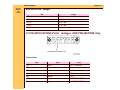
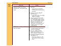
WIRE ASSEMBLIES
Important
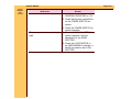
There are only 2 FUSES used in all Ektalite PROJECTORS. All FUSES are not available.
When installing a new FUSE, install the same type FUSE (amp) that was installed previously.
The color might vary among different PROJECTORS.
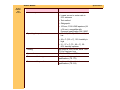
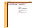
Table 1 WIRE ASSEMBLIES
Part No.
Description
From
3B1643
LINE
CAPACITOR
LINE
CAPACITOR
4B0376
4B0374
3B1644
FUSE-M7*
FUSE J1-4
DIODE/FUSE
MOTOR 7
MOTOR 11
MOTOR 8
4B0390
HARNESS
AF/TIMER
MOTOR 8
4B0390
HARNESS
AF/TIMER
MOTOR 12
*Use with BOARD ASSEMBLY 3B1999 only.
To
POWER INLET
Color, Amp, Size
BROWN or
BLUE across
POWER INLET
J105
GRAY, 0.5 A
J1
RED, 0.5 A
GRILL - a1
BLUE, 1.0 A,
LONG
FOCUS MOTOR BLUE
all wires and
FUSES
PHOTOCELL
BROWN
all wires and
FUSES
SERVICE MANUAL
23JUL01
SM5766-1
Page
6 of 96
Removals and Installations
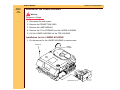
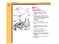
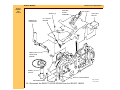
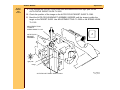
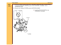
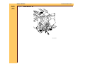
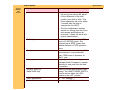
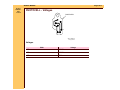
Removal for the LOWER HOUSING
Warning
Dangerous Voltage
1 Disconnect the main power.
2 Remove the PROJECTION LENS.
3 Remove the LAMP MODULE.
4 Remove the 6 Torx SCREWS from the LOWER HOUSING.
5 Pull the LOWER HOUSING off the TOP HOUSING.
Installation for the LOWER HOUSING
1 Do the removal for the LOWER HOUSING in reverse order.
SCREW (6)
LOWER
HOUSING
LAMP MODULE
A091_0001HCA
A091_0001HA
SERVICE MANUAL
23JUL01
SM5766-1
Page
7 of 96
Removals and Installations
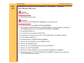
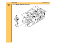
Removal for the FAN SHAFT ASSEMBLY
Warning
Dangerous Voltage
1 Disconnect the main power.
2 Do the removal for the LOWER HOUSING.
3 Lift the TRANSFORMER up.
4 Lift the POWER MODULE up.
5 Cut the 3 WIRE TIES:
• 1 on BLOWER COVER wires
• 2 on SMALL BOARD between the MOTOR and MECHANISM ASSEMBLY
6 Disconnect the 2 violet wires from the CYCLE SOLENOID on the SMALL BOARD.
7 Pull the SMALL BOARD up.
8 Remove the Torx SCREW from the BLOWER COVER ASSEMBLY.
9 Lift the GRILL ASSEMBLY in front of the BLOWER COVER ASSEMBLY up.
10 Loosen the Torx SCREW on the right track of the LOWER LIGHT BAFFLE ASSEMBLY
approximately half way.
11 Lift the LOWER LIGHT BAFFLE ASSEMBLY off the TAB on the BLOWER COVER
ASSEMBLY.
SERVICE MANUAL
23JUL01
SM5766-1
Page
8 of 96
Removals and Installations
TRANSFORMER
POWER MODULE
BLOWER COVER
WIRE TIE
WIRE TIE (2)
(not shown)
SCREW (not shown)
LOWER LIGHT
BAFFLE TAB
SCREW
GRILLE
ASSEMBLY
A091_4011HCA
A091_4011HA
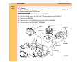
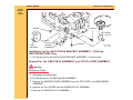
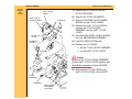
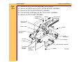
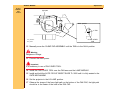
12 Remove the 2 long Torx SCREWS from the BLOWER COVER ASSEMBLY.
13 Lift the BLOWER COVER ASSEMBLY up.
14 Remove the 3 Torx SCREWS - 1/4 in. from the MOTOR.
15 Lift the MOTOR until you observe the FAN BELT and MECHANISM BELT.
16 Remove the FAN BELT and MECHANISM BELT off the MOTOR PULLEY. Use SPRING
HOOK TL-1165.
SERVICE MANUAL
23JUL01
SM5766-1
Page
9 of 96
Removals and Installations
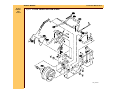
Caution
Move the MOTOR to allow access to the parts; wires are still connected to the MOTOR. Do
not cause damage to the MOTOR wires.
17 Remove the RETAINER CLIP from the FAN SHAFT.
18 Pull the FAN up and off the FAN SHAFT to allow access to the FAN BELT.
19 Remove the FAN BELT.
20 Remove the 3 Torx SCREWS from the FAN SHAFT ASSEMBLY.
21 Lift and remove the FAN SHAFT ASSEMBLY.
MOTOR
RETAINER CLIP
SCREW
SCREW (2)
FAN
FAN BELT
MECHANISM BELT
BLOWER
ASSEMBLY
SCREW (3)
FAN PLATE
ASSEMBLY
A091_4012HCA
A091_4012HA
SERVICE MANUAL
23JUL01
SM5766-1
Page
10 of 96
Removals and Installations
Installation for the FAN SHAFT ASSEMBLY
Important
When installing the FAN and MECHANISM BELTS, install the MECHANISM BELT on the
small MOTOR PULLEY, and the FAN BELT on the large MOTOR PULLEY.
1 Do the removal procedure for the FAN BELT and SHAFT in reverse order.
FAN BELT
MECHANISM BELT
A091_4015BCA
A091_4015BA
SERVICE MANUAL
23JUL01
SM5766-1
Page
11 of 96
Removals and Installations
Removal for the MOTOR
Warning
Dangerous Voltage
1 Disconnect the main power.
2 Do the removal for the LOWER HOUSING ASSEMBLY.
3 Lift the TRANSFORMER up.
4 Lift and remove the POWER MODULE.
5 Cut the 2 WIRE TIES on the SMALL BOARD between the MOTOR and MECHANISM
ASSEMBLY.
6 Disconnect the 2 violet wires from the CYCLE SOLENOID on the SMALL BOARD.
7 Pull the SMALL BOARD up.
8 Disconnect all wires on the MOTOR.
SERVICE MANUAL
23JUL01
SM5766-1
Page
12 of 96
Removals and Installations
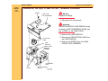
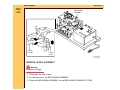
9 Remove 3 Hex SCREWS - 1/4 in. from the MOTOR.
10 Lift the MOTOR up to allow access to the FAN and MECHANISM BELTS.
11 Remove the FAN and MECHANISM BELTS from the MOTOR PULLEY.
12 Remove the MOTOR.
SCREW (3)
MOTOR
A091_4016GCA
A091_4016GA
SERVICE MANUAL
23JUL01
SM5766-1
Page
13 of 96
Removals and Installations
Installation for the MOTOR
Important
When installing the FAN and MECHANISM BELTS, install the MECHANISM BELT on the
small MOTOR PULLEY, and the FAN BELT on the large MOTOR PULLEY.
1 Do the removal for the MOTOR in reverse order.
FAN BELT
MECHANISM BELT
A091_4015BCA
A091_4015BA
Removal for the WORM PULLEY and MECHANISM BELT
Warning
Dangerous Voltage
1 Disconnect the main power.
2 Do the removal for the LOWER HOUSING ASSEMBLY.
3 Do the removal for the MOTOR except do not disconnect the wires from the MOTOR.
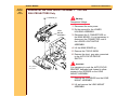
4 Remove the Torx SCREW from the WORM PULLEY ASSEMBLY.
SERVICE MANUAL
23JUL01
SM5766-1
Page
14 of 96
Removals and Installations
5 Move the TAB on the WORM PULLEY ASSEMBLY out.
6 Remove the WORM PULLEY ASSEMBLY and MECHANISM BELT.
WORM PULLEY
SCREW
MECHANISM
BELT
A091_4017GCA
A091_4017GA
Installation for the WORM PULLEY and MECHANISM BELT
Important
When installing the FAN and MECHANISM BELTS, install the MECHANISM BELT on the
small MOTOR PULLEY, and the FAN BELT on the large MOTOR PULLEY.
1 Do the removal for the WORM PULLEY and MECHANISM BELT in reverse order.
SERVICE MANUAL
Removals and Installations
23JUL01
SM5766-1
Page
15 of 96
FAN BELT
MECHANISM BELT
A091_4015BCA
A091_4015BA
Removal for the THERMAL FUSE ASSEMBLY
Warning
Dangerous Voltage
1 Disconnect the main power.
2 Do the removal for the LOWER HOUSING ASSEMBLY.
3 Disconnect the 3 CONNECTORS on the MAIN BOARD. It is not necessary to disconnect
the CONNECTOR next to the LOWER LIGHT BAFFLE ASSEMBLY.
4 Lift the MAIN BOARD up.
5 Cut and remove the necessary WIRE TIES.
6 Remove the brown wire from the THERMAL FUSE ASSEMBLY on the POWER SWITCH.
7 Remove the brown wire from the INTERLOCK SWITCH on the LOWER LIGHT BAFFLE.
8 Loosen the Torx SCREW on the PREHEAT DUCT approximately half way.
SERVICE MANUAL
23JUL01
SM5766-1
Page
16 of 96
Removals and Installations
9 Pull the THERMAL FUSE ASSEMBLY out of hole of the LOWER LIGHT BAFFLE
ASSEMBLY.
Installation for the THERMAL FUSE ASSEMBLY
1 Do the removal for the THERMAL FUSE ASSEMBLY in reverse order.
MAIN CIRCUIT BOARD
SCREW
PRE-HEAT
DUCT
INTERLOCK
SWITCH
(not shown)
POWER
SWITCH
THERMAL
FUSE
A091_4018GCA
A091_4018GA
SERVICE MANUAL
23JUL01
SM5766-1
Page
17 of 96
Removals and Installations
Removal for the LAMP MODULE RECEPTACLE
Warning
Dangerous Voltage
1 Disconnect the main power.
2 Do the removal for the LOWER HOUSING ASSEMBLY.
3 Disconnect the 3 CONNECTORS on the MAIN BOARD. It is not necessary to disconnect
the CONNECTORS next to the LOWER LIGHT BAFFLE ASSEMBLY.
4 Lift the MAIN BOARD up.
5 Cut and remove the necessary WIRE TIES.
6 Disconnect the blue wire from P102 and the white wire from P10 on the MAIN BOARD.
7 Remove the 2 Torx SCREWS on the left side of the LOWER LIGHT BAFFLE
ASSEMBLY.
8 Loosen the Torx SCREW on the right side of the LOWER LIGHT BAFFLE ASSEMBLY
approximately 1/2 way.
9 Lift and remove the LOWER LIGHT BAFFLE ASSEMBLY.
10 Lift the GRILL ASSEMBLY up.
11 Remove the 2 long Torx SCREWS from the BLOWER COVER ASSEMBLY.
12 Lift the BLOWER COVER ASSEMBLY up.
13 Lift and move the PREHEAT DUCT up.
SERVICE MANUAL
23JUL01
SM5766-1
Page
18 of 96
Removals and Installations
14 To remove the LAMP MODULE RECEPTACLE from the PREHEAT DUCT, compress the
2 TABS on the LAMP MODULE RECEPTACLE.
SCREW (2)
SCREW (2)
PRE-HEAT
DUCT
LOWER
LIGHT
BAFFLE
LAMP
MODULE
RECEPTACLE
BLOWER
COVER
ASSEMBLY
SCREW (not shown)
Installation for the LAMP MODULE RECEPTACLE
Warning
Dangerous Voltage
1 Disconnect the main power.
2 Do the removal for the LAMP MODULE RECEPTACLE in reverse order.
A091_4013HCA
A091_4013HA
SERVICE MANUAL
23JUL01
SM5766-1
Page
19 of 96
Removals and Installations
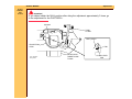
Removal for the CYCLE SOLENOID ASSEMBLY
Warning
SCREW (2)
Dangerous Voltage
1 Disconnect the main power.
2 Do the removals for the LOWER
HOUSING ASSEMBLY and the
MOTOR.
CYCLE
SOLENOID
3 Disconnect the 3 CONNECTORS on
the MAIN BOARD. It is not necessary to
disconnect the CONNECTORS next to
the LOWER LIGHT BAFFLE
ASSEMBLY.
CYCLE
SOLENOID
PLUNGER
4 Lift the MAIN BOARD up.
5 Cut and remove the necessary WIRE
TIES.
6 Disconnect the 2 violet wires from the
CYCLE SOLENOID on the SMALL
BOARD.
A091_4014GCA
A091_4014GA
7 Pull the SMALL BOARD up.
8 Remove the Torx SCREW from the
WORM PULLEY SHAFT.
9 Move the TAB on the WORM PULLEY
ASSEMBLY out of the MECHANISM
ASSEMBLY.
10 Lift and remove the WORM PULLEY
ASSEMBLY.
SERVICE MANUAL
23JUL01
SM5766-1
Page
20 of 96
Removals and Installations
11 Remove the 2 Hex SCREWS 1/4 in. from the 2 CYCLE SOLENOID GROMMETS.
12 Pull the CYCLE SOLENOID ASSEMBLY up and out.
13 If necessary, remove the CYCLE SOLENOID PLUNGER ASSEMBLY.
Installation for the CYCLE SOLENOID ASSEMBLY
Important
Do the adjustment for the CYCLE SOLENOID ASSEMBLY. See the Adjustments section.
1 Do the removal for the CYCLE SOLENOID ASSEMBLY in reverse order.
SERVICE MANUAL
23JUL01
SM5766-1
Page
21 of 96
Removals and Installations
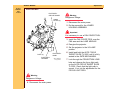
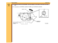
Removal for the MECHANISM ASSEMBLY
SCREW (3)
LENS
MOUNT
SCREW
DARK
SHUTTER
SWITCH
Warning
Dangerous Voltage
1 Disconnect the main power.
Important
MECHANISM
ASSEMBLY
The Models Style 2 1500 and 2000 have a
DARK SHUTTER SWITCH and AUTO
FOCUS SHUTTER DEFEAT SWITCH.
2 Do the removal for the LOWER
HOUSING ASSEMBLY.
3 Disconnect the 3 CONNECTORS on
the MAIN BOARD. It is not necessary to
disconnect the CONNECTORS next to
the LOWER LIGHT BAFFLE
ASSEMBLY.
SCREW
4 Lift the MAIN BOARD up.
5 Cut and remove the necessary WIRE
TIES.
6 Disconnect the 2 violet wires from the
CYCLE SOLENOID on the SMALL
BOARD.
FOCUS KNOB
7 Pull the SMALL BOARD up.
A091_4022CCA
A091_4022CA
AUTO FOCUS
DEFEAT SWITCH
(not shown)
SERVICE MANUAL
23JUL01
SM5766-1
Page
22 of 96
Removals and Installations
8 Disconnect all wires connected to the MECHANISM ASSEMBLY:
• 1 yellow wire from J105
• 1 orange wire from J105
• 1 green wire from POWER CORD
• 2 green ground wires from the lower MECHANISM ASSEMBLY
9 Remove the FOCUS KNOB from the FRONT PANEL.
Important
For the Models 1500 and 2000 only, disconnect the short, gray wire connected to the AUTOFOCUS DEFEAT SWITCH.
10 Remove the 3 Torx SCREWS from the LENS MOUNT ASSEMBLY.
11 Lift and move the LENS MOUNT ASSEMBLY up.
12 Do the removal for the MOTOR.
13 Remove the 3 Torx SCREWS from the MECHANISM ASSEMBLY.
14 Loosen the SCREW on the STABILIZER WALL approximately half way.
15 Models 1500 and 2000 Only: Remove the SCREW from the DARK SHUTTER SWITCH.
16 Remove the DARK SHUTTER SWITCH or DUAL SWITCH.
17 Remove the MECHANISM ASSEMBLY.
Installation for the MECHANISM ASSEMBLY
Important
To insert the SELECT BUTTON into the hole in the SELECT LEVER when installing the
MECHANISM ASSEMBLY, hold the SELECT BUTTON completely down.
1 Do the removal for the MECHANISM ASSEMBLY in reverse order.
SERVICE MANUAL
23JUL01
SM5766-1
Page
23 of 96
Removals and Installations
Removal for the AUTO-FOCUS BRACKET ASSEMBLY - 1500 and
2000 PROJECTORS Only
Warning
Dangerous Voltage
1 Disconnect the main power.
Important
There is no AUTO-FOCUS BRACKET ASSEMBLY for the Model 1000.
2 Do the removal for the LOWER HOUSING ASSEMBLY.
3 Disconnect the 3 CONNECTORS on the MAIN BOARD. It is not necessary to disconnect
the CONNECTORS next to the LOWER LIGHT BAFFLE ASSEMBLY.
4 Lift the MAIN BOARD up.
5 Cut and remove the necessary WIRE TIES.
6 Disconnect the 2 violet wires from the CYCLE SOLENOID on the SMALL BOARD.
7 Pull the SMALL BOARD up.
8 Do the removal for the MECHANISM ASSEMBLY.
9 Remove the Torx SCREW from the WORM PULLEY.
10 Remove the WORM PULLEY.
11 Remove the 2 Torx SCREWS from the CYCLE SOLENOID.
12 Remove the CYCLE SOLENOID.
13 Remove the Phillips SCREW from the AUTO-FOCUS BRACKET ASSEMBLY.
14 Pull and remove the AUTO-FOCUS BRACKET ASSEMBLY through the hole where the
CYCLE SOLENOID was located.
SERVICE MANUAL
Removals and Installations
23JUL01
SM5766-1
Page
24 of 96
SCREW
SCREW (2)
WORM
PULLEY
CYCLE
SOLENOID
AUTO
FOCUS
BRACKET
ASSEMBLY
SCREW
A091_4023BCA
A091_4023BA
Installation for the AUTO-FOCUS BRACKET ASSEMBLY - 1500 and
2000 PROJECTORS Only
1 Do the removal for the AUTO-FOCUS BRACKET ASSEMBLY in reverse order.
Removal for the CAM STACK ASSEMBLY and CYCLE LEVER ASSEMBLY
Warning
Dangerous Voltage
1 Disconnect the main power.
2 Do the removal for the MECHANISM ASSEMBLY.
3 Remove the INDEXER LEVER ASSEMBLY from the TOP PLATE of the MECHANISM
ASSEMBLY.
4 Remove the Torx SCREW from the WORM PULLEY ASSEMBLY.
5 Remove the WORM PULLEY ASSEMBLY.
SERVICE MANUAL
23JUL01
SM5766-1
Page
25 of 96
Removals and Installations
6 Remove the DIRECTION LEVER LINK from the DIRECTION LEVER.
7 Remove the DIRECTION LEVER SPRING from the DIRECTION LEVER.
8 Disconnect the LIFT LEVER SPRING from LIFT LEVER on the TOP PLATE of the
MECHANISM ASSEMBLY.
9 Remove the 7 Torx SCREWS from the TOP PLATE of the MECHANISM ASSEMBLY.
10 Remove the TOP PLATE.
11 Remove the LIGHT BAFFLE.
SERVICE MANUAL
Removals and Installations
23JUL01
SM5766-1
Page
26 of 96
SCREW (7)
DIRECTION
LEVER LINK
INDEXER
LEVER
ASSEMBLY
TOP PLATE
TOP LIGHT
BAFFLE
LIFT LEVER
SPRING
DIRECTION
LEVER LINK
SPRING
WORM
PULLEY
SELECT LEVER SPRING
RETARD SPRING
SCREW
12 Disconnect the SELECT LEVER SPRING from the SELECT LEVER.
A091_0011DCA
A091_0011DA
SERVICE MANUAL
23JUL01
SM5766-1
Page
27 of 96
Removals and Installations
13 Remove the NUT from the LIFT LEVER SHAFT.
14 Remove the LIFT LEVER and SHAFT.
15 Remove the 2 E-RINGS from the 2 CAM SHAFT BEARINGS.
16 Remove the 2 CAM SHAFT BEARINGS.
17 Press and hold the SELECT LEVER down.
18 Remove the CAM STACK ASSEMBLY.
LIFT
LEVER
LIFT LEVER SHAFT
SELECT LEVER
E-RING
SELECT LEVER
SPRING
BEARING
E-RING
NUT
CAM STACK
ASSEMBLY
TAB
BEARING
A091_0010HCA
A091_0010HA
SERVICE MANUAL
Removals and Installations
23JUL01
SM5766-1
Page
28 of 96
19 Remove the 2 SCREWS from the
CYCLE SOLENOID.
HALF-CYCLE
LEVER
20 Remove the CYCLE SOLENOID.
HALF-CYCLE
LEVER SPRING
E-RING (2)
21 Slide the PLUNGER and PLUNGER
SPRING off the CYCLE LEVER.
22 Remove the HALF CYCLE SPRING
between the CYCLE LEVER
ASSEMBLY and the HALF CYCLE
LEVER.
CYCLE
LEVER
23 Disconnect the INDEX LEVER SPRING
from the MECHANISM ASSEMBLY.
PLUNGER
SPRING
24 Push the INDEX LEVER back.
25 Remove the 2 E-RINGS:
• 1 on the CYCLE LEVER ASSEMBLY
PLUNGER
• 1 on the HALF CYCLE LEVER
Caution
Keep both the CYCLE LEVER ASSEMBLY
and the HALF CYCLE LEVER together and
observe the orientation of both LEVERS.
26 Slide both the CYCLE LEVER and
HALF CYCLE LEVER off the SHAFT.
CYCLE
SOLENOID
SCREW (2)
INDEX LEVER
and SPRING
(not shown)
A091_0009CCA
A091_0009CA
SERVICE MANUAL
23JUL01
SM5766-1
Page
29 of 96
Removals and Installations
Installation for the CAM STACK ASSEMBLY and CYCLE LEVER
ASSEMBLY
Caution
Keep both the CYCLE LEVER ASSEMBLY and the HALF CYCLE LEVER together and
observe the orientation of both LEVERS.
1 Do the removal for the CAM STACK ASSEMBLY and CYCLE LEVER ASSEMBLY in
reverse order.
SERVICE MANUAL
23JUL01
SM5766-1
Page
30 of 96
Removals and Installations
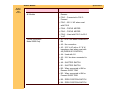
Removal for the Style 2 LAMP SOCKET TERMINAL ASSEMBLY
SCREW
LAMP DOOR
PLATE ASSEMBLY
Warning
Dangerous Voltage
1 Disconnect the main power.
Important
The EXTRA BRIGHT LAMP MODULE does
not have a HEAT ABSORBING GLASS and
has a LABEL on the LAMP DOOR.
2 Remove the LAMP MODULE.
PROJECTOR
LAMP
LAMP
EJECTOR
LAMP SOCKET
TERMINAL
ASSEMBLY
CONDENSER
LENS
TAB (2)
HEAT ABSORBING
GLASS
A091_0018CCA
A091_0018CA
3 Remove the PROJECTION LAMP from
the LAMP MODULE.
4 Remove the SCREW from the LAMP
DOOR PLATE ASSEMBLY.
SERVICE MANUAL
23JUL01
SM5766-1
Page
31 of 96
Removals and Installations
5 Remove the LAMP DOOR PLATE ASSEMBLY.
6 Release the 2 TABS on the bottom side of the LAMP MODULE next to the LAMP
MODULE DOOR.
Caution
Remove the CONDENSER LENS and HEAT ABSORBING GLASS and set the parts on a
clean cloth. Do not set on a cold surface; this will cause damage to the parts.
7 Remove the LAMP SOCKET TERMINAL ASSEMBLY.
8 Remove the LAMP EJECTOR.
Installation for the LAMP SOCKET TERMINAL ASSEMBLY
1 Do the removal for the LAMP SOCKET TERMINAL ASSEMBLY in reverse order.
SERVICE MANUAL
23JUL01
SM5766-1
Page
32 of 96
Removals and Installations
Removal for the LENS MOUNT ASSEMBLY - 1500 and
2000 PROJECTORS Only
SCREW (3)
Warning
Dangerous Voltage
1 Disconnect the main power.
LENS
MOUNT
ASSEMBLY
2 Do the removal for the LOWER
HOUSING ASSEMBLY.
3 Disconnect the 3 CONNECTORS on
the MAIN BOARD. It is not necessary to
disconnect the CONNECTOR next to
the LOWER LIGHT BAFFLE
ASSEMBLY.
4 Lift the MAIN BOARD up.
5 Remove the FOCUS KNOB.
6 Remove the short, gray wire connected
to the AUTO-FOCUS DEFEAT
SWITCH.
Important
A091_4024GCA
A091_4024GA
It is necessary to push the AUTO-FOCUS
BRACKET backward and forward to allow
access to the SCREWS on the LENS
MOUNT ASSEMBLY.
7 Remove the 3 SCREWS from the LENS
MOUNT ASSEMBLY.
8 Lift and remove the LENS MOUNT
ASSEMBLY.
SERVICE MANUAL
23JUL01
SM5766-1
Page
33 of 96
Removals and Installations
Installation for the LENS MOUNT ASSEMBLY - 1500 and
2000 PROJECTORS Only
1 Do the removal for the LENS MOUNT ASSEMBLY in reverse order.
Removal for the LENS MOUNT ASSEMBLY - 500 and
1000 PROJECTORS Only
SCREW (3)
Warning
Dangerous Voltage
1 Disconnect the main power.
LENS
MOUNT
ASSEMBLY
2 Do the removal for the LOWER
HOUSING ASSEMBLY.
3 Disconnect the 3 CONNECTORS on
the MAIN BOARD. It is not necessary to
disconnect the CONNECTOR next to
the LOWER LIGHT BAFFLE
ASSEMBLY.
4 Lift the MAIN BOARD up.
5 Remove the FOCUS KNOB.
6 Remove the 3 SCREWS from the LENS
MOUNT ASSEMBLY.
7 Lift and remove the LENS MOUNT
ASSEMBLY.
A091_0005GCA
A091_0005GA
SERVICE MANUAL
23JUL01
SM5766-1
Page
34 of 96
Removals and Installations
Installation for the LENS MOUNT ASSEMBLY - 500 and
1000 PROJECTORS Only
1 Do the removal for the LENS MOUNT ASSEMBLY in reverse order.
Removal for the AUTO-FOCUS SWITCH ASSEMBLY - Models 1500 and
2000 PROJECTORS Only
AUTO FOCUS
MOTOR BRACKET
Warning
Dangerous Voltage
1 Disconnect the main power.
Important
There is no AUTO-FOCUS SWITCH
ASSEMBLY on the Models 500 and 1000.
2 Do the removal for the LOWER
HOUSING ASSEMBLY.
LOCKING
TAB
AUTO FOCUS
SWITCH LEVER
AUTO FOCUS SWITCH ASSEMBLY
3 Disconnect the 3 CONNECTORS on
the MAIN BOARD. It is not necessary to
disconnect the CONNECTOR next to
the LOWER LIGHT BAFFLE
ASSEMBLY.
grey, red,
and black
wires
A091_4028GCA
A091_4028GA
4 Lift the MAIN BOARD up.
5 Remove the FOCUS KNOB.
6 Remove the short, gray wire from the
AUTO-FOCUS DEFEAT SWITCH.
SERVICE MANUAL
23JUL01
SM5766-1
Page
35 of 96
Removals and Installations
Important
It is necessary to push the AUTO-FOCUS BRACKET backward and forward to allow access
to the SCREWS on the LENS MOUNT ASSEMBLY.
7 Remove the 3 SCREWS from the LENS MOUNT ASSEMBLY.
8 Lift and remove the LENS MOUNT ASSEMBLY.
9 Remove the gray, red, and black wires from the AUTO FOCUS SWITCH ASSEMBLY.
Important
Keep the AUTO-FOCUS SWITCH LEVER that is connected to the AUTO FOCUS SWITCH
so you can install it on the new AUTO FOCUS SWITCH.
10 To disconnect and remove the AUTO FOCUS SWITCH, bend the LOCKING TAB on the
FOCUS MOTOR BRACKET until it is aligned with the hole in the AUTO FOCUS
SWITCH.
Installation for the AUTO-FOCUS SWITCH ASSEMBLY - Models 500 and
2000 PROJECTORS Only
Important
Align the 2 TABS on the AUTO-FOCUS SWITCH with the FOCUS MOTOR BRACKET,
checking that the end of the AUTO-FOCUS LEVER engages with the CYCLE SOLENOID
PLUNGER. After the AUTO-FOCUS SWITCH is in the correct position, bend the LOCKING
TAB to hold the AUTO FOCUS SWITCH in place.
1 Do the removal for the AUTO-FOCUS SWITCH in reverse order.
SERVICE MANUAL
23JUL01
SM5766-1
Page
36 of 96
Removals and Installations
Removal for the FOCUS SHAFT ASSEMBLY - 1500 and
2000 PROJECTORS Only
Warning
Dangerous Voltage
1 Disconnect the main power.
2 Do the removal for the LOWER HOUSING ASSEMBLY.
3 Disconnect the 3 CONNECTORS on the MAIN BOARD. It is not necessary to disconnect
the CONNECTOR next to the LOWER LIGHT BAFFLE ASSEMBLY.
4 Lift the MAIN BOARD up.
5 Remove the FOCUS KNOB.
6 Remove the short, gray wire from the AUTO-FOCUS DEFEAT SWITCH.
Important
It is necessary to push the AUTO-FOCUS BRACKET backward and forward to allow access
to the SCREWS on the LENS MOUNT ASSEMBLY.
7 Remove the 3 SCREWS from the LENS MOUNT ASSEMBLY.
8 Lift and remove the LENS MOUNT ASSEMBLY.
9 Remove the FOCUS SHAFT SPRING from the LENS MOUNT BRACKET.
10 Remove the SPRING from the CLAMP LEVER on the LENS MOUNT BRACKET.
11 Remove the SPRING from the PHOTOCELL BRACKET.
12 Remove the E-RING and SPACER from the FOCUS SHAFT ASSEMBLY.
13 Remove the SCREW from the LENS SUPPORT BRACKET.
14 Lift and remove the LENS SUPPORT BRACKET.
15 Remove the AUTO-FOCUS SWITCH ASSEMBLY.
16 Remove the SCREW from the RACK SOLENOID ASSEMBLY.
SERVICE MANUAL
23JUL01
SM5766-1
Page
37 of 96
Removals and Installations
17 Remove the RACK SOLENOID ASSEMBLY and PLUNGER.
18 Remove the SCREW from the FOCUS MOTOR BRACKET ASSEMBLY.
19 Remove the FOCUS MOTOR BRACKET ASSEMBLY.
20 Push the RACK LEVER away from the FOCUS SHAFT ASSEMBLY.
21 Remove the FOCUS SHAFT ASSEMBLY.
CLAMP LEVER
SPRING
SCREW
FOCUS SHAFT
SPRING
RACK LEVER
(not shown)
FOCUS SHAFT
SCREW
FOCUS MOTOR
BRACKET
RACK
SOLENOID
SPACER
PLUNGER
E-RING
LENS SUPPORT BRACKET
PHOTOCELL
AUTO-FOCUS
BRACKET
SWITCH
SPRING
ASSEMBLY
SCREW
A091_4029HCA
A091_4029HA
SERVICE MANUAL
23JUL01
SM5766-1
Page
38 of 96
Removals and Installations
Installation for the FOCUS SHAFT ASSEMBLY - 1500 and
2000 PROJECTORS Only
Important
Do the adjustments for the PHOTOCELL NULL and AUTO-FOCUS CLAMP after installation.
See the Adjustments section.
Removal for the FOCUS SHAFT ASSEMBLY - 500 and
1000 PROJECTORS Only
Warning
Dangerous Voltage
1 Disconnect the main power.
2 Do the removal for the LOWER HOUSING ASSEMBLY.
3 Disconnect the 3 CONNECTORS on the MAIN BOARD. It is not necessary to disconnect
the CONNECTOR next to the LOWER LIGHT BAFFLE ASSEMBLY.
4 Lift the MAIN BOARD up.
5 Remove the FOCUS KNOB.
6 Remove the 3 SCREWS from the LENS MOUNT ASSEMBLY.
7 Lift and remove the LENS MOUNT ASSEMBLY.
8 Remove the FOCUS SHAFT SPRING from the LENS MOUNT BRACKET.
9 Remove the E-RING and SPACER from the FOCUS SHAFT ASSEMBLY.
10 Remove the SCREW from the LENS SUPPORT BRACKET.
11 Lift and remove the LENS SUPPORT BRACKET.
12 Remove the E-RING and SPACER from the FOCUS SHAFT ASSEMBLY.
13 Remove the SCREW from the FOCUS MOTOR BRACKET ASSEMBLY.
14 Remove the FOCUS MOTOR BRACKET ASSEMBLY.
SERVICE MANUAL
23JUL01
SM5766-1
Page
39 of 96
Removals and Installations
15 Remove the FOCUS SHAFT ASSEMBLY.
SCREW
FOCUS SHAFT
ASSEMBLY
FOCUS SHAFT
SPRING
FOCUS MOTOR
BRACKET
SPACER
LENS SUPPORT
BRACKET
E-RING
SCREW
Installation for the FOCUS SHAFT ASSEMBLY - 500 and
1000 PROJECTORS Only
1 Do the removal for the FOCUS SHAFT ASSEMBLY in reverse order.
A091_0020HCA
A091_0020HA
SERVICE MANUAL
23JUL01
SM5766-1
Page
40 of 96
Adjustments
Section 2: Adjustments
CYCLE SOLENOID
Warning
Dangerous Voltage
1 Connect the main power.
Important
• The CYCLE SOLENOID must operate correctly to do this adjustment.
• The MECHANISM ASSEMBLY does not have to be removed to do this adjustment.
2 Do the removal for the LOWER HOUSING ASSEMBLY.
3 Bend the CYCLE LEVER up or down. Use T-BAR TL-3003.
4 Rotate the projector up.
5 Press the “FORWARD” BUTTON to check for correct operation.
6 Press the “REVERSE” BUTTON to check for correct operation.
7 Do the steps above until the FORWARD and REVERSE functions operates correctly.
SERVICE MANUAL
Adjustments
23JUL01
SM5766-1
Page
41 of 96
MECHANISM
ASSEMBLY
T-BAR
TL-3003
CYCLE
BAR
A091_0007HCA
A091_0007HA
INDEXER LEVER ASSEMBLY
Warning
Dangerous Voltage
1 Disconnect the main power.
2 Do the removal for the MECHANISM ASSEMBLY.
3 Place the MECHANISM ASSEMBLY on the MECHANISM RUNNING FIXTURE.
SERVICE MANUAL
23JUL01
SM5766-1
Page
42 of 96
Adjustments
4 Check the alignment of the INDEXER LEVER with the hole in the TOP PLATE
ASSEMBLY at Position 1.
5 Bend the INDEXER LEVER to the correct position.
6 Check the travel of the INDEXER LEVER in the FORWARD position. When the
INDEXER LEVER moves in the FORWARD position, the gate edge of the black plastic
should be between the 2 holes at Position 2.
7 Bend the INDEXER LEVER until you reach the correct position.
MECHANISM
ASSEMBLY
TOP PLATE
Bend
here.
MECHANISM
RUNNING FIXTURE
position 1
position 2
A091_0008HCA
A091_0008HA
SERVICE MANUAL
23JUL01
SM5766-1
Page
43 of 96
Adjustments
SLIDE LIFT LEVER MANUAL
Warning
Dangerous Voltage
1 Disconnect the main power.
2 Do the removal for the MECHANISM ASSEMBLY.
3 Place the MECHANISM ASSEMBLY on the MECHANISM RUNNING FIXTURE.
4 Press and hold the SELECT LEVER down to move the SLIDE LIFT LEVER to the
highest position.
5 Measure the height of the SLIDE LIFT LEVER. Use SLIDE LIFT LEVER GAUGE TL3001. The SLIDE LIFT LEVER should make contact with the low surface of the SLIDE
LIFT LEVER GAUGE TL-3001; the SLIDE LIFT LEVER should not make contact with the
high surface of the SLIDE LIFT LEVER GAUGE TL-3001.
6 Bend the SLIDE LIFT LEVER until the adjustment is correct.
SLIDE LIFT
LEVER GUAGE
TL-3001
SLIDE LIFT
LEVER
SELECT
LEVER
(not shown)
A091_0016BCA
A091_0016BA
SERVICE MANUAL
23JUL01
SM5766-1
Page
44 of 96
Adjustments
SLIDE LIFT LEVER POWER
Warning
Dangerous Voltage
1 Disconnect the main power.
2 Do the removal for the MECHANISM ASSEMBLY.
3 Place the MECHANISM ASSEMBLY on the MECHANISM RUNNING FIXTURE TL-3000.
4 Energize the MECHANISM FIXTURE.
5 Press and hold the SELECT LEVER down to move the SLIDE LIFT LEVER to the
highest position.
6 Measure the height of the SLIDE LIFT LEVER. Use SLIDE LIFT LEVER GAUGE TL3001. The SLIDE LIFT LEVER should make contact with the low surface of the SLIDE
LIFT LEVER GAUGE TL-3001; the SLIDE LIFT LEVER should not make contact with the
high surface of the SLIDE LIFT LEVER GAUGE TL-3001.
7 Bend the SLIDE LIFT LEVER until the adjustment is correct.
SLIDE LIFT
LEVER GUAGE
TL-3001
SLIDE LIFT
LEVER
SELECT
LEVER
(not shown)
A091_0016BCA
A091_0016BA
SERVICE MANUAL
23JUL01
SM5766-1
Page
45 of 96
Adjustments
ZERO POSITION SWITCH - 2000 PROJECTOR Only
a
Important
6
5
4
3
2
1
b
It is necessary use make a 5/16 in.
WRENCH to do this adjustment.
1 Energize the projector.
12-PIN APPLICATION PLUG
A091_4021ACA
A091_4021AA
2 Connect the DIGITAL VOLT METER
(DVM) between PINS B5 and B6 of the
12 PIN APPLICATIONS PLUG.
3 With no TRAY installed, the DVM
should measure •.
4 Install a TRAY.
5 To move the TRAY out of the zero
position, press the “FORWARD” or
“REVERSE” BUTTONS; the DVM
should measure 0 W.
SERVICE MANUAL
23JUL01
SM5766-1
Page
46 of 96
Adjustments
ZERO POSITION
SWITCH
NUT
6 If the measurements are not within
specification, adjust the ZERO
POSITION SWITCH ECCENTRIC to
specification.
A091_0017GCA
A091_0017GA
Focus Light Path - 1500 and 2000 PROJECTORS Only
Warning
Dangerous Voltage
1 Disconnect the main power.
2 Remove the PROJECTION LENS.
3 Do the removal for the LOWER HOUSING ASSEMBLY.
SERVICE MANUAL
23JUL01
SM5766-1
Page
47 of 96
Adjustments
4 Disconnect the MAIN BOARD from the 4 POSTS to allow access to the FOCUS LIGHT
PATH.
Important
It is necessary to make a FAN COVER TOOL. See the Tools section.
5 Install the FAN COVER TOOL over the FAN area and the LAMP MODULE.
6 Energize the projector.
7 Set the projector to the LOW LAMP position.
8 Install the AUTO-FOCUS TARGET SLIDE TL-3002 until it is fully seated in the GATE
MECHANISM.
SERVICE MANUAL
23JUL01
SM5766-1
Page
48 of 96
Adjustments
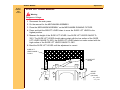
9 Look through the PROJECTION LENS hole and observe the focus light path on the
AUTO-FOCUS TARGET SLIDE TL-3002.
10 Check the position of the image on the AUTO-FOCUS TARGET SLIDE TL-3002.
11 Bend the AUTO-FOCUS BRACKET ASSEMBLY MIRROR until the image is within the
target on the TARGET SLIDE. Use ADJUSTMENT TOOL TL-3005 or the SPRING HOOK
TL-1165.
ADJUSTMENT TOOL
TL-3005 or
SPRING HOOK TL-1165
AUTO FOCUS
BRACKET
ASSEMBLY
light path
image
AUTO-FOCUS TARGET SLIDE TL-3002
A091_4026HCA
A091_4026HA
SERVICE MANUAL
23JUL01
SM5766-1
Page
49 of 96
Adjustments
NULL
Warning
Dangerous Voltage
1 Disconnect the main power.
2 Do the removal for the LOWER HOUSING ASSEMBLY.
Important
It is necessary to use a FAN COVER TOOL.
3 Install the FAN COVER TOOL over the FAN area and the LAMP MODULE.
4 Energize the projector.
5 Set the projector to the LO-LAMP position.
6 Install and hold the AUTO FOCUS TARGET SLIDE TL-3002 until it is fully seated in the
GATE MECHANISM.
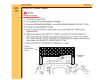
7 Look through the PROJECTION LENS hole and observe the focus light path on the
AUTO-FOCUS TARGET SLIDE TL-3002. Check that the light image is correct. If not, do
the adjustment for the FOCUS LIGHT PATH.
8 Check that the TAB on the CLAMP PAD ASSEMBLY is in the NULL position. If the TAB
is not in the correct position, do the adjustment for the NULL.
9 Bend the PHOTOCELL BRACKET to move the NULL in the center; use T-BAR TL-3003.
SERVICE MANUAL
23JUL01
SM5766-1
Page
50 of 96
Adjustments
Important
If you cannot obtain the NULL position after doing the adjustment approximately 3 times, go
to the adjustment for the PHOTOCELL.
light path
T-BAR
TL-3003
NULL position
PROJECTION
LENS
A091_4031BCA
A091_4031BA
TAB
AUTO-FOCUS
TARGET SLIDE
TL-3002
CLAMP LEVER
PAD
SERVICE MANUAL
23JUL01
SM5766-1
Page
51 of 96
Adjustments
PHOTOCELL
PHOTOCELL
CIRCUIT BOARD
wratten
FILTER (2)
Warning
Dangerous Voltage
1 Disconnect the main power.
2 Do the removal for the LOWER
HOUSING ASSEMBLY.
Important
It is necessary to use a FAN COVER TOOL.
3 Install the FAN COVER TOOL over the
FAN area and the LAMP MODULE.
4 Energize the projector.
5 Set the projector to the LO-LAMP
position.
POST (2)
PHOTOCELL
HOUSING
Warning
Dangerous Voltage
8 Disconnect the main power.
PHOTOCELL
MASK
A091_4032GCA
A091_4032GA
6 Install and hold the AUTO FOCUS
TARGET SLIDE TL-3002 until it is fully
seated in the GATE MECHANISM.
7 Look through the PROJECTION LENS
hole and observe the focus light path
on the AUTO-FOCUS TARGET SLIDE
TL-3002. Check that the light path is
correct. If not, do the adjustment for the
FOCUS LIGHT PATH.
SERVICE MANUAL
23JUL01
SM5766-1
Page
52 of 96
Adjustments
9 Heat the 2 POSTS on the PHOTOCELL HOUSING to allow the POSTS to bend enough
to pull the PHOTOCELL BOARD up and off the PHOTOCELL HOUSING. Use a
SOLDERING IRON.
10 Remove the 2 Wratten FILTERS and the PHOTOCELL MASK.
hole
11 Install the FAN CAP 232729 in the
PHOTOCELL HOUSING.
FAN CAP
FAN CAP
light image
A091_4033GCA
A091_4033GA
SERVICE MANUAL
23JUL01
SM5766-1
Page
53 of 96
Adjustments
light path
NULL position
TAB
A091_4027BCA
A091_4027BA
CLAMP LEVER
PAD
12 Manually move the CLAMP PAD ASSEMBLY until the TAB is in the NULL position.
Warning
Dangerous Voltage
13 Connect the main power.
Important
It is necessary to use a FAN COVER TOOL.
14 Install the FAN COVER TOOL over the FAN area and the LAMP MODULE.
15 Install and hold the AUTO FOCUS TARGET SLIDE TL-3002 until it is fully seated in the
GATE MECHANISM.
16 Set the projector to the LO-LAMP position.
17 Observe the image of the focus light path on the bottom of the FAN CAP; the light path
should be in the center of the hole in the FAN CAP.
SERVICE MANUAL
23JUL01
SM5766-1
Page
54 of 96
Adjustments
18 Bend the CLAMP PAD ASSEMBLY until the image is in the center of the hole in the FAN
CAP.
19 Assemble the PHOTOCELL MASK, FILTERS and PHOTOCELL BOARD.
hole
T-BAR TL-3003
FAN CAP
AUTO-FOCUS
TARGET SLIDE
TL-3002
light image
CLAMP PAD
ASSEMBLY
A091_4030BCA
A091_4030BA
SERVICE MANUAL
23JUL01
SM5766-1
Page
55 of 96
Adjustments
CLAMP PAD ASSEMBLY - 1500 and 2000 PROJECTORS Only
Warning
Dangerous Voltage
1 Disconnect the main power.
2 Do the removal for the LOWER
HOUSING ASSEMBLY.
Important
SCREW
It is necessary to use a FAN COVER TOOL.
NUT
3 Install the FAN COVER TOOL over the
FAN area and the LAMP MODULE.
4 Connect the REMOTE CONTROL
ASSEMBLY to the REMOTE
RECEPTACLE.
CLAMP PAD
ASSEMBLY
A091_4041GCA
A091_4041GA
SERVICE MANUAL
23JUL01
SM5766-1
Page
56 of 96
Adjustments
Warning
Dangerous Voltage
5 Connect the main power.
6 Loosen the NUT on the CLAMP PAD ASSEMBLY.
7 Energize the REMOTE FOCUS in either direction.
8 Rotate the SCREW on the CLAMP PAD ASSEMBLY to adjust the pressure of the
REMOTE FOCUS CLAMP on the CLAMP PAD ASSEMBLY until the CLAMP PAD
ASSEMBLY does not move.
9 Release the REMOTE FOCUS.
10 Tighten the NUT on the CLAMP PAD ASSEMBLY.
11 Install the AUTO-FOCUS GAUGE TL-1744 in the MECHANISM GATE. The CLAMP PAD
ASSEMBLY should move forward and backward using TL-1744. If not, adjust the
SCREW on the CLAMP PAD ASSEMBLY again; the CLAMP PAD ASSEMBLY adjustment
is too tight and not correct.
SERVICE MANUAL
23JUL01
SM5766-1
Page
57 of 96
Adjustments
DARK SHUTTER
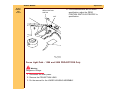
1 Do the removal for the LOWER HOUSING.
2 Insert a thin SLIDE into the GATE MECHANISM; the DARK SHUTTER should open.
3 Check the PRESSURE PAD is correctly aligned with the DARK SHUTTER.
4 Bend the PRESSURE PAD to adjust the alignment.
DARK
SHUTTER
PRESSURE
PAD
A091_0013GCA
A091_0013GA
SERVICE MANUAL
23JUL01
SM5766-1
Page
58 of 96
Preventive Maintenance
Section 3: Preventive Maintenance
1 Apply SUPER LUBE TL-4276 to the following parts and areas of the PROJECTOR; see
the illustrations.
• FAN
• INDEXER LEVER and TOP PLATE
• WORM PULLEY ASSEMBLY
• CAM STACK ASSEMBLY
• CYCLE LEVERS
• PIVOT SHAFT and LEVERS
• LENS MOUNT ASSEMBLY
SERVICE MANUAL
23JUL01
SM5766-1
Page
59 of 96
Figure 1
Preventive Maintenance
LENS MOUNT AY
A091_4037GA
SERVICE MANUAL
23JUL01
SM5766-1
Page
60 of 96
Figure 2
Preventive Maintenance
FAN AY
A091_0021GA
SERVICE MANUAL
23JUL01
SM5766-1
Page
61 of 96
Figure 3
Preventive Maintenance
INDEXER LEVER and TOP PLATE
A091_0023HA
SERVICE MANUAL
23JUL01
SM5766-1
Page
62 of 96
Figure 4
Preventive Maintenance
CYCLE LEVER and CAM STACK
A091_0022DA
SERVICE MANUAL
23JUL01
SM5766-1
Page
63 of 96
Special Tools
Section 4: Special Tools
Tool No.
TL-1744
TL-2264
TL-2265
TL-3002
TL-3003
TL-3005
TL-3255
TL-4276
Description
AUTO-FOCUS GAUGE
FOCUS TEST (flat field)
DIELECTRIC TESTER (optional)
AUTO-FOCUS TARGET SLIDE
ADJUSTMENT T-BAR
ADJUSTMENT TOOL
Torx DRIVER SET
SUPER LUBE
DIGITAL MULTIMETER
SERVICE MANUAL
23JUL01
SM5766-1
Page
64 of 96
Special Tools
Important
The LOWER HOUSING ASSEMBLY is a part of the cooling function.
1 To operate the projector with the LOWER HOUSING removed,
make a FAN COVER TOOL.
Cut here.
FAN
COVER
TOOL
11.5 cm
(4.5 in.)
A091_0024GCA
A091_0024GA
SERVICE MANUAL
23JUL01
SM5766-1
Page
65 of 96
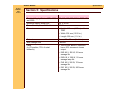
Specifications
Section 5: Specifications
Electrical Supply, Modes 1000, 1500,
and 2000
Electrical Supply, Model 500
Power Consumption, All Models
Dimensions
100, 115, 130, 220, 240 V, 50/60 HZ
230 V, 50 HZ
400 W
• Height: 119 mm (4.69 in.) without
TRAY
• Width: 238 mm (12.93 in.)
Slide size
Slide change time
Lamp
(in LO position, 70% of rated
brilliance)
• Length: 295 mm (11.6 in.)
35 mm, 50 x 50 mm (2 x 2 in.)
1 second
• The EXTRA BRIGHT MODULE
has a 30% increase in lumen
output.
• EXR 82 V, 300 W, 35 hours
average life
• EXW 82 V, 300 W, 15 hours
average lamp life
• FHS 82 V, 300 W, 70 hours
average life
• EXY 82 V, 300 W, 200 hours
average life
SERVICE MANUAL
23JUL01
SM5766-1
Page
66 of 96
Lumen Output
Specifications
• 900 minimum with EXR lamp
• Lowest corner to center ratio is
55% minimum
• Test method
• Ektagraphic
Operating temperature
• 102 mm, F/2.8 LENS aperture (24
x 36 mm), compatible with
European specification DIN 19027
• 4.5 × C (40 × F), 15% humidity in
low
• 49 × C (120 × F), 15% humidity in
high
Cooling
Approvals
Environmental storage
Environmental operation
• 21 - 27 × C (70 - 80 × F), 20 60% humidity optimum
Fan speed is 3000 RPMs, emits 1360
BTUs of heat per hour
TUV, UL, VDE, and CSA
Complies with storage test
specifications (TS 172)
Complies with climactic test
specifications (TS 218)
SERVICE MANUAL
23JUL01
SM5766-1
Page
67 of 96
Safety
Specifications
• 3 GROUNDED POWER CORDS,
detachable
• Heat sensitive interrupt fuses
• 117 C ° LAMP THERMAL FUSE
• 169 C ° MOTOR THERMAL
FUSE
• 150 C ° TRANSFORMER
Dielectric strength
Automatic Timer
• SAFETY INTERLOCK SWITCH,
deenergizes projector when the
LAMP MODULE is removed.
Apply 1200 V, 50 Hz for 1 second;
maximum leakage current is 2.5 mA.
Models 1500 and 2000 Only:
• Operates between the following
times:
– Fast = 3 ± 1 second
Elevation
– Slow = 22 ± 6 seconds
16 ° maximum front elevation
assembly.
SERVICE MANUAL
23JUL01
SM5766-1
Page
68 of 96
Auto Focus System
Reliability
Maintenance
Warranty
INT/EXT SWITCH
Model 2000 Only
Gate Temperature
Noise Development
Specifications
• After the initial focus adjustment,
the auto-focus system will adjust
for the difference in the slide
position from slide to slide. This
focus adjustment will occur within
1 second after the slide is
inserted into the GATE.
• The focus adjustment variation
should not change from the focus
and reverse specifications by
more than 3 times the focus and
reverse specifications.
The projector can operate for 2000
hours or 2,000,000 cycles. The
projector has a MTBF (mean time
between failures) of 7500 operation
hours.
Preventive maintenance by a qualified
service person is recommended
every 1500 hours of operation, or
after 1 year.
The projector has a warranty by
Eastman Kodak Company to operate
correctly for one year from the date
of purchase.
Used for internal and external LAMP
control. The LAMP POWER SWITCH
must be set on either the LO/HI
position in the “INT” position.
95 - 100° average
Approximately 50 dB
SERVICE MANUAL
23JUL01
SM5766-1
Page
69 of 96
6-PIN REMOTE CONTROL
All Models
Specifications
• PIN 1 - Connected to PIN 3 =
Reverse
• PIN 2 - Connected to PIN 3 Forward
• PIN 3 - 25.5 V AC when used
with PIN 6
• PIN 4 - FOCUS MOTOR
• PIN 5 - FOCUS MOTOR
12-PIN DISSOLVE
Model 2000 Only
• PIN 6 - Used with PIN 3 for 25.5
V AC
• A1 - 25.5 V ac when connected to
B4
• A2 - No connection
• A3 - 25.5 V AC with a 2.7 K W
impedance load when used with
A4 (DISSOLVE CONTROL)
• A4 - Used with A3
• A5 - 24 V dc when connected to
B4
• A6 - SHUTTER SWITCH
• B1 - SHUTTER SWITCH
• B2 - When connected to B4 for
Reverse SLIDE TRAY
• B3 - When connected to B4 for
Forward SLIDE TRAY
• B5 - ZERO POSITION SWITCH
• B6 - ZERO POSITION SWITCH
SERVICE MANUAL
23JUL01
SM5766-1
Page
70 of 96
Diagnostics
Section 6: Diagnostics
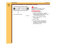
MAIN MOTOR - Voltages
84.2 V
1.6
12
11
brown
10
white
9
8
black
7
LAMP VOLTAGE is
74 V AC
between brown
and white for
LONG LIFE MODELS
117 V AC
6.1
MOTOR
A091_0006BCA
A091_0006BA
MAIN MOTOR PIN - Colors
PIN
12
11
10
9
8
7
Color
blue
red
black
yellow
blue
green
SERVICE MANUAL
23JUL01
SM5766-1
Page
71 of 96
Diagnostics
MAIN MOTOR PIN - Voltages
PIN
Voltage
7-9
8-9
10-11
11-12
10-12
50 V ac
25.5 V ac
14.5 V ac
14.5 V ac
29 V ac
12-PIN APPLICATIONS PLUG - Voltages, 2000 PROJECTORS Only
a
6
5
4
3
2
1
b
12-PIN APPLICATION PLUG
A091_4021ACA
A091_4021AA
Connections
PIN
A1
A2
A3
A4
A5
A6
B1
Color
blue
---white
yellow
green
gray
gray
From
PIN 8 - MOTOR
---J105
J104
J105
SHUTTER SWITCH
SHUTTER SWITCH
SERVICE MANUAL
23JUL01
SM5766-1
Page
72 of 96
Diagnostics
PIN
Color
B2
B3
B4
B5
orange
yellow
yellow
violet
B6
violet
From
J104
J105
J104
ZERO POSITION
SWITCH
ZERO POSITION
SWITCH
Voltages
PINS
A1
A3
A5
A6
B5
to
to
to
to
to
B4
A4
B4
B1
B6
B4 to B2
B4 to B3
Description
AC POWER SUPPLY
DISSOLVE CONTROL
DC POWER SUPPLY
SHUTTER SWITCH
ZERO POSITION
SWITCH
Reverse
Forward
Voltage
25.5 V ac, 500 mA
25.5 V ac
20.0 V dc, 500 mA
25.5 V ac
25.5 V ac
SERVICE MANUAL
23JUL01
SM5766-1
Page
73 of 96
Diagnostics
PHOTOCELL - Voltages
PHOTOCELL
3
1
2
A091_4036ACA
A091_4036AA
Voltages
PINS
1-2
2-3
1-3
Voltage
14.5 V ac
14.5 V ac
29 V ac
SERVICE MANUAL
23JUL01
SM5766-1
Page
74 of 96
Diagnostics
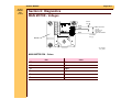
6-PIN REMOTE PLUG - Voltages
REV
S1
CABLE
CONNECTOR
FWD
1 6 5
2
4
3
S2
GRAY
GREEN
BLUE
2.7 K
R1
2
RED
LED
FOCUS
BLACK
1 3
5
S3
4 6
YELLOW
25.5 VOLTS AC
A091_0001BA_
Voltages
PIN
1
2
3
4
5
6
Description
Reverse
Forward
Common - 25.5 V ac
Focus - Forward
Focus - Reverse
RACK SOLENOID
SERVICE MANUAL
23JUL01
SM5766-1
Page
75 of 96
Diagnostics
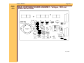
SMALL COMPONENT BOARD ASSEMBLY - Voltages, 1500 and
2000 PROJECTORS
WWK R A V V O B Y B
RY
GN
R W
W
J1
J2
R3
CR5
CR3
CR4
F1
CR2
R7
C5
Q1
Q2
R6
R4
C1
R17
R5
SLIDE PROJECTOR BOARD
Q3
C4
CR1
+
C3
R12
R11
R10
+
R13
R14
CR6
R15
C2
Q4
A091_4034DC
SERVICE MANUAL
23JUL01
SM5766-1
Page
76 of 96
Diagnostics
Table 2 SMALL COMPONENT BOARD ASSEMBLY - Voltages, 1500 and
2000 PROJECTORS
Description
Component
Color - +
TIMER Circuit
CR3
TIMER Circuit
TIMER Circuit
TIMER Circuit
TIMER Circuit
CYCLE HOLD
DOWN LEVERS
CYCLE HOLD
DOWN LEVERS
FOCUS
FOCUS
FOCUS
FOCUS
Q3
Q3
Q4
Q4
CR4
Red (+) and Black
(-)
Black, G (-)
Red, A (+)
Black, G (-)
Red, K (+)
Red (+)
CR4
Black (-)18.7 V dc
CR2
CR2
CR5
CR5
Red (+)
Black (-)
Red (+)
Black (-)
33.0 V dc
33.0 V dc
33.0 V dc
19 V dc
19 V dc
18.7 V dc
26.0 V dc
26.0 V dc
18 V dc
18 V dc
SERVICE MANUAL
23JUL01
SM5766-1
Page
77 of 96
Diagnostics
MAIN COMPONENT BOARD ASSEMBLY - Voltages, 1500 and
2000 PROJECTORS
2000 BD.
V101
R16
C2
CR15
CR14
CR13
CR12
Q1
S101
CR2
R19
Q7
Q8
Q5
R12 R15
R5 R6
Q6
CR5
CR8
CR9
CR10
CR1
R8
R9
R 10
Q2
R2
CR11
CR3
CR4
R18
R17
R21
R20
VR1
R14
C3
R22
R13
R27
C1
Q11
CR20
CR7
CR6
R7
Q9
R11
U1
Q4
U2
R4
CR16
CR17
R26
R23
R25
R29
R28
F101
A091_4039DA
SERVICE MANUAL
23JUL01
SM5766-1
Page
78 of 96
Diagnostics
Table 3 MAIN COMPONENT BOARD ASSEMBLY - Voltages, 1500 and 2000
PROJECTORS
Component
Color
J101
J101
J101
J101
J101
J101
J102
yellow
green
violet
red
white
orange
N
J102
J103
B-B
WWR
J103
J103
WWO
Q11
Voltage
220 V ac
100 V ac
117 V ac
130 V ac
240 V ac
230 V ac
117 V ac, MAIN
MOTOR
82 V ac, LAMP
82 V ac, LAMP,
INTERNAL setting
EXT - LAMP DISSOLVE
82 V ac LAMP (if there
is a short•circuit at Q11,
the LAMP will stay on in
the EXT setting)
SERVICE MANUAL
23JUL01
SM5766-1
Page
79 of 96
Diagnostics
Table 4 MAIN COMPONENT BOARD ASSEMBLY - Voltages, 1500 and
2000 PROJECTORS
FOCUS TRANSISTOR
(EBC - EMITTER, BASE, COLLECTOR)
TRANSISTOR
E
B
Q1
E (+)
B (-)
Q1
E (+)
B (-)
Q2
E (+)
B (-)
Q2
E (+)
B (-)
Q3
E (-)
B (+)
Q3
E (-)
B (+)
Q4
E (-)
B (+)
Q4
E (-)
B (+)
Voltage
11.0 V dc
(projector ON)
0.20 V dc
(reverse focus)
0.80 V dc
(projector ON)
20.0 V dc
(reverse focus)
11.0 V dc
(projector ON)
0.15 V dc
(forward focus)
0.50 V dc
(projector ON)
20.0 V dc
(forward focus)
Voltage Specifications - General Parts
Part
FOCUS MOTOR
CYCLE SOLENOID
RACK SOLENOID
Procedure
-----Press the REVERSE
BUTTON.
------
Voltage
8.5 V ac
39 Ω, 18.7 V dc
10 V ac
SERVICE MANUAL
23JUL01
SM5766-1
Page
80 of 96
Diagnostics
Part
Procedure
LAMP RECEPTACLE
------
DROPPING RESISTOR
Move to the LO LAMP
position.
Voltage
82 V ac, approximately
85-86 V ac without a
LAMP MODULE
installed
3.0 Ω, 10.6 V ac drop
across
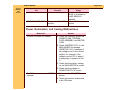
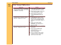
Power, Illumination, and Cooling Malfunctions
Malfunction
The MOTOR does not operate.
Solution
1. Check the continuity across the
POWER FUSE, THERMAL
FUSE ASSEMBLY, and MOTOR
FUSE.
2. Check VARISTOR V101 on the
MAIN BOARD for damage.
VARISTOR V101 is damaged if
the voltage is not in the correct
position, for example, if the
voltage is set at 130 V when it
is necessary to operate at 240
V.
3. Check that the primary voltage
on the MAIN MOTOR is correct.
The FAN does not operate, MOTOR
operates.
4. Check that the voltage on
POWER SWITCH is correct.
1. Check that the FAN BELT is not
broken.
2. Check and remove obstructions
in the FAN area.
SERVICE MANUAL
23JUL01
SM5766-1
Page
81 of 96
Diagnostics
Malfunction
There is excessive noise in the
FAN.
Solution
1. Check and remove obstructions
in the FAN area.
2. Check that the tension is correct
on the FAN BELT.
3. Check that the FAN BELT is
clean.
4. Check the condition of the
BEARING in the FAN
ASSEMBLY.
SERVICE MANUAL
23JUL01
SM5766-1
Page
82 of 96
Diagnostics
Malfunction
The LAMP ASSEMBLY does not
operate.
Solution
1. Check the LAMP ASSEMBLY for
damage.
2. Check the LAMP RECEPTACLE
ASSEMBLY for damage.
3. Manually actuate the
INTERLOCK SWITCH, then
check that the voltage is correct
across the LAMP RECEPTACLE
ASSEMBLY. If you do not
manually actuate the
INTERLOCK SWITCH, there will
be no voltage across the LAMP
RECEPTACLE ASSEMBLY.
4. Check that the voltage is correct
across the TRIAC on the MAIN
BOARD.
5. Check the LAMP TERMINAL
ASSEMBLY in the LAMP
MODULE ASSEMBLY for
damage.
6. Check the “EXT/INT” SWITCH;
it should be in the “INT”
position.
• For 2000 PROJECTORS
Only: All THERMAL FUSES
and the LAMP MODULE
operate correctly.
SERVICE MANUAL
23JUL01
SM5766-1
Page
83 of 96
Diagnostics
Malfunction
The LO LAMP does not operate.
Solution
1. Check that the W of the
DROPPING RESISTOR is 3 W.
2. Check that the wire connections
on the POWER SWITCH are
correct.
There is an obstruction in the light
path.
3. Check the POWER SWITCH for
correct operation.
1. Check the DARK SHUTTER for
correct operation. See the
adjustment for the DARK
SHUTTER.
2. Check the LIGHT BAFFLE in
the MECHANISM for damage; it
should not cause a jam in the
SHUTTER.
SERVICE MANUAL
23JUL01
SM5766-1
Page
84 of 96
Diagnostics
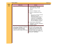
Slide Transport Malfunctions
Malfunction
Forward and reverse do not operate
using the FRONT PANEL BUTTONS
or REMOTE CONTROL.
Forward does not operate, reverse
operates, voltages are correct.
Reverse does not operate, forward
operates, voltages are correct.
Solution
1. Check that the secondary voltage
on the MAIN MOTOR is correct.
2. Check that the voltage across the
CYCLE SOLENOID is correct.
3. Check that the W across the
CYCLE SOLENOID COIL are
correct.
1. Check that the CYCLE LEVER
and RATCHET PLATE are clean.
Clean and lubricate the parts as
necessary. Use SUPER LUBE TL4276.
2. Install a new CAM STACK
ASSEMBLY; the malfunction is
within the CAM.
1. Do the adjustment for the CYCLE
SOLENOID.
2. Check that the DIRECTION
LEVER SPRING is on the
DIRECTION LEVER.
3. Check the DIRECTION LEVER
for binds. Excessive lubrication
and dirt can cause binds.
SERVICE MANUAL
23JUL01
SM5766-1
Page
85 of 96
Diagnostics
Malfunction
Projector does not complete a cycle;
FAN operates.
Solution
1. Check for a broken MECHANISM
DRIVE BELT.
2. Check the CYCLE LEVER and
RATCHET LEVER on the CAM
SHAFT ASSEMBLY for the
following:
• correct alignment of the
CYCLE LEVER
• damage to parts
• lubrication of the CYCLE
LEVER (use SUPER LUBE
TL-4276)
3. Check the CYCLE SOLENOID for
correct operation. See the Voltage
chart.
SERVICE MANUAL
23JUL01
SM5766-1
Page
86 of 96
Diagnostics
Malfunction
Projector has continual cycle.
Solution
1. Check the CYCLE LEVER for
correct alignment. See the
adjustment for the CYCLE
LEVER.
2. Check for damage to parts.
3. Check for a short•circuit in the
wires:
• Use a tool to hold the CYCLE
LEVER down on the
RATCHET LEVER. If there is
a short•circuit causing the
malfunction, the SOLENOID
will be energized. If there is a
bind, the CAM will not rotate.
4. Check that the CAM SHAFT
ASSEMBLY RATCHET SPRING is
installed correctly.
The projector does not change cycles The CYCLE LEVER and the
when using a DISSOLVE CONTROL; RATCHET PLATE are dirty. Clean
the REMOTE CONTROL and
and apply lubricant SUPER LUBE
CONTROL PANEL BUTTONS
TL-4276 to the CYCLE LEVER and
operate correctly. (Model 2000 Only) RATCHET PLATE. If this does not
correct the malfunction, install a new
CAM SHAFT ASSEMBLY.
SERVICE MANUAL
23JUL01
SM5766-1
Page
87 of 96
Diagnostics
Malfunction
SLIDE TRAY does not advance
smoothly.
Solution
1. Check the SLIDE TRAY LATCH
for correct alignment.
2. Operate the projector in the
forward direction.
• Check that the INDEXER
LEVER ASSEMBLY is in the
correct alignment with the
holes at positions A and B.
• Do the adjustment for the
INDEXER LEVER ASSEMBLY.
• Check the condition of the
LOCATOR LEVER, it should
not be bent.
SLIDE TRAY advances when
“REVERSE” is pressed.
• Check the height of the SLIDE
LIFT LEVER; the lower corner
of the LIFT LEVER LAMP is
parallel with the TOP
HOUSING. If the height is not
correct, do the adjustment for
the MANUAL and POWER
SLIDE LIFT LEVER
ECCENTRICS.
1. Do the adjustment for the CYCLE
SOLENOID.
2. Check for a bind in the
DIRECTION LEVER ASSEMBLY.
3. Check that the DIRECTION
LEVER LINK is in the correct
position.
SERVICE MANUAL
23JUL01
SM5766-1
Page
88 of 96
Diagnostics
Malfunction
SLIDE TRAY does not rotate freely
when the SELECT BUTTON is
pressed down. The projector has
power.
Solution
1. Press and release the SELECT
BUTTON.
• Check that the LOCATOR
LEVER moves correctly and is
not bent.
2. Press and hold the SELECT
BUTTON down.
• Check the SLIDE LIFT LEVER
RAMP for damage.
TIMER (Models 1500 and 2000 Only)
does not operate
3. Check the height of the SLIDE
LIFT LEVER; the lower corner of
the LIFT LEVER LAMP is parallel
with the TOP HOUSING. If the
height is not correct, do the
adjustment for the MANUAL and
POWER SLIDE LIFT LEVER
ECCENTRICS.
1. Check the VARIABLE RESISTOR
for correct operation and install a
new part if necessary.
2. Move the TIMER BUTTON
forward and backward; use a
DVM to check for changes in W.
3. Energize the projector and move
the TIMER to “S”.
• Check the voltages on CR3,
Q3, and Q4, see the voltage
table.
SERVICE MANUAL
23JUL01
SM5766-1
Page
89 of 96
Diagnostics
Malfunction
DARK SHUTTER SWITCH (Model
2000 Only) does not operate
Solution
1. Energize the projector and
release the DARK SHUTTER to
allow projection.
2. Check for continuity between
PINS A6 and B1 on the 12-PIN
DISSOLVE PLUG.
3. Press the “FORWARD” or
“REVERSE” BUTTONS to close
the DARK SHUTTER.
4. In the closed position, the DVM
should measure 0 W.
5. If this procedure does not correct
the malfunction, install a new
DARK SHUTTER SWITCH.
SERVICE MANUAL
23JUL01
SM5766-1
Page
90 of 96
Diagnostics
Malfunction
ZERO POSITION SWITCH (Model
2000 only) does not operate
Solution
1. De-energize the projector.
2. Check for continuity between PIN
B5 and B6 on the 12-PIN
DISSOLVE PLUG.
3. Install a SLIDE TRAY.
4. Rotate the SLIDE TRAY to
engage the ZERO POSITION
SWITCH, the DVM should
measure 0 W.
5. If the W measurement is not
correct, see the adjustment for the
ZERO POSITION SWITCH. Install
a new ZERO POSITION SWITCH
if necessary.
After the FOCUS MOTOR energizes
and moves, the FOCUS MOTOR
oscillates.
1. Remove R3 and install a new 68K
W 1/4 W RESISTOR (part
220040).
2. If there is still a malfunction,
install a new PHOTOCELL.
SERVICE MANUAL
23JUL01
SM5766-1
Page
91 of 96
Diagnostics
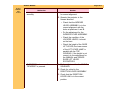
Focus Malfunctions
Malfunction
No manual focus
Solution
1. Check the FOCUS SHAFT
SPRING for the correct tension.
2. Check the LENS SUPPORT
SPRING for correct tension.
No remote focus (Models 500 and
1000)
3. Check the LENS DRIVE GEAR on
the FOCUS SHAFT ASSEMBLY
for damage and install a new part
if necessary.
1. Check the REMOTE CORD for
damage; use a REMOTE CORD
that has no damage.
2. Actuate and hold the REMOTE
CONTROL.
3. Check that the voltage across the
FOCUS MOTOR is correct.
4. Check that the secondary voltage
on the MAIN MOTOR is correct.
FOCUS MOTOR is energized and
This condition will occur only when
operating for a short time when the
the MAIN MOTOR is operating at the
REMOTE CONTROL CORD is
same time you connect the REMOTE
connected when the MAIN MOTOR is CONTROL. It will not occur if the
on (Models 500 and 1000 Only)
MAIN MOTOR is not operating. This
is a normal condition; there is no
procedure to correct this condition.
SERVICE MANUAL
23JUL01
SM5766-1
Page
92 of 96
Diagnostics
Malfunction
No remote focus (Modes 1500 and
2000, RACK SOLENOID ASSEMBLY
operates)
Solution
1. Check that the REMOTE CORD
operates correctly; use a
REMOTE CORD you know is
good.
2. Actuate and hold the REMOTE
CONTROL.
3. Check that the voltage across the
FOCUS MOTOR is correct.
4. Check the AUTO FOCUS
SWITCH ASSEMBLY for correct
operation.
5. Check the secondary voltages on
the MAIN MOTOR.
SERVICE MANUAL
23JUL01
SM5766-1
Page
93 of 96
Diagnostics
Malfunction
No auto-focus (Models 1500 and
2000 Only)
Solution
1. Check that the AUTO-FOCUS
DEFEAT SWITCH is in the “ON”
position.
2. Check that the MAIN
PROJECTION LAMP operates
correctly.
3. Insert the TARGET SLIDE TL3002 in the GATE MECHANISM.
• Check that the TARGET is
correctly aligned. If not, see
the Adjustment section.
4. Check that the voltages across the
PHOTOCELL are correct. The
voltage from 1 to 2 is 14.5 V ac.
The voltage from 2 to 3 is 14.5 V
ac. The voltage from 1 to 3 is 29
V ac.
5. Make a short• between 1 and 2;
the FOCUS MOTOR should rotate.
6. Make a short•circuit between 2
and 3; the FOCUS MOTOR
should rotate in the reverse
direction.
7. If the FOCUS MOTOR operates
correctly, install a new
PHOTOCELL. If the FOCUS
MOTOR does not operate
correctly, measure the voltages on
the BOARD.
SERVICE MANUAL
23JUL01
SM5766-1
Page
94 of 96
Diagnostics
Malfunction
Slow auto-focus movement (Models
1500 and 2000 only)
Solution
1. Check that the alignment of the
FOCUS LIGHT PATH and NULL is
correct.
2. Check the resolution of the
FOCUS LIGHT PATH. Clean the
AUTO FOCUS MIRROR and
BRACKET ASSEMBLY.
3. Install a new PROJECTION LAMP
if necessary.
4. Install a new PHOTOCELL.
5. Check the components on the
BOARD for damage.
SERVICE MANUAL
23JUL01
SM5766-1
Page
95 of 96
Diagnostics
Malfunction
AUTO FOCUS MOTOR operates
continually (Models 1500 and 2000
Only)
Solution
1. Install the TARGET SLIDE TL3002 in the GATE MECHANISM.
2. Check that the alignment of the
TARGET and NULL is correct. If
not, see the Adjustments section.
3. Check for a light leak:
• Install a different LAMP
MODULE ASSEMBLY. If the
FOCUS MOTOR stops
operating continually, install a
new LAMP MODULE
ASSEMBLY.
4. Check that the voltages across the
PHOTOCELL are correct. The
voltage from 1 to 2 is 14.5 V ac.
The voltage from 2 to 3 is 14.5 V
ac. The voltage from 1 to 3 is 29
V ac.
5. Check that the PHOTOCELL
HOUSING has 2 FILTERS.
6. Install a new PHOTOCELL.
7. Check the components on the
BOARD for damage.
AUTO FOCUS MOTOR operates
Check that the wires of the AUTO
continually in forward only or reverse FOCUS MOTOR are in the correct
only and does not operate (stops) in
position; the blue wire goes to the
the null position.
mark on the AUTO FOCUS MOTOR.
AUTO FOCUS adjusts after REMOTE Do the adjustment for the CLAMP
use
LEVER ASSEMBLY.
SERVICE MANUAL
Diagnostics
23JUL01
SM5766-1
Page
96 of 96
Kodak and Ektalite are trademarks.
Printed in U.S.A. • sm5766_1.fm
EASTMAN KODAK COMPANY
Rochester, NY 14650