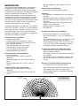
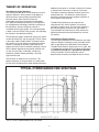
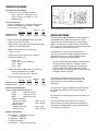
1
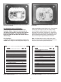
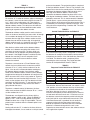
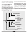
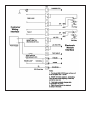
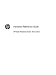
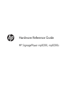
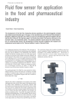
OMNIGUARD®
660 and 860 SERIES OPTICAL
FLAME DETECTORS
INSTALLATION AND OPERATING
SERVICE MANUAL
ISO 9000
CERTIFIED
OMNIGUARD Sensors Division
Meggitt Avionics Inc
10 Ammon Drive
Manchester, NH 03103-7406
Publication No. 1031229 Rev. C
TABLE OF CONTENTS
Description . . . . . . . . . . . . . . . . . . . . . . . . . . . . . . . . . . . . . . . . . . . . . . . . . . 1
Theory of Operation . . . . . . . . . . . . . . . . . . . . . . . . . . . . . . . . . . . . . . . . . . . 2
Specifications . . . . . . . . . . . . . . . . . . . . . . . . . . . . . . . . . . . . . . . . . . . . . . . . 3
Applications . . . . . . . . . . . . . . . . . . . . . . . . . . . . . . . . . . . . . . . . . . . . . . . . . 3
Installation . . . . . . . . . . . . . . . . . . . . . . . . . . . . . . . . . . . . . . . . . . . . . . . . . . . 4
Electronics . . . . . . . . . . . . . . . . . . . . . . . . . . . . . . . . . . . . . . . . 4, 5, 6, 7, 8, 9,
Maintenance and Troubleshooting . . . . . . . . . . . . . . . . . . . . . . . . . 9, 10, 11
Service and Repair . . . . . . . . . . . . . . . . . . . . . . . . . . . . . . . . . . . . . . . . . . . 11
Warranty . . . . . . . . . . . . . . . . . . . . . . . . . . . . . . . . . . . . . . . . . . . . . . . . . . . 12
Part Number Key . . . . . . . . . . . . . . . . . . . . . . . . . . . . . . . . . . . . . . . . . . . . 12
CAUTION!!
Electrostatic Discharge:
A discharge of static electricity from an ungrounded source including the
human body, may damage the electronic circuitry of the Omniguard®
Series 660 and 860 Flame Detectors. Use one or more of the following
methods when handling or installing electrostatic sensitive parts:
• A wrist strap connected by a ground cord to an earth ground source
• Heelstraps, toestraps, or bootstraps at standing workstations
• Conductive field service tools
• A portable field service kit with a static-dissipating work mat.
DESCRIPTION
• Storage Temperature: -85°F to 302°F (-65°C to
150°C).
Optional Features (All Models)
• Stainless Steel Housing (explosion-proof).
The Omniguard 660 and 860 Series Flame Detectors
are optically based, self-contained, microprocessor
controlled, ultraviolet/infrared (UV/IR) and high-speed
ultraviolet (UV) flame detectors. The 860 Flame Detector
utilizes the patented Fire Event Analysis (FEA)™
discrimination technology. These Flame Detectors are
compatible with most alarm panels without the need for
a controller. All electronics are housed within a copperfree aluminum, high temperature, TGIC-Polyester coated
enclosure with a 3/4-14NPT or M20-1.5 conduit entry.
A stainless steel enclosure is also available.
®
Approvals:
• The detectors are approved by most major approval
agencies.
• Certified to MIL-STD-461C, EMI/RFI susceptibility,
IEC 801-2 ESD and surge susceptibility test, and
IEC 801-5.
• Passes requirements of MIL-STD 810E for shock
vibration, rain and humidity.
• European Rating - EExd IIB + H2 T5.
• CE approved
The 660 and 860 Series Flame Detectors are suitable for
use in Class I, Division 1, Groups B, C and D (explosionproof) areas and Class II, Division 1, Groups E, F, and G
(dust-ignition-proof) areas. The housings are NEMA 4,
dust-tight and watertight. The detectors are approved for
both indoor and outdoor installations.
Fire Detection Performance (All Models)
• 50 millisecond response to a saturating signal.
• One second typical to a 1 ft. by 1 ft. gasoline fire at
50 feet.
• Two seconds or less to a 2 ft. x 2 ft. fire of JP-4, JP-8,
Jet A, Jet B, AVTUR and AVGAS at 100 feet.
• Three seconds or less to a 10 ft. x 10 ft. fire of JP-4,
JP-8, Jet A, Jet B, AVTUR and AVGAS at 250 feet.
• 120 degree horizontal field-of-view (Figure 1).
Standard Features (All Models)
• Microprocessor Based.
• 0 to 60 seconds user adjustable time delays.
• User adjustable latching or non-latching fire relays.
• User adjustable sensitivity.
• User adjustable NO or NC relay outputs.
• LED indication: fire (red), fault (amber).
• Transient voltage (surge) protection.
• RS485 addressable user interface.
Fire Detection Performance (Model 860-1XXXX)
• 340 milliseconds or less to a silane flame from a
0.010 inch orifice at 30 feet.
• 2.9 seconds or less to an 8 inch diameter hydrazine
fire at 60 feet.
• 3.0 seconds or less to a hydrogen flame from a 0.75
inch diameter orifice with a flow rate 1.5 SCFM at
35 feet.
Standard Features (Industrial Models)
• 0 to 20 mA output.
• Relay contacts rated at 2 Amps @ 30 VDC
(Resistive).
• Operating Temperature: -40°F to 185°F (-40°C to
85°C).
• Storage Temperature: -85°F to 212°F (-65°C to
100°C).
Response Time (Model 660 High Speed Setting)
• 15 milliseconds to a saturating UV source.
Standard Features (High Temp. Model)
• Relay contacts rated at 4 Amps @ 30 VDC
(Resistive).
• Operating Temperature: -40°F to 257°F (-40°C to
125°C).
4.5 SEC. RESPONSE
TIME TYPICAL
Note: Detector response times and distances can be
influenced by wind, smoke and viewing angle.
Consult Meggitt Avionics Inc. Application Engineers
for specific details.
0
0
-15
0
00
-5
1 SECOND RESPONSE
TIME TYPICAL
0
+5
+15 0
-25
+2
5
(ACTUAL DETECTION DISTANCE WILL BE GREATER)
+3
0
-35
DETECTION PERFORMANCE ENVELOPE
TO A 1'X1' PAN FIRE SOURCE
0
5
0
50
+4
0
+5
-5
50
-4
5
0
+75
-75 0
0
5
+6
-65 0
0
5
0
-85 0
+85
5'
15'
(FIG 1) MODEL 660/860 FLAME DETECTOR HORIZONTAL FIELD OF VIEW
-1-
25'
35'
45'
55'
THEORY OF OPERATION
Additionally the option is available in which the IR sensor
is responsive to 2.9 microns as well as 4.4 microns.
This option enables the detector to sense certain nonhydrocarbon fires. The detector’s autonull feature
eliminates interference due to background radiation in
these regions of the spectrum.
The 860 Series Flame Detectors
The Omniguard® 860 Series Flame Detectors are multispectrum detectors, which provide a high degree of
discrimination by sensing widely separated flame
emission spectra, both of which are found in
hydrocarbon and certain specified non-hydrocarbon
fires. Sophisticated signal processing is accomplished
by microprocessor technology. Automatic self-testing of
the electronics, sensors and optical surfaces is
accomplished using light guides. This self-interrogation
is done a minimum of four times per hour, thus providing
the ultimate in fire detection reliability.
The 860 Flame Detector not only requires the
coexistence of UV and IR radiation, but also their
presence in specific ratios. The ratio must conform to
the radiation pattern of specific fires (see Figure 2).
This patented Fire Event Analysis (FEA) ensures the
highest possible discrimination between fire and nonfire sources.
The two spectral regions selected for sensing fire signals
are the Ultraviolet (UV) and Infrared (IR). The UV sensor
is the stable, highly reliable Edison® UV photon sensor
tube which has a peak response centered around 0.22
microns. The design of the tube is optimized for the
highest sensitivity to the UV radiation emitted by a flame
with the lowest response to background radiation such
as near UV, black light, visible light, sunlight and
blackbody radiation, thereby providing a very high
signal-to-noise ratio.
The 660 Series Flame Detectors
The Omniguard® 660 Series Flame Detectors are single
spectrum detectors utilizing the same ultraviolet sensor
tube as described for the 860 Series Flame Detector.
The 660 Flame Detector requires only that a signal, with
in the detection envelope of the UV sensor, be present in
a pre-defined strength for a specified time duration.
These parameters are user adjustable and will
determine the sensitivity and response time to all fires.
The IR sensor is responsive to 4.4 microns. This
Spectral frequency is always present in a hydrocarbon
fire due to the excitation of hot carbon dioxide molecules.
(FIG 2) TYPICAL HYDROCARBON FIRE SPECTRUM
-2-
SPECIFICATIONS
4.50
(114.3)
OPTIONAL
SWIVEL MOUNT
PART NUMBER
4651027
The Omniguard® 660 and 860 Series Flame Detectors
are designed for fire detection applications where
sudden fires from hydrocarbon fuels or when proper
options are selected, from specified non-hydrocarbon
fuels, may occur. These detectors are not recommended
for smoldering, or electrical fire hazards.
The following is a partial list of fuels, which emit
ultraviolet and infrared radiation. Response time and
detection distances vary. Consult Meggitt Avionics
applications engineers for specific details:
• Current Loop Output (0 to 20 mA) - Industrial
Temperature Models Only
Fire
UV or IR only (860 only)
Normal
Fault
Hydraulic fluid, Methyl-Ethyl-Ketone, wood products,
jet fuels, Methane, Kerosene, Propane, plastics,
gasoline, Propylene, Acetone, fuel oil, Acetylene,
Methyl alcohol, Ethyl alcohol, Isopropyl alcohol,
Heptane, Toluene, Epoxy powders, crude oil, Butane,
Hydrogen, Hydrazine, Silane.
• RS485 Half-duplex, Addressable, User Interface
Baud Rate 9600 bits per second
1 start bit, 8 data bits and 1 stop bit
• Power consumption (@ 24 VDC)
Standby
2.16 W
2.16 W
Alarm
2.64 W
2.64 W
Weight: Aluminum housing – 5 lbs. (2.3 kg.).
Stainless Steel housing – 3 lbs. (5.8 kg.).
APPLICATIONS
Note: Each detector contains two relays:
(1) Fire, (1) Fault.
860/660-XX0XX
860/660-XX1XX
CONDUIT ENTRY
(FIG 3) 660/860 MECHANICAL SPECIFICATIONS
• Relay Contact rating (860/660 Industrial Models)
2 Amps @ 30 VDC (Resistive)
Relay Contact rating (660 High Temperature Model)
4 Amps @ 30 VDC (Resistive)
Manual
Test
N/A
6W
5.50
(139.7)
5.50
(139.7)
Electrical Interface
• Nominal voltage input —24VDC(20 Min/32 Max).
• Maximum allowable ripple voltage — 240mV
• Current Draw (@ 24 VDC):
Manual
Auto
Standby
Alarm
Test
Test
860/660-XX0XX 90mA
110mA
N/A
N/A
860/660-XX1XX 90mA
110mA 250mA 250mA
20 mA
16 mA
4 mA
0 mA
5.86
(148.8)
3.10
(78.7)
Environmental (All Models)
• Suitable for use in hazardous locations:
Class I, Division 1, Groups B, C & D
Class II, Division 1, Groups E, F & G
NEMA 4 rated.
The rugged, weatherproof construction and the
operating temperature range of the detectors will
accommodate a variety of indoor and outdoor
applications.
Auto
Test
N/A
6W
The Omniguard® 660 and 860 Series Flame Detectors
have been approved by major third party approval
agencies.
Mechanical Specifications
(Figure 3 Shows Nominal Dimensions)
Length:
5.98 inches (max).
Height:
4.90 inches (max).
Width:
5.50 inches (max).
Weights: (installed)
Aluminum Housing
5.0 lbs (2.4 kg).
Stainless Steel
13 lbs (6.3 kg)
Shipping weight:
Aluminum Housing
6 lbs (2.8 kg).
Stainless Steel
14 lbs (6.7 kg)
All installations should comply with local fire codes and
regulations
Do not proceed with the installation if you do not
understand the installation procedure or operation of
the detectors. Meggitt Avionics applications engineers
are available to assist you.
Optional accessories
Swivel Mount — 4651027 (aluminum)
(Shown in Figure 3)
Air Shield Kit — 8001023
Portable Test Source
Swivel Mount — 70991 (stainless steel)
-3-
FPO
INSTALLATION
6. Use a 20 to 32 Vdc regulated and filtered power supply,
with a ripple not exceeding 1 percent. The detectors
should be protected from induced and transients voltages
as well as radio frequency interference (RFI). To ensure
compliance to CE requirements, a dedicated conduit is
highly recommended for the detector wiring. Connect
every detector housing to earth ground via an
independent wire.
To ensure trouble-free operation and reliable fire
protection, follow these installation guidelines:
1. Locate the Detector(s) in an area where they will
have an unobstructed view of the area to be protected
and where extraneous sources of ultraviolet radiation will
not affect the performance of the fire detectors. These
sources include but are not limited to, nuclear radiation,
x-rays, electrical corona, and unshielded quartz halogen
lamps. Prolonged exposure to a continuous source of
UV radiation will diminish false alarm discrimination.
The detectors must be accessible for cleaning. Failure
to maintain clean sensor windows, and self-test optics,
when so equipped, will impair the performance of the
detector.
2. Separate the base from the housing by removing the
four M8 x 1.25 cap screws. This will require a 6mm hex
key. Store the housing assembly, containing the
electronics, in a clean and dry environment, while
installing the base.
3. Mount the detector base to a previously installed
swivel mount or other appropriate support structure so
that the detector has an unobstructed view of the area
to be protected. Position the base such that the conduit
opening faces down. It will be necessary to seal the
conduit within 18 inches of the fire detector enclosure.
This will insure that water and airborne moisture do not
enter the detector housing through the conduit. Provide
conduit drains as necessary to prevent moisture from
collecting inside the conduit.
4. Determine the critical areas where fires are most likely
to occur. Use these areas as focal points for aiming the
detectors. The detectors have a conical field-of-vision as
shown earlier in Figure 1. The type of fuel and the size
of the fire will determine the range of detection. Aim the
detector at a point equal to, or below horizontal, so that
water, dust and dirt will not accumulate on the optical
surfaces of the detector. As a general rule, mount the
detector so that it will view the base of the area to be
protected.
(FIG 4) WIRING DIAGRAM
ELECTRONICS
User Selectable Factory Settings
The electronic module has been factory configured to
provide the user with the following:
Time Delay:
Sensitivity:
5. Complete the installation by wiring the detector
according to wiring diagram (Figure 4). Before assembling
the detector housing to the base, verify that the terminal
block assembly is plugged in all the way and is located at
the top. Insure that the wires are arranged so as not to
interfere with the main electronics module. If a Torque
wrench is available, it is recommended that the four
cap screws be tightened to a value of 35 to 40 in-lbs.
(3.95 to 4.52 NM).
(660/860) 3 Seconds (fire),
(860) 35 Seconds (UV or IR warning)
(860) Fire Event Analysis Level I,
Industrial.
(660) Level 2, Normal
Relays:
Fire
Fault
Normally Open, Latching.
Normally Open, (Relay is failsafe, it
closes upon application of power to
detector), non-latching (cleared after
successful test).
Optical Self-Test:
Automatic (Only Self-Test
Models)
0 to 20 mA
(660-0XXXX/860-XXXXX) “OFF”
Note: The electronics module contains no re-useable
parts. It should never be removed from the housing
assembly. This will result in the voiding of the warranty.
RS485 (660/860) “OFF” — HI-Z mode
-4-
Jumpers
Fuse
Jumpers
Fuse
Fire Time
Delay
UV or IR Time Delay
Configuration
Switches
Fire Time Delay
Configuration
Switches
(FIG 5) 660-0XXXX AND 860-XXXXX USER SELECTABLE
OPTIONS LOCATIONS
(FIG 6) 660-1XXXX USER SELECTABLE OPTIONS
LOCATIONS
User Selectable Interface (USI) Options
(Refer to Figures 5 and 6 for Locations of User
selectable Options. Figures 7,8 and 9 provide the
user with a quick reference of switch setting options
for the various models. The text following these
figures describes in more detail the function of each
switch setting.
to 63 seconds before annunciation of a fire. If the fire were
to extinguish anytime prior to the end of the set delay
time, the detector would not declare a fire. The factory
setting for this delay time is 3 seconds. To adjust the fire
outputs delay time, use Potentiometer (Pot) R49. Turning
the Pot counterclockwise (CCW) will decrease the time
delay. One turn equals approximately five seconds.
Fire Time Delay
— Models 660-0XXXX and 860-XXXXX and Model 6601XXXX The fire outputs can be configured to delay for up
Note: If the Model 660 is using the high speed option,
then the maximum delay time setting will be one second.
Each turn of the Pot will equal 50 milliseconds.
SPST DIP SWITCH (S1) LOCATED ON BOARD P/N 71043
SPST DIP SWITCH (S1) LOCATED ON BOARD P/N 71043
OPTION
OFF
ON
Automatic & Manual Test Activated
1, 2
No Test Feature
1, 2
Manual Test Only
2
1
* Automatic Test Only
1
2
* Industrial Applications
3
Aircraft Hangar Applications
3
* Fire Event Analysis Level I
4
Fire Event Analysis Level II
4
IR/UV Alarm
5
* No IR/UV Alarm
5
* Fire Output Latching
6
Fire Output Non-latching
6
0 to 20mA
7
* No 0 to 20 mA
7
RS485 UI
8
* No RS486 UI
8
Program
9
* No Program
9
* Denotes factory settings for auto test units only
OPTION
OFF
ON
Automatic & Manual Test Activated
1, 2
No Test Feature
1, 2
Manual Test Only
2
1
* Automatic Test Only
1
2
Sensitivity — Level 1
3,4
*
— Level 2
3
4
— Level 3
4
3
— Level 4
3,4
* Detection Speed — Normal Speed
5
— High Speed
5
* Fire Output Latching
6
Fire Output Non-latching
6
0 to 20mA
7
* No 0 to 20 mA
7
RS485 UI
8
* No RS486 UI
8
Program
9
* No Program
9
* Denotes factory settings for auto test units only
(FIG 8) SWITCH CONFIGURATIONS FOR THE 660-0XXXX
UV FLAME DETECTOR
(FIG 7) SWITCH CONFIGURATIONS FOR THE 860-XXXXX
UV/IR FLAME DETECTOR
-5-
Detection Speed
— Model 660: Switch position 5 is used to select two
detection speeds. The normal speed utilizes a slower
sampling rate and automatic self-test interval. The highspeed setting increases the data sampling rate and auto
self-test frequency. Toggling switch position 5 “ON”
activates the normal speed option. Toggling switch
position 5 “OFF” activates the high-speed option. The
normal speed option is the factory setting and
recommended for most applications.
SPST DIP SWITCH (S1) LOCATED ON BOARD P/N 71044
OPTION
OFF
ON
Automatic & Manual Test Activated
1, 2
No Test Feature
1, 2
Manual Test Only
2
1
* Automatic Test Only
1
2
Sensitivity — Level 1
3,4
*
— Level 2
3
4
— Level 3
4
3
— Level 4
3,4
* Detection Speed — Normal Speed
5
— High Speed
5
* Fire Output Latching
6
Fire Output Non-latching
6
RS485 UI
7
* No RS486 UI
7
Program
8
* No Program
8
* Denotes factory settings for auto test units only
Industrial or Aircraft Hangar Applications
— Model 860: Switch position 3 is used to select the
application setting. If the detector is to be installed in
an industrial environment (i.e., fuel loading rack,
compressor building, and tank farm), switch position 3
should be “ON”. If the application is for an aircraft
hangar, switch position 3 should be “OFF”. The false
alarm immunity will be slightly diminished from that of
the industrial setting.
(FIG 9) SWITCH CONFIGURATIONS FOR THE 660-1XXXX
UV FLAME DETECTOR
Fire Event Analysis Level I or II
— Model 860: Switch position 4 allows the detector to
run the Fire Event Analysis (FEA) program of your
choice. FEA Level I is for installations with normal UV
background levels (i.e., no welding). FEA Level II should
be used where detectors are required to detect flames
while welding or other UV generating sources are
present. Turning switch 4 “ON” selects FEA Level I.
Turning switch 4 “OFF” will provide FEA Level II.
Level II has slightly diminished false alarm immunity
as compared with Level I.
UV or IR Warning
— Model 860: Switch position 5 is used to enable the UV
or IR Warning Outputs. If switch position 5 is “ON”, this
option is activated. If switch position 5 is “OFF”, this
option is not activated. This option will alert the user, to
the presence of high levels of either UV or IR within the
field-of-view of the fire detector.
UV or IR Time Delay
— Models 860: The UV or IR outputs can be configured
to delay for up to 63 seconds before annunciation of one
of these emissions. If the UV or IR signal disappeared
prior to the end of the set time delay, then the detector
would not allow the outputs to toggle “ON”. The factory
setting is 35 seconds. To adjust the UV or IR outputs time
delay, use Pot R48. Turning the Pot CCW will decrease
the time delay. One turn equals approximately five seconds.
Relay Adjustments
— Models 660-0XXXX and 860-XXXXX and Model 6601XXXX There are two relays, and Configuration Option
Jumpers, JP1 and JP2, located on the exposed surface
of the printed circuit board (PCB) in the housing
assembly. Using these jumpers, the relays may be
configured as normally open or closed. The factory will
ship the detectors with the following settings.
1.) Fire relay (K2) — normally open:
-will close when there is a fire present beyond
the fire time delay setting.
-will close when manual test is activated beyond
the length of time for the fire delay time setting.
Note: Always reset power to the detector after adjusting
the pots. The detector will not recognize any new setting
unless it is reset.
Sensitivity Levels
— Model 660 (Table 1): Switch positions 3 and 4 adjust
the sensitivity to four different levels. Level 1 being the
most sensitive to UV radiation and the most susceptible
to false alarms. Level 2 is the factory setting and is
recommended for most applications. The following are
the logic levels for the two switch positions:
Note: The red, light emitting diode (LED), will be
illuminated when relay transfers.
2.) Fault relay (K1) - normally open:
- will close when power is applied (Model 860
after 2 seconds and Model 660 less then a
second).
- will open when power is lost (or fuse F1 on
process PCB is open).
- will open when detector fails automatic test.
- will open when detector fails manual test.
Table 1 - Model 660 Sensitivity Settings
Sensitivity Level
1 (Max.)
2
3
4 (Min.)
Position 3
OFF
OFF
ON
ON
Position 4
OFF
ON
OFF
ON
Note: The amber LED will be illuminated when relay
transfers, unless there is a loss of power.
-6-
Note: Any adjustments to the user options listed above
should be done with the power “OFF”. The detectors will
not recognize any changes until the microprocessor is
reset. Removing the power does this.
Caution: Upon applying power, insure that the detector
remains on for at least 5 seconds to allow for complete
initialization to take place.
Fire Outputs Latching or Non-Latching
— Models 860 and 660, switch position 6 selects the
latching or non-latching Fire Outputs option. To select
latching, the switch position 6 must be toggled “ON”.
The Fire Outputs signal will remain engaged as long as
power remains “ON” or until the detector is reset through
the RS485 User Interface (UI). If you select non-latching
by toggling switch position 6 to “OFF”, then the Fire
Outputs signal will disengage after a fire is extinguished.
Optical Self-Test
— Models 660-XX1XX and 860-XX1XX: These models
have a “through-the-lens” optical clarity-checking
feature. The factory setting is for automatic test only,
switch position 1 is “OFF”, and switch position 2 is “ON”.
(See Figure 5 and 6 for location of the switches and
Figures 7,8 and 9 that describe the switch settings for
the user selectable interface.) If the addition of the
manual test feature is desired, then toggle the switch
position 1 to “ON”. If only the manual test feature is
needed, then toggle the switch position 1 “ON” and
switch position 2 “OFF”. If no optical testing is preferred,
then ensure that both of these switches are “OFF”.
Models 660-XX0XX and 860-XX0XX do not have either
the manual or the automatic test feature and do not test
the lens for optical clarity. Switch positions 1 and 2 are
non-applicable (N/A) in these detectors.
0 to 20 mA Output
— Models 660-0XXXX and 860-XXXXX switch position
7 selects the 0 to 20 mA output option. If this output is
utilized, then switch position 7 must be “ON” to engage
the peripheral. Otherwise, if this output is not used,
switch position 7 must be kept “OFF” or it will cause the
Fault Outputs to turn “ON”. Table 2 illustrates the order
of priority. For the Model 660-0XXXX, priority 2 is N/A.
TABLE 2 - Milliamp Logic Chart
Priority
State
Load Current mA
1
FIRE
20
2
UV-IR
16
3
FAULT
0
4
NORMAL
4
RS485 User Interface (UI)
The Series 660 and 860 Flame Detectors are equipped
with a two wire, half-duplex, serial communication
interface, which is called the “User Interface” (UI). The
RS485 UI will allow up to 31 detectors to be networked
to a controller (i.e., customized fire panel or personal
computer). The controller will perform the buss arbiter
duties, because the network is in half-duplex mode. This
means that only one transmitter is allowed on the
network at one time.
Activating The RS485 Option
On models 660-0XXXX and 860-XXXXX, switch
position 8 enables this option when it is toggled to the
“ON” position. It becomes disabled in the “OFF” position.
For model 660-1XXXX, switch position 7 performs this
task. This option provides the user with a half-duplex
serial communication network interface for up to 31
detectors.
The RS485 UI has two methods for configuring the
network. For either method, the unit has to be
programmed to a detector number from 01 through 31.
The detector number will give the Flame Detector an
address on the network. For the first method, the RS485
UI option is “ON”. If any alarm state changes, the
detector will send out an “Enquiry Interrupt” (EI). The EI
is the ASCII character “ENQ”, which is equal to the
number 5. Once a fire detector starts to transmit the EI
on the network, it will lock out any other detector from
sending out the EI. The detector will continue to transmit
the EI every second until the buss arbiter has requested
a status from it. For the second method, when the
RS485 UI option is “OFF”, the detector will be inhibited
from sending the EI. The network is still active, but the
detectors will only transmit information or perform a
function when the buss arbiter interrogates them. For
both methods, the detector will wait for a minimum of 16
ms before it will send a response to the buss arbiter.
This delay time allows for the buss arbiter to release the
network from its transmit mode.
NOTE: To determine the proper configuration of the RS485
UI refer to the firmware revision block on the nameplate,
which is a stamped pad located to the right of the model
name. The pad will contain a letter character to indicate
the firmware revision level.
The detector provides the RS485 UI with a “Status
Message”. After a status request is made, the detector
will send out for revision “A” a one-byte word that
represents the Status Message and starting with revision
“B” a six-byte response packet which the fourth byte
contains the status message. As shown in Table 3, the
status message has seven alarm bits and one valid
transmission bit. When bits 0 through 6 are at logic zero,
the alarms are “OFF”. When bits 0 through 6 are at logic
one, the alarms are “ON”. Bit 7 is always “ON”. For
revision “A”, it allows for error checking during
transmission. If a transmission occurs and bit 7 is not set,
then the trans-mission is not valid. Starting with revision
“B”, if bits 4 through 7 are set to logic one then the relay
coil is open. If bit 3 through 7 are set to logic one then the
non-volatile memory has been corrupted.
-7-
TABLE 3
Status Message for RS485 U
Bit 7
Always
On
Bit 6
Manual
Test
Fault
Bit 5
Bit 4
Bit 3
Bit 2
Bit 1
Auto
Auto Milliamp Warning Warning
Test IR Test UV Fault
IR
UV
Fault
Fault
packet to the network. The packet formation is comprised
of the byte definition shown in Table 4. The first byte is the
protocol start value for the control packet. The second byte
represents the detector address high byte which is the
tens digit of the detector address. The third byte
represents the detector address low byte, which is the
ones digit of the detector address. The fourth byte is the
secondary command. This is used to control the detector.
The fifth byte is a spare and may be used in the future.
The last byte is the checksum of the control packet. This is
calculated by first summing the previous five bytes. Then
taking the total and performing a modulus 256. The result
is the checksum.
TABLE 4
Control Packet Definition for RS485 UI
Bit 0
Fire
For revision “A”, in order for the buss arbiter to interrogate
the network, it must first send out an ASCII character “S”
or “s”, which is the number 83 or 115. Then the buss
arbiter must wait for 5 milliseconds before sending out a
detector address number. This delay time will allow the
detectors to exit from the flame detection mode and be
preparing to respond to the address number.
The detector address number must be sent by the buss
arbiter in the form of two ASCII characters from “0” through
“9” or numbers 30 through 39. The first character must
represent the tens digit of the address number and the
second character will be the ones digit. All single digit
address numbers such as 1 through 9 must have an ASCII
character “0” or number 30 sent for the tens digit.
Packet
Position
Byte
Byte
Byte
Byte
Byte
Byte
Byte
Byte
After the buss arbiter sends out the detector address
number and a detector recognizes the number, it will
send back the status message. The buss arbiter can
then continue until all detectors are polled throughout
the network. If the RS485 UI option is enabled and the
detector that sent the EI out was not polled. It will
continue to send the EI out once the buss arbiter
releases the network.
1
2
3
4
4
4
5
6
ASCII Byte Value
Byte Definition
‘K’
75d
4Bh
Protocol Start
‘0’ to ‘3’
48d to 51d 30h to 33h
Det. Addr. Hi-Byte
‘0’ to ‘9’
48d to 57d 30h to 39h Det. Addr. Lo-Byte
30h
No Sec. Command
‘0’
48d
‘T’
84d
54h
Init. Manual Test
‘R’
82d
52h
Unit Reset
‘0’
48d
30h
Spare
checksum=(Sum bytes 1..5) mod 256
If the transmission byte packet is recognized as valid, then
the detector will recognize the secondary command byte
and perform the function. If the “No Secondary Command”
is enabled. The detector sends a response packet
containing the status message. The packet formation
consists of the byte definition shown in Table 5.
To perform a manual test on a Flame Detector in the
network, the buss arbiter must first send out an ASCII
character “C” or “c”, which are the numbers 67 or 99.
Again, it has to wait 5 milliseconds before sending out
the detector address number. Once the buss arbiter
sends out the detector address number and the detector
recognizes the command, the detector will send back the
ASCII character ‘ACK’, which is the number 6. Then the
buss arbiter must send out the ASCII character “T” or “t”,
which are the numbers 84 or 116. The detector will then
send back an ASCII character “T” and enter the manual
test mode. The detector will stop manual test when it
gets polled for the status.
TABLE 5
Response Packet Definition for RS485 UI
Packet
Position
Byte
Byte
Byte
Byte
Byte
Byte
1
2
3
4
5
6
ASCII Byte Value
Byte Definition
53h
Protocol Start
‘S’
83d
‘0’ to ‘3’
48d to 51d 30h to 33h
Det. Addr. Hi-Byte
‘0’ to ‘9’
48d to 57d 30h to 39h Det. Addr. Lo-Byte
‘NA’
128d to 255d 80h to FFh
Status Byte
‘0’
48d
30h
Spare
checksum=(Sum bytes 1..5) mod 256
To enable the “Manual Test Command” turn switch 1 to the
“ON” position. In turn the detector test lamp is illuminated
for a period of time based on the customer selected fire
time delay. After the fire alarm is activated, the unit
transmits the response packet indicating the fire alarm bit
set and terminates the manual test. If a fault occurs, then
the detector transmits the response packet indicating the
maual test fault bit set and terminates manual test. If the
“Unit Reset Command” is provided, the unit sends the
response packet indicating the present status of the
detector and performs a software reset. An initialization
period of 2.3 seconds during which the unit is nonresponsive to communication occurs after software rests or
initial application of power.
To perform a network reset of all detectors, the buss
arbiter must send out the ASCII character ‘R’ or ‘r’, which
are the numbers 82 or 114.
The detectors are shipped from the factory with the
detector address number of ‘00’. When the RS485 UI
option is “OFF”, it will cause the detector to place the
RS485 line driver into a “High Z Output Mode”. This will
protect it from transients when the network option is not
being used.
Starting with revision “B”, in order for the buss arbiter to
interrogate the network, it must send out a six-byte control
-8-
Note: All detectors in the network must be programmed
to a valid detector address number from 01 through 31. For
Revision “A”, during the time that detectors are being polled,
they will be removed from fire detection mode. Therefore,
this should be done only when necessary and as quickly
as possible.
Programming the Detector Address Number
On models 660-0XXXX and 860-XXXXX, this option is
activated when switch position 9 is toggled “ON”. The
option is deactivated when the switch is in the “OFF”
position. For model 660-1XXXX, switch position 8
performs this task. This option provides the user with a
method of programming the unit number into the nonvolatile memory of the microprocessor.
To program the detector address number, first remove
power from the detector. Then toggle the program option
“ON” and set the first five switches on the user selectable
interface (USI) to the detector address number.
In program mode, the USI becomes a binary
programmer as illustrated in Table 4. When a switch
is toggled “ON”, it will equal the binary weighted number.
These binary weighted numbers are added together
when a multiple number of switches are switched “ON”
(i.e., if SW2 and SW3 were closed, then the detector
number would equal a 6).
SW1
1
SW2
2
SW3
4
SW4
8
SW5
16
TABLE 6
Binary Weight for Switch States “ON”
When power is applied to the detector. The detector will
sense that it is in program mode and read the first five
switch positions. From the switch setting, it will
determine the detector number. Once the number has
been determined, the detector will enter it into the nonvolatile memory of the microprocessor. Next, the amber
LED will flash “ON” a certain number of times. The
number of flashes will be equal to the detector’s address
number. Then it will hold the fault relay and amber LED
“ON” constantly for about 10 seconds. Then the detector
will repeat flashing the detector address number and the
delay time. It will continue this mode for up to 5 minutes.
MAINTENANCE AND
TROUBLESHOOTING
Omniguard® 660 and 860 Series Flame Detectors are
designed for years of trouble-free operation with minimal
attention. Periodic cleaning of the optical surfaces is
essential, however, for maintaining reliable fire
protection. The frequency of required cleaning will be
determined by the environmental conditions in and
around the installation. The detectors should be regularly
inspected for a build-up of dust or other contaminants on
the optical surfaces.
The detection specifications presented in this manual
are predicated on performance with clean sensor windows.
Contaminants such as dust, oil and paint will reduce
sensitivity. Severe contamination on the light guides or
sensor windows will cause a failure of the
auto-test. A detector that fails auto-test due to dirty
optical surfaces may be capable of detecting fire, but
its effectiveness will be limited.
Cleaning Procedure:
Locate the following optical surfaces: (Figure 10)
Models 660-XX1XX
1. UV Sensor Window
2. UV Light Guide End
Model 860-XX1XX
1. UV Sensor Window
2. UV Light Guide End
3. IR Sensor Window
4. IR Light Guide End
Note: Models 660-XX0XX and 860-XX0XX are not
equipped with light guides. Clean the optical surfaces
with a cotton swab wetted with commercial liquid glass
cleaner, ammonia, methanol, or isopropyl alcohol. Rinse
with clean water and dry with lens quality cloth. Repeat
with methanol if needed to remove smudges.
Caution: Wiping with excessive force or
inappropriate materials may scratch the optical
surfaces and impair performance.
UV WINDOW
Once you are sure that the proper number is
programmed, then shut the power “OFF” and set the USI
options to suit your application. Reference the section on
the USI, if you are not sure which option is best for your
application or call a Meggitt Avionics application engineer.
Note: In the case that the program option switch is left
“ON” and the detector is installed on the network. The
detector will go through the same process as explained
previously, but after 5 minutes the detector will resume
the last USI setting that it had prior to going into the
program mode.
LIGHT GUIDES
(FIG 10) OPTICAL SURFACES
-9-
IR WINDOW
Troubleshooting:
*WARNING* Do not attempt to repair a detector. Study
these troubleshooting guidelines and review the
referenced sections of the manual prior to performing
maintenance on the fire detection system.
Confidence Condition:
Model 660 and 860 Flame Detectors are equipped with a
fault relay to annunciate a change in the operational
status of the detector. When power is applied to the
detector, the fault relay will energize within 2 seconds.
A loss of power will cause the relay to de-energize.
New Installations:
If any or all the detectors fail to operate, check the
system wiring and power supply. Tight, reliable wiring
connections are essential, as are low-resistance
connections from every detector housing to earth
ground. Measure the voltage between terminals 8 and 10
at the detector locations, to verify that the supply voltage
is within range.
If the fault relay output fails to change state within 2
seconds after power-up and the amber LED fails to
illuminate. Then, there may be no power reaching the
detector’s electronic module. Check the supply voltage,
the condition of the fuse located at F1 on the PCB and
the wiring to terminals 8 and 10. Also, inspect the wiring
to the fault relay terminals 6 and 7 and the jumper JP1
that sets the fault relay option.
Note: Voltage at detectors installed farthest from power
source will be lower than the no-load supply voltage, due
to line losses. Maximum load condition occurs during
manual test.
Note: Models 660-0XXXX and 860-XXXXX Flame
Detectors are equipped with a 0 to 20 mA option. A loss
of power will result in a constant 0 mA output.
If the fault relay output continues to be inoperative,
isolate the relay contacts by disconnecting the external
wiring to the fault relay terminals. Connect an Ohmmeter
across the fault relay terminals and monitor for an
actuation of the relay. Repair the external wiring, if
necessary.
The Omniguard 660 and 860 ® Series Flame Detectors
employ sensitive and sophisticated electronic circuitry in
the fire detection process. Power line transients or
excessive power supply ripple may therefore cause
erratic or intermittent operation. DC-powered detectors
function best with ripple-free (less than 1 percent) supply
voltage; power supply filtering may be necessary to
improve performance.
Fault Condition:
Models 660-0XXXX and 860-XXXXX Flame Detectors
are equipped with a 0 to 20 mA output. When the 0 to 20
mA option is not used in your application, make sure that
the 0 to 20 mA option is “OFF” on the USI. If the 0 to 20
mA option is “ON” and at any time the drive line opens or
the current sense does not equate to what is suppose to
be there, it will cause the activation of the fault outputs.
Check the wire terminal 15 and insure that a good signal
ground is present at terminals 10 or 11. To insure that the
0 to 20 mA option causes the fault condition, toggle the
option on the USI “OFF” and reset the detector by
toggling the power off then on. If the fault condition
continues to be activated, then the problem is in a
different area.
Note: For reliable operation, the instantaneous supply
voltage at the input to any detector must not fall below 20
Vdc or exceed 32 Vdc.
Failure To Alarm:
Upon detection of fire, the fire outputs will activate and
the red LED, visible through the UV sensor window, will
turn “ON”.
If during testing, a detector fails to alarm, inspect the
sensor windows for cleanliness. Clean sensor windows
are essential for effective optical fire detection. Clean all
the optical surfaces per the cleaning procedures
previously described and retest the detector.
Models 660-XX1XX and 860-XX1XX Flame Detectors
are equipped with automatic self-test in addition to the
manual test. Approximately every 15 minutes, the
automatic self-test is actuated and for a brief time interval,
the optics and electronics are checked for functionality.
The exception to this is for the high-speed setting on 660
models. In this configuration (switch 5 “OFF”), self-test
is actuated approximately every 2 minutes. A failure of
the automatic self-test is annunciated by the activation
of the Fault Outputs. If a detector goes into a fault
condition, the optical surfaces should be checked for
cleanliness. Clean sensor windows and light guide ends
are necessary for the detector(s) to pass self-test.
Should the detector continue to be inoperative, check
the supply voltage and all associated wiring. Incorrect
power supply voltage or loose connections will cause
marginal or intermittent performance.
Alarm Condition - No Fire Present:
A detector in alarm condition when no fire is present may
be caused by an inadvertent actuation of the manual
test. Except for Models 660-XX0XX and 860-XX0XX, the
Series 660 and 860 Flame Detectors feature manually
initiated self-test of the optical and electronic systems.
Verify the light guides are illuminated. If they are, then
check the manual test wiring and the test switch for broken,
loose, or intermittent connections. Repair or tighten any
faulty connections. If the light guides are not illuminated,
then contact your Meggitt Avionics Representative.
After the optical surfaces have been inspected and
cleaned, reset the detector. If the detector is wired for
manual test, perform the manual test. The typical
response time should be from 0.6 seconds beyond the
actual fire output time delay.
-10-
*WARNING* During Manual Test, the fire output will be
actuated. Always disable extinguishing circuits before
testing.
If the detector continues to go into a fault condition
following a cleaning of the optical surfaces, check the
supply voltage and wiring terminals 8 or 9 and 10 or 11.
Look for loose or intermittent connections.
During normal operation, the fault outputs will change
state on power-up. The output will return to its original
state if power to the detector is removed. If the fault
output is intermittent or erratic, check the supply voltage
and wiring to terminals 8 or 9 and 10 or 11. Inspect the
fault relay wiring on the detectors. Repair or tighten any
loose connections.
For the Model 860, if the UV or IR option is “ON”, the
fault relay will be flashing at a 1 Hz rate whenever a fault
conditions exists.
Manual Test Failure:
*WARNING* This test will activate the fire outputs.
Always disable extinguishing circuits before testing.
A manual test is actuated by connecting the 660-XX1XX or
860-XX1XX test circuit terminal 12 to the plus terminal of
the detector’s input power supply (terminals 8 or 9). During
manual test, the optical and electronic systems of
a detector are checked. Upon successful completion of the
test, the fire outputs will be activated. Also, the red LED
inside the detector, visible through the UV window, will turn
“ON”. The typical response time is 0.6 seconds beyond
the actual fire output time delay. If the detector fails to
respond to a manual test, check to see if the USI manual
test option is “ON”. It will be switch 1.
If the detector fails manual test by activating the fault
outputs or the response time is longer than expected,
the optical surfaces of the detector may require cleaning.
Clean the sensor windows and light guide ends. After
cleaning, initiate the manual test.
If the detector again fails manual test, check the wiring
to the supply voltage terminals 8 or 9 and 10 or 11. The
detector may not be receiving enough power; the wiring
connections may be loose or intermittent. If the red LED
is illuminated and there is no fire output, then check all the
connections to the fire alarm panel or annunciating devices.
A defective test switch may prevent the test circuit from
initializing. Initiate the manual test by connecting a wire
from the test switch terminals to the positive terminal of
the input power supply. Replace the switch if the manual
test operates when the wire is connected.
UV or IR Warning:
In addition to detecting fire, the Omniguard® 860 Series
Flame Detectors will annunciate a warning of potentially
hazardous conditions that could cause a fire. For
example, welding, a process, which emits a far
greater proportion of UV radiation than IR, will cause
an
actuation of the UV or IR Outputs but not the Fire
Outputs. For this detector to actuate the Fire
Outputs,
it must sense the simultaneous presence of UV and
IR in a ratio characteristic of the fire type(s) to which
the detector is configured.
When the detector senses persistent source of intense
UV or IR radiation, such as welding, sparks, or radiant
heat, the UV or IR Outputs will change state. To
enable the UV or IR Outputs, the UV or IR option
(switch 5)
must be “ON”. When the UV or IR Outputs are
activated, it will cause the fault relay and the amber
LED to be“ON” constantly. If the 0 to 20 mA option is
“ON”, it will send the output to 16 ma. The UV or IR
warning are non-latching outputs and will change
states if the problem source is removed.
This alarm is used as a tool to help prevent unwanted
alarms. An UV or IR warning should always be investigated with caution. If possible, remove the source
of radiation, as a constant presence of UV may reduce
detector sensitivity and compromise its discrimination
ability. Inspect the protected area and beyond; UV
from source such as welding can be sensed at great
distances. If no radiation sources are apparent, cover
the detector with opaque material to test whether the
UV or IR warning disappears when the sensor
windows are blocked. Continue searching for the
source of UV or IR,if necessary. If the warning does
not disappear after blocking the windows, a sensor
may be faulty and in need of repair.
RS485 User Interface (UI)
If no communication has been established, check the
wiring to be sure that the polarity is not reversed on
the two wires. The network can be daisy chained, but
it does require two 120Ω terminating resistors in order
to minimize reflections. One resistor should be placed
at the controller or buss arbiter. The other resistor
should be placed at the farthest location from the
controller or buss arbiter. RS485 allows up to 4000
feet of 24 AGW twisted-pair wire driving into 120Ω
loads.
SERVICE AND REPAIR
Contact Meggitt Avionics or your Meggitt distributor for
service and repair information. Do not send material or
equipment to Meggitt without a return authorization.
When requesting a return authorization, state the
complete detector part number and serial number.
Omniguard® 660 and 860 Series Flame Detectors are
not field-serviceable. An unauthorized attempt to
repair or re-calibrate a detector will void the warranty.
Detectors should be carefully packed to avoid
damage from shock, moisture and dust. Use the
original shipping carton, if available. Wrap the
detector in plastic before packing. Provide ample
packing material to cushion the detector. For most
repairs, only the detector head will need to be
-11-
returned. After removing the head, cover the detector
base with plastic to protect the base from moisture
and dust, if a spare head is unavailable.
WARRANTY
The warranty period is thirty-six (36) months for the
Omniguard® 660 and 860 Series Flame Detectors and five
(5) years for both the UV and IR Sensors.
Meggitt Avionics Inc will, at its option, repair and return
without charge (freight prepaid) any Omniguard product,
used in accordance with Meggitt ratings and instructions
and confirmed by Meggitt to be defective in workmanship
or materials. This warranty shall be valid only if the product
is returned, within the applicable warranty period, to the
factory at Manchester, NH, USA properly packed and
with all transportation charges prepaid. All warranty
660-0
0
1
0
periods commence from the date the product is shipped
to the end user, provided that delivery is within six (6)
months of the date the product was originally shipped from
the factory. There are no warranties of merchantability,
fitness, or implied warranties of any kind, or representations
for any other Meggitt product, except the warranty
specified herein. In no event shall Meggitt be liable for any
consequential, special or other damages attributable to
our product. The buyer is solely responsible for the proper
installation, maintenance and use of the Omniguard®
Flame Detectors, and agrees Meggitt Avionics Inc is not in
any way liable for any special incidental or consequential
damages whatsoever.
0
AGENCY APPROVALS
FIRE RELAY CONFIGURATION
0 LATCHING
1 NON- LATCHING
TEST FEATURE
0 NO SELF-TEST
1 AUTO SELF-TEST
HOUSING MATERIAL/CONDUIT ENTRY
0 ALUMINUM 3/4-14 NPT (WHITE)
2 STAINLESS STEEL / 3/4-14 NPT
3 ALUMINUM / M20-1.5 (WHITE)
5 STAINLESS STEEL / M20-1.5
TEMPERATURE RATING
0 INDUSTRIAL TEMP.FIRE DETECTOR
1 HIGH TEMP.FIRE DETECTOR
Example: 660-00100
860-0
0
1
0
0
AGENCY APPROVALS
FIRE RELAY CONFIGURATION
0 LATCHING
1 NON- LATCHING
TEST FEATURE
0 NO SELF-TEST
1 AUTO SELF-TEST
HOUSING MATERIAL/CONDUIT ENTRY
0 ALUMINUM 3/4-14 NPT (WHITE)
2 STAINLESS STEEL / 3/4-14 NPT
3 ALUMINUM / M20-1.5 (WHITE)
5 STAINLESS STEEL / M20-1.5
FIRE TYPE
0 HYDROCARBON
1 HYDROCARBON / NON-HYDROCARBON
Example: 860-00100
-NOTES-
-12-
ISO 9000
CERTIFIED
OMNIGUARD Sensors Division
Meggitt Avionics Inc
10 Ammon Drive
Manchester, NH 03103-7406
Tel:603-669-0940
Fax: 603-669-0931
Email: [email protected]
http://meggittavi.com
AP 8/00