1
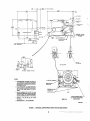
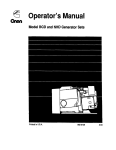
Installation
Manual
GenSets
u
0
LISTED
RV Electric Generating Set
This manual must be given to the customer,
along with the Operator’s Manual
965-0630
10-86
Printedin USA
Safety Precautions
This symbol warns of immediate
hazards which will result in severe
personal injury or death.
Follow all state and local electrical codes. Have all electrical
installations performed by a qualified licensed electrician.
Do Not Smoke While Servicing Batteries
6
This symbol refers to a hazard or
AW*R"'G
i unsafepractice which can result in
Severe personal injury or death.
Batteries emit a highly-explosive gas that can be ignited by
electrical arcing or by smoking.
This symbol refers to a hazard or
*'AUT''
j unsafe practice which can result in
personal injury or product or property damage.
Never sleep in the vehicle with the generator set running unless
the vehicle is equipped with an operating carbon monoxide
detector.
Fuels,electrical equipment, batteries, exhaustgases and moving
parts present potential hazards that could result in serious, personal injury.Take carein followingthese recommendedprocedures.
Provide an adequate exhaust system to properly expel discharged gases. Check exhaust system regularly for leaks.
Ensure that exhaust manifolds are secure and not warped.
Do not work on this equipment when mentally or physically
fatigued.
Be sure the unit is well ventilated.
-
Use Extreme Caution Near Fuel. A constant potential explosive
or fire hazard exists.
Do not fill fuel tank near unit with engine running. Do not smoke
or use open flame near the unit or the fuel tank.
Be sure all fuel supplies have a positive shutoff valve.
Use a non-metallic, non-conductive, flexible section of fuel line
between the generator set and stationary fuel line in vehicle.
LPG: The propane fuel supply lines MUST comply with all
requirementsofNFPA501CSection3-5.paragraphs1.1 and 1.2
as well as Canadian Gas Association Bulletin 6149.2-78. The
installer must review and comply with all applicable codes
regarding fuel tanks, supply lines.and pressure testing complete
system for leaksafter installationis completeand PRIORto initial
operation of the generator set
Have a fire extinguisher nearby. Be sure extinguisher is properly
maintained and be familiar with its proper use. Extinguishers
rated ABC by the NFPA are appropriate for all applications.
Consult the local fire department for the correct type of extinguisher for various applications.
Guard Against Electric Shock
Remove electric power before removing protective shields or
touching electrical equipment Use rubber insulative mats
placed on dry wood platfqrms over floors that are metal or concrete when around electrical equipment Do not wear damp
clothing (particularly wet shoes) or allow skin surfaces to be
damp when handling electrical equipment
Jewelry is agood conductorof electricity andshould be removed
when working on electrical equipment
DO NOT CONNECT GENERATOR SET DIRECTLY TO ANY
BUlLDlNG ELECTRICALSYSTEM.Hazardoe voltages can flow
from thegenerator set intotheutilityiine.Thiscreates a potential
for electrocution or property damage. Connect onlythrough an
approved device and after building main switch is open. Consult
an electrician in regard to emergency power use.
Use extreme caution when working on electrical components.
High voltages cause injury or death.
rr
4 -
Exhaust Gases Are Toxic
*-
Keep the Unit and Surrounding Area Clean
Remove all oil deposits. Remove all unnecessarygrease and oil
from the unit. Accumula:ed grease and oil can causs overheating
and subsequent engine damage and may present a potential fire
hazard.
When cleaning generator set. provide cover or other protection
so that cleaning and rinse water, and other contaminantsare not
allowed into the generator. air cleaner, control box, fuel solenoid,
or electrical connec:ors. Generator set operation and internal
components can be adversely affected.
Do NOT clean the generator set while unit is operating. This can
result in personal injury or product or property damage.
Do NOT use high pressure air. water, or steam for cleaning
generator set and compartment Dirt and other foreign matter can
be forced into generator, engine and control housings. Generator set operation and internal components can be adversely
aff9cted.
Do NOT use high strength solvents. They can damage electrical
connectors.
Do NOTstoreanything in the generator compartmentsuch as oil
or gas cans, oily rags, chains, wooden blocks portable propane
cylinders, etc. A fire could result or the generator set operation
[cooling, noise and vibration) may be adversely affected. Keep
the compartment floor clean and dry.
Protect Against Moving Parts
Avoid moving parts of the unit Loose jackets, shirts or sleeves
should not be permitted because of the danger of becoming
caught in moving parts.
,
Makesure all nuts and boltsaresecure. Keep power shieldsand
guards in position.
If adjustments must be made while the unit is running, use
extreme caution around hot manifo!ds. moving parts, etc.
General
Do not work on this equipment when mentally or physically
fatigued, or after consuming any alcohol or drug that makes the
operation of equipment unsafe.
Redistribution or publication of this document,
RV-G.LP-4
by any means, is strictly prohibited.
e
Table of Contents
SAFETY PRECAUTIONS ................................ Inside Front Cover
INTRODUCTION
2
GENERAL SPECIFICATIONS ........................................... 4
MOUNTING ............................................................ 5
Conventional Compartment Mount ..................................... 5
Under-Floor Mount .................................................. 8
VENTILATION AND ACOUSTICS ....................................... 10
10
Ventilation
Acoustics ..........................................................
11
EXHAUST SYSTEM ................................................... 13
.......................................................
' ...
._
.........................................................
..
General ............................................................13
Muffler Recommendations ...........................................
13
Exhaust Installation Guidelines ....................................... 13
Tailpipe Recommendations .......................................... 13
FUEL SYSTEM .......................................................
16
General ............................................................. 16
Gasoline Fuel System ...............................................
16
Propane (LPG)Fuel System
.......................................... 17
ELECTRICAL CONNECTIONS .........................................19
AC Wiring .......................................................... 19
DC Wiring .......................................................... 23
INSTALLATION CHECKS AND START-UP .............................. 26
Pre-Start Checks ...................................................26
Initial Start-up Inspection ............................................ 26
Installation Review .................................................. 28
Redistribution or publication of this document,
by any means, is strictly prohibited.
1
Introduction
Each RV generator set must be installed properly if it is
to operate reliably,quietly,and most importantly - safely.
Therefore, read the entire manual and housing/exhaust
.kit instructions before starting the installation. This
manual details installation procedures for the Onan
BGE and BGELgeneratorsets. For operation and maintenance procedures, refer to the Operator’s Manual
. * which accompanies each unit.
The following list of installation codes and safe.,
recommendationspertains to the installation and operation of this RV generator set. The address of each
agency is listed so that you can obtain a copy for your
own use.
I
INSTALLATION CODES AND
SAFETY RECOMMENDATIONS
Listed and certified,this generator set meets or exceeds
all requirements of the National Electrical Code, Article
551 (NFPA 70) as well as ANSI/RVIA Standard EGS-1.
UL Standard 1248, and CSA Bulletin 946. Recreational
vehicle installationsMUST comply with these specifications as well as ANSI 119.2, Standard for Recreational
Vehicles. The recreational vehicle manufacturer and
generator set installer MUST also comply with any local
codes such as California Administrative Code Title 25,
which pertains to the generator set installation.
1. ANSI-Al19.2
ANSI/RVIA-EGS-1
UL listing and CSA certification applies to 60 Hz models only.
Requirements fo be considered prior to the installation
are listed below. Each is covered in the following text or
associated kit instructions.
0
0
0
0
0
0
0
0
‘
Level and supportive mounting surface.
Adequate cooling air.
Discharge of circulated air.
Discharge of exhaust gases.
Electrical connections.
Fuel installation.
Accessibility for maintenance and service.
Noise levels.
Recreational Veh.
Industry Assoc.
14650 Lee Road
Chantilla VA 22021
2. NFPA 70 (N.E.C.)
NFPA-501C
National Fire
Protection Assoc.
470 Atlantic Ave.
Boston MA 02210
3. CSA Electrical
Bulletin #946
Canadian Standards
Assoc. - Housing &
Const. Materials Section
178 Rexdale Blvd.
Rexdale Ont. Canada
M9W 1R 3
4. UL Standard 1248
Underwriters Lab Inc.
333 Pfingsten Road
Northbrook IL 60062
5. California
State of California
Documents Section
P.O.Box 1015
North Highlands CA
95660
Administrative
Code - Title 25
Chapter 3
IAWARNINGI
Incorrect installation, service, or replacement of parts can result in severe
personal injury and/or equipment damage. Service personnel must be qualified
to perform electrical and mechanical component installation.
2
Redistribution or publication of this document,
by any means, is strictly prohibited.
i
BGE
GOVERNOR
ADJUSTMENTS
SPARK
' . .*
._
SUMMER/WINTER
ADJUSTMENT
CARGURETOR
ADJUSTMENTS
FUEL PUMP INLET
AC CIRCUIT BREAKERS
REMOTESTART
CABLE CONNECTION
LOCATION O P ~ O N A L
SPARK
PLUG
BGEL
VAPORIZER
\\
ADJUSTMENTS
AC CIRCUIT BREAKER
FUEL FILTER AND
SOLENOIDASSEMBLY
NEGATIVE(-) BA'K
CABLECONNECTl
TO PLATE
LOCATIONOPTIONAL
.
POSITIVE(+) BATTERY
CABLECONNECTION
REMOTESTART
CABLE CONNECTION
M-1604-1
FIGURE 1. BGE AND BGEL GENERATOR SETS
3
Redistribution or publication of this document,
by any means, is strictly prohibited.
General Specifications
'
.-
ENGINE
Onan opposed2-cylinder, 4-cycle,air-cooled,gasoline-fueled forthe BGE model
and propane-fueled for the BGEL model. Remote start, negative ground, 12-volt,
automotive-type starter.
GENERATOR
Onan-built, four-pole,revolving field, permanently aligned to engine.
Frequency .......................
- 5 0 Hz.......................... 60 Hz
'Watts.. ..........................
.3500 ............................ 4000
Volts.. .................... .11.0/220 or 1201240.. .................... 120
Amps.. .................. .31.8/15.9 or 29.2114.6.. .................. .33.3
Phase ..............................
10............................. .10
CONTROL
Front-mounted control features fixed battery charger and remote start capability.
. GENERATOR SET
Dimensions*
..
Height .............. :. ................................ 14.0 in. (356 mm)
Length.. .............................................. 25.0 in. (635 mm)
Width.. ...............................................
18.8 in. (478 mm)
Weight
60 Hz. ...................................................
SO Hz.. ..................................................
Air Requirements:
60 Hz .........................................
50 Hz .........................................
218 Ib (99 kg)
228 Ib (104 kg)
-480ft3/min (1 3.6 m3/min)
.400 ft3/min (11.3 m3/min)
Fuel Inlet Connection
BGE ...1 .............................................
1/4 in. barb fitting
BGEL.. ..................................................
- 1/4in. NPTF
Battery Voltage ..................................................
.12 volts
Recommended Battery Capacity'. ................ .360 cold cranking amperes
Cranking Current .............................................
100 amperes
rlmin at:
60 Hertz ..........................................................
7800
50 Hertz .........................................................
1500
*Under-Floor mount generator set with compartmenthousing has slightly larger
dimensions. See Mounting section.
Redistribution or publication of this document,
by any means, is strictly prohibited.
c
.. .
Mounting
2. Line the compartment walls with 26-gauge galvanized steel or a materialof comparable strength, durability and fire resistance (see NFPA 70, NEC and
California Title 25 for complete details).
3. Construct the compartmentfloor in a manner so as
to prevent oil, fuel or water accumulation. Compartment drainage can be accomplished by 1/2
inch (13 mm) diameter holes as shown on the compartmentfloor drawings, Figure 3.
Read the entire manual and housing/exhaust kit
instructions before installing the generator set The
generator set is designed for two very different types of
installations; conventional compartment mount installa:
tions and under-floor mount installations. Choose the
appropriate section describing each and carefully follow the instructions given.
CONVENTIONAL
COMPARTMENT MOUNT
Fire presents the hazard of
*
jaWAR"G1 severe personal injury or death.
To prevent a fire hazard, do not position the
muif/er directly below a drain hole.
In a conventional installation the generator set is actually installed on a framework that is part of the recreational vehicle (RV).This framework must be constructed
in accordance with the safety-approved specifications
contained in the following Compartment Construction
section..
Do NOT use absorbent sound proofing material on
compartment floor. The floor should have minimal
openings to reduce sound level.
4. Equip base with an oil drain hole to the outside of
Unless generator set is to be removedfrom underneath,
plan the location for an access opening to be large
enough to permit set removal. Allow additional clearance for easy access to the oil fill, drain, filter and oil
dipstick as well as the air cleaner element, circuit
breaker, governor adjustments,carburetor adjustments,
Start/Stop switch, and DC fuse. The locations of each
are shown in Figure 1.
compartment. Do not mount the muffler below the
oil drain valve.
Exhaust gases present the hazard of severe personal injury or
death. Make the comparfment walls vapor-tight to
the interior of the vehicle toprevent exhaust fumes
from entering ihe vehicle coach.
Designthe compartment large enoughfor the generator
set, with 0.6 inch (15 mm) minimum clearance between
the generator set and compartment walls and ceiling
(and acoustical material, if used). See Figures 2 and 3.
5. Secure the generator set mounting plate to support
frame using 318-1 E UNC, grade 5 screws. The back
two mounting holes are supplied with weld nuts to
facilitate installing screws. The front two holes can
be secured with 318-16 screws, lockwashers and
nuts. The front holes are square to allow use of
3/8-16 cage nuts if desired. See Figure 3.
Compartment Construction
1-1
Road vibrations can cause component damage to generator set
if unit mounting plate is not fastened securely to
vehicle compartment, Use screws of sufficient
length to allow a minimum of 1-1f2 threads to
extend through nut to ensure maximum holding
power.
1. Install the generator set in its own compartment.
Separatethecompartmentareafrom the living quarters and any fuelsupply (gasoline or propane)with a
vapor-tight wall. See Figures 2 and 3 for minimum
clearances and compartment size.
5
Redistribution or publication of this document,
by any means, is strictly prohibited.
;E,y m: :&
OIL FILTER REMOVAL
*-AIR
FILTER
-
FUEL INLET 114 INCH
OIL DRAIN VALVE FOL
.62 1.0. HOSE
I
1317.0 1 DISCHARGE
\
“L FUEL INLET
0 25
nos€ ¶4RB
ALT FUEL PUMP
(
OPTIONAL
EXHAUST OUTLET
NOTES:
1. DIMENSIONING INCLUDES 0.6 INCH (15
mm) MINIMUM CLEARANCE REQUIRED
BEMlEENSETANDlNSUIATlONORCOMPARTMENTWALLS.
2. IF COMPARTMENTIS LARGERTHANMINIMUM SHOWN. ALLOW EXTRA SPACE AT
OIL FILL SIDE AND EQUALLY ON BOTH
ENDS.
3. ALLOW MINIMUM OF 0.6 INCH (15 mm)
CLEARANCEBETWEENTOP OF SET AND
INSULATlON OR COMPARTMENT
CEILING. MINIMUM HEIGHT14.60 INCHES.
4. WEIGHT
- 218 LBS. (99 kg). 50 Hz-228
Lb1104 kg.
5. DIMENSIONSIN ( ) IN MILLIMETRES.
VIEW A-A
.75 INCHCONDUITWITH
AC. PIGTAILS36.0 INCHES
(0.92 m) LONG
500-2126
FIGURE 2. BGElBGEL COMPARTMENT MOUNT OUTLINE (BGE SHOWN)
6
Redistribution or publication of this document,
by any means, is strictly prohibited.
I
s o sa. HOLE
X
19.75
(501.6)
(127)2 PLACES
NOTES.
1. DIMENSIONS INCLUDE 0.6 INCH (15 mm)
CUT-OUT FOR COOLING
AIR DISCHARGE
.
CONVENTIONALCOMPARTMENTMOUNT BGE-BGEL
WlTH END-MOUNTEDMUFFLER
MINIMUM CLEARANCE REQUIRED
BETWEENSETANDiNSUWTlONOR COMPARTMENTWALLS.
2. IF COMPARTMENTISLARGERMAN MINIMUM SHOWN. ALLOW EXTM SPACE AT
OIL FILL SIDES AND EQUALLY ON BOTH
ENDS.
3. ALLOW MINIMUM OF 0.6 INCH (15 mm)
CLEARANCEBETWEENTOP OF SETAND
INSULATION OR COMPASTMENT CEILING. MlNiMUMHEIGHT- 14.60 INCHES(371
mm).
4. DIMEF.!SIDNS ( ] A R E IN MILUMETRES.
5. SWARE HOLES (5.5il/127)
ARE SUITABLE
FOR USE OF 3 8 IWCHCASE MU.
.JOBDRAIN HOLE
(127)2 PLACES
FIGURE 3. COMPARTMENT FLOOR PLAN .
7
Redistribution or publication of this document,
by any means, is strictly prohibited.
UNDER-FLOOR MOUNT
For an under-floor mount installation,the generator set
is mounted in a housing belowthe floor and outsidethe
coach of the recreational vehicle. This housing assembly should be as supplied or approved by Onan, and
must be installed in accordance with safety approved
specifications. Review the following text for general
applicationinformation,and reviewthe proper housing/
exhaust kit instructions for further specifics regarding
under-floor mount installations.
.-
The vehicle construction must be able to support the
weight of the generator set (see General Specifications).
It is the vehicle manufacturer’s and the installer’s
responsibilityto provideand assure a structurallysound
support frame, by using tubing, angle brackets, or with
steel reinforced plywood or other composition board.
Reinforcementof plywoodor particle boardcan be with
3 inch (76 mm) or larger washers or a full metal plate.
General
Generator Set Location: When choosing a location for
mountingthe under-floormount generatorset, consider
the following not only for mounting, but for protectionof
the generator set as well.
Figure 4 shows the most common mounting areas of a
RV generator set in a recreationalvehicle. If the generator set is mounted on the curb side, location l or 2,
protect the generator end of the generator setfrom road
splash and debris. If mounted on the driver’s side, location 3 or 4, protect the engine end of the generator.
(Installationshould be verified bya road test in mud and
slush). Refer to shaded areas of Figure 4.
Leave an area between the generator set and the
recreational vehicle skirt for an air inlet if it is not subjected to road splash. See V€NTlLATlON for more
detailed information.
Air inlet openings to the generator set compartment must not allow
dirt, rock, water, or slush to directly hit the generator set. Oust and
salt entrance into the compartment must be minimized. Pay special
attention to protection of the generator, control, choke, and governor
areas. Baffi&might be required to protect certain areas.
Access Opening: Provide an access opening og the
side of the recreational vehicle for the generator set.
Make it largeenoughto allow for checking or adding oil,
for adjusting governor and carburetor, and for accessto
the control panel and AC circuit breaker. The opening
should also provide accessfor oil and air filter replacement so that the generator set does not have to be
lowered for these procedures. See Figure 1 for
locations.
Y
Mounting Clearance: If the compartment door does not
openthe full width of the generatorset andto the bottom
of the vehicle skirt, provide 2 inches (51 mm) minimum
betweenthe tray andthe skirt of the recreationalvehicle.
This distance allows loweringthe generator set without
hitting the vehicle skirt. Figure 5 shows basic dimensions of the under-floor mount generator set.
Housing Assembly
The recreationalvehicle must be adapted forthe underfloor housing.The constructionof the vehicle mustsupport the weight of the generator set. It is the vehicle
manufacturer‘s responsibility to provide a structurally
sound frame and carriage bolts or equal to attach the
housing kit.
failure to meet Onan approval for
modifications of housing kits or for
non-Onan kit housing installations may void intent of
U L K S A approval. Liability for damage or injury and
warranty expenses becomes the responsibility of the
person making the modifications.
Use template supplied with housing kit to insure that
panels are installed square to each other. Failure to
mount panelssquare may result in spark plug breakage.
Review the exhaust system kit installation instructions
and componentparts. Plan clearancesfor movement or
removal of exhaust components when generator set is
lowered for inspection/maintenancepurposes.
~
REFER TO
EXHAUST KIT
INSTRUCTIONS
INSTRUCTIONS
FIGURE 4.
8
COMMON MOUNTING
AREAS OF GENERATOR
s
Redistribution
or publication of this document,
by any means, is strictly prohibited.
.
r
OIL FILL AM0 CHECK
8
NOTES
ALT NELPUMP
1. DIMENSIONS INCLUDE 0.E INCH (15
mm)
MIN REQUIRED CLEAWNSE BETWEEN
SET AND INSULATION OR COMPARTMENT WALLS.
2. IF COMPARTMENT IS LARGER THAN MIN
SHOWN. ALLOW !EXTRA SPACE AT OIL
FILL SIDE AND EQUALLY ON BOTH ENDS.
3. WEIGHT 213 LB (93kg) 50 Hz-228
Lb1104 kg.
4. DIMENSIONS IN ( ) ARE IN mm.
NEL $NET
WE 8410
m 2:
.75 INCH CONDUIT WITH
AC. PIGTAILS 36.0 INCHES
A.C. CIRCUIT BREAKERS
\'
RU.a 159LOlYIN
CLCkUNCC rOR UIT 5WW
'w
.
VIEW A-A
500-2135
FIGURE 5. UNDER-FLOOR MOUNT BGEIBGEL (BGE SHOWN)
9
Redistribution or publication of this document,
by any means, is strictly prohibited.
Ventilation and Acoustics
VENTILATION
When planningthe air inlettothegeneratorset,allowfor
airflow restrictions caused by grilles and duct work.
Some expanded metal grilles provide only 60 percent
free air inletarea per squarefoot. Eventhe most efficient
grille only provides about 90 percentfree inlet area per
square foot The free inlet area of the material can be
obtained from the material supplier. Multiply the grille
area times the percent of free area of the grill to obtain
the free inlet area.
The most important factors of ventilation for an RV aircooled generator set are sufficient incoming air (for
combustion and cooling) and adequate exhausting of
heated air. All Onan generatorsets for recreational vehicles use Vacu-Flo@cooling.
Acentrifugal fan in a scroll housing on the engine (Figure 6 ) draws air from the generator end of the compartment,through the generator (generator also has a cooling fan), and over the cooling surfaces of the engine,
then discharges the heated air out through the VacuFloe discharge opening.
I
..
..
Inlet air ducting should provide a directfree-airflow path
to generator set, with minimal bends;and materials used
should be smooth and non-restrictiveto airflow.
Make sure nothing obstructs or restricts discharged
airflow and that recirculationof air is minimal. A dust or
noise deflector if added must be a minimum of 6 inches
(150 mm) below the generator set and open on three
sides.
Air inlet openingsshould be locatedas high as possible
to allow for convection cooling of heated air from the
generator set compartmentafter unit shutdown. Otherwise, hard starting might result due to vapor locking
(gasolinefuel), hot combustion air, etc.
Exhaust gas presenfs the hazard of
(BWARNINGI severe personal injury or death.
Since discharged cooling air can contain some
exhaust gas, never use discharged cooling air for
heating.
-
Fuel or fuel leakage presents the
IBWAR”G1
hazardoffireor explosion which can
cause severe personal injury or death. The ventilation
system should provide a constant flow o f air to expel
any accumulation of fuel vapor. Compartments must
be vapor-tight to the vehicle interior to keep fumes
fromentering the vehicle.
The free air inlet area is critical for proper generator set
operation and cooling. A minimum free air inlet area of
85 in2 (548 cm2)with no restrictions is required. Reference: the generator set air discharge rate is 480 ft3/min
(1 3.6 m3/min).
To obtain the 85 in2(548 cm2) free air inlet area, Onan
recommendsbringing in coolingairthtough the recreational vehicle skirt. This can be accomplished by using
the access door, ducting intothe generator end from the
side wall, or using the horizontal area between the
recreational vehicle skirt and the generator set along
with the vertical area (if road splash is not a problem
see the MOUNTINGsection).SeeFigure7for reference
to these areas. If the skirt of the vehicle does not extend
to or belowthe top of the generator set drip tray, provide
an extension.
,
You can bring air from under the coach for cooling.
However, run tests while the recreationalvehicle is both
parked and while the vehicle is moving at highway
speeds to ensure proper cooling with this method. A
temperature rise of 8°F (4.4OC) between the outside
ambient and air in the top openings of the generator
housing is acceptable.
FIGURE 6. VACU-FLO@COOLING SYSTEM
.
.
Redistribution or publication of this document,
by any means, is strictly prohibited.
10
b
I
I
Duct
MINIMUMFREE AIRFLOW TO
GENERATORSET COMPARTMENT
(MAY BE CUMULATIVE):
85 IN2 (548cmt)
Skirt
1
R V Floor7
Air
In
,Skirt
AIR INLET
BETWEEN RV SKIRT
AND GENERATOR SET
Air Out
ACCESS
DOORAIR
INLET
DUCT FROM
SIDEWALL
TO GENERATOR
FIGURE 7. AIR INLET ALTERNATIVES FOR UNDER-FLOOR
,
MOUNT GENERATOR SET.
ACOUSTICS
Rather than using one single material, a combination of
materials can reduce noise considerably. For instance,
a sheet of lead or viscoelastic material and a layer of
acoustical materials is more effectivethan either alone.
The Onan housing kit for the under-floor mountgenerator set contains acoustical material to minimize noise.
Additional insulation is not necessary. If, however, you
are constructing your own compartment or housing,
use the following guidelines.
To reduce line of sight noise, a sound panel (baffle)
should be added behindtheair inlet. The panel must be
spaced to allow for minimumfree air inlet of 85 in2 (548
cm2).
For the conventional compartment mount, if compartment penetrates floor, be sure all joints and comers of
the compartment are vapor-tight to the interior. Lining
the compartment is less effective if openings, cracks,
doors, and joints are not sealed. Also, seal compartment
door edge to eliminate noise leaks around the door
perimeter.
Referto Figure8 to aid your generator set compartment
design and noise reduction plans. Size ducting to
ensure that minimum free airflow of 85 in2(548 em*) is
still attained after acoustical material is added.
High temperatures in the compartl3iE@@I
ment can present the hazard fire
which can resulf in severe personal injury or death. To
Cover the sound reflectivesurfaces, back, top and sides
(not compartment base) with fiberglass or other selfextinguishing acoustical material. Acoustical material
and adhesive should be rated for use at 2OOOF (90°C)
minimum.
of
meet UL,ANSl and CSA femperafurerise requirements
for recreational vehicles, insulafionmust not reduce
fhe 0.6 inch (15 mm) clearance specified.
11
Redistribution or publication of this document,
by any means, is strictly prohibited.
12
Redistribution or publication of this document,
by any means, is strictly prohibited.
Exhaust System
GENERAL
Excessive exhaust back pressure
can cause engine damage. If tai/pipe
deflector is used, make sure it is large enougb to prevent back pressure.
Plan each individual exhaust system carefully.A proper
installation is not only vapor-tight, but usually quieter
and safer too. Be sure to check all applicable standards,
local codes and regulations.
..
.-
Water vapor can cause engine dam/ exhaust
- to the vehicle
age. Do not connectthe generator set
exhaust .system since water
Refer to the following text for recommendations to follow when installing the exhaust system. Then refer to
the installation instructions supplied with the exhaust
system kit for specific mounting procedures.%ee Figures 9 and 10 for exhaust kit options.
vapor from one engine can damage the other.
MUFFLER RECOMMENDATIONS
Onan supplied mufflerisparkarresters are forest service approved and meet code requirements. (Failureto
provide and maintain a sparkarrestercan be in violation
of the law.) Use only ONAN UL/CSA tested mufflers.
TAILPIPE RECOMMENDATIONS
An exhaust tailpipe is NOT supplied because of variation in length requirements between motor home manufacturers.After muffler is installed and prior to installing
exhaust tailpipe, refer to the following recommendations for additional tips and safety considerations.
Liability for damage or injury and warranty expenses
dueto use of unapproved mufflers or installation modifications becomes the responsibilityof the person installing substitute muffler or performing the modifications.
Contact an Onan distributor for approved exhaust system parts and installation instructions.
Use 1-318 inch I.D. 18 gauge rigid steel tubing for
tailpipe.
I
Exhaust gas presents the hazard oi
~AWARNING severe personal injury or death. Do
EXHAUST INSTALLATION GUlDELlNES
The exhaustsystem must be no closerthan 3 inches (76
mm) from combustible material (wood, felt, cotton,
organic fibers, etc.), or be so located, insulated or
shielded, that it does not raise the temperature of any
combustiblematerial more than 1 1 7 O F (65OC)abovethe
ambient air inlet temperature.
not use flexible exhaust tailpipe since it can leak or
break due to road shock or vibration. Do not terminate
exhaust sysiem under the vehicle. Direct exhaust
gases away from any window, door, or compartment
openings. Do not operate the generator set without an
exhaust tailpipe.
Use U-bolt type automotive muffler clamps marked 1318 and double rubber, U-shaped shock mounted
hangers for supporting the exhaust system. If tailpipe
extends beyond 1-1/2feet (0.46 m) from muffler. attach
The exhaust system must extend a minimum 1 inch (25
mm) beyond the perimeter ofthe vehicle. If the generator
set tailpipe is on the same side of the coach as the
compartment. try to terminate the tailpipe aft of the
generator set air intake to reduce the possibility of
exhaust recirculation, by directing the exhaust down
and to the rear.
an automotive tailpipe hanger for additional support
The exhaust system should be supported at or near the
perimeter of the vehicle to prevent the pipe from being
damaged and pushed up under the skirt.
Exhaust gas presents the hazard of
severe personal injury or death. Use
only Onan specified exhaust equipment with generator
set and support the system per kit instructions.
Angular mounting of muifier and tailpipe hanger brackets can result in
exhaust system damage. Properly mounted hanger
brackets wili absorb much road shock vibration and
prolong the usefulness of exhaust system components.
Mount muffler and iailpipe hanger brackets directly
above the componentsupported,not at an angle. Do not
twist the rubber sections of any hangers.
:igCAUT'oN
Exhaust gas presents the hazard of
iAWARNiNG
1 severe personal inibry or death. Do
not terminate exhaust gas under vehicle. Do not terminate exhaust system directly under any vent, window,
or opening which can be opened and which is not
pennanenilysealed from the vehicle living space. Keep
all openings closed when the generator set is running.
13
Redistribution or publication of this document,
by any means, is strictly prohibited.
.
HANGER BRACKET
(3 FOOTll METRE
FROM DOWNPIPE. OR AT
PERIMETER OF VEHICLB
EXS1147
..
EXHAUST ACCESSORY
KIT 542-0471 SHOWN
us-1146
fIGURE 9. EXHAUST SYSTEM K K EXAMPLES FOR CONVENTIONAL
COMPARTMENT MOUNT GENERATOR SET
14
Redistribution or publication of this document,
by any means, is strictly prohibited.
..
EXHAUST ACCESSORY
KIT 542-0482 SHOWN
TAILPIPE NOT
FURNISHED BY ONAN
EXHAUST ACCESSORY
KIT 542-0469 SHOWN
EXHAUST ACCESSORY
KIT 542-0470 SHOWN
Exs-1149
%--
TAILPIPE NOT
FURNISHED BY ONAN
FIGURE 10. EXHAUST SYSTEM KIT EXAMPLES FOR UNDER-FLOOR MOUNT
15
Redistribution or publication of this document,
by any means, is strictly prohibited.
Fuel System
GENERAL
This installation manual covers gasoline and LPG
(liquid-propane gas) fuel systems. The Onan BGE
model is gasoline-fueled, and the Onan BGEL model is
liquid LPG fueled. Separate procedures are given for
each.
Half Load
Full Load
60 Hz
0-4 gallhr
(1.5 Ilhr)
0.6 gal/hr
(2.3 I/hr)
0.8 gallhr
(3.0 Ilhr)
50 Hz
0.35 gal/hr
(1.3Ilhr)
0.53 gallhr
(2.0Ilhr)
*
0.73 gal/hr
(2.8Ilhr)
Fuel Line Installation
Recreational vehicle fuel systems are designed to operate in a critical pressure range. It is very important during the installation of the generator set that the vehicle
fuel supply design NOT be altered. The fuel fill tube, fill
limiter vent, vapor canister, vapor lines and gas fill cap
should never be changed, removed or replaced without
PRIOR approval from the vehicle manufacturer. Check
the filler cap to ensure that the pressure vacuum relief
valve is functioning properly. Replace if required.
.
Fuel System Provisions
Generator set installationsmay be designed to sharethe
vehicle fuel supply tank with the vehicle engine. AI1
connections to the vehicle fuel tank must be done in
accordance with chassis (vehicle) manufacturer's
detailed installation instructions. See Fuel Line Installation.
.
No Load
b .
Fuel presents the hazard of fire or
explosion which can result in severe
personal injury or death. Do not smoke or allow any
ignition sources in the installation area. Keep a type
ABC fire extinguisher nearby. The ventilation system of
the installation area mustprovidea constant flow of air
to expelany accumulation of fuel vapor while the vehicle is in transit. Compartments must be vapor tight to
fhe vehicle interior to prevent any fumes from entering
the vehicle interior.
GASOLINE FUEL SYSTEM
Model
.
If separate connection is not supplied for the generator,
addasecondfuel pickup inthetank.This pickupshould
not extend below the bottom 1/4 of tank so the vehicle
can still be run, after generator runs out of fuel.
Do NOTtee off the vehiclefuel line, doing so may cause
poor operation of the generator or the vehicle. Consult
with vehicle manufacturer forfurther specifics regarding ashared fuelsupply. Unauthorized fuel system modifications could result in dangerous operating conditions.
The generator set includes a fuel shut-off valve as a
safety feature and is an integral part of the fuel pump.
Should the vehicle fuel tank become pressurized, the
positive fuel shut-off prevents flooding of the generator
set when the set is not operating.
a
A C A ~ O N Connecfingfhe generator set fuelline
with a fee to the main fuel.line can
Forlhe possibility of contaminatedfuel, Onanrecommendsan in-line
luel filter.
resun in fhe generafor set starving for fuel when ihe
vehicle is operated at highway speeds. The generafor
Recommended Fuel
Use clean, fresh, unleaded or regular grade gasoline.
Using unleaded gasoline results in extended periods
between service, longer spark plug life, and reduced
carbon.clean-out maintenance. If regular gasoline is
used, lead deposits must be removed from the cylinder
heads as required to 'alleviate engine power loss.
Unleaded gasolinemay be safely used after lead deposits have been removed. . .
set fuelpump has neither the capacity nor the power to
overcomefhe draw of the vehicleenginefuelpump. Use
a separafe fuel line forthe generafor set.
I-[
Gasolinepresentsthe hazardof explo-
sion orfire which can resulf in severe
personal injury or death. Do not connect the generator
set fuel line to the pressurized part of the vehicle fuel
system. Flooding of the generator set engineand compartmenf can occur, resulfing in a fire hazard.
Do not alternate between leaded
k&%!
@
l
(regular) and unleaded gasoline.
Lead deposits can cause engine damage if not
tnstall an approved, flexible non-metallic (nonconductive)and non-organic fuel line between the vehickfuel system and the generator set to absorb vibration. Onan recommends using a seamless steel tubing
and flared connections for long runs between the fuel
tank and the flexible connector to the generator set.
removed before using unleaded gasoline.
Fuel Consumption
It should be noted that under varying electrical loads,
fuel consumption of engines for recreational vehicle
generator sets varies accordingly.
Run fuel lines at the same height as the top level of tank
to a point as close to the engine as possible. This redu-
cesthedangeroffuelsiphoningoutofthetankiftheline
should break.
16
Redistribution or publication of this document,
by any means, is strictly prohibited.
.
When installing the fuel lines, keep the following in
Keep fuel lines awayfrom hot engine or exhaust areas.
This reduces chance of vaporlock. Install lines so that
mind:
they are accessible and protected from damage. Use
metal straps without sharp edges to secure them.
1. Install all propane fuel lines so they are accessible,
yet protected from damage.
Flexible line must be long enough to allow for set
movement in order to prevent binding, stretching or
breaking.
+
'
..-
PROPANE (LPG) FUEL SYSTEM
(60 Hz Only)
Fuel System Provisions
Onan liquid LPG generatorsets contain afiltercartridge
and magnet in the fuel solenoid valve to protect the
solenoid valve and regulator valves from dirt and contaminants. The solenoid valve and filter is shown in
Figure 11. Figure 12 shows the flow diagram for the
liquid LPG fuel system componentsused on thegenerator set
Generator set operation using liquid LPG is very sensitive to altitude,temperature,and BTU contentof the gas.
Variation in any one of these factors directly affectsthe
performance of the generatorset. Because of this, minor
adjustments might be required after the installation,
refer to Generator Set ServiceManual if adjustmentsare
required. . ,
Recommended Fuel
Use clean, fresh commercial propane or HD-5 grade
liquid propane gas in a mixture of at least 90 percent
propane. Propane fuelsotherthan HD-5 gradecan contain more than 2.5 percent butane and can result in poor
fuel vaporization and poor engine starting in low
ambient temperatures (below 32°F or OOC).
FUEL FILTER
BODY
FIGURE 11. FUEL SOLENOlO VALVE AND FILTER
2. Use metal strapswithoutsharpedgesto securefuel
lines.
3. Keep fuel lines away from hot engine or exhaust
areas.
4. Do NOT run fuel lines in conjunction with electrical
wiring.
Fuel Consumption
It should be noted that under varying electrical loads,
fuel consumption of engines for recreational vehicle
generator set varies accordingly. Average fuel consumption at various loads is shown in the table below.
Most propane (LPG) liquid withdrawal generator set
installations are designed to sharethe vehicle propane
fuel supplytank(s). The vehicle propanefuel supply tank
MUST have a dip tube to ensure liquid withdrawal.
LPG FUEL CONSUMPTION
No &ad
Half Load
Full Load
0.5 gal/hr
(1.9 I/hr)
0.8 gal/hr
(3.0 Vhr)
1.3 gal/hr
(4.0 I/hr)
An excess flow valve MUST be mounted internal to the
propane fuel supplytank(s)per NFPA 501C, Paragraph
3-4.4. This excess flow valve and propane fuel lines
MUST be sized so the excessflowvalve will close with a
Propane Fuel Lines and Supply Tank .
The installer must review all codes that apply to the
particular installation. Paragraph 3-5.1 (GasPiping Systems) of NFPA Pamphlet 501C deals specifically with
propanefuel linesbutdoesnotnecessadycoverallapplicable
codes and regulations. You can obtain this pamphlet
from the address listed in the beginning of this manual.
completely severed (broken) propane fuel line. For
operation at the lowest ambient temperature, a valve
rated at 2.6 gallons per hour (9.9 Vhr) flow rate and 6.5
pounds per square inch (45 kPa) differentialpressure is
recommended. Consultthe Natural LP Gas Association
for the limitations of excess flow valves.
17
Redistribution or publication of this document,
by any means, is strictly prohibited.
Testing Fuel System for Leaks
Install an approved flexible non-metallic (nonconductive)and non-organic fuel line betweenthevehicle fuel system and the generator set to absorb vibration. Onan recommends using a seamless steel tubing
and flared connection for long runs between the fuel
tank and the flexible connector to the generator set.
The completed propane fuel system installation MUST
be checked and tested for leaks before the generator set
is operated. The fuel solenoid MUST be energized from
a separate 12 volt DC source before testing the fue
system for leaks. The test MUST conformto procedure:
listed in NFPA-58, Paragraph318,or UL recommended
test procedure as follows:
A manual shut-0%valve MUST be mounted on the propane fuel supply tank. This supply tank valve MUST be
fully open when operating the generator set to ensure
the excess flow valve will close with a severed (broken)
propane fuel line.
After assembly and prior lo initial operation, all iuel system connections, hose, valves, regulators,andfittings must be testedand proven
free of any leaks using a soap and water or equivalent solution while
the system is under a gas or air pressure of not less than 90 pounds
per square inch (620 kPa).
.-A hydrostatic pressure relief valve MUST be installed
between the propane fuel supply tank manual shut-off
valve and the propane fuel solenoid valve and filter
assembly.
Other approved methods of detecting leaks may be
used if appropriate. Test shall NOT be made with a
flame.
Liquid LPG fuel presents fhe hazard
Ei
S
Si
E
I
of explosion or fire which can result
in severe personal injury or deafh. Do not smoke or
This relief valve protects the propane fuel line from
pressurebuildup if boththe supply tank manual shut-off
valve and the fuel solenoid valve are closed at the same
time.
'
allow any ignition sources in the installation area.
C.
CARBURETOR
*l/enluri lype with bolh a "Main"andI 'Idle!et adjustments.
when carburetor provides suclion Io fuel outlet.
"
w
.
a l d o t I u r V ~ ~ )
Mu3 confonnto ASME or dol and
CTC slandards. (Working pressure
Must Close with Completeline
Breakage. Consult National LP Gas
Associalion Publication 113-78
For Limitations.
VblQZ
FIGURE 12 FLOW DIAGRAM OF UQUIDLPG FUEL SYSTEM
18
Redistribution or publication of this document,
by any means, is strictly prohibited.
.
..
Electrical Connections
All wiring must meet applicable local electrical codes.
Accordingly, have a qualified electrician install and
&
* _
I
To reposition 90” conduit fitting, loosen locking nut
inspect the wiring.
(toothed ring), turn fitting counterclockwiseto desired
location, and retighten locking nut
Mount switches and controls securely to prevent damage from vibration and road shocks. All switches must
be vibration-proof to prevent accidental opening or
closing while the vehicle is in motion.
Run conduit in such a way as not to interfere with the
movement of the set. This is especially pertinent to the
under-floor installationin which the set must be free to
move.
_
AC WIRING
Wiring Disconnect Method
The feeder conductors from the set compartment must
terminate in a properly sized double-pole, double-throw
positive offswitching device before the vehicle distn‘bution
panel, or connect to a generator set receptacle box This
assures the outside power source cannot be connected
simultaneously with the generator set Figures 13 and 14
illustrate two possible wiring connections. Figures 15 and
16 show generator set wiring diagrams and schematics.
Wire Types
The conductors of the generator set must have an
ampere rating not less than 115 percent of the nameplate current rating of the generator. The Onansupplied AC feeder conductor insulation is rated at
125°C. Wires connectedto the Onan feeder conductors
must meet this insulation rating, or must be of a larger
wire size (see National Electrical Code, NFPA 70).
Electrical shock can cause severe
personal injury or death. Use only
approved power supply assemblies. Never remove
grounding pin from assemblies. Incorrect or no ground
can cause the recreational vehicle to become electrically “hot”. Equip fhe recreational vehicle with adequate Ground-fault Circuit Protecfion devices fo meet
the ffafional Electrical Code (fffPA 70,557-7 (C) and
personal safety.
Exhaust gas presents the hazard of
severe personal injury or death. To
prevent exhaust gas from entering vehicle interior,
seal all openings made for conduit, wiring, etc. Seal
wiring within conduit itself.
1-1
i*wARNlNGi
Conduit
Install generator load conductors supplied with the
generator set in a flexible metallic conduit. Cut conduit
to desired length, leaving extra wire as requiredfor the
junction box (connecting wires must be appropriately
sized and insulated for the specified current rating).
Prepare ends of conduit to prevent sharp edges from
cutting wire insulation.
Gasolineand liquid LP G fuel present
fhe hazard of fire or explosion which
can result in severe personalinjury or death. Do not fie
electrical wiring to fuel lines.
I
1 aWARNING !
19
Redistribution or publication of this document,
by any means, is strictly prohibited.
'.
DOUBLEPOLE
DOUBLETHROW
SWITCHINGDEVICE
*IMPORTANTI
GROUND-FAULT CIRCUK INTERRUPTERS
(GFCl's) ARE REQUIRED BY THE NATIONAL
ELECTRICAL CODE (NFPA 70. 551-7(C) IN
ALL EXTERNAL AND SOME INTERNAL
OUTLETS. TO PROPERLY EQUIP YOUR
RECREATIONAL VEHICLE WITH THESE
PROTECTIONDEVICES.CONTACTYOURRV
MANUFACTURERORDEALERFORRECOMMENDATIONS
..
POWER SUPPLY CORD
..
SC-1463
FIGURE 13. SWITCHING DEVICE WIRING FOR UTILITY POWER
30 AMP
U
VWlCLE AC
DISTFIlBUTIONPANEL
\
30 AMP SET
MOUNTEDBREAKER
HACR
BREAKER
FOR AIR
CONDITIONER
*IMPORTANTI
GROUND-FAULT ClRCUrr INTERRUPTERS
(GFCl's) ARE REQUIRED BY THE NATIONAL
ELECTRICAL CODE (NFPA 70. 551-7(C) IN
ALL EXTERNAL AND SOME INTERNAL
OUTLRS. TO PROPERLY EQUIP YOUR
RECREATIONAL VEHICLE WITH THESE
PROTECTION DMCESCONIACTYOURRV
MANUFACTUREROR DEALW FOR UECOMMENDATIONS.
MAIN
t
I
POWER SUPPLYCORD
I
FIGURE 14. USING UTILITY POWER CORD FOR SWITCHING
20
Redistribution or publication of this document,
by any means, is strictly prohibited.
REMOTE PANELS
DELUXE
I,
ADD JUMPER
+v
I
STANnAun
I
WIRING DIAGRAM
i
A3
I
I REMOTE
I
I
I
I
I
I
I
I
I
I
I
- 1
I
I
I
I I1
I
I
I
I
I
I
I
I
I
I
I
I
I
I
I
I
-1
I
I
I
I
K5 1RELAY-USEOWiTHLffiONLY
KI ISTART SOLENOID
I
E3 FUEL PUMPlOR FUELSOLENOIO
E12 ISPARK PLUG
CIRCUIT BREAKER (AC OUTPUT1
611-1174 (Rd)
CI lCAPAClToR
BTI I WdlERY 12V
flGURE 15.60 Hi! GENERATOR SET WRING DIAGRAM/SCHEMATIC
21
Redistribution or publication of this document,
by any means, is strictly prohibited.
REMOTE PANELS
DELUXE
STANDARD
..
W1.2
T2
TI
U
SZ
SI
R6
KS
‘CROUHKD
Ac LEAD
KI
HI
GI
FI
E3
E12
fB.2
CR4
CRS
CI
BTI
e1
A3
611-1177
A2
AI
JUMPER-WIRE
TRANSFORMER
IGN COIL
IGN POINTS
SWITCH- LOW OIL PRESSURE
SWITCH-STMISTOP
RESISTOR-BATTERY CHARGE
RELAY-USE0WITH Lffi WLY
STARTSOLEWD
CHOKE
GENERATOR
FUSE
FUEL PUMP/OR FUEL SOLENOID
SPARKPWG
WRWlT BREAKER (AC OUTPUT)
BRIDGE RECTIFIER
RECTIFIER -USED WITH LPG ONLY
CAPACITOR
E A T E R Y 12V
STARTER
STANDARD REMOTE CONTROL
D U X € REYOTE CONTROL
CONTROL ASSY
_
I
Redistribution or publication of this document,
by any means, is strictly prohibited.
,
DC WIRING
1-5/16IN.
Remote Switch Wiring
The standard remote control includes a start-stop
switch and indicator lamp. The deluxe control contains
these items plus a running time meter and a battery
condition meter. Install as follows:
+
*
..
-Y(33.3;1n)
1. Select control location. Use Figures 17 and 18 as
guides. Drillscrew holesand cut holeto accommodate
remote switch in dash panel.
2. Following nationaland localelectricalcodesandusing
#18 or larger insulated wires of predetermined length,
connect remotecontrolto generatorset Referto Figure
19 for wiring connections.
3. Connect jumper betwezn terminal 5 and 6 on
deluxe panel.
'v!
flectrical induction can occur
when DC wires are run with AC
wires and can cause operational problems.
M-1580
4. insert remote control in hole cutoutand secure with
woodscrews supplied with switch.
.
FiGURE 17. CUTOUT FOR STANDARD CONTROL
Exhaust gases present the
1 - or1 death. Seal allhazard
of severe personalinjury
holes to prevent entrance of
4-1.'81N
exhaust gases in20 recreational vehicle interior.
1-
Incorrect connections can darnage control, remote switch, and
interconnecting wiring. Ensure that leads from
remote switch connect with the corresponding
terminals on generator set.
5. When wiring is complete, check for proper operation by starting and stopping set at the set control
and from the remote control panel.
M-1581
Battery charge rate ammeter, running time meter
and generatinglamp should be operatingonly while
the generator set is running.
6. If the set starts by itself or cannot stop, check for
short-circuited remote control wiring.
FIGURE 18. CUTOUT FOR DELUXE PANEL
23
Redistribution or publication of this document,
by any means, is strictly prohibited.
- I
GENERATING LAMP
(GLOWSWHEN SET
IS RUNNING)
-
DELUXE PANEL
NOTE: USE i a GAUGE OR
LARGER WIRE FOR INSTALLING THE
REMOTE START SWITCH.
BATI'ERY CHARGE
R
METER
BACK SIDE OF
REMOTECONTROL
SWITCH
REMOTE
CONNECTOR
RATEAMMETER
c-
STANDARD PANEL
GENERATING LAMP
[GLOWS WHEN SET
IS RUNNING1
SETTERMINAL
REMOTE SWITCH
TERMINAL
FUNCTION
1
1
GROUND
2
3
2
STOP
6
WIRE COLOR
CODE
3
START
BLACK
BROWN
YELLOW
6
LAMP AND RUNNING
TIME M n E R
RED
BATlERY CHARGE
RATE AMMETER
ES-1530
FIGURE 19. WIRING CONNECTIONSFOR REMOTE CONTROLS
Batteries and Connections
Consider applicationand weather conditions. For reliable cold weather starting, voltage drop from the battery
terminalsto the generator set starter should not exceed
0.12 volts per 100 amperes of current while the generator set is cranking. Refer to the following tables to aid in
determining cable size and battery rating.
The generator set should crank sufficiently under various operating conditions. Before making any battery
connections, choose a battery and cables which are
appropriate for the anticipated application and devise
an adequate battery installation area.
Batteryand CableSe1ection:Choose a battery that suits
the generator set current rating. The starter has a current draw of 60 to 100 amperes. The inrush current is
300 to 400 amperes.
,
b
24
Redistribution or publication of this document,
by any means, is strictly prohibited.
Batteries presenf the hazard of exwhich can result in severe
personal injury. Because batteries uive off exalosive
Cables for Reliable Cold Weather
Starting to -2OOF(-29'C)
*CABLE LENGTH
CABLE
IN FEET (METRES)
SIZE
0-10 (0-3)
11-15 (3-4.5)
2**
0
000
4
16-20 (4.5-6)
;aWARN"G ! plosion
the generator set or any spark-producing device.
Battery Connections: Make sure the frame connector
Cold Cranking Amps for Minimum
12-Volt Battery***
ABOVE 32°F
BELOW 32OF
360 Cold Cranking
Amps
(Approx. 70 amplhour)
450 Cold Cranking
*** -
Route the battery cables between the generator set and
its starting battery. Ensure the cables are sufficient
length, but do not connect to battery until instructed in
Installation Checks and Start-up section. Provide adequate support of battery cables to avoid abrasion wear
due to vibrations when vehicle is in transit
(Approx 95 amplhour)
Postifive (+) Battery Cable: Connects to the start solenoid. Assemble the B+ terminal boot cover supplied in
the accessory kit onto the generator end of the cable.
Connect the B+ cable end to the starter solenoid terminal, tighten securely, and place terminal boot over
connection.
Larger capacity batteries may be required if
battery is also used to power other coach
accessories.
failure protect B+ terminal can
1 -ment damage ifresult
in personal injury and/orequipelectrical short fo control casting
to
Battery Compartment:Use a separate battery from the
vehicle starting battery forthe operation of the generator
set. House the battery in its own compartment, away
from the generator set and any spark-producing device.
. For ventilation purposes, build the compartment with a
minimumof1.7in2(ll cm*)openingatthetopand1.7in2
(11 cm2) opening at the bottom.
would occur. Ensure that terminal connection is
secure and booi protector is properly in place.
Negative (-) Battery Cable: Connects to the mounting
plate. Use the same size cableto connect battery negative to ground as used for battery positive. Securely
connect the negative cable to an accessible mounting
plate fastener position.
Mount the battery on a rigid support structure and in a
location where leaks and accidental spills won't damage the set or battery.
25
Redistribution or publication of this document,
by any means, is strictly prohibited.
Bnstallation Checks and Start-Up
Examine the exhaust system for leaks. If any leal.
are found, shut down the generator set immediately
and have the leak($ repaired as soon as possible.
PRE-START CHECKS
Before starting the generator set, perform these steps:
1. Refer to li%tall$ion Review, this section.
2. Add oil to theengine. See the Operator's Manual for
the recommended oil and quantity.
3. Check that battery terminals and cable connectors
. - are clean and dry. Connect the positive (+) battery
cable to the POS (+) battery postfirst, then connect
t h e negative (-) battery cable to the NEG (-) battery
post last.
AWARN~NG Exhaust gas presents the
hazard of severe personalinjury
or death. Do not operate the generator set if it is
excessively noisy. Have it inspected and repaired
immediately by an authorized Onan service
center.
Refer to Operator's Manual and perform Break-in
Procedure.
Stop generator set by placing the unit Start/Stop
switch to STOP position.
Batteries present the hazard of
IBWARNING] explosion which can result in
severe personal injury. Because batteries give off
explosive gas, do not smoke or allow any arcproducing devices in the battery area. Do not disconnect baftery cables from the battery while the
generator set is cranking or while it is running.
This causes arcing and can result in an explosion.
4. Referto Operator's Manual and specifics of system.
Open fuel supply valves to generator set
Start Generator Set at Remote Control
1. Placethe Remote Start/Stopswitch to START position. Engine should crank and start. If generator set
fails to crank and start, refer to Troubleshooting i
Operator's Manual. Perform checks of all remot
control wiring and connections. Correct as requirea
and perform restart
2. After the generator set starts, check battery condition meter (if equipped)to confirm its proper operation.
3. Refer to Operator's Manual for operating checks.
4. Allow generator set to operate at a normal load
condition and continue to monitor fuel supply connections, exhaust system, unit performance, and
quality of noisereduction (id so designed), If generator set performance is not correct, refer to Service
Manual foradjustment, or contact an Onan distributor for assistance. if fuel supply, exhaust system, or
other aspect of installation requires corrective
action disconnect starting battery to prevent accidental start-up while performing rework.
INITIAL START-UP/INSPECTION
Start Generator Set at Unit Control
Place Start/Stop switch to START position. Engine
should crank and start Unit may require more
cranking at initial start than subsequent starts to
prime fuel system. If generator set fails to start, refer
to Troubleshooting in Operator's Manual.
After the generator set starts, check for any fuel
leaks. If you find any, shut down the generator set
immediately, turn off the fuel supply and have leak@)
repaired. Make sure the fuel lines do not rub against
anything that can damage them.
(BWARNINGI Fuel presents
the hazard of
explosion or fire which can
result in severe personalinjuryordeath. liany fuel
leaks are found, shut down the generator set
immediately and have the leak repairedassoon as
possible.
26
Redistribution or publication of this document,
by any means, is strictly prohibited.
,
,
EXHAUST GAS IS DEADLY!
Exhaust gases contain carbon monoxide,an odorless and colorless gas. Carbon
monoxide is poisonous and can cause unconsciousness and death. Symptomsof
carbon monoxide poisoning can include:
e
t
.-
0
0
Dizziness
Nausea
Headache
Weakness and Sleepiness
0
Throbbing in Temples
Muscular Twitching
Vomiting
Inability to Think Coherently
IF YOU OR ANYONE ELSE EXPERIENCE ANY OF THESE SYMPTOMS, GET OUT
INTO THE FRESH AIR IMMEDIATELY. I f symptoms persist, seek medical attention. Shut down the unit and do not operate until it has been inspected and
repaired.
Never sleep in vehicle with the generator set running unless the vehicle interioris
equipped wifhan operating carbon monoxide detector. Protectionagainst carbon
monoxide inhalationalso includes proper exhaust system installationand visual
and audible inspection of the complete exhaust system at the start of each
generator set operation,
1-RV
27
Redistribution or publication of this document,
by any means, is strictly prohibited.
INSTALLATION REVIEW
Prior to initial start-up of generator set, address each of the following installation review items. For a safe and effective
installation, each answer must be affirmative; if not,that aspect ofthe installation should be reworkedor provision madl
to satisfy the requirement.
J
1. Does the exhaust system extend to the perimeter of the vehicle, and not below an openable window or door?
2. Are all required exhaust clamps, hangers and support straps in place per kit
instructions?
3. Do the hanger straps located at the perimeter and along the centerline of the generator
set have double “U” shaped rubber isolators?
4. is the compartmentmetal-lined and sealed around all edges?
5. Is a flexible section of non-conductingfuel line installed between the fuel inlet and the
fuel line from tank?
6. Does the installation allow 112 inch (13 mm) free movement of generator set on its
mounts?
7. Are all fuel connections and hose clamps tight?
8. Is there 85 in* (548 cm2) of free air inlet?
9. Is generator set protecfed from direct road splash from vehicle wheels?
10. Can the following routine maintenance items be performed (through vehicle access door
or removal or cover panel, or swing down/drop out of generator set):
0 Change Oil and Filter
0 Carburetor Adjustments
Startistop the Unit
0 Change Air Filter
Governor Adjustments
0 Operate AC Circuit Breakers
0 Change Spark Plugs
0 Change Ignition Points
11. Are fuel lines and electrical wires run separately?
12. Are wiring holes into the inside of coach (including the inside of AC conduit) sealed to
prevent passage of exhaust gases?
13. Has rubber boot been installed on battery plus (+) lead at the start solenoid connection in
the control?
14. On a liquid propane generator set, has system been tested for leaks?
15. If installation uses under-floor hinge kit, is there 2 inches (51 mm) clearance between
front of tray and vehicle skirt (or is skirt part of door) to allow set to swing down for
service?
16. Are all electrical leads connected and protected, and conduit is adequately supported?
28
Redistribution or publication of this document,
by any means, is strictly prohibited.
.
Redistribution or publication of this document,
by any means, is strictly prohibited.
Redistribution or publication of this document,
by any means, is strictly prohibited.
Redistribution or publication of this document,
by any means, is strictly prohibited.
Onan Corporation
1400 73rd Avenue NE.
Minneapolis, Minnesota 55432
Telephone:(612)574-5000
or publication of this document,
Telex: 275477 Redistribution
by any means, is strictly prohibited.
Cable CNAN