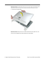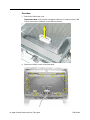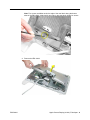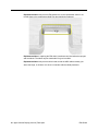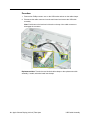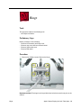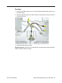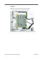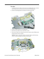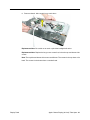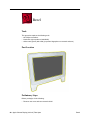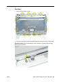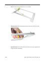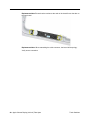
1
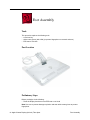
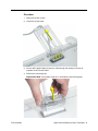
Service Source Apple Cinema Display (20-inch) Updated 13 September 2004 © 2003 Apple Computer, Inc. All rights reserved. Service Source Take Apart Apple Cinema Display (20-inch) © 2003 Apple Computer, Inc. All rights reserved. Tools The following tools are recommended for the take apart procedures. • 2 mm hex key • 2.5 mm hex key • jeweler’s #1 Phillips screwdriver (for backlight bulb tray removal) • #2 Phillips screwdriver • black stick (nylon probe tool 922-5065) • white cotton gloves (922-1592) (to prevent fingerprints on cosmetic surfaces) • ESD wrist strap and mat or soft cloth Important: The display plastics, inside and out, retain fingerprints and can scratch easily. Be very careful with tools, lay the display and plastic parts only on a clean soft surface, and wear clean white cotton gloves when handling and servicing the display. Tools Apple Cinema Display (20-inch) Take Apart - 1 Foot Assembly Tools This procedure requires the following tools: • 2 mm hex key • white cotton gloves (922-1592) (to prevent fingerprints on cosmetic surfaces) • ESD mat or soft cloth Part Location Preliminary Steps Before you begin, do the following: • Place the display face down on an ESD mat or soft cloth Note: Use care to prevent damage to plastics and wear white cotton gloves to prevent fingerprints. 2 - Apple Cinema Display (20-inch) Take Apart Foot Assembly Procedure 1. Remove three hex screws. 2. Lift the foot off the hinge. 3. Pull the ADC (Apple Display Connector) cable through the opening in the foot to separate the foot and the cable. 4. Remove the clear hinge cap. Replacement Note: If the plastic “break-off” is noticeable, install it facing down. Foot Assembly Apple Cinema Display (20-inch) Take Apart - 3 Rear Cover and Rear Cosmetic Shield Tools This procedure requires the following tools: • 2.5 mm hex key • white cotton gloves (922-1592) (to prevent fingerprints on cosmetic surfaces) • ESD mat or soft cloth Note: Use care to prevent damage to plastics and wear white cotton gloves to prevent fingerprints. Preliminary Steps Before you begin, do the following: • Place the display face down on an ESD mat or soft cloth • Remove foot assembly and hinge cover 4 - Apple Cinema Display (20-inch) Take Apart Rear Cover and Rear Cosmetic Shield Procedure 1. Remove twelve hex screws on the rear cover. Replacement Note: The three “shoulder” screws install along the bottom. Replacement Note: Screws are easily stripped; do not overtighten. 2. Lift the rear cover from the top to help disengage it from the tabs on the front legs. Replacement Note: Verify that the USB socket cover is in place, and that the arrowheads on the USB icon point up. Rear Cover and Rear Cosmetic Shield Apple Cinema Display (20-inch) Take Apart - 5 Replacement Note: Install the legs of the rear cover over the legs of the bezel first, then ensure that the seam of the rear cover and bezel seat flush and smooth all around. 3. Remove the cosmetic shield. Replacement Note: Verify that the rear cosmetic shield and the clear plastic rear cover are free of dust, fingerprints and foreign matter before reassembling. 6 - Apple Cinema Display (20-inch) Take Apart Rear Cover and Rear Cosmetic Shield EMI Shield Tools This procedure requires the following tools: • #2 Phillips screwdriver • black stick (nylon probe tool 922-5065) Part Location Preliminary Steps Before you begin, do the following: • Remove foot assembly and hinge cover • Remove rear cover and rear cosmetic shield EMI Shield Apple Cinema Display (20-inch) Take Apart - 7 Procedure 1. Remove the USB socket cover. Replacement Note: Verify that the clear plastic USB cover is in place over the USB socket, and that the arrowheads on the USB icon point up. 2. Remove ten Phillips screws on the EMI shield. 8 - Apple Cinema Display (20-inch) Take Apart EMI Shield Note: Two screws are hidden under the edge of the vent labels along the bottom edge of the EMI shield. A black stick may help to raise the labels slightly for access. 3. Remove the EMI shield. EMI Shield Apple Cinema Display (20-inch) Take Apart - 9 Replacement Note: Verify that the EMI gaskets are on the replacement shield. If not, transfer them to the replacement shield from the shield being replaced. Replacement Note: If replacing the EMI shield, install new vent label adhesive sponges and vent labels. The labels may be transferable if in good condition. Replacement Note: Verify that the ferrite bead around the ADC cable assembly, just above the hinge, is slid down so it does not interfere with the shield placement. 10 - Apple Cinema Display (20-inch) Take Apart EMI Shield USB Cable Assembly Note: The USB cable assembly comes with the USB socket. Tools This procedure requires the following tools: • #2 Phillips screwdriver Preliminary Steps Before you begin, do the following: • Remove foot assembly and hinge cover • Remove rear cover and rear cosmetic shield • Remove USB socket cover • Remove EMI shield USB Cable Assembly Apple Cinema Display (20-inch) Take Apart - 11 Procedure 1. Remove four Phillips screws—two on the USB socket and two on the cable clamps. 2. Disconnect the cable connector from the main board and remove the USB cable assembly. Note: Push down on the back end of the tab on the top of the cable connector to disengage the connector. Replacement Note: Transfer the two identical cable clamps to the replacement cable assembly, if usable, otherwise install new clamps. 12 - Apple Cinema Display (20-inch) Take Apart USB Cable Assembly Hinge Tools This procedure requires the following tools: • #2 Phillips screwdriver Preliminary Steps Before you begin, do the following: • Remove foot assembly and hinge cover • Remove rear cover and rear cosmetic shield • Remove USB socket cover • Remove EMI shield Procedure 1. Remove four Phillips screws. Remove the hinge. Replacement Note: The hinge foot is keyed with three holes that must fit onto pins on the chassis. Hinge Apple Cinema Display (20-inch) Take Apart - 13 ADC Cable Assembly Tools This procedure requires the following tools: • #2 Phillips screwdriver Preliminary Steps Before you begin, do the following: • Remove foot assembly and hinge cover • Remove rear cover and rear cosmetic shield • Remove USB socket cover • Remove EMI shield • Remove hinge 14 - Apple Cinema Display (20-inch) Take Apart ADC Cable Assembly Procedure 1. Remove four Phillips screws—two from the ADC cable hold down block and two from the cable clamps. 2. Disconnect the ADC cable’s one cable connector from the panel, and two connectors from the main board. 3. Remove the ADC cable assembly. Replacement Note: Transfer the two cable clamps to the replacement cable assembly, if usable, otherwise install new clamps. ADC Cable Assembly Apple Cinema Display (20-inch) Take Apart - 15 Main Board Tools This procedure requires the following tools: • #2 Phillips screwdriver • ESD wrist strap Preliminary Steps Before you begin, do the following: • Remove foot assembly and hinge cover • Remove rear cover and rear cosmetic shield • Remove EMI shield Procedure Note: Wear an ESD wrist strap when performing this procedure. 1. Disconnect the cable connectors from the main board. 2. Remove four Phillips screws and remove the board. Replacement Note: Verify notches along board edges align with tabs on chassis. 16 - Apple Cinema Display (20-inch) Take Apart Main Board Inverter Board Tools This procedure requires the following tools: • #2 Phillips screwdriver • ESD wrist strap Preliminary Steps Warning: The inverter board generates high voltage when the display is plugged in. Do not touch the inverter board components, pins or connectors, when the display is connected to the computer. Before you begin, do the following: • Remove foot assembly and hinge cover • Remove rear cover and rear cosmetic shield • Remove EMI shield Inverter Board Apple Cinema Display (20-inch) Take Apart - 17 Procedure Note: Wear an ESD wrist strap when performing this procedure. 1. Disconnect the cable connectors from the inverter board. 2. Remove four Phillips screws and remove the board. Replacement Note: Verify notches along board edges align with tabs on chassis. 18 - Apple Cinema Display (20-inch) Take Apart Inverter Board Display Panel Tools This procedure requires the following tools: • #2 Phillips screwdriver • black stick (nylon probe tool 922-5065) • white cotton gloves (922-1592) (to prevent fingerprints on cosmetic surfaces) Preliminary Steps Before you begin, do the following: • Remove foot assembly and hinge cover • Remove rear cover and rear cosmetic shield • Remove bezel and inner bezel assembly • Remove EMI shield Display Panel Apple Cinema Display (20-inch) Take Apart - 19 Procedure 1. Carefully peel back the adhesive foil that secures the backlight bulb wires, to free the wires and expose the screws that secure the left side of the display panel. 2. Disconnect the backlight bulb wire connectors from the inverter board. 3. Disconnect cable connectors to the display panel. 4. Remove the four Phillips screws located at the corners. 5. Remove two Phillips screws along the top side of the chassis, and two Phillips screws along the bottom side of the chassis. Important: Support underneath the display assembly if lifting it up while removing screws, to prevent the display from falling out of the chassis. 20 - Apple Cinema Display (20-inch) Take Apart Display Panel 6. Remove chassis, being careful not to catch wires. Replacement Note: Be careful not to catch or pinch the backlight bulb wires. Replacement Note: Replace the long corner screws first, before the top and bottom side screws. Note: The top side and bottom side screws are different. The screws for the top have a flat head. The screws for the bottom have a rounded head. Display Panel Apple Cinema Display (20-inch) Take Apart - 21 Bezel Tools This procedure requires the following tools: • #2 Phillips screwdriver • black stick (nylon probe tool 922-5065) • white cotton gloves (922-1592) (to prevent fingerprints on cosmetic surfaces) Part Location Preliminary Steps Before you begin, do the following: • Remove rear cover and rear cosmetic shield 22 - Apple Cinema Display (20-inch) Take Apart Bezel Procedure 1. Remove twelve Phillips screws. 2. Disconnect the power switch and launch switch wire connectors from the inner bezel. Replacement Note: When reattaching the cable connectors, the board will be springy. Verify secure connection. Bezel Apple Cinema Display (20-inch) Take Apart - 23 3. Carefully separate the wire clips enough to remove the wires. 24 - Apple Cinema Display (20-inch) Take Apart Bezel 4. Lift the display assembly from the inner bezel assembly. 5. Locate the bezel (A) and inner bezel (B). Bezel Apple Cinema Display (20-inch) Take Apart - 25 6. To remove the inner bezel from the bezel, start at a corner and lift up on the inner bezel while using a black stick to push in and disengage the bezel clips through the rectangular slots, shown. 7. Lift off the inner bezel. 26 - Apple Cinema Display (20-inch) Take Apart Bezel Note: The bezel cosmetic shield with logo are also removable. Replacement Note: When reassembling the bezel and inner bezel, make sure to snap each bezel clip together. Replacement Note: Verify that the bezel and inner bezel are free of dust, fingerprints and foreign matter before reassembling. Bezel Apple Cinema Display (20-inch) Take Apart - 27 Touch Switches Tools This procedure requires the following tools: • #2 Phillips screwdriver • black stick (nylon probe tool 922-5065) • white cotton gloves (922-1592) (to prevent fingerprints on cosmetic surfaces) Part Location Note: The launch switch board (A) and the power switch board (B) are identical. Preliminary Steps Before you begin, do the following: • Remove bezel Note: If inspecting or replacing the touch switch cables, also remove the EMI shield. 28 - Apple Cinema Display (20-inch) Take Apart Touch Switches Procedure 1. Remove the Phillips screw. Replacement Note: Screws are easily stripped; do not overtighten. Replacement Note: Make sure that the rubber boot is in place on the inner bezel before installing the switch board. Touch Switches Apple Cinema Display (20-inch) Take Apart - 29 Replacement Note: Ensure that the notches at the ends of the board fit onto the tabs on the inner bezel. Replacement Note: When reattaching the cable connector, the board will be springy. Verify secure connection. 30 - Apple Cinema Display (20-inch) Take Apart Touch Switches Service Source Troubleshooting Apple Cinema Display (20-inch) © 2003 Apple Computer, Inc. All rights reserved. Symptom Charts How to Use the Symptom Charts The Symptom Charts included in this chapter will help you diagnose specific symptoms related to the product. Because cures are listed on the charts in the order of most likely solution, try the cures in the order presented. Verify whether or not the product continues to exhibit the symptom. If the symptom persists, try the next cure. Note: If you have replaced a module, reinstall the original module before you proceed to the next cure. Note: Referring to the Block Diagram in this manual may be helpful. Blank screen This symptom may indicate a problem with the LCD panel, inverter board, main board, or related cables or connectors. 1. Check ADC cable. Replace cable if damaged. 2. Check for bent pins in the ADC connector. If pins are slightly bent, carefully straighten. If pins are severely bent, replace cable. Also, inspect or have the customer inspect the display port on the computer for broken pin dividers. If the display port is damaged it must be repaired before inserting the ADC connector. 3. Plug the display into a known-good computer with a known-good video card and ADC display port. Boot the computer and allow enough time to finish booting. 4. If the power button on the display is flashing, two short flashes then a long flash, in a delayed repeating pattern, this indicates trouble with either the inverter board or related cables or connectors. With this in mind, continue with the troubleshooting steps to determine the problem. Symptom Charts Apple Cinema Display (20-inch) - 1 5. To check whether the LCD is working: • Press the launch button on the display which will bring up the Display Preferences window (if the screen is blank you will not see the window). Shine a bright light such as sunlight or a high intensity lamp (see Important note, below) into the screen and at the same time notice whether you can see a faint image of the Display Preferences window or other desktop items on the screen. – If desktop items can be seen, the LCD panel is working. The problem may be with the inverter board or related cables or connectors. Continue with the troubleshooting steps. – If no desktop items can be seen, the problem may be with the LCD panel or the main board or related cables or connectors. Important: Lights get very hot and can quickly damage the display; be extremely careful not to allow too much heat next to the screen or other parts of the display and do not allow the light fixture to touch the screen, or damage can result. 6. Warning: The inverter board generates high voltage when the display is plugged in. Do not touch the inverter board components, pins or connectors, when the display is connected to the computer. Disconnect the display from the computer, then open the display and check for secure connections at TMDS, Panel Power, J1, J2, J3, J4, J6, J7 and J8. Note: Refer to the Block Diagram in this manual for connector locations. 7. Plug the display into a known-good computer, then boot the computer. 8. Connect the ground lead of a volt meter to the metal chassis of the display, then check the following: • At J1, verify +24-28V at pin 1 (pin 4 is ground). If not, replace ADC cable. • At J3, verify +18V at pin 6. If not, replace the main board. • At J4, verify +5V at pin 1. If not, replace the main board. 2 - Apple Cinema Display (20-inch) Symptom Charts Partially dim screen This symptom indicates a problem with the inverter board, LCD panel, or related cables or connectors. 1. Plug the display into a known-good computer with a known-good video card and ADC display port. Boot the computer. 2. Notice whether the power button on the display is flashing, two short flashes then a long flash, in a delayed repeating pattern. This indicates trouble with either the inverter board, LCD panel, or related cables or connectors (this indicator may not always be exhibited). With this in mind, continue with the troubleshooting steps to determine the problem. 3. Warning: The inverter board generates high voltage when the display is plugged in. Do not touch the inverter board components, pins or connectors, when the display is connected to the computer. Disconnect the display from the computer, then open the display and check for secure connections at CN1, CN2, CN3, CN4 and CN5. Note: Refer to the Block Diagram in this manual for connector locations. • If the inverter cable (CN1) is damaged, replace the inverter cable. • If any connectors on the inverter board are damaged, replace the inverter board. • If any of the other CN cables are damaged, replace the LCD panel. Symptom Charts Apple Cinema Display (20-inch) - 3 USB device not working 1. Check for bent pins in the ADC connector. If pins are slightly bent, carefully straighten. If pins are severely bent, replace cable. Also, inspect or have the customer inspect the display port on the computer for broken pin dividers. If the display port is damaged it must be repaired before inserting the ADC connector. 2. Plug the display into a computer with a known-good ADC display port, then boot the computer. On the back of the display, connect a known-good USB device into one of the USB ports, then check Apple System Profiler to see if it is recognized. Check both USB ports. Note: x+R, refreshes the Apple System Profiler list when USB devices are changed. • If the device is recognized, the customer’s USB device may be the issue. • If not, check the J7 and J8 USB connections and cables. If not that, replace the main board. Power switch not working 1. Review Knowledge Base article 58813 to verify that the touch switches have not been disabled. 2. Check J6 and verify that the cable is connected to the power touch switch cable connector. 3. Replace the touch switch. 4. Replace main board. Launch switch not working 1. Review Knowledge Base article 58813 to verify that the touch switches have not been disabled. 2. Check J4 and verify that the cable is connected to the launch touch switch cable connector. 3. Replace the touch switch. 4. Replace main board. 4 - Apple Cinema Display (20-inch) Symptom Charts When displaying a single color over the screen area, the LCD panel shows one or more pixels that are not properly lit Active-matrix LCD technology uses rows and columns of addressable locations (pixels) that render text and images on screen. Each pixel location has three separate subpixels (red, green, and blue) that allow the image to be rendered in full color. Each subpixel has a corresponding transistor responsible for turning the subpixel on or off. There are typically millions of these subpixels on an LCD display. For example, the LCD panel used in the Apple Cinema HD display is made up of 2.3 million pixels and 6.9 million red, green, and blue subpixels. Occasionally, a transistor does not work perfectly, which may result in the affected subpixel being turned on (bright) or turned off (dark). With the millions of subpixels on a display, it is quite possible to have a low number of faulty transistors on an LCD. Therefore, a certain number of subpixel anomalies is considered acceptable. Rejecting all but perfect LCD panels would significantly increase the retail price for products using LCD displays. These factors apply to all manufacturers using LCD technology—not just Apple products. To determine whether or not the display has an acceptable number of pixel anomalies, follow the steps below: 1. Set the display image to one of the following colors: all-white display, all-red display, all-green display, or all-blue display. Note: Knowledge Base article 112125: Service Diagnostics Matrix, has the LCD Tester Diagnostic Utility that will generate these patterns on the screen. 2. Using a jeweler’s loupe, pocket microscope, or other magnifying device, identify and count each subpixel anomaly: • Bright subpixel anomaly = subpixel that is always on • Dark subpixel anomaly = subpixel that is always off 3. Important: Check the number of subpixel anomalies with the following chart: Acceptable Number of Subpixel Anomalies Replace the Display Bright Dark Combination Bright Dark Combination up to 4 up to 6 up to 8 5 or more 7 or more 9 or more 4. If the number of subpixel anomalies exceeds the acceptable number listed in the chart, replace the display panel. 5. If the number of subpixel anomalies is acceptable, explain to the customer that the pixel anomalies are within specifications, and no repair is necessary. Important: Do not release the specifications to customers. Instead, inform them that a certain number of subpixel anomalies is considered acceptable, and these factors apply to all manufacturers using LCD technology—not just Apple products. Symptom Charts Apple Cinema Display (20-inch) - 5 Service Source Views Apple Cinema Display (20-inch) © 2003 Apple Computer, Inc. All rights reserved. Block Diagram Panel Signal Input Backlight Bulb Connectors Main Board Inverter Board Backlight Bulb Connectors USB Socket LCD Display Panel Power On/Off Board Launch Board ADC Cable Apple Cinema Display (20-inch) Views - 1 Exploded View Foot 922-5510 Screw (foot to hinge) 922-5551 Screw (rear cover - top & sides) 922-5601 Screw (rear cover - bottom) 922-5602 Hinge cover 922-5511 Rear cover w/logo 922-5512 Rear cosmetic shield 922-5513 Vent labels (bottom), part of kit 076-0975 USB cover 922-5521 EMI shield 922-5514 Cable (panel to main board) 922-5505 Cable (inverter to main board) 922-5504 Clamp 922-5749 Clamp 922-5792 Vent labels (top), part of kit 076-0975 Adhesive foam for vent labels Screw (chassis to inner bezel) 922-5617 Screw (chassis corners) 922-5619 Chassis 922-5519 Screw (chassis to panel - top side) 922-5618 Screw (hinge to chassis) 922-5620 Hinge 922-5515 Clamp 922-5748 Cable assembly (USB) 922-5509 Clamps 922-5750 Screw (USB socket & cable clamps) 922-5554 Screw (ADC cable hold-down & cable clamps) 922-5554 ADC cable assembly 922-5508 Screw (Main board) 922-5554 Main board 661-2758 Cable (main board to launch button) 922-5506 Cable (main board to power button) 922-5507 Clamp 922-5748 Screw (Inverter board) 922-5554 Inverter board 661-2760 Screw 922-5560 (Chassis to panel - bottom side) Display panel 661-1768 Inner bezel 922-5517 Front logo 922-5522 Boot 922-5541 Touch switch board 922-5530 Screw (Touch switch) 922-5553 Bezel cosmetic shield 922-5518 Bezel 922-5516 2 - Apple Cinema Display (20-inch) Views Screw and Cable Clamp Matrix Apple Cinema Display (20-inch) 922-5551 2.0 mm Hex, 8.8 mm (L) Foot to Hinge(3) 922-5602 2.5 mm Hex, 22 mm (L) Rear Cover - bottom (3) 922-5601 2.5 mm Hex, 15.4 mm (L) Rear Cover - top & sides (9) 922-5619 #2 Phillips, 19.8 mm Chassis corners (4) 922-5618 #2 Phillips (flat-head), 6.2 mm Chassis to panel - top side (2) 922-5560 #2 Phillips (round-head), 5.8 mm Chassis to panel - bottom side (2) #2 Phillips, 5 mm EMI shield to chassis (10) 922-5554 #2 Phillips, 8.2 mm Inverter board (4), main board (4), ADC cable hold down block and cable clamps (4), USB socket and cable clamps (4) 922-5620 #2 Phillips, 8.4 mm Hinge to chassis (4) 922-5617 #2 Phillips, 10.7 mm Inner bezel to chassis (12) 922-5553 #2 Phillips, 7.7 mm Touch switch boards (2) 922-5748 Cable clamp Power switch cable (1) 922-5749 Cable clamp ADC main cable (1) 922-5792 Cable clamp ADC cable to panel (1) 922-5750 Cable clamp USB cable (2)