1
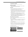
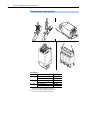
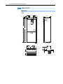
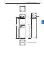
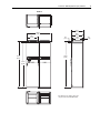
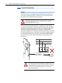
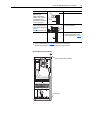
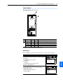
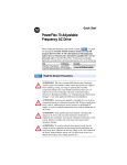
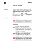
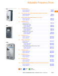
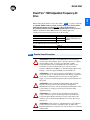
Quick Start PowerFlex 700H Adjustable Frequency AC Drive Title PowerFlex 700H/S Installation Manual PowerFlex Reference Manual PowerFlex 700H/S Hardware Service Manual Publication PFLEX-IN006 PFLEX-RM001 PFLEX-TG001 Available . . . on the CD supplied with the drive or www.rockwellautomation.com/ literature For Allen-Bradley Drives Technical Support: Step 1 Title Online at . . . Allen-Bradley Drives Technical Support www.ab.com/support/abdrives Read the General Precautions ! ! ! ! ! ATTENTION: This drive contains ESD (Electrostatic Discharge) sensitive parts and assemblies. Static control precautions are required when installing, testing, servicing or repairing this assembly. Component damage may result if ESD control procedures are not followed. If you are not familiar with static control procedures, reference A-B publication 8000-4.5.2, “Guarding Against Electrostatic Damage” or any other applicable ESD protection handbook. ATTENTION: An incorrectly applied or installed drive can result in component damage or a reduction in product life. Wiring or application errors, such as, undersizing the motor, incorrect or inadequate AC supply, or excessive ambient temperatures may result in malfunction of the system. ATTENTION: Only qualified personnel familiar with adjustable frequency AC drives and associated machinery should plan or implement the installation, start-up and subsequent maintenance of the system. Failure to comply may result in personal injury and/or equipment damage. ATTENTION: To avoid an electric shock hazard, verify that the voltage on the bus capacitors has discharged before performing any work on the drive. Measure the DC bus voltage at the +DC & –DC terminals (refer to the Installation Manual for location). The voltage must be zero. ATTENTION: Risk of injury or equipment damage exists. DPI host products must not be directly connected together via 1202 cables. Unpredictable behavior can result if two or more devices are connected in this manner. Step 1 When reading this document, look for this symbol “ Step x ” to guide you through the 8 BASIC STEPS needed to install, start-up and program the PowerFlex 700H. The information provided Does Not replace the Installation or Programming Manuals and is intended for qualified drive service personnel only. For detailed PowerFlex 700H information including application considerations and related precautions refer to the following: 2 PowerFlex 700H Adjustable Frequency AC Drive ! ATTENTION: Inputs must be configured with software and jumpers (see page 33). In addition, configuring an analog input for 0-20mA operation and driving it from a voltage source could cause component damage. Verify proper configuration prior to applying input signals. ! ATTENTION: Hazard of personal injury or equipment damage exists when using bipolar input sources. Noise and drift in sensitive input circuits can cause unpredictable changes in motor speed and direction. Use speed command parameters to help reduce input source sensitivity. ! ATTENTION: The “adjust freq” portion of the bus regulator function is extremely useful for preventing nuisance overvoltage faults resulting from aggressive decelerations, overhauling loads, and eccentric loads. It forces the output frequency to be greater than commanded frequency while the drive's bus voltage is increasing towards levels that would otherwise cause a fault. However, it can also cause either of the following two conditions to occur. 1. Fast positive changes in input voltage (more than a 10% increase within 6 minutes) can cause uncommanded positive speed changes. However an “OverSpeed Limit” fault will occur if the speed reaches [Max Speed] + [Overspeed Limit]. If this condition is unacceptable, action should be taken to 1) limit supply voltages within the specification of the drive and, 2) limit fast positive input voltage changes to less than 10%. Without taking such actions, if this operation is unacceptable, the “adjust freq” portion of the bus regulator function must be disabled (see parameters 161 and 162). 2. Actual deceleration times can be longer than commanded deceleration times. However, a “Decel Inhibit” fault is generated if the drive stops decelerating altogether. If this condition is unacceptable, the “adjust freq” portion of the bus regulator must be disabled (see parameters 161 and 162). In addition, installing a properly sized dynamic brake resistor will provide equal or better performance in most cases. Important: These faults are not instantaneous. They can take between 2-12 seconds to occur. EMC Instructions CE Conformity Conformity with the Low Voltage (LV) Directive and Electromagnetic Compatibility (EMC) Directive has been demonstrated using harmonized European Norm (EN) standards published in the Official Journal of the European Communities. PowerFlex Drives comply with the EN standards listed below when installed according to the Installation and Reference Manuals. CE Declarations of Conformity are available online at: http://www.ab.com/certification/ce/docs. PowerFlex 700H Adjustable Frequency AC Drive 3 Low Voltage Directive (73/23/EEC) • EN50178 Electronic equipment for use in power installations. EMC Directive (89/336/EEC) • EN61800-3 Adjustable speed electrical power drive systems Part 3: EMC product standard including specific test methods. General Notes • The motor cable should be kept as short as possible in order to avoid electromagnetic emission as well as capacitive currents. • Use of line filters in ungrounded systems is not recommended. • PowerFlex drives may cause radio frequency interference if used in a residential or domestic environment. The user is required to take measures to prevent interference, in addition to the essential requirements for CE compliance listed below, if necessary. • Conformity of the drive with CE EMC requirements does not guarantee an entire machine or installation complies with CE EMC requirements. Many factors can influence total machine/installation compliance. • PowerFlex drives can generate conducted low frequency disturbances (harmonic emissions) on the AC supply system. More information regarding harmonic emissions can be found in the PowerFlex Reference Manual. Essential Requirements for CE Compliance Conditions 1-6 listed below must be satisfied for PowerFlex drives to meet the requirements of EN61800-3. 1. Standard PowerFlex High Power CE compatible Drive. For Frames 10 and up, the drive must also be installed in a suitable Rittal TS 8 (or equivalent) enclosure. 2. Review important precautions/attention statements throughout this manual before installing the drive. 3. Grounding as described in the PowerFlex High Power Installation Manual. 4. Output power, control (I/O) and signal wiring must be braided, shielded cable with a coverage of 75% or better, metal conduit or equivalent attenuation. 5. All shielded cables should terminate with the proper shielded connector. 6. Conditions in the table below. PowerFlex High Power EN61800-3 EMC Compatibility Frame Second Environment Restrict Motor Cable to 30 m (98 ft.) Any Drive and Option 9 ✔ 10 ✔ 11 ✔ 12 ✔ First Environment Restricted Distribution See PowerFlex Reference Manual 4 PowerFlex 700H Adjustable Frequency AC Drive Step 2 Lift the Drive ! ATTENTION: To guard against possible personal injury and/or equipment damage... • Remove any wiring access covers at the top of the drive (Frame 9). • Do Not allow any part of the drive or lifting mechanism to make contact with electrically charged conductors or components. • At no time should a person or their limbs be directly underneath the items being lifted. • Do not subject the load to high rates of acceleration or deceleration. • Inspect all lifting hardware for proper attachment before lifting drive unit. Frame 9 Important: When lifting the drive, a rod must be placed between the lifting holes as shown below. Frame 9 Weight Weight kg (lbs.) Drive Drive & Packaging 143 (315) 177 (390) PowerFlex 700H Adjustable Frequency AC Drive 5 Frames 10 and Up – Standard Enclosed Drives Step 2 B>A Min. 60˚ To ensure that this angle is greater than 60°, make the length of chain or cable between the center and the corners (B) longer than the distance between the opposite corners (A). A Drive Weights Frame Size Type Frame 10 Drive & Enclosure (AC Input) Drive & Enclosure (DC Input) Frame 11 Drive & Enclosure (AC Input) Drive & Enclosure (DC Input) Frame 12 Drive & Enclosure (AC Input) Drive & Enclosure (DC Input) Weight kg (lbs.) 432 (952) 317 (699) 614 (1350) 446 (980) 802 (1765) 634 (1398) 6 PowerFlex 700H Adjustable Frequency AC Drive Frames 10 and Up – Open Type Drives Drive Weights Frame Size Type Frame 10 Power Structure AC Choke CHK0520 Frame 11 Power Structure AC Choke CHK0400 (1) Frame 12 Power Structure (2) AC Choke (3) (1) (2) (3) Weight kg (lbs.) 120 (265) 115 (254) 210 (463) 84 (185) 120 (265) 84 (185) Two reactors are required per Frame 11 AC Drive Two power structures are required per Frame 12 Drive Two reactors are required per Frame 12 AC Drive PowerFlex 700H Adjustable Frequency AC Drive 7 Removing the Skid and Shipping Feet ! Task A B C D ATTENTION: To guard against personal injury and equipment damage, do not work under the drive unless the drive is securely mounted on appropriate blocks. Description Using a 15 mm wrench, remove the hardware which secures the drive to the skid. Lift the drive off the skid. Place the drive on proper blocks on a hard level surface. The blocks should be approximately 10 cm (4 inches) high. Using a 17 mm wrench, remove the hardware which secures the feet to the drive and remove the feet. A B A C A D C D D 8 PowerFlex 700H Adjustable Frequency AC Drive Step 3 Mount the Drive Dimensions Frame 9 480.0 (18.90) 5.0 (0.20) 14.0 (0.55) 400.0 (15.75) 240.0 (9.45) 363.3 (14.32) 339.5 (13.37) 9.0 (0.35) 45.0 (1.77) Nameplate Wire Way 1150.0 (45.28) 1120.0 (44.09) Nameplate 9.0 (0.35) Lifting Hole 21.0 (0.83) 372.5 (14.67) 292.5 (11.52) 142.5 (5.61) 62.5 (2.46) 245.53 (9.67) 59.0 (2.32) 191.64 (7.54) 100.12 (3.94) 285.0 (11.22) Detail A Brake Option Top Hat PowerFlex 700H Adjustable Frequency AC Drive 9 Frame 10 632.5* (24.90) 597.0 (23.50) 534.7 (21.05) 605.5 (23.84) 32.3 (1.27) 498.0 (19.61) 42.0 (1.65) Step 3 2234.0 (87.95) 2275.0 (89.57) 2201.8 (86.68) * This dimension is the depth for drives with the optional door-mounted HIM installed 10 PowerFlex 700H Adjustable Frequency AC Drive Frame 11 ! 797.0 (31.38) 621.74* (24.48) 736.0 (28.98) 605.5 (23.84) 32.25 (1.27) 498.0 (19.61) DANGER 2234.0 (87.95) 2275.0 (89.57) 2205.0 (86.81) * This dimension is the depth for drives with the optional door-mounted HIM installed 42.0 (1.65) PowerFlex 700H Adjustable Frequency AC Drive 11 Frame 12 632.5* (24.90) 1196.05 (47.09) 534.7 (21.05) 605.5 (23.84) 32.3 (1.27) 498.0 (19.61) 2234.0 (87.95) 2275.0 (89.57) 2201.8 (86.68) * This dimension is the depth for drives with the optional door-mounted HIM installed 42.0 (1.65) 12 PowerFlex 700H Adjustable Frequency AC Drive Minimum Mounting Clearances Frame 9 400.0 mm (15.75 in.) 400.0 mm (15.75 in.) 50.0 mm (1.97 in.) 50.0 mm (1.97 in.) 80.0 mm (3.2 in.) 350.0 mm (13.8 in.) 350.0 mm (13.8 in.) Frame 10 200 mm (7.87 in.) 800 mm (31.50 in.) PowerFlex 700H Adjustable Frequency AC Drive Frame 11 200 mm (7.87 in.) 1000 mm (39.3 in.) 13 14 PowerFlex 700H Adjustable Frequency AC Drive Frame 12 200 mm (7.87 in.) 800 mm (31.50 in.) Operating Temperatures Surrounding Air Temperature Frame Normal Duty 9 0 to 40 degrees C (32 to 104 degrees F) 10 0 to 40 degrees C (32 to 104 degrees F) 11 0 to 40 degrees C (32 to 104 degrees F) 12 0 to 40 degrees C (32 to 104 degrees F) Heavy Duty 0 to 50 degrees C (32 to 122 degrees F) 0 to 40 degrees C (32 to 104 degrees F) 0 to 40 degrees C (32 to 104 degrees F) 820A & 920A 0 to 40 degrees C Drives (32 to 104 degrees F) 1030A Drives 0 to 35 degrees C (32 to 95 degrees F) Notes Drive requires a minimum of 1300 m3/h (765 cfm) of cooling air. Drive requires a minimum of 2600 m3/h (1530 cfm) of cooling air. Drive requires a minimum of 3900 m3/h (2295 cfm) of cooling air. Drive requires a minimum of 5200 m3/h (3060 cfm) of cooling air. Drive requires a minimum of 5200 m3/h (3060 cfm) of cooling air. PowerFlex 700H Adjustable Frequency AC Drive 15 Mounting Floor Only Mounting Secure drive to the floor with anchor bolts in the front corner holes of the enclosure base plate. Additionally secure the drive using the mounting plates as needed (Rittal part no. 8800-210 or equivalent). Do this as far back as possible to the choke assembly plate. With this method the holes through base plate must be drilled on-site. Important: If it is important to align the drive cabinet vertically with adjacent Rittal cabinets, you may need to place shims under the drive cabinet or use leveling feet throughout the cabinet line-up. The Allen-Bradley factory may have removed the standard plastic plugs from the bottom of the cabinet when installing the shipping feet. This reduces the height of the cabinet by 2.0 mm (0.08 in.). Wall Mounting Secure drive to the floor with anchor bolts in the front corner holes of the enclosure base plate. Secure the drive by bolting the adjustable lifting rails to the rear wall or supporting structure. Wall 16 PowerFlex 700H Adjustable Frequency AC Drive Step 4 Check the Ground System Frame 9 CE Frame 9 drives are equipped with common mode capacitors that are referenced to ground. Operating a CE frame 9 drive on an ungrounded distribution system could result in drive damage. ! ATTENTION: If you intend to operate a Frame 9 drive on an ungrounded distribution system, you must order a non-CE PowerFlex High Power drive. All Frame 9 drives (CE and non-CE) are equipped with a Metal Oxide Varistor assembly (MOV) to provide voltage surge protection. The MOV is designed for transient surge suppression only (not continuous operation). With an ungrounded distribution system the phase-to-ground MOV connection could become a continuous current path. Therefore, you should disconnect the MOV ground connection when installing a Frame 9 drive on an ungrounded distribution system. Refer to publication PFLEX-RM001, PowerFlex Reference Manual, for information on ungrounded system installation. L1 L2 L3 Disconnect and Insulate this Wire on Ungrounded Systems ! Ground Stud on Cross Plate ATTENTION: Risk of equipment damage exists if this wire contacts other circuits in the drive while the drive is energized. Insulate the lug on this wire with several turns of electrical tape and anchor the wire so it does not contact other circuits. PowerFlex 700H Adjustable Frequency AC Drive 17 Frames 10 and Up Frames 10 and up are equipped with common mode capacitors that are referenced to ground. To guard against drive damage, these capacitors should be disconnected if the drive is installed on an ungrounded distribution system. To disconnect the capacitors, move the jumper shown below. Refer to publication PFLEX-RM001, PowerFlex Reference Manual, for information on ungrounded system installation. There is one jumper on each Rectifying Module. Frame Size 10 11 12 (1) Number of Rectifying Modules (Number of Jumpers) Location of Rectifying Module(s) 1 Upper-right side of drive power structure. 2 (1) Center and right hand power stacks of drive power structure. 2 (1) Upper-right side of each power structure. Jumpers on both rectifying modules must be in the same position. Figure 1.1 Moving Common Mode Capacitor Jumper Task A B C D Description Loosen upper screw. Remove lower screw. Move jumper to horizontal position. Install and tighten screws. C B Rectifying Circuit Board Step 4 D A 18 PowerFlex 700H Adjustable Frequency AC Drive Step 5 Power Wiring Most start-up difficulties are the result of incorrect wiring. Every precaution must be taken to assure that the wiring is done as instructed. All items must be read and understood before the actual installation begins. ATTENTION: The following information is merely a guide for proper installation. Rockwell Automation, Inc. cannot assume responsibility for the compliance or the noncompliance to any code, national, local or otherwise for the proper installation of this drive or associated equipment. A hazard of personal injury and/or equipment damage exists if codes are ignored during installation. ! Frame 9 Cover Removal (8 Screws) (3 Screws) L1 L2 L3 L1 L2 L3 U/T1 V/T2 W/T3 U/T1 V/T2 W/T3 (8 Screws) PowerFlex 700H Adjustable Frequency AC Drive 19 Frame 9 Terminal Locations ➌ ➍ DC – DC +/R + R– ➋ ➊ ➌ ➎ Figure 1 Power Terminal Block (1) L1 L2 L3 L1 L2 L3 U/T1 V/T2 W/T3 U/T1 V/T2 W/T3 To Motor Leads Step 5 AC Line Input Power Frame 9 Power Terminal Specifications Wire Size Range (3) Maximum Minimum 185.0 mm2 95.0 mm2 (350 MCM) (4/0 AWG) 185.0 mm2 95.0 mm2 (350 MCM) (4/0 AWG) Torque Recommended 40 N-m (354 lb.-in.) 40 N-m (354 lb.-in.) No. Name ➊ Input Power Terminal Block (1) L1, L2, L3 ➋ Output Power Terminal Block (1) U/T1, V/T2, W/T3 Description Input power ➌ SHLD Terminal, PE, Motor Terminating point for wiring shields 95.0 mm2 (4/0 AWG) 5.0 mm2 (10 AWG) 22 N-m (195 lb.-in.) 185.0 mm2 (350 MCM) 185.0 mm2 (350 MCM) 95.0 mm2 (4/0 AWG) 95.0 mm2 (4/0 AWG) 40 N-m (354 lb.-in.) 40 N-m (354 lb.-in.) Ground ➍ DC Bus (2) Motor connections DC input or external brake (2 Terminals; DC–, DC+) (Internal Brake option not ordered) DC Bus w/Brake (2) DC input/internal brake (3 Terminals; DC–, DC+/R+, R–) (Internal Brake option is ordered) ➎ Cable Clamp for Strain Relief (1) (2) (3) Do Not exceed maximum wire size. Parallel connections may be required. DC terminal and brake lugs can be removed. Maximum/minimum sizes that the terminal block will accept - these are not recommendations. 20 PowerFlex 700H Adjustable Frequency AC Drive Frame 10 Cover Removal Moving Control Frame To gain access to the airflow plate and protective covers you must move the Control Frame out of the way. Task A B Description Remove the T8 Torx-head screws which secure the Control Frame to the drive enclosure. Swing the Control Frame out and away from the power structure. A A B Removing the Airflow Plate The drive is equipped with a plate, just above the Control Frame, that manages airflow through the drive. You must remove this plate in order to access the protective covers. Task C D Description Remove the T8 Torx-head screws which secure the airflow plate to the drive. Slide airflow plate off of drive. C C D PowerFlex 700H Adjustable Frequency AC Drive 21 Removing Protective Covers You must remove the protective covers to gain access to the power structure. Task E F G H (1) Description Remove the four M5 Pozi-drive screws which secure the top and bottom protective covers to the main front protective cover, then remove the top and bottom protective covers. Remove the four M4 Pozi-drive screws which secure the side protective covers to the main front protective cover(1). Remove the four M5 Pozi-drive screws which secure the main front protective cover to the drive, then remove the protective cover. Remove side protective covers. In some configurations these screws will not be present Important: The side protective covers are not reversible, make note of which is left and which right. E H E H F G E E 22 PowerFlex 700H Adjustable Frequency AC Drive ➍ Frame 10 Terminal Locations DC+/R+ DCR- V/T2 ➋ ➌ ➊ U/T1 W/T3 L1 L2 L3 ➎ Frame 10 Power Terminal Specifications Wire Size Range (1)(2) Maximum Minimum 300 mm2 2.1 mm2 (600 MCM) (14 AWG) 300 mm2 2.1 mm2 (600 MCM) (14 AWG) No. Name Terminal Block ➊ Input Power L1, L2, L3(3) ➋ Output Power Terminal Block (3) U/T1, V/T2, W/T3 Description Input power PE, Motor ➌ SHLD Terminal, (3) 2.1 mm2 Terminating point for wiring shields 300 mm2 (600 MCM) (14 AWG) Ground ➍ DC Bus (3) Motor connections DC input or external brake (2 Terminals; DC–, DC+) (Internal Brake option not ordered) DC input/internal brake DC Bus w/Brake (3) (3 Terminals; DC–, DC+/R+, R–) (Internal Brake option is ordered) 300 mm2 (600 MCM) 300 mm2 (600 MCM) 2.1 mm2 (14 AWG) 2.1 mm2 (14 AWG) Torque Recommended 40 N-m (354 lb.-in.) 40 N-m (354 lb.-in.) Terminal Bolt Size(3) (4) M12 40 N-m (354 lb.-in.) M10 40 N-m (354 lb.-in.) 40 N-m (354 lb.-in.) M12 M12 M12 ➎ Cable Clamp for Strain Relief (1) (2) (3) (4) Maximum/minimum sizes that the terminal block will accept - these are not recommendations. Do Not exceed maximum wire size. Parallel connections may be required. These connections are bus bar type terminations and require the use of lug type connectors. Apply counter torque to the nut on the other side of terminations when tightening or loosening the terminal bolt in order to avoid damage to the terminal. PowerFlex 700H Adjustable Frequency AC Drive 23 Frame 11 Cover Removal Moving Control Frame To gain access to the airflow plate and protective covers you must move the Control Frame out of the way. Task A B Description Loosen the T8 Torx-head screws which secure the Control Frame to the drive enclosure. Swing the Control Frame out and away from the power structure. A A B Removing the Airflow Plate The drive is equipped with a plate, just above the Control Frame, that manages airflow through the drive. You must remove this plate in order to access the protective covers. Task C D Description Remove the T8 Torx-head screws which secure the airflow plate to the drive. Slide airflow plate off of drive. C D C 24 PowerFlex 700H Adjustable Frequency AC Drive Removing Protective Covers You must remove the protective covers to gain access to the power structure. Task E F Description Remove the four M5 Pozi-drive screws which secure the top and bottom protective covers to the main front protective cover, then remove the top and bottom protective covers. Remove the four M5 Pozi-drive screws which secure the main front protective cover to the drive, then remove the protective cover. E ! DA Risk of electri Discon NG ER verify nect c shock FollowDC power and bus , wait death. Earth instruc voltag 5 minute groun tions e before d requirin s manua servicand ed. l beforeing. use. F 400 and 480 Volt AC Input Wiring for Frame 11 Drives Frame 11 drives with 400V and 480V ac input power utilize two parallel input rectifying modules, and therefore have two sets of AC input power terminals. You must supply power to both sets of input terminals. There are several methods for accomplishing this. Important: Parallel wiring must have the same cable dimensions, type and routing. Non-symmetrical wiring may cause unequal loading between the converters and reduce the drive’s ability to deliver current to the motor. Frame 11 AC Wiring Examples 2 Fuses per Phase L1 1L1 1L2 1L3 1 Fuse per Phase L2 L3 L1 2L1 2L2 2L3 1L1 1L2 1L3 L2 L3 2L1 2L2 2L3 PowerFlex 700H Adjustable Frequency AC Drive Frame 11 Terminal Locations ➍ DC+ DC- ➋ ➌ U/T1 1L1 V/T2 1L3 1L2 ➊ W/T3 2L1 2L3 2L2 ➎ Frame 11 Power Terminal Block Specifications No. Name Description ➊ Input Power Terminal Block (3) AC Input power 1L1, 1L2, 1L3, 2L1, 2L2, 2L3 ➋ Output Power Terminal Block ((3) Motor connections U/T1, V/T2, W/T3 Wire Size Range (1)(2) Maximum Minimum 2.1 mm2 300 mm2 (600 MCM) (14 AWG) 300 mm2 2.1 mm2 (600 MCM) (14 AWG) Torque Recommended 40 N-m (354 lb.-in.) 40 N-m (354 lb.-in.) Terminal Bolt Size(3) (4) M12 M12 PE, Motor ➌ SHLD Terminal, (3) Terminating point for wiring shields 300 mm2 2.1 mm2 (600 MCM) (14 AWG) 40 N-m (354 lb.-in.) M10 ➍ DC Bus (3) DC input or external brake 300 mm2 2.1 mm2 (Internal Brake option not ordered) (600 MCM) (14 AWG) 40 N-m (354 lb.-in.) M12 Ground (2 Terminals; DC–, DC+) ➎ Cable Clamp for Strain Relief (1) (2) (3) (4) Maximum/minimum sizes that the terminal block will accept - these are not recommendations. Do Not exceed maximum wire size. Parallel connections may be required. These connections are bus bar type terminations and require the use of lug type connectors. Apply counter torque to the nut on the other side of terminations when tightening or loosening the terminal bolt in order to avoid damage to the terminal. 25 26 PowerFlex 700H Adjustable Frequency AC Drive Frame 12 Cover Removal Moving Control Frame To gain access to the airflow plate and protective covers you must move the Control Frame out of the way. Task A B Description Loosen the T8 Torx-head screws which secure the Control Frame to the drive enclosure. Swing the Control Frame out and away from the power structure. A A B Removing the Airflow Plate The drive is equipped with a plate, just above the Control Frame, that manages airflow through the drive. You must remove this plate in order to access the protective covers. Task C D Description Remove the T8 Torx-head screws which secure the airflow plate to the drive. Slide airflow plate off of drive. C D C PowerFlex 700H Adjustable Frequency AC Drive 27 Removing Protective Covers You must remove the protective covers to gain access to the power structure. Task E Description Remove the four M5 Pozi-drive screws which secure the top and bottom protective covers to the main front protective cover, then remove the top and bottom protective covers. Note: Power terminal access is gained by removing the top and bottom covers only. Remove the four M5 Pozi-drive screws which secure the main front protective cover to the drive, then remove the protective cover. Remove side protective covers. F G Important: The side protective covers are not reversible, make note of which is left and which right. E G E G F E E 28 PowerFlex 700H Adjustable Frequency AC Drive Input Power Wiring Frame 12 drives utilize two parallel power structures, and therefore have two sets of input power terminals. You must supply power to both sets of input terminals. Important: Parallel wiring must have the same cable dimensions, type and routing. Non-symmetrical wiring may cause unequal loading between the converters and reduce the drive’s ability to deliver current to the motor. Frame 12 Input Wiring Examples 2 Fuses per Phase L1 1 Fuse per Phase L3 L1 2L1 2L2 2L3 1L1 1L2 1L3 L2 1L1 1L2 1L3 L2 L3 2L1 2L2 2L3 Output Power Wiring Frame 12 drives utilize two parallel power structures, and therefore have two sets of output power terminals. You must connect the motor to both sets of input terminals. Refer to the “Important” statement above. Important: The minimum cable length for parallel motor cables from the drive to the point where the cables connect is 5m (16.4 ft). Join the parallel cables at the motor end (not the drive end). Frame 12 Output Wiring Example 1T1 1T2 1T3 PE 2T1 2T2 2T3 PE Motor Motor Frame PowerFlex 700H Adjustable Frequency AC Drive 29 Frame 12 Power Terminal Specifications Wire Size Range (1)(2) Maximum Minimum 2.1 mm2 300 mm2 (600 MCM) (14 AWG) 300 mm2 2.1 mm2 (600 MCM) (14 AWG) No. Name ➊ Input Power Terminal Block (3) 1L1, 1L2, 1L3, 2L1, 2L2, 2L3 ➋ Output Power Terminal Block (3) 1U/1T1, 1V/1T2, 1W/1T3, 2U/2T1, 2V/2T2, 2W/2T3 Description Input power PE, Motor ➌ SHLD Terminal, (3) Terminating point for wiring shields 300 mm2 2.1 mm2 (600 MCM) (14 AWG) Ground Motor connections ➍ DC Bus (3) DC input or external brake (2 Terminals; DC–, DC+) (Internal Brake option not ordered) DC Bus w/Brake (3) DC input/internal brake (3 Terminals; DC–, DC+/R+, R–) (Internal Brake option is ordered) 300 mm2 (600 MCM) 300 mm2 (600 MCM) 2.1 mm2 (14 AWG) 2.1 mm2 (14 AWG) Torque Recommended 40 N-m (354 lb.-in.) 40 N-m (354 lb.-in.) Terminal Bolt Size(3) (4) M12 40 N-m (354 lb.-in.) M10 40 N-m (354 lb.-in.) 40 N-m (354 lb.-in.) M12 M12 M12 ➎ Cable Clamp for Strain Relief (1) (2) (3) (4) Maximum/minimum sizes that the terminal block will accept - these are not recommendations. Do Not exceed maximum wire size. Parallel connections may be required. These connections are bus bar type terminations and require the use of lug type connectors. Apply counter torque to the nut on the other side of terminations when tightening or loosening the terminal bolt in order to avoid damage to the terminal. Frame 12 Terminal Locations ➍ ➍ DC- DC+ ➋ DC- DC+ 1V/T2 2V/T2 Cat No. FIELD INSTALLED OPTIONS: DC BUS CONDUCTORS AND CAPACITORS OPERATE AT HIGH VOLTAGE. REMOVE POWER OPERATE AT HIGH VOLTAGE. REMOVE POWER AND WAIT 5 MINUTES BEFORE SERVICING AND WAIT 5 MINUTES BEFORE SERVICING 1U/T1 1W/T3 1L1 1L2 ➊ 1L3 ➋ DANGER DANGER DC BUS CONDUCTORS AND CAPACITORS 2U/T1 2L1 2L2 2L3 ➊ ➎ ➌ 2W/T3 ➎ 30 PowerFlex 700H Adjustable Frequency AC Drive Step 6 Signal and Control Wiring Important points to remember about I/O wiring: • Always use copper wire. • Wire with an insulation rating of 600V or greater is recommended. • Control and signal wires should be separated from power wires by at least 0.3 meters (1 foot). Important: I/O terminals labeled “(–)” or “Common” are not referenced to earth ground and are designed to greatly reduce common mode interference. Grounding these terminals can cause signal noise. ! ATTENTION: Inputs must be configured with software and jumpers (see page 33). In addition, configuring an analog input for 0-20mA operation and driving it from a voltage source could cause component damage. Verify proper configuration prior to applying input signals. ! ATTENTION: Hazard of personal injury or equipment damage exists when using bipolar input sources. Noise and drift in sensitive input circuits can cause unpredictable changes in motor speed and direction. Use speed command parameters to help reduce input source sensitivity. Wire Types Recommended Signal Wire Signal Type Analog I/O Wire Type(s) Description Belden 8760/9460(or equiv.) 0.750 mm2 (18AWG), twisted pair, 100% shield with drain (1). Belden 8770(or equiv.) 0.750 mm2 (18AWG), 3 cond., shielded for remote pot only. EMC Compliance Refer to “EMC Instructions” on page 2 for details. (1) Minimum Insulation Rating 300V, 75-90 degrees C (167-194 degrees F) If the wires are short and contained within a cabinet which has no sensitive circuits, the use of shielded wire may not be necessary, but is always recommended. Recommended Control Wire for Digital I/O Type Unshielded Shielded Wire Type(s) Per US NEC or applicable national or local code Multi-conductor shielded cable such as Belden 8770(or equiv.) Description – 0.750 mm2 (18AWG), 3 conductor, shielded. Minimum Insulation Rating 300V, 60 degrees C (140 degrees F) PowerFlex 700H Adjustable Frequency AC Drive 31 I/O Terminal Blocks and Jumpers J5 J3 & J4 J1 & J2 ➊ ➋ ➌ I/O Terminal Block Specifications No. Name ➊ Analog I/O Description Analog I/O Signals ➋ Digital Inputs Digital Input Signals ➌ Digital Outputs Digital Out Relays (1) Wire Size Range (1) Maximum Minimum 0.5 mm2 2.5 mm2 (14 AWG) (22 AWG) 2.5 mm2 0.5 mm2 (14 AWG) (22 AWG) 2.5 mm2 0.5 mm2 (14 AWG) (22 AWG) Torque Maximum 0.2 N-m 1.8 lb.-in. 0.2 N-m 1.8 lb.-in. 0.5 N-m 4.5 lb.-in. Recommended 0.2 N-m 1.8 lb.-in. 0.2 N-m 1.8 lb.-in. 0.5 N-m 4.5 lb.-in. Maximum/minimum that the terminal block will accept - these are not recommendations. Step 6 PowerFlex 700H Adjustable Frequency AC Drive 1 10 20 No. 1 2 3 4 Signal Analog In 1 (–) (1) Analog In 1 (+) (1) Analog In 2 (–) (1) Analog In 2 (+) (1) 5 –10V Pot Reference – 6 7 Pot Common (GND) +10V Pot Reference – 8 Analog Out 1 (+) 9 Analog Out Common 10 Analog Out 2 (+) (4) 11 12 13 14 Stop - CF Start Auto/Man Speed Sel 1 Speed Sel 2 Speed Sel 3 Digital In 1 Digital In 2 Digital In 3 Digital In 4 15 Digital In 5 16 Digital In 6/Hardware Enable, see pg. 33 17 Digital In Common 18 21 (1) (2) (3) (4) (5) (4) 19 20 21 22 23 24 25 26 +24VDC (2) 24V Common (2) Digital Out 1 – N.C. (3) Digital Out 1 Common Digital Out 1 – N.O. (3) Digital Out 2 – N.C. (3) Digital Out 2/3 Com. Digital Out 3 – N.O. (3) – – Fault NOT Fault NOT Run Description Isolated (5), bipolar, differential, 9 bit & sign, 88k ohm input impedance. A jumper (page 33) selects: 0-10V, ±10V, 4-20mA. Default: 0-10V (Ri =200k), 4-20mA (Ri=100 ohm). 2k ohm minimum, 10 mA maximum load, 1% accuracy. For (+) and (–) 10V pot references. 2k ohm minimum, 10mA maximum load, 1% accuracy. Bipolar (current out is not bipolar), 9 bit & sign, 2k ohm minimum load. A jumper (see page 33) selects: 0-10V, ±10V, 4-20mA. 115V ac, 50/60 Hz - Opto isolated Low State: less than 30V ac High State: greater than 40V ac 24V dc - Opto isolated (250V) Low State: less than 5V dc High State: greater than 20V dc 11.2 mA DC Enable: Digital Input 6 is jumper selectable for HW Enable. On-Time: < 16.7ms, Off-Time < 1ms Allows source or sink operation. Terminals 17/18 & 19 can also be used to provide backup power to DPI and control devices. Drive supplied logic input power. Common for internal power supply. Max. Resistive Load: 240V ac/30V dc – 1200VA, 150W Max. Current: 5A, Min. Load: 10mA Max. Inductive Load: 240V ac/30V dc – 840VA, 105W Max. Current: 3.5A, Min. Load: 10mA Related Parameter(s) I/O Terminal Designations Factory Default 32 320 327 340 347 361 366 380 391 Run Important: Input must be configured with a jumper. Drive damage may occur if jumper is not installed properly. Refer to page 33. 150mA maximum Load. Not present on 115V versions. Can be used to provide control power from an external 24V source when main power is not applied. Refer to page 33 Contacts in un-powered state. Any relay programmed as Fault or Alarm will energize (pick up) when power is applied to drive and de-energize (drop out) when a fault or alarm exists. Relays selected for other functions will energize only when that condition exists and will de-energize when condition is removed. These inputs/outputs are dependant on a number of parameters (see “Related Parameters”). Differential Isolation - External source must be maintained at less than 160V with respect to PE. Input provides high common mode immunity. PowerFlex 700H Adjustable Frequency AC Drive 33 Analog I/O Configuration Important: Analog I/O must be configured through programming, as well as the jumpers shown below. I/O Configuration Signal Analog Inputs Jumper J1 (Analog In 1) J2 (Analog In 2) Analog Outputs Setting 0-20 mA ±10V 0-10V J1 J2 J1 A B C D A B C D A B C D J3 (Analog Out 1) 0-20 mA J4 (Analog Out 2) J3 A B C D J2 J1 J2 A B C D A B C D A B C D ±10V 0-10V J4 J3 J4 J3 J4 A B C D A B C D A B C D A B C D A B C D Hardware Enable Circuitry By default, the user can program a digital input as an Enable input. The status of this input is interpreted by drive software. If the application requires the drive to be disabled without software interpretation, a “dedicated” hardware enable configuration can be utilized. This is done by removing jumper J5 and wiring the enable input to “Digital In 6” (see below). Verify that [Digital In6 Sel], parameter 366 is set to “1, Enable.” Hardware Enable Configuration Signal Jumper Hardware J5 Enable Setting Hardware Enable Input Programmable (No Hardware Enable) J5 J5 A B A B Auxiliary Power Supply You may use an auxiliary power supply to keep the 700H Control Unit energized, when input power is de-energized. This provides back-up power for the Control Unit and is sufficient for setting parameters. Connect 24V dc power to pin 19 and 24V dc common to pin 20 of the 24V dc version of the I/O card. Auxiliary Power Supply Specifications Voltage 24V dc ± 15% Current (Min) 150 mA Current (Max) 250 mA If 24V terminals of several drives are connected in parallel, we recommend using a diode circuit to block current flow in the opposite direction. Reverse current flow could damage the Control Board. From Auxiliary Power Supply 24V dc Power 19 24V dc Common 20 19 20 19 20 19 20 34 PowerFlex 700H Adjustable Frequency AC Drive I/O Wiring Examples Input/Output Potentiometer Unipolar Speed Reference (1) 10k Ohm Pot. Recommended (2k Ohm Minimum) Connection Example 3 4 6 6 7 Joystick Bipolar Speed Reference (1) ±10V Input 3 4 5 6 7 Analog Input Bipolar Speed Reference ±10V Input 3 4 Analog Voltage Input Unipolar Speed Reference 0 to +10V Input 3 4 Analog Current Input Unipolar Speed Reference 4-20 mA Input Analog Output ±10V, 4-20 mA Bipolar +10V Unipolar (shown) + 2-Wire Control Non-Reversing(2) 24V dc internal supply 8 9 12 17 19 20 Stop-Run 2-Wire Control Reversing(2) External supply (I/O Board dependent) 115V/ +24V Run Fwd. 11 12 Run Rev. Neutral/ Common 3-Wire Control Internal supply • Set I/O configuration (see page 33). • Set Direction Mode: Parameter 190 = “1, Bipolar” • Adjust Scaling: Parameters 91/92 and 325/326 • View Results: Parameter 002 • Set I/O configuration (see page 33). • Set Direction Mode: Parameter 190 = “1, Bipolar” • Adjust Scaling: Parameters 91/92 and 325/326 • View Results: Parameter 002 • Set I/O configuration (see page 33). • Configure Input with parameter 320 • Adjust Scaling: Parameters 91/92 and 325/326 • View results: Parameter 002 • Set I/O configuration (see page 33). • Configure Input for Current: Parameter 320 and add jumper at appropriate terminals • Adjust Scaling: Parameters 91/92 and 325/326 • View results: Parameter 002 • Set I/O configuration (see page 33). • Configure with Parameter 340 • Select Source Value: Parameter 384, [Digital Out1 Sel] • Adjust Scaling: Parameters 343/344 3 4 – Required Parameter Changes • Set I/O configuration (see page 33). • Adjust Scaling: Parameters 91/92 and 325/326 • View Results: Parameter 002 • Disable Digital Input #1: Parameter 361 = “0, Unused” • Set Digital Input #2: Parameter 362 = “7, Run” • Set Direction Mode: Parameter 190 = “0, Unipolar” • Set Digital Input #1: Parameter 361 = “8, Run Forward” • Set Digital Input #2: Parameter 362 = “9, Run Reverse” 17 Stop • No Changes Required 11 12 Start 17 19 20 PowerFlex 700H Adjustable Frequency AC Drive Input/Output Connection Example 3-Wire Control 115V/ +24V Stop External supply 11 12 (I/O Board dependent). Start Requires 3-wire functions Neutral/ only ([Digital In1 Sel]). 17 Common Using 2-wire selections will cause a type 2 alarm. Required Parameter Changes • No Changes Required Digital Output Relays shown in powered state with drive faulted. See page 32. 2 relays at terminals 24-26. • Select Source to Activate: Parameters 380/384 Power Source or 21 22 23 24 25 26 Fault NOT Fault NOT Run Run • Configure with parameter 366 For dedicated hardware Enable: Remove Jumper J5 (see page 33) Enable Input 16 (1) (2) 35 Refer to the Attention statement on page 30 for important bipolar wiring information. Important: Programming inputs for 2 wire control deactivates all HIM Start buttons. I/O and Communication Wire Routing Network Communication Cabling Control Wiring 36 PowerFlex 700H Adjustable Frequency AC Drive Step 7 Start-Up Check List ❏ 1. Verify supply voltage. L1 V L2 L3 ❏ 2. Check power wiring. U V W PE ❏ 3. Check control wiring. ❏ 4. Apply AC power and control voltages to the drive. If any of the six digital inputs are configured to “Stop – CF” (CF = Clear Fault) or “Enable,” verify that signals are present or reconfigure [Digital Inx Sel]. If an I/O option is not installed (i.e. no I/O terminal block), verify that [Digital Inx Sel] is not configured to “Stop – CF” or “Enable.” If this is not done, the drive will not start. Refer to Troubleshooting – Abbreviated Fault & Alarm Listing on page 44 for a list of potential digital input conflicts. If the STS LED is not flashing green at this point, see page 37. ❏ 5. Select Start-Up method: SMART Start . . . 1. Press ALT and then Esc (S.M.A.R.T). The S.M.A.R.T. start screen appears. 2. View and change parameter values as desired. For HIM information, refer to the Programming Manual. 3. Press Esc to exit the S.M.A.R.T. start. Esc ALT F-> Stopped Esc or any of the other start-up routines . . . F-> Stopped 0.0 Hz Main Menu: Memory Storage Start Up Preferences Auto 0.0 Hz Auto SMART List: Main Menu:In2 Sel Digital Diagnostics Stop Mode A Parameter Minimum Speed PowerFlex 700H Adjustable Frequency AC Drive 37 Status Indicators Drive Status Indicators (Frame 9 Shown) ➊ ➋ # Name PWR (Power) Color Green State Steady Description Illuminates when power is applied to the drive. MOD (1) NET A (1) NET B (1) Green Yellow Red Red – – – – Status of DPI port internal communications (if present). Status of communications module (when installed). Status of network (if connected). Status of secondary network (if connected). ➊ ➋ PORT (1) (1) Refer to the Communication Option User Manual for details. HIM Indication The LCD HIM also provides visual notification of a fault or alarm condition. Display F-> Faulted Auto 0.0 Hz — Fault — F Main Menu: OverVoltage Diagnostics Time Since Fault 0000:23:52 Parameter 5 Step 7 Condition Drive is indicating a fault. The LCD HIM immediately reports the fault condition by displaying the following. • “Faulted” appears in the status line • Fault number • Fault name • Time that has passed since fault occurred Press Esc to regain HIM control. Drive is indicating an alarm. The LCD HIM immediately reports the alarm condition by displaying the following. • Alarm name (Type 2 alarms only) • Alarm bell graphic F-> Power Loss 0.0 Hz Main Menu: Diagnostics Parameter Device Select Auto PowerFlex 700H Adjustable Frequency AC Drive Program the Drive Motor Monit or Speed Contr ol Dynam ic Con Comm trol and Inputs & Outp Comm uts u n ic Utility ation Direction Config HIM Ref Config MOP Config Drive Memory Diagnostics Faults Alarms Metering Drive Data Motor Data Torq Attributes Volts per Hertz Spd Mode & Limits Speed References Discrete Speeds Speed Trim Slip Comp Process PI Ramp Rates Load Limits Stop/Brake Modes Restart Modes Power Loss Analog Inputs Analog Outputs Digital Inputs Digital Outputs Comm Control Masks & Owners Datalinks Important Notes about Parameters = Stop drive before changing this parameter. indicates that additional information is available in Appendix B of the Programming Manual. Important: Some parameters will have two unit values: • Analog inputs can be set for current or voltage with [Anlg In Config], param. 320. • Setting [Speed Units], parameter 79 selects Hz or RPM. Important: When sending values through DPI ports, simply remove the decimal point to arrive at the correct value (i.e. to send “5.00 Hz,” use “500”). Parameter Name & Description 041 [Motor NP Volts] Set to the motor nameplate rated volts. 042 [Motor NP FLA] Values Default: Related No. Frequently Used Parameters File Group Step 8 MOTOR CONTROL Motor Data 38 Based on Drive Rating Min/Max: 0.0/[Rated Volts] Units: 0.1 VAC Default: Based on Drive Rating Set to the motor nameplate rated full load Min/Max: 0.0/[Rated Amps] × 2 0.1 Amps Units: amps. 045 [Motor NP Power] Default: Based on Drive Rating Set to the motor nameplate rated power. Min/Max: 0.00/5000.00 0.01 kW/HP Units: See [Mtr NP Pwr Units] 047 048 046 Motor Data Parameter Name & Description 046 [Mtr NP Pwr Units] Values Default: MOTOR CONTROL Torq Attributes Drive Rating Based “Horsepower” Selects the motor power units to be used. Options: 0 1 “kiloWatts” “Convert HP” = converts all power units to 2 “Convert HP” Horsepower. 3 “Convert kW” “Convert kW” = converts all power units to kilowatts. Default: Motor NP Hz/3 047 [Motor OL Hertz] Selects the output frequency below which Min/Max: 0.0/Motor NP Hz 0.1 Hz Units: the motor operating current is derated. The motor thermal overload will generate a fault at lower levels of current below this output frequency. “Sensrls Vect” Default: 0 053 [Motor Cntl Sel] Sets the method of motor control used in Options: 0 1 the drive. 2 3 061 [Autotune] Default: 3 “Sensrls Vect” “SV Economize” “Custom V/Hz” “Fan/Pmp V/Hz” “Calculate” Provides a manual or automatic method Options: 0 “Ready” for setting [IR Voltage Drop], [Flux Current 1 “Static Tune” Ref] and [Ixo Voltage Drop]. 2 “Rotate Tune” 3 “Calculate” “Ready” (0) = Parameter returns to this setting following a “Static Tune” or “Rotate Tune.” It also permits manually setting [IR Voltage Drop], [Ixo Voltage Drop] and [Flux Current Ref]. “Static Tune” (1) = A temporary command that initiates a non-rotational motor stator resistance test for the best possible automatic setting of [IR Voltage Drop], [Break Voltage] and [Break Frequency] in all modes. A start command is required within 20 seconds following initiation of this setting. The parameter returns to “Ready” (0) following the test, at which time another start transition is required to operate the drive in normal mode. Used when motor cannot be rotated. “Rotate Tune” (2) = A temporary command that initiates a “Static Tune” followed by a rotational test for the best possible automatic setting of [Flux Current Ref] and [Start Boost]. A start command is required following initiation of this setting. The parameter returns to “Ready” (0) following the test, at which time another start transition is required to operate the drive in normal mode. Important: Used when motor is uncoupled from the load. Results may not be valid if a load is coupled to the motor during this procedure. ! 39 Related No. File Group PowerFlex 700H Adjustable Frequency AC Drive 042 220 053 062 Rotation of the motor in an undesired direction can occur during this procedure. To guard against possible injury and/or equipment damage, it is recommended that the motor be disconnected from the load before proceeding. “Calculate” (3) = This setting uses motor nameplate data to automatically set [IR Voltage Drop], [Flux Current Ref] and [Slip RPM @ FLA]. Step 8 Spd Mode/Limits Parameter Name & Description 079 [Speed Units] Values Default: Related No. File Group PowerFlex 700H Adjustable Frequency AC Drive 0 “Hz” Selects the units to be used for all speed Options: 0 1 related parameters. Options 0 & 1 2 indicate status only. Options 2 & 3 will 3 convert/configure the drive for that selection. “Convert Hz” (2) - converts all speed based parameters to Hz, and changes the value proportionately (i.e. 1800 RPM = 60 Hz). “Convert RPM” (3) - converts all speed based parameters to RPM, and changes the value proportionately. Default: 0 080 [Feedback Select] “Hz” “RPM” “Convert Hz” “Convert RPM” Options: 0 Selects the source for motor speed 1 feedback. “Open Loop” (0) - no encoder is present, and slip compensation is not needed. “Slip Comp” (1) - tight speed control is needed, and encoder is not present. Default: 0.0 081 [Minimum Speed] “Open Loop” “Slip Comp” “Open Loop” 152 079 083 092 095 SPEED COMMAND Sets the low limit for speed reference after Min/Max: 0.0/[Maximum Speed] scaling is applied. Refer to parameter 083 Units: 0.1 Hz 0.1 RPM [Overspeed Limit]. Default: 50.0 or 60.0 Hz (volt class) 055 082 [Maximum Speed] [Motor NP RPM] 079 Sets the high limit for speed reference 083 after scaling is applied. Refer to Min/Max: 5.0/320.0 Hz 091 75.0/19200.0 RPM parameter 083 [Overspeed Limit]. 094 0.1 Hz Units: 090 [Speed Ref A Sel] Speed References 40 Default: 0.1 RPM “Analog In 2” 2 Selects the source of the speed reference Options: 1 to the drive unless [Speed Ref B Sel] or 2 [Preset Speed 1-7] is selected. 3-8 9 10 (1) See Installation Manual for DPI port 11 locations. 12 13 14 15 16 17 18 19 20 21 22 091 [Speed Ref A Hi] Default: “Analog In 1” “Analog In 2” “Reserved” “MOP Level” “Reserved” “Preset Spd1” “Preset Spd2” “Preset Spd3” “Preset Spd4” “Preset Spd5” “Preset Spd6” “Preset Spd7” “DPI Port 1”(1) “DPI Port 2”(1) “DPI Port 3”(1) “DPI Port 4”(1) “DPI Port 5”(1) [Maximum Speed] Scales the upper value of the [Speed Ref Min/Max: –/+[Maximum Speed] 0.1 Hz Units: A Sel] selection when the source is an 0.01 RPM analog input. Default: 0.0 092 [Speed Ref A Lo] Scales the lower value of the [Speed Ref Min/Max: –/+[Maximum Speed] 0.1 Hz A Sel] selection when the source is an Units: 0.01 RPM analog input. 002 091 thru 093 101 thru 107 117 thru 120 192 thru 194 213 272 273 320 361 thru 366 079 082 079 081 Ramp Rates Parameter Name & Description [Preset Speed 1] [Preset Speed 2] [Preset Speed 3] [Preset Speed 4] [Preset Speed 5] [Preset Speed 6] [Preset Speed 7] Values Default: 5.0 Hz/150 RPM 10.0 Hz/300 RPM 20.0 Hz/600 RPM 30.0 Hz/900 RPM 40.0 Hz/1200 RPM 50.0 Hz/1500 RPM 60.0 Hz/1800 RPM DYNAMIC CONTROL Load Limits 079 090 093 Parameter Name & Description 140 [Accel Time 1] 141 [Accel Time 2] Values Default: Related Provides an internal fixed speed Min/Max: –/+[Maximum Speed] 0.1 Hz command value. In bipolar mode direction Units: 1 RPM is commanded by the sign of the reference. 10.0 Secs 10.0 Secs Sets rate of accel for all speed increases. Min/Max: 0.1/3276.7 Secs 0.1 Secs Units: Max Speed Accel Time = Accel Rate 142 [Decel Time 1] 143 [Decel Time 2] Default: 10.0 Secs 10.0 Secs Sets rate of decel for all speed decreases. Min/Max: 0.1/3276.7 Secs Units: 0.1 Secs Max Speed Stop/Brake Modes 41 Related No. 101 102 103 104 105 106 107 No. File Group SPEED COMMAND Discrete Speeds File Group PowerFlex 700H Adjustable Frequency AC Drive Decel Time = Decel Rate 148 [Current Lmt Val] Default: Defines the current limit value when [Current Lmt Sel] = “Cur Lim Val.” 151 [PWM Frequency] Sets the carrier frequency for the PWM output. Drive derating may occur at higher carrier frequencies. 155 [Stop/Brk Mode A] 156 [Stop/Brk Mode B] [Rated Amps] × 1.5 (Equation yields approximate default value.) 142 143 146 361 thru 366 140 141 146 361 thru 366 147 149 Min/Max: Based on Drive Rating Units: 0.1 Amps Default: 2 kHz Min/Max: 1/Based on Drive Rating Units: 1 kHz Default: Default: 1 0 Active stop mode. [Stop Mode A] is active Options: 0 1 unless [Stop Mode B] is selected by 2 inputs. (1) When using options 1 or 2, refer to the 3 Attention statements at [DC Brake Level]. “Ramp” “Coast” “Coast” “Ramp”(1) “Ramp to Hold”(1) “DC Brake” 157 158 159 ! ATTENTION: If a hazard of injury due to movement of equipment or material exists, an auxiliary mechanical braking device must be used. ATTENTION: This feature should not be used with synchronous or permanent magnet motors. Motors may be demagnetized during braking. Selects whether an external DB resistor will be used. 169 [Flying Start En] Options: 0 1 Default: 0 “None” “External Res” “Disabled” Enables/disables the function which reconnects to a spinning motor at actual RPM when a start command is issued. Options: 0 1 “Disabled” “Enabled” Values Default: “Not Selected” No. Resets a fault and clears the fault queue. Options: 0 1 2 Values An 2 An 0=V 1 0 1= =V mA 1= mA Selects the mode for the analog inputs. x x x x x x x x x x x x x x 0 0 15 14 13 12 11 10 9 8 7 6 5 4 3 2 1 0 Bit # Factory Default Bit Values 1 =Current 0 =Voltage x =Reserved “Not Selected” “English” “Francais” “Español” “Italiano” “Deutsch” “Português” “Nederlands” “Ready” “Ready” “Clear Faults” “Clr Flt Que” Related 0 Selects the display language when using Options: 0 1 an LCD HIM. This parameter is not 2 functional with an LED HIM. 3 Options 6, 8 and 9 are “Reserved.” 4 5 7 10 240 [Fault Clear] Default: 0 Parameter Name & Description 320 [Anlg In Config] 161 162 Related Default: Parameter Name & Description 201 [Language] 0 “None” 163 [DB Resistor Type] No. Restart Modes File Group UTILITY Drive Memory [Rated Amps] Min/Max: 0/[Rated Amps] Defines the DC brake current level 0.1 Amps injected into the motor when “DC Brake” Units: is selected as a stop mode. The DC braking voltage used in this function is created by a PWM algorithm and may not generate the smooth holding force needed for some applications. Faults File Group Values Default: Related No. Parameter Name & Description 158 [DC Brake Level] DYNAMIC CONTROL Stop/Brake Modes File Group PowerFlex 700H Adjustable Frequency AC Drive INPUTS/OUTPUTS Analog Inputs 42 322 325 323 326 Analog Inputs Parameter Name & Description 322 [Analog In 1 Hi] 325 [Analog In 2 Hi] INPUTS/OUTPUTS 10.000 Volt 10.000 Volt Sets the highest input value to the analog Min/Max: 4.000/20.000mA –/+10.000V input x scaling block. 0.000/10.000V [Anlg In Config], parameter 320 defines if 0.001 mA Units: this input will be –/+10V or 4-20 mA. 0.001 Volt 323 [Analog In 1 Lo] Default: 0.000 Volt 326 [Analog In 2 Lo] 0.000 Volt 361 362 363 364 365 366 Digital Inputs Values Default: 43 Related No. File Group PowerFlex 700H Adjustable Frequency AC Drive 091 092 091 092 Sets the lowest input value to the analog Min/Max: 4.000/20.000mA input x scaling block. –/+10.000V 0.000/10.000V [Anlg In Config], parameter 320 defines if 0.001 mA Units: this input will be –/+10V or 4-20 mA. 0.001 Volt “Stop – CF” [Digital In1 Sel] Default: 4 “Start” [Digital In2 Sel] Default: 5 “Auto/ Manual” [Digital In3 Sel] Default: 18 “Speed Sel 1” [Digital In4 Sel] Default: 15 “Speed Sel 2” [Digital In5 Sel] Default: 16 “Speed Sel 3” [Digital In6 Sel] (9) Default: 17 Selects the function for the digital inputs. Options: 0 (1) Speed Select Inputs. 1 2 3 3 2 1 Auto Reference Source 4 Reference A 0 0 0 Reference B 1 0 5 0 Preset Speed 2 0 1 0 6 Preset Speed 3 1 1 0 7 Preset Speed 4 0 0 1 Preset Speed 5 1 0 1 8 Preset Speed 6 0 1 1 9 Preset Speed 7 1 1 1 10 To access Preset Speed 1, set [Speed Ref x 11 Sel] to “Preset Speed 1”. 12 Type 2 Alarms - Some digital input 13 programming may cause conflicts that will 14 result in a Type 2 alarm. Example: [Digital 15-17 In1 Sel] set to “5, Start” in 3-wire control 18 and [Digital In2 Sel] set to 7 “Run” in2-wire. 19 Refer to Fault/Alarm Listing on page 44 for 20 information on resolving this type of 21 conflict. (2) 22 When [Digital Inx Sel] is set to option 2 23 “Clear Faults” the Stop button cannot be 24 used to clear a fault condition. (3) 25 Typical 3-Wire Inputs - Requires that only 26 3-wire functions are chosen. Including 2-wire selections will cause a type 2 alarm. 27 (4) 28 Typical 2-Wire Inputs - Requires that only 2-wire functions are chosen. Including 29 3-wire selections will cause a type 2 alarm. 30-33 See Fault/Alarm Listing on page 44 for 34 conflicts. 35 (5) (6) (7) (8) (9) “Not Used” “Enable” (6)(8) “Clear Faults”(CF) (2) “Aux Fault” “Stop – CF” (8) “Start” (3)(7) “Fwd/ Reverse” (3) “Run” (4)(8) “Run Forward” (4) “Run Reverse” (4) “Jog1” (3) “Jog Forward” (4) “Jog Reverse” (4) “Stop Mode B” “Bus Reg Md B” “Speed Sel 1-3” (1) “Auto/ Manual” (5) “Local” “Acc2 & Dec2” “Accel 2” “Decel 2” “MOP Inc” “MOP Dec” “Excl Link” “PI Enable” “PI Hold” “PI Reset” “Pwr Loss Lvl” Reserved “Jog 2” “PI Invert” Auto/Manual - Refer to the Installation Manual for details. Opening an “Enable” input will cause the motor to coast-to-stop, ignoring any programmed Stop modes. A “Dig In ConflictB” alarm will occur if a “Start” input is programmed without a “Stop” input. If using the Sleep-Wake function, refer to [Sleep-Wake Mode], parameter 178 in the Programming Manual. A dedicated hardware enable input is available via a jumper selection. Refer to Installation Manual for further information. 100 156 162 096 141 143 195 194 124 PowerFlex 700H Adjustable Frequency AC Drive Troubleshooting – Abbreviated Fault & Alarm Listing For a complete listing of Faults and Alarms, refer to the Programming Manual. A fault is a condition that stops the drive. There are three fault types. Type Fault Description Auto-Reset Run ➀ ➁ Non-Resettable ➂ User Configurable When this type of fault occurs, and [Auto Rstrt Tries] is set to a value greater than “0,” a user-configurable timer, [Auto Rstrt Delay] begins. When the timer reaches zero, the drive attempts to automatically reset the fault. If the condition that caused the fault is no longer present, the fault will be reset and the drive will be restarted. This type of fault normally requires drive or motor repair. The cause of the fault must be corrected before the fault can be cleared. The fault will be reset on power up after repair. These faults can be enabled/disabled to annunciate or ignore a fault condition. An alarm is a condition that, if left untreated, may stop the drive. There are two alarm types. Type Alarm Description User Configurable These alarms can be enabled or disabled through ➊ [Alarm Config 1]. Non-Configurable These alarms are always enabled. ➋ Fault/Alarm Listing No. Name 133 DigIn CnflctA Fault Alarm 44 Description ➋ Digital input functions are in conflict. Combinations marked with a “ ” will cause an alarm. * Jog 1 and Jog 2 Acc2/ Jog Dec2 Accel 2 Decel 2 Jog* Fwd Acc2 / Dec2 Jog Rev Fwd/ Rev Accel 2 Decel 2 Jog* Jog Fwd Jog Rev Fwd/Rev 134 DigIn CnflctB ➋ A digital Start input has been configured without a Stop input or other functions are in conflict. Combinations that conflict are marked with a “ ” and will cause an alarm. * Jog 1 and Jog 2 StopRun Run Start CF Run Fwd Rev Start Stop-CF Run Run Fwd Run Rev Jog* Jog Fwd Jog Rev Fwd/Rev Jog Jog* Fwd Jog Rev Fwd/ Rev No. Name 135 DigIn CnflctC Fault Alarm PowerFlex 700H Adjustable Frequency AC Drive 45 Description ➋ More than one physical input has been configured to the same input function. Multiple configurations are not allowed for the following input functions. Forward/Reverse Run Reverse Bus Regulation Mode B Speed Select 1 Jog Forward Acc2 / Dec2 Speed Select 2 Jog Reverse Accel 2 Speed Select 3 Run Decel 2 Run Forward Stop Mode B Manually Clearing Faults Step 1. Press Esc to acknowledge the fault. The fault information will be removed so that you can use the HIM. 2. Address the condition that caused the fault. The cause must be corrected before the fault can be cleared. 3. After corrective action has been taken, clear the fault by one of these methods. • Press Stop • Cycle drive power • Set parameter 240 [Fault Clear] to “1.” • “Clear Faults” on the HIM Diagnostic menu. Key(s) Esc 46 Notes PowerFlex 700H Adjustable Frequency AC Drive PowerFlex 700H Adjustable Frequency AC Drive Notes 47 PowerFlex is a registered trademark of Rockwell Automation, Inc. www.rockwellautomation.com Corporate Headquarters Rockwell Automation, 777 East Wisconsin Avenue, Suite 1400, Milwaukee, WI, 53202-5302 USA, Tel: (1) 414.212.5200, Fax: (1) 414.212.5201 Headquarters for Allen-Bradley Products, Rockwell Software Products and Global Manufacturing Solutions Americas: Rockwell Automation, 1201 South Second Street, Milwaukee, WI 53204-2496 USA, Tel: (1) 414.382.2000, Fax: (1) 414.382.4444 Europe/Middle East/Africa: Rockwell Automation SA/NV, Vorstlaan/Boulevard du Souverain 36, 1170 Brussels, Belgium, Tel: (32) 2 663 0600, Fax: (32) 2 663 0640 Asia Pacific: Rockwell Automation, Level 14, Core F, Cyberport 3, 100 Cyberport Road, Hong Kong, Tel: (852) 2887 4788, Fax: (852) 2508 1846 Headquarters for Dodge and Reliance Electric Products Americas: Rockwell Automation, 6040 Ponders Court, Greenville, SC 29615-4617 USA, Tel: (1) 864.297.4800, Fax: (1) 864.281.2433 Europe/Middle East/Africa: Rockwell Automation, Herman-Heinrich-Gossen-Strasse 3, 50858 Köln, Germany, Tel: 49 (0) 2234 379410, Fax: 49 (0) 2234 3794164 Asia Pacific: Rockwell Automation, 55 Newton Road, #11-01/02 Revenue House, Singapore 307987, Tel: (65) 6356-9077, Fax: (65) 6356-9011 U.S. Allen-Bradley Drives Technical Support Tel: (1) 262.512.8176, Fax: (1) 262.512.2222, Email: [email protected], Online: www.ab.com/support/abdrives Publication 20C-QS001A-EN-P – April, 2005 Copyright © 2005 Rockwell Automation, Inc. All rights reserved. Printed in USA.