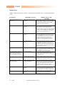
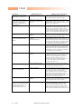
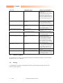
1
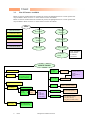
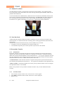
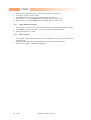
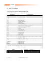
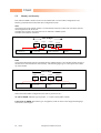
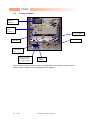
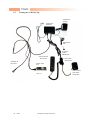
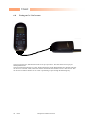
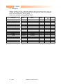
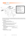
V3682
Level III Service Manual
Single Band 1900 MHz GSM
V3682
CONTENTS
Page Number
SECTION 1: GENERAL
1.1
1.2
1.3
Introduction
Motorola service policy for V3682 in warranty
General Safety Information
v
vi
vii
SECTION 2: V3682 DESCRIPTION
2.1
2.2
2.3
2.4
Specifications of V3682
V3682 Overview
Connector Pinout
Talk time, Weight and Volume Matrix
2
3
4
4
SECTION 3: FEATURE LIST
3.1
List of Features available
6
3.2
3.3
3.4
3.5
3.6
3.7
3.8
3.9
Menu
Phone Book
Call Related Features
Messages
Phone Set Up
Network selection
Call Meters
Accessory set-up
6
7
7
8
9
10
10
11
SECTION 4: DISASSEMBLY & PARTS
4.1
4.2
4.3
4.4
4.5
4.6
Dissasembly Introduction
Recommended Tools
Disassembly Procedure
Assembly procedure
Exploded Parts diagram
Replacement parts
13
13
13
13
16
17
SECTION 5: SIM CARDS AND SECURITY
5.1
5.2
5.3
5.4
5.5
Manual test mode
Live Sim Card
Personality Transfer
GSM Test Command
Identity and Security
19
19
19
21
22
SECTION 6: REPAIR & TEST PROCEDURES
6.1
6.2
6.3
6.4
ii
of 46
Repair introduction
Mechanical repairs
Basic modular troubleshooting
Software Upgrade
European Customer Services
24
24
24
27
V3682
6.5
6.6
6.7
6.8
Flexing
Testing on HP 8922
Testing PCB only on Car Kit Set Up
Testing on Go / NoGo Tester
27
28
29
30
SECTION 7: ACCESSORIES
7.1
Accessory Statement
32
SECTION 8: GLOSSARY OF TERMS
8.1
iii
of 46
List of Abbreviations
35
European Customer Services
V3682
SECTION 1: GENERAL
iv
of 46
European Customer Services
V3682
1.1
Introduction
This manual is intended for use by technicians familiar with similar types of equipment. It contains all
service information required for the equipment described and is current as of the printing date.
The scope of this document is to provide the reader with basic information relating to the V3682, and
also to provide procedures and processes for repairing the units up to and including Level 2 repair.
Level 1 and 2 repairs involve the following activities to be carried out: •
•
•
•
•
•
•
1.Unit swap out
2.Repairing of mechanical faults
3.Basic modular troubleshooting
4.Testing and verification of unit functionality
5.Upgrading software
6.Flexing units
7.Initiate warranty claims and send faulty modules to Level 3 or 4 repair centres.
Computer Software Copyrights
The Motorola products described in this instruction manual may include copyrighted Motorola
computer programs stored in semi-conductor memories or other media. Laws in the United States and
other countries preserve for Motorola certain exclusive rights for copyrighted computer programs,
including the exclusive right to copy or reproduce in any form the copyrighted computer program.
Accordingly, any copyrighted Motorola computer programs contained in the Motorola products
described in this instruction manual may not be copied or reproduced in any manner without the
express written permission of Motorola. Furthermore, the purchase of Motorola products shall not be
deemed to grant either directly or by implication, estoppel, or otherwise, any license under the
copyrights, patents or patent applications of Motorola, except for the normal non-exclusive, royalty
free license to use that arises by operation of law in the sale of a product.
v
of 46
European Customer Services
V3682
1.2
Motorola Service Policy for V3682 in warranty
1.2.1
Warranty:
Product will be sold with the standard 12 months warranty terms and conditions. Accidental damage,
misuse, and retailers extended warranties will not be supported under warranty. Non warranty repairs
will be available at agreed fixed repair prices. Refer to the latest version of CSB 235 for details.
Proof of purchase will be required to validate warranty claims.
1.2.2
Out of Box Failure Policy
Refer to the latest version of CSB 270 for the definition of Out of Box Failures, and for
specific instructions.
1.2.3
Product Support
Customers original units will be repaired but not refurbished as standard. Level I shops may replace
accessories and Level I parts; Level II shops may replace non-soldered parts; Level III shops may
perform some board level repairs. The U.S. National Service Center makes all repairs.
1.2.4
Customer Support:
Consumers should call 1 - 800 331 - 6456. Motorola Warranty Authorized Service Centers
should call 1 - 877 777 - 7520 55# for access to Technical Support.
1.2.5
Replacement Parts Ordering
Only shops authorized to carry out repairs will be able to purchase spare parts. Orders for spare parts
should be placed with the Accessories and Aftermarket Division (AAD) of Motorola. Refer to the
latest version of CSB 260 for details.
vi
of 46
European Customer Services
V3682
1.3
General Safety Information
1.3.1 Portable Operation
• DO NOT hold the radio so that the antenna is very close to, or touching, exposed parts of the body,
especially the face or eyes whilst transmitting. The radio will perform best if it is held in the same
manner as you would hold a ‘land’ telephone handset, with the antenna angled up and over your
shoulder.
•
DO NOT operate the portable phone in an aircraft. Switch off your telephone. The use of a cellular
telephone in an aircraft may be dangerous to the operation of the aircraft, disruption of the Cellular
Network may occur, and is illegal. Failure to observe this instruction may lead to a suspension or
denial of Cellular Telephone Service to the offender, or legal action, or both.
1.3.2 Mobile/Portable Operation - Telephone use in Vehicles:
• All equipment must be properly grounded according to installation instructions for safe operation.
•
Users are advised to turn off their equipment when at a refueling point.
•
Safety is every driver’s responsibility. Cellular telephones should only be used in situations in
which the driver considers it safe to do so.
1.3.3 General
• DO NOT allow children to play with any radio equipment containing a transmitter.
•
DO NOT operate this equipment near electrical blasting caps or in an explosive atmosphere.
Mobile Telephones are, under certain conditions, capable of interfering with blasting operations.
When you are in the vicinity of such work, look out for and observe signs cautioning against
mobile radio transmission. If transmission is prohibited, you must turn off your mobile telephone
to prevent any transmission.
In standby mode the mobile telephone will automatically transmit to acknowledge a call if it is not
turned off.
•
Refer to the appropriate section of the product user manual for additional pertinent safety
information
•
All equipment should be serviced only by a Motorola qualified technician.
vii
of 46
European Customer Services
V3682
SECTION 2:
V3682
DESCRIPTION
1
of 46
European Customer Services
V3682
2.1
Specifications of V3682
General
Function
Frequency Range GSM PCS
1850.2 - 1909.8 MHz Tx
1930.2 - 1989.8 MHz Rx
Channel Spacing
Channels
Modulation
Transmitter Phase Accuracy
Duplex Spacing
Frequency Stability
Operating Voltage
200 kHz
174 GSM/374 DCS carriers with 8 channels per carrier
GMSK at BT = 0.3
5 Degrees RMS, 20 Degrees peak
45 MHz GSM
95Mhz DCS
+ 0.10 ppm of the downlink frequency (Rx)
+3.0V dc to +5.1V dc (battery)
+4.4V dc to +6.5V dc (external connector)
Typically 225 ma avg, 1.1A peak
Typically 7.5 ma (DRX2)
82mm(L) X 43mm(W) X 26mm(H)
72 cc
83 g
-10C to +55C
Transmit Current
Stand-by Current
Dimensions
Size (Volume)
Weight
Temperature Range
Transmitter
Function
RF Power Output
Output Impedance
Spurious Emissions
Receiver
Function
RF Level
RX bit error rate (100 k bits)
Channel Hop Time
Time to Camp
Speech Coding
Function
Speech Coding Type
Bit Rate
Frame Duration
Block Length
Classes
Bit Rate with FEC Encoding
2
Specification
of 46
Specification
33 dBm + 2dB GSM/ 30 dBm + 2 dB DCS
50 ohms (nominal)
-36 dBm from 0.1 to 1 Ghz
-30 dBm from 1 to 4 Ghz
Specification
-102 dBm
< 2%
500 microseconds
Approximately 5-10 seconds
Specification
Regular Pulse Excitation / Linear Predictive Coding with Long
Term Prediction. (RPE LPC with LTP).
13.0 k bps
20 ms
260 bits
Class 1 bits = 182 bits. Class 2 bits = 78 bits
22.8 k bps
European Customer Services
V3682
2.2
V3682 Overview
The V3682 has been marketed as the lightest and smallest dual band mobile phone in the world. It is
now designed with the new Whitecap Chipset to allow the unit to operate at a lower working voltage
and therefore prolong battery life, in both Standby and Talk time.
The holographic display is now fitted into the flip to allow more room on the keypad.
This product is a replacement for Startac 130 and its main features include: • Smaller and more stylish form
• Single Band 1900 MHz GSM
• Longer Talk time / Standby time
• Large bit mapped 96 X 54 display with 1 line of Icons and Optimax holographic display
• Class II Sim tool kit
• Internal headset
• Potential to support Half Rate and Enhanced Full Rate modes of transmission (dependant on
Network)
• Asian SMS
• Asian Phonebook.
• Extended GSM
The units will be made of a Polycarbonate plastic with the display and speaker fitted within the flip.
The bottom part of the clam will contain the keypad the LOGIC / RF PCB, the Mic, earpiece flex
connection, external accessory connector and volume buttons. There will be two types of battery doors
available each to fit the standard and long life batteries, the phone accepts a 3V or 5V mini SIM card
which fits into the SIM slot underneath the battery. There will be no connection or fitting for an
Auxiliary battery.
The Antenna is usually a fixed stub type antenna.
The Service indicator will as for other Startac products display a Green light whilst in service, a Red
light whilst out of service and will flash Amber when roaming.
Fig 2.1 Mechanical
pictorial Overview
Headset Jack
Socket
Speaker
Holographic
Display
Flip
Vol. up
Service
Indicator
Mute button
Antenna
Keypad
Smart Key
Batt Door
Release
IMEI & MSN
Label
Battery
Contacts
Vol. Down
3
of 46
SIM Contacts
European Customer Services
Accessory
Connector
V3682
2.3 Connector Pinout
15
1
123456789101112131415-
2.4
RF Ground
RF In/Out
RF Ground
Battery Feedback
Manual Test Line
Not connected
Not Connected
Audio In
Audio Out / On-Off
Battery Ground
RTN
CMP
TRU
External B+
Analogue Ground
Talk Times, Weight and Volume Matrix
✸
White holographic film on display
Weight
Talk Time
Standby time
(grams)
(minutes)
(hours)
Volume
(cubic
cm)
TBD
69
69
80
53
72
77
92
100-130
130-160
260-330
70-125
95-160
190-320
TBD
TBD
TBD
TBD
4
of 46
Name
Transceiver Only
Transceiver with 400 mAh LI Slim Batt
Transceiver with 520 mAh LI Slim Batt
Transceiver with 1000mAh Extended
capacity battery
Transceiver with 200mAh high
performance battery
European Customer Services
V3682
SECTION 3: FEATURE LIST
5
of 46
European Customer Services
V3682
3.1
List of Features Available
Below are the list of Menu functions available at present, all highlighted text are or menu options that
may be added in future versions i.e. on the release of Voice Annotation.
Below are the list of Menu functions available at present, all highlighted text are or menu options that
may be added in future versions i.e. on the release of Voice Annotation.
Menu
1st Generation Menu
Phone Book
Network
Selection
Call Related
Features
Call Meters
Messages
Phone Setup
2nd Generation Menu
3rd Generation Menu
4th Generation Menu
Th Generation Menu
6th Generation Menu
Only Available
with Headset
or Car Kit
connected
Accessory
Setup
PHONE BOOK
Personal Numbers
1.Last Calls made
2.Last calls received
3.Erase all numbers
Last 10 Calls
Find Entry
by Name
Enter Name
Find Entry
By Location
Enter Location
Add Entry
1.Add to Phone memory
2.Add to SIM card memory
1.Call Number
2.Modify Name or
number
3.Erase name or
number
My phone number(s)
Fixed dialing
View fixed dial list
Setup
fixed
Dialing
1.On
2.Off
3.Edit Entry
4.Add Entry
5.Erase Entry
Check Capacity
Prevent access
1.To Phone memory
2.To SIM memory
3.To Fixed Dial list
One-Touch
Dial Setting
6
Enter
Pin2
of 46
European Customer Services
1.Check phone Capacity
2.Check SIM capacity
1.No memory restrictions
2.To SIM card memory
3.To phone memory
4.To phone and SIM memory
V3682
CALL RELATED
FEATURES
Show battery meter
Restrict my
Phone number
1.Show ID on next call
2.Restrict ID on next call
Call Diverting
Talk and Fax
1.On
2.Off
Call waiting
1.On
2.Off
Call Barring
Bar outgoing calls
1.Int’l Calls
2.Int’l Calls Except home
3.All Calls
4.Off
Bar Incoming Calls
1.When Roaming
2.All Calls
3.Off
Change Bar password
Cancel all barring
Divert Voice calls
Divert Fax Calls
Divert Data Calls
1.On
2.Off
1.On
2.Off
Divert when unavailable
1.On
2.Off
Divert all Voice calls
1.On
2.Off
Detailed Diverting
If Busy
1.On
2.Off
Cancel all diverting
If not reachable
If No Answer
7
of 46
European Customer Services
1.On
2.Off
1.On
2.Off
V3682
Messages
Call Voicemail
Received messages
Go to Next message
Delete Message
Return Call
Edit Message
1.Send Message
2.Store Message
Reply to message
Delete all messages
Outgoing Messages
Go to next message
Send message
Edit message
Delete message
8
of 46
Cell broadcast
1.On
2.Off
Message Settings
1.Voicemail Number
2.Service Centre
3.Expiry Period
4.Outgoing message type
European Customer Services
1.Send message
2.Store message
V3682
PHONE SETUP
Select Phone line
Adjust Ring volume
Ring or Vibrate
1.Ring only
2.Vibrate only
3.Vibrate then ring
4.No ring or vibrate
Set Ringer Tone
Standard Tone
.
.
Music Tone
Set Ringer Tone 2
Phone Lock
Automatic Lock
Adjust Contrast
Lock Now
Change SIM PIN mode
Require SIM card pin
1.On
2.Off
3.Change SIM pin Code
New security code
Extended menus
1.On
2.Off
Show time and Date
Set Time and Date
Set Time format
9
of 46
Language Selection
English
.
.
Automatic
Battery saving mode
1.On
2.Off
Select Keypad tones
1.Normal Tones
2.Single Tones
3.No Tones
Phone Status
1.Status review
2.Master reset
3.Master Clear
European Customer Services
1.On
2.Off
V3682
NETWORK
SELECTION
Available
Networks
1.Register Now
2.Make Preferred
Network Search
Registration
Preferences
1.Automatic Search
2.Manual Search
Frequency of
Search
1.Slow Search
2.Medium Search
3.Fast Search
4.Continuous Search
Add network
to List
1.Choose From Available
2.Choose From Known
3.Add new Network Code
Preferred
Networks
1.Move to New Location
2.Delete Selection
CALL METERS
Show Call charges
1.Show last call
2.Total for all calls
3.Credit remaining
Show call timers
1.Show last call
2.Total for all calls
3.Reset all timers
Set audible Call Timers
Single Alert Timer
1.On
2.Off
Repetitive Timer
1.On
2.Off
Set in call Display
1.Show time per call
2.Show Charge per call
3.Show total Call charges
4.No in call display
Call charge settings
Reset Call charges
Set Total Charge Limit
Set Charge Type
10
of 46
European Customer Services
1.On
2.Off
1.Units
2.Currency
V3682
ACCESSORY
SETUP
NB. THIS MENU IS ONLY AVAILABLE WITH EITHER HEADSET PLUGGED IN OR
WHEN INSTALLED IN A CAR KIT.
Mute Car Radio
1.On
2.Off
Automatic answer
1.On
2.Off
Automatic Handsfree
1.On
2.Off
Safety Timer
1.On
2.Off
Auxiliary Alert
1.On
2.Off
11
of 46
Dependant on
type of car kit
European Customer Services
V3682
SECTION 4: DISASSEMBLY &
PARTS
12
of 46
European Customer Services
V3682
4.1 Disassembly Introduction
The V3682 has no screws to hold it together and is held together by plastic catches, these are delicate
and should be parted using the upmost care. Also the display flex cable can be torn or broken without
too much stress being applied so again caution should be taken on dissassembly or assembly.
Ensure that a properly grounded high impedance conductive wrist strap is used whilst performing any
tasks during the disassembly and assembly of the unit
Avoid stressing the plastics in any way to avoid damage to either the plastics or internal components.
!! CAUTION !!
Many of the intergrated devices used in this equipment are vulnerable to damage from
electro-static charges. Ensure that adequate static protection is in place when handling,
shipping and servicing the internal components of this equipment.
4.2
Recommended Tools
The following tools are recommended for use during the assembly / disassembly of the V3682.
•
Anti-static Mat Kit - 0180386A82, includes:
Antistatic mat 66-80387A95
Ground Cord 66-80334B36
Wrist Band 42-80385A59
•
Plastic Bladed Tool SLN7223A
4.3
Disassembly Procedure
The following set of diagrams will demonstrate the correct sequence and action required to disassemble
the V3682
The use of the exploded diagram on page 18 may be of some assistance for part recognition.
4.4
Assembly Procedure
Once the unit is disassembled and the repair is carried out, the unit must then be reassembled, this is
carried out in the exact reverse order as the disassembly.
13
of 46
European Customer Services
V3682
1.Remove Battery door
by pressing up on latch
and pulling door.
4.Remove the LED
Indicator
14
of 46
2.Remove the battery
from pushing from the
bottom and lifting
outwards.
3.Push down on Antenna
and screw Antenna Anticlockwise.
5.Push tool between latch
and housing to prize open
European Customer Services
V3682
7.Carefully lift the retaining
clip on the flex connector.
Then pull the flex from the
connector.
6.Remove with care the
backhousing from the front.
Remove keypad
PCB from board
8.Lift PCB out of
front housing
15
of 46
European Customer Services
V3682
4.5
Exploded Parts Diagram
SWF3076DA
1
4
2
3
8
5
6
7
10
11
9
15
14
16
of 46
16
European Customer Services
12
13
V3682
4.6
Replacement Parts
Xcvr Item Number
Spare Xcvr Number
Rear Hsng
Hinge Mechanism
Frnt Hsng Assy
Flip Assy
Keypad PCB
Keypad
SW Array Domes
Escutcheon
Lens
Mic grommet
Mic 6mm
Light Guide
Antenna Insert
Stubby Antenna
Batt Door
17
of 46
1
2
3
4
5
6
7
8
9
10
11
12
13
14
15
16
SWF3076DA
SE0044AB1Z1
0104793Z01
5504765Z02
0104792Z01
0185763G01
SYN6939A
3809378T02
4004877Z02
5403796S01
6185833G02
0585699J01
5009135L07
6185635H02
4385988H01
0185829G02
SYN 7117B
European Customer Services
V3682
SECTION 5: SIM CARDS AND
SECURITY
18
of 46
European Customer Services
V3682
5.1 Manual Test Mode
The GSM Motorola V3682 is equipped with a manual test mode capability. This capability allows
service personnel to take control of the unit, and by entering certain keypad commands, make the unit
performs desired functions.
To enter the manual test command mode, a GSM / DCS test sim (Part No 8102430Z01) must be used.
The test sim is inserted into the SIM slot beneath the battery (See figure 6.1), the battery should then
be re-inserted and the unit powered on. The # button should then be pressed for approximatly 3
second until ‘test’ appears on the display, and the correct commands must then be followed.
Figure 6.1 SIM Card insertion
5.2 Live Sim Card
A SIM (Subscriber Identity module) card will be required to access the existing local GSM / DCS
cellular network, or remote networks when travelling. (If the roaming agreement has been made with
the provider.)
The SIM card contains all the data necessary to access GSM services, and also:
• The ability to store user information such as phone numbers etc…
• All information required by the network provider to provide use to the network
5.3 Personality Transfer
5.3.1
Introduction
Personality Transfers are required when a phone is Express Exchanged or when the main board is
replaced. The reason for personality transfers are to reproduce the customer’s original personalized
details such as menu and stored memory such as phone books etc… or even just to program a unit with
basic user information such as language selection. There are two possible methods of transferring this
information from unit to unit, or with a master transfer, card to unit: • Normal Transfer is used when the customer’s original unit still powers up and as discussed above
the customers personalized menu selections etc… are required to be transferred to the replacement unit.
• Master Transfer is used when the faulty unit will not power up and the transfer is used to configure
the replacement board to a set standard.
Below is the procedure to set up a Master Transfer Card and to carry out each method of transfer
correctly.
5.3.2
Normal Transfer
1.
2.
3.
Insert transfer card into ‘Donor’ Unit. Turn unit on till ‘Clone’ appears.
Enter 021# to upload first block of data. ‘Please wait’ will be displayed..
Remove card.
19
of 46
European Customer Services
V3682
4.
5.
6.
7.
8.
Insert card into replacement unit, or unit with new main RF / Logic PCB.
Turn unit on wait till ‘Clone’ appears.
Enter 03# ‘Please wait’ will be displayed while data is transferred.
Repeat steps 1 – 6 but enter 022# at step 2 to transfer data on to Clone card.
Repeat steps 1 – 6 but enter 025# at step 2 to transfer data on to Clone card.
5.3.3
Master SIM Card Creation
1.
2.
Insert transfer card into a unit with the desired setup Pwr on and wait till unit displays ‘Clone’
Enter 024# to copy unit ‘personality’ onto card. ‘Please wait’ will be displayed
3. Master Transfer card is created.
5.3.4
1.
Master Transfer
2.
3.
Insert Master Transfer Card (explained above) into replacement unit. Pwr on and wait till unit
displays ‘Clone’
Enter 03# to download data into replacement unit. Please wait will be displayed.
When ‘Clone’ reappears download is completed.
20
of 46
European Customer Services
V3682
5.3
GSM Test Commands
This is a list of Level 1 and 2 Test commands available to V3682
Table 6.1 Test commands
GSM Test Commands
Key Sequence
Test Function/Name
#(hold down for 2 seconds)
Enter manual test mode
01#
Exit manual test mode
07x#
Mute RX audio path
08#
Unmute RX audio path
09#
Mute TX audio path
10#
Unmute TX audio path
15x#
Generate tone
16#
Mute tone generator
19#
Display S/W version number of Call Processor
20#
Display S/W version number of Modem
36#
Initiate acoustic loopback
37#
Stop test
38#
Activate Mini SIM
39#
Deactivate Mini SIM
43x#
Change audio path
47x#
Set audio volume
51#
Enable sidetone
52#
Disable sidetone
54#
Show Service Indicator LED 0 - Off / 1 – Red / 2 – Green / 3 – Amber
(Flip must be Closed)
57#
Initialize non-volatile memory
58#
Display security code
58xxxxxx#
Modify security code
59#
Display lock code
59xxx#
Modify lock code
60#
Display IMEI
980# / 981#
DCS / GSM mode
99#
Display all display pixels
15XX#
90
91
Vib
Ringer
21
of 46
0 or Omitted
1
2
European Customer Services
36XX#
Full Rate
Enhanced Full rate
Half Rate
V3682
5.5
Identity and Security
Each Motorola GSM Cellular Cassette will be labelled with various number configurations. The
following information describes what these configurations mean.
MSN
The mechanical Serial Number (MSN) is an individual unit identity number and will remain with the
unit throughout the life of the unit.
The MSN can be used to log and track a unit on Motorola’s EPPRS system.
The MSN is divided into 4 sections.
MSN 10 Digits
3 digits
APC
Account Product Code
I.e. Startac 130
1 digit
DC
Distribution Center
I.e. Easter Inch
2 digits
DC
4 digits
SNR
Date Code: Year and
Month of Shipment
Units individual serial
number
Figure 5.2 MSN label breakdown
IMEI
The International Mobile station Equipment Identity (IMEI) number is an individual number unique to
the PCB and is stored within the unit’s memory. The following figure gives a description of the make
up of this number.
IMEI 16 Digits
Type Approval code
6 digits
2 digits
6 digits
2 digits
TAC
FAC
SNR
IU
Distribution Center
factory code
Individual PCB Serial
Number
Internal use – spare
digits
Figure 5.3 IMEI label breakdown
Some other label number configurations that will be present will be: XCVR NUMBER: Identifies type of product. i.e. V3682 (Usually SWF number)
PACKAGE NUMBER: Determines type of equipment, mode in which it was shipped and language
with which it was shipped.
22
of 46
European Customer Services
V3682
SECTION 6: REPAIR AND TEST
PROCEDURES
23
of 46
European Customer Services
V3682
6.1 Repair Introduction
The V3682 is divided into 4 main sections when it comes to part replacability: The flip which contains
the display module and speaker, the mechanical parts, the keypad PCB and the main RF / Logic PCB.
If the RF / Logic board is required to be changed then a full service tranceiver should be ordered as
there is no replacement PCB available. Also a personality transfer would be necessary.
6.2
Mechanical repairs
Assembly replacement level troubleshooting and repair of the V3682 is limited to isolation and
replacement of the main mechanical parts only (See Exploded parts diagram and associated parts list)
NB. For the immediate future, the front housing and flip assemblies will be ordered as 2 separate
parts but cannot be disassembled once together.
6.3
Basic Modular Troubleshooting
The troubleshooting information in Table 2 shows some typical malfunction symptoms, and for the
corresponding verification and repair procedures refer to the disassembly instructions located in the
disassembly section of this manual. (Section 5).
NOTE
24
of 46
Defective Logic/RF assemblies must be replaced
with pre-tested, pre-phased assemblies
European Customer Services
V3682
Repair Chart
Table 2. GSM V3682 Cellular Telephone: Troubleshooting and Repair Chart. (Assembly Replacement
Level).
SYMPTOM
Personal telephone will not turn
on or stay on
2. Personal telephone exhibits poor
reception and/or erratic operation
(such as calls frequently dropping,
Weak and/or distorted audio, etc.).
3. Display is erratic, or provides
Partial or no display.
PROBABLE CAUSE
a) Battery pack either discharged
or defective
Measure battery voltage across a 50 ohm (>1 Watt)
load. If the battery voltage is <3.25 V dc, recharge
the battery using the appropriate battery charger. If
the battery will not recharge, replace the battery.
If battery is not at fault, proceed to b.
b) Battery connectors open or
misaligned.
Visually inspect the battery connectors on both the
battery assembly and the portable telephone.
Re-align and, if necessary, replace either the
Battery or the battery connector assembly. Removing
the battery connector assembly has to be done with
extreme care to avoid damaging the PCB. If battery
connectors are not at fault, proceed to c
c) Logic/RF Board Assembly
Defective.
Remove the Logic/RF Assembly. Substitute a known
good assembly and temporarily reassemble the unit.
Depress the PWR button; if unit turns on and stays
on, disconnect the dc power source and reassemble
the telephone with the new Logic/RF Board
assembly. Verify that the fault has been cleared. If
the fault has not been cleared then proceed to d.
d) Keypad circuit board
Failure.
Replace the Keypad board. Temporarily connect a
+3.6 V dc supply to the battery connectors Depress
the PWR button; if unit turns on and stays on,
disconnect the dc power source and reassemble the
telephone with the new Keypad board. If the fault is
not cleared then proceed to e.
e) Display circuit failure
Disassemble unit and insert Main RF / Logic PCB
into new front Hsng with Flip. Inset Battery and
depress PWR button. Ensure unit stays on, if OK
reassemble unit in new housing assembly
Check to make sure that the antenna pin is properly
connected to the Logic/ RF assembly. If OK,
substitute a known good antenna. If the fault is still
Present, proceed to b.
a) Antenna is defective
b) Logic/RF Board Assembly
Defective.
Replace Logic/RF Assembly (refer to symptom 1c).
Verify that the fault has been cleared and
Re-assemble the unit with the new PCB.
a) Mating connections to / from
Display board faulty.
Remove rear housing from unit, check general
condition of flex connector if OK check that the Zif
connector is fully pressed down and that the flex
collars are flush with the plastic of the connector.If
not check Zif to PCB connections, if faulty
connector, replace RF / Logic PCB. If Ok proceed to
b.
Substitute the good RF / Logic PCB into a known
good front Hsng /Flip (with good Display circuit
board),if the fault is cleared rebuild with new Hsng /
Flip assy. If the fault is not cleared, re-install into the
original front Hsng / Flip Assy and proceed to c.
Replace Logic/RF Assembly (refer to symptom 1c).
Verify that the fault has been cleared and
Re-assemble the unit with the new PCB.
b) Display board is
Defective.
c) Logic/RF Board Assembly
Defective.
25
of 46
VERIFICATION AND
REMEDY
European Customer Services
V3682
SYMPTOM
4. Incoming call alert transducer
audio distorted or volume is too
low.
PROBABLE CAUSE
a) Faulty alert Transducer / Main
RF / Logic PCB defective
VERIFICATION AND REMEDY
Replace Logic/RF Board Assembly (refer to
symptom 1c). Verify that the fault has been cleared
and re-assemble the unit with the new PCB.
5. Personal telephone transmit
audio is weak, (usually indicated by
called parties complaining of
difficulty in hearing voice from
personal phone).
a) Microphone connections to
The main RF / Logic board are
defective.
Gain access to the Microphone as described in the
DISASSEMBLY instructions in this manual. . Check
connections. If connector is faulty proceed to c if the
connector is OK, proceed to b.
b) Microphone defective
Gain access to microphone .Disconnect
and substitute a known good Microphone. Place a
call and verify improvement in portable transmit
signal as heard by called party. If good, re-assemble
portable with new Microphone. If Microphone is not
at fault, re-install original Microphone and proceed
to c.
Replace Logic/RF Board Assembly (refer to
symptom 1c). Verify that the fault has been cleared
and re-assemble the unit with the new PCB.
Gain access to Logic/RF board as described in the
DISASSEMBLY instructions in this manual. Check
connection and the flexistrip from the earpiece to the
Logic/RF circuit board. If flex is at fault then replace
front / flip Assy. If Zif connector is at fault proceed
to d. If connection is not at fault, Proceed to b.
Remove RF / Logic PCB from housing and insert
into known good housing with flip, ensure good flex
connection. Place a call and verify improvement in
earpiece audio. If better, reassemble the phone with
the good Hsng. If it was no better then re-install into
the original housings and proceed to c.
c) Logic/RF Board Assembly
defective.
6. Personal telephone receive audio
is weak and/or distorted. (From
speaker)
a) Connections to/from
Logic/RF
Circuit board defective.
b) Earpiece Speaker defective.
7. Personal telephone will not
recognize/accept SIM card
c) Antenna assembly is
defective.
Attempt a re-phasing of the unit and recheck the
symptom. If symptom is the same but unit re-phases
correctly, check to make sure the two antenna
Connector is correctly soldered to the main board
and that the antenna is fitted correctly. If ok,
substitute a known good antenna assembly. If this
does not cure the fault, re-install the original
assembly then proceed to d.
d) Logic/RF Board Assembly
Defective.
d) Replace Logic/RF Assembly (refer to symptom
1c). Verify that the fault has been cleared and
Re-assemble the unit with the new PCB.
a) SIM card defective
Initially check that the contacts on the card are not
dirty. Clean if necessary, and check if fault has been
eliminated. If the contacts are clean, insert a
Known good SIM card into the portable telephone.
Power up the unit and confirm whether or not the
card has been accepted. If the fault no longer
Exists, the defective SIM card should be replaced. If
the SIM card is not at fault, proceed to b.
Replace Logic/RF Board Assembly (refer to
symptom 1c). Verify that the fault has been cleared
and re-assemble the unit with the new PCB.
b) Logic/RF Board Assembly
Defective.
8. Phone does not sense when flip is
Opened or closed (usually indicated
by inability to answer incoming
calls by opening the flip, or
inability to make outgoing calls).
26
of 46
a) Magnet in flip defective
Replace Front / flip assembly with known good one
refer to the DISASSEMBLY instructions in this
manual. Place call to portable phone and verify
ability to answer by opening flip. If faulty rebuild
phone with new front / flip Assy. If fault is still
present, replace original flip assembly and proceed to
b.
European Customer Services
V3682
SYMPTOM
9. Vibrator feature not functioning
PROBABLE CAUSE
b) Reed Switch defective
VERIFICATION AND REMEDY
Gain access to Keypad board as
described in the
DISASSEMBLY instructions in this
manual. Unsolder the reed switch and
replace with a known good one.
Reassemble unit. Place call to portable
phone and verify ability to answer by
opening flip. If fault still present, replace
original reed switch and proceed to c.
c) Keypad board is
Defective.
Replace the Keypad board with a known
good one. Place call to portable phone
and verify that the fault has been
eliminated. If not at fault, proceed to d.
d) Logic/RF Board Assembly
Defective.
Replace Logic/RF Board Assembly
(refer to symptom 1c). Verify that the
Fault has been cleared and re-assembles
the unit with the new PCB.
Replace vibrator. If fault still present,
replace original vibrator motor and
proceed to b.
Replace Logic/RF Board Assembly
(refer to symptom 1c). Verify that the
Fault has been cleared and re-assembles
the unit with the new PCB.
Test a selection of batteries in the rear
pocket of the desktop charger.
Check LED display for the charging
indications. If these are charging ok,
then the internal charger is at fault.
Replace Logic/RF Board Assembly
(refer to symptom 1c). Verify that the
Fault has been cleared and re-assembles
the unit with the new PCB.
Remove RF / Logic PCB from housing
and insert into known good housing with
flip, ensure good flex connection. Check
RTC time does not reset If Ok, rebuild
with good housing. If fault is still
present then replace front / flip Assy.
Fully ensure the ‘click’ is felt on the
jack socket.
Replace Logic/RF Board Assembly
(refer to symptom 1c). Verify that the
fault has been cleared and re-assemble
the unit with the new PCB.
a) Vibrator defective
b) Logic/RF Board Assembly
Defective.
10. Internal Charger not working
a) Faulty charger circuit on main
Board.
11. Real Time Clock resetting when
standard battery is removed.
Lithium button cell in the Flip may
be depleted.
12. No / Weak audio when using headset
a) Headset not fully pushed home
b) Faulty Jack Socket / Defective PCB
6.4
Software Upgrade
For information on setting up and equipment required for the flashing of software, contact Technical
Support at 1-877 777 - 7520 55#.
6.5
Flexing
For information on setting up and equipment for flexing, contact should be made with the local
technical support engineer.
27
of 46
European Customer Services
V3682
6.6
Testing on HP8922
HP8922
GSM Test
83220E
Down
Converter
Power Supply
Signal Cable
RF Cable
V3682 under
Test
Audio test cable,
and adapter. (See
prototype picture)
Battery
Emulator
NB At the time of release a final version for the Audio cable was unavailable; a photo and part
number will be available as soon as the final release is available.
28
of 46
European Customer Services
V3682
6.7
Testing on Car Kit Set Up
SSN4020A Speaker
SYN7066C –
DSP Box
SMN4103A Mic
Extension
Cable –
SKN4419A
Startac handset
– SCN2636A
SKN4491A –
RF Cable
Junction Box
– SLN6749A
V3682 under
Test
2700 external
card reader –
SLN6749A
29
of 46
European Customer Services
V3682
6.8
Testing on Go / NoGo tester
The set up for the GO / NOGO tester must be set up as per above. The tester must be set up as per
GSM specifications.
The test incorporates the basic live call, during which many of the RF parameters are checked. This test
can be ran in ‘Autotest’ mode, where the radio is classified at the end of the test as a Pass or Fail. This
can be used to indicate whether or not a unit is performing to spec through the Butt Plug only.
30
of 46
European Customer Services
V3682
SECTION 7: ACCESSORIES
31
of 46
European Customer Services
V3682
7.1 Introduction
A lthough the B attery packages are completely different to those used in the other Startac ranges, the
accessory socket remains standard so a great deal of the Startac type accessories are still compatible.
There is no requirement for any A uxiliary battery.
Accessories available and compatibility matrix
Accessory
Battery LiIon 500
Battery LiIo 1000
Battery NiMH 500
Battery LiPoly 800
Mini Travel Charger Euro
Mini Travel Charger UK
Std Desktop Charger
Mini Desktop Charger
HF Desktop Charger
Ultra Saver CLA
Headset
Cradle
Easy Install Car Kit
Pro Install Car Kit
Plastic Holster
Leather Pouch
Leather Case
32
of 46
B lister
BLS9050
BLX9100
BNX9050
BPS9060
CHA9050
CHA9060
CHA9150
CHA9250
CHA9350
CLA9000
HSK9000
HUC9050
HFK9050
HFK9450
CCA9150
CCA9050
CCA9060
Generic
SNN5435
SNN5451
SNN5341
TBD
SPN4604/ SYN7456
SPN4604/ SYN7455
SPN4573
SPN4640
TBD
SYN4241
SYN6962
SYN7698
S8464A
(SYN7695 cradle)
SYN7678
TBD
TBD
European Customer Services
V3682
*
*
*
*
*
*
*
*
*
*
*
*
*
*
*
*
*
StarT AC
130
Cd930
*
*
*
*
*
*
*
*
*
*
V3682
Voice Recognition Car Kit
Part Numbers for V3682 Voice
recognition Car Kit
1.SKN4937A – Fuse Cabling and mount
2.SYN7066C – DSP Box
3.SSN4020A - Speaker
4.SMN4103A - Mic
5.SYN7695A – Mounting Bracket
6.TRN5502A - Bracket
7.SKN4491A – RF Cable
8.SKN4834A – Power Cable
2
4
8
6
3
7
1
SJN8205A – Install and User manual
SJN8635A – Manual Insert
5
The V3682 Voice Recognition Car kit is a professional install handsfree car kit with improved full duplex performances
for the StarTAC models. The Kit uses the latest Digital Signal Processor (DSP) technology for high quality audio as well as
Voice Recognition (VR) algorythms, and includes all basic handsfree components, hang up cup, DSP HF box, speaker,
directional microphone, and cables.
Key VR Features:
- Activation word to make and answer calls
- Up to 100 names and phone numbers memory
- Selectable language prompts, up to 7 different languages
Key DSP Features:
- Superb full digital audio quality and clarity even at high driving speeds
- Improved full duplex audio allowing genuine two-way conversation
- Digital noise cancellation filtering out background noise
- Digital echo cancellation eliminating local and network echoes
Standard Features:
- Full hands-free capability for comfort and safety communication while driving
- Direct RF connection to external antenna for better coverage
- Directional microphone
- Intelligent rapid charge
- Programmable safety timer
- Entertainment mute
- Programmable automatic answer
- Auxiliary alert
Packaging Information:
- New retail box, descriptions in 9 languages
- Installation & User manuals, 16 languages
33
of 46
European Customer Services
V3682
SECTION 8: GLOSSARY OF
TERMS
34
of 46
European Customer Services
V3682
8.1 List of Abbreviations
Those marked ** are Motorola specific abbreviations.
A Interface
A3
A5
A8
AB
A-bis
ACCH
ACSE
AGCH
AMPS
AOC
ARFCN
ARQ
ASIC
AUC
AUT (H)
Interface between MSC and BSS
Authentication algorithm
Stream cipher algorithm
ciphering key generating algorithm
Access Burst
Interface between BSC and BTS
Associated Control Channel
Association Control Service Element
Access Grant Channel
Advance Mobile Phone System
Advice of charge
Absolute Radio Frequency Channel Number
Automatic Request for retransmission
Application Specific Integrated Circuit
Authentication Center
Authentication
BA
BAIC
BAOC
BCC
BCCH
BCD
BCU
Bm
BN
BS
BSC
BSIC
BSS
BSSAP
BSSC
BSSMAP
BSSOMAP
BSU
BTS
BCCH Allocation
Barring of All Incoming Calls
barring of all Outgoing Calls
Base Transceiver Station (BTS) Color Code
Broadcast Control Channel
Binary Coded Decimal
BTS Control Unit **
Full-rate traffic channel
Bit Number
Base Station
Base Station Controller
Base Transceiver Station Identity Code
Base Station System
BSS Application Part (DTAP and BSSMAP)
Base Station System Control Cabinet **
Base Station Systems Management Application Part
BSS Operation and Maintenance Application Part
Base Site Controller Unit **
Base Transceiver Station
CA
CBCH
cc
cc
CC
CCBS
CCH
CCCH
CDMA
CFS
CFU
CLIP
CLIR
CM
COLP
COLR
CONF
35
of 46
Call Allocation
Call Broadcast Channel
Call Control
Country Code
Cellular Cassette
Completion of Calls to Busy Subscribers
Control Channel
Common Control Channel
Code Division Multiple Access
Call Forwarding on mobile Subscriber busy
Call Forwarding Unconditional
Calling Line Identification Presentation
Calling Line Identification Restriction
Connection Management
Connected Line identification Presentation
Connected Line identification Restriction
Conference Call add on
European Customer Services
V3682
CSPDN
CUG
CW
Circuit Switched Public Data Network
Closed User Group
Call Waiting
DB
DBS
DCCH
DET
DFE
DISC
DL
Dm
Dm
Dp
DRCU
DRX
DTAP
DTE
DTMF
DTX
Dummy Burst
Distributed Base Station **
Dedicated Control Channel
Detach
Decision Feedback Equalizer
Disconnect
Data Link (layer)
Control Channel (ISDN terminology applied to mobile service)
Signaling channel
Dialed Pulse
Diversity Radio Channel Unit**
Discontinuous Reception
Direct Transfer Application Part
Data Terminal Equipment
Dual Tone Multi-Frequency (tone signaling type)
Discontinuous Transmission
E
Eb/No
EC
Ec/No
EGSM
EFR
EIR
EIRP
EMC
EMX
ETSI
erlang
Energy per Bit/Noise floor
Echo Canceller
Ratio of energy per modulating bit to the noise spectral density
Extended Group special Mobile
Enhanced Full Rate
Equipment Identity Register
Effective Isotropic Radiated Power
Electromagnetic Compatibility
Electronic Mobile Exchange **
European Telecommunications Standards Institute
FACCH
FACCH/F
FACCH/H
FB
FCCH
FEC
FN
FR
FTAM
GCC
GMSC
GMSK
GSM
GSM MS
GSM PLMN
HANDO
HDLC
HLR
HOLD
HPLMN
HPU
HR
HSN
36
of 46
Fast Associated Control channel
Full rate Fast Associated Control channel
Half rate fast Associated Control channel
Frequency correction burst
Frequency Correction Channel
Forward Error Correction
Frame Number
Full Rate
File Transfer Access Management
Global Call Center
Gateway Mobile Services Switching Center
Gaussian Minimum Shift Keying
Group Special Mobile
GSM Mobile Station
GSM Public Land Mobile Network
Handover
High Level Data Link Control
Home Location Register
Call Hold (Supplementary Service)
Home PLMN
Hand Portable Unit
Half Rate
Hopping Sequence Number
European Customer Services
V3682
I
IA5
ID
Information (frames)
International Alphanumeric 5
Identification
IMEI
IMM
IMSI
IN
INDY
ISC
ISU
ISDN
ISUP
IWF
International Mobile Equipment Identity
Immediate assignment message
International Mobile Subscriber Identity
Intelligent Network
Iridium 9500 handset
International Switching Center
Iridium Subscriber Unit
Integrated Services Digital Network
ISDN User Part
Interworking Function
Kc
Ki
ciphering Key
Individual subscriber authentication key
LAC
LAI
LAPB
LAPDm
Lm
LPC
LR
Location Area Code
Location Area Identification (Identity)
Link Access Procedure ‘B’ (balanced) channel
Link Access Procedure ‘DM’ (mobile ‘D’) channel
Traffic channel (with capacity lower than Bm)
Linear Predictive Code
Location Register
MA
MAH
MAI
MAIO
MAP
MCC
MCI
MD
ME
MF
MLSE
MM
MMI
MNC
MO
MO/PP
MoU
MRN
MS
MSC
MSCM
MSIN
MSISDN
MSRN
MT
MTP
MT/PP
Mobile Allocation
Mobile Access Hunting
Mobile Allocation Index
Mobile Allocation Index Offset
Mobile Application Part
Mobile Country Code
Malicious Call Identification
Mediation Device
Mobile Equipment
Multi-Frequency (tone signaling type)
Maximum Likelihood Sequence Estimator
Mobility Management
Man Machine Interface
Mobile Network Code
Mobile Originated
Mobile Originated Point to Point messages
Memorandum of Understanding
Mobile Roaming Number
Mobile Station
Mobile Services Switching Center
Mobile Station Class Mark
Mobile Station Identification Number
Mobile Station international ISDN number
Mobile Station Roaming Number
Mobile Termination
Message Transfer Part
Mobile Terminated Point to Point messages
NAMPS
NB
NE
North American-Advance Mobile Phone System
Normal Burst
Network Elements
37
of 46
European Customer Services
NET
NM
NHC
V3682
Norme European de Telecommunications
Network Management
Network Management Center
O&M
OACSU
OCB
OMAP
OMC
OMCR
OMCS
OSI
Operations and Maintenance
Off Air Call Set-Up
Outgoing Calls Barred
Operations and Maintenance Application Part (previously was OAMP)
Operations and Maintenance Center
Operations and Maintenance Center -Radio Part
Operations and Maintenance Center -Switch Part
Open System Interconnection
PAD
PCH
PDN
PIN
PLMN
POTS
PSPDN
PSTN
PTO
Packet Assembly Disassembly facility
Paging Channel
Public Data Networks
Personal Identification Number
Public Land Mobile Network
Plain Old Telephone Service (basic telephone services)
Public Switched Packet Data Network
Public Switched Telephone
Public Telecommunications Operator
QOS
Quality of Service
RAB
RACH
RBDS
RBU
RCU
REC
REL
RELP-LTP
REQ
RFCH
RFN
RLP
ROSE
RXCDR
RXLEV
RXQUAL
SABM
SACCH
SAPI
SB
SC
SCCP
SCH
SCP
SDCCH
SDL
SFH
SIM
SMS
SMSCB
SND
SP
38
of 46
Random Access Burst
Random Access Channel
Remote BSS Diagnostic Subsystem **
Remote Base Station Unit (PCN) **
Radio Channel Unit **
Recommendation
Release
Regular Pulse Excitation - Long Term Prediction
Request
Radio Frequency Channel
Reduced TDMA Frame Number
Radio Link Protocol
Remote Operations Service Element (a CCITT specification for O&M)
Remote Transcoder Unit **
Received signal level
Received signal quality
Set Asynchronous Balance Model
Slow Associated Control Channel
Service Access Point Indicator (Identifier)
Synchronization Burst
Service Center
Signaling Connection Control Part
Synchronization Channel
Service Control Point - an intelligent network entity
Stand-alone Dedicated Control Channel
Specification Description Language
Slow Frequency Hopping
Subscriber Identity Module
Short Message Service
Short Message Service Call Broadcast
SeND
Signaling Point
European Customer Services
SRES
SS
SS
STP
V3682
Signed RESponse (authentication)
Supplementary Service
System Simulator
Signaling Transfer Point
SYSGEN
SYStem GENeration
TA
TA
TCAP
TCH
TCH/F
TCH/FS
TCH/HS
TCP
TDMA
TE
TMN
TMSI
TN
TRX
TTY
TS
TUP
Terminal Adapter
Timing Advance
Transaction Capabilities Application Part
Traffic Channel
A full rate TCH
A full rate speech TCH
A half rate speech TCH
Transmission Control Protocol
Time Division Multiple Access
Terminal Equipment
Telecommunications Management Network
Temporary Mobile Subscriber Identity
Timeslot Number
Transceivers
TeleTYpe (refers to any terminal)
Time Slot
Telephone Users Part
UI
Um
Unnumbered Information frame
Air Interface
VAD
VLR
VLSI
VPLMN
Voice Activity Detection
Visited Location Register
Very Large Scale Integration (IC)
Visited PLMN
XC
XCDR
Transcoder
Transcoder **
3PTY
Three party service
39
of 46
European Customer Services
V3682 - RF SCHEMATICS
V3682 - AL SCHEMATICS
V3682 - BOARD OVERLAY - TOP SIDE
V3682 - BOARD OVERLAY - BOTTOM SIDE