1
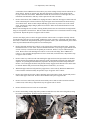
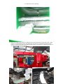
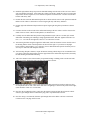
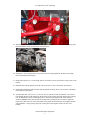
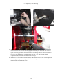
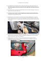
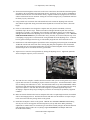
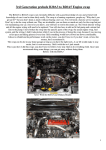
Installation Instructions Full Throttle 9.5” & 12” & 15” Suspension 99-05 GM 8-LUG- 6 LUG #9.5-99-6L Kit Hardware Torque Specifications Remember that actual torque may vary if lubricant is used, or extension bars are used with the torque wrench. Torque all re-used O.E. factory hardware to original vehicle torque specifications according to factory service manual. If in doubt concerning the torque specification of ANY fastener, always consult the factory service manual. Always consult factory service manual for sequence and torque specification of any O.E. parts being reassembled, such as ball joint nuts, and steering tie rod ends. For hardware supplied with this kit, use the following list as a guide for fastener torque: Bolt Size Torque 5/16 12-15 Ft-lbs 3/8 30 Ft-lbs 7/16 55 Ft-Lbs ½ 70 Ft-lbs 9/16 100 Ft-lbs 5/8 110 Ft-lbs Important Maintenance Information It is the end user’s responsibility to have all fasteners checked for proper torque after the first 200 miles, then every 3000 miles. Have a qualified professional mechanic or alignment specialist inspect the steering, suspension and driveline components immediately after installation, and at regular intervals thereafter. Please see Limited Lifetime Warranty sheet included with the kit, and mail in the warranty information card. Limited lifetime warranty will only be honored if the original purchaser mails in the warranty card. Disclaimer Notice: Installing this suspension system on any vehicle implies that you are in agreement with the following terms and conditions with respect to that vehicle, the vehicle owner, and any or all occupants of said vehicle at any time: Full Throttle Suspension is not responsible, and cannot be held responsible for any conditions of said vehicle including, but not limited to the following: 1) Any and all adverse behavior, premature failure, or breakage caused by oversized tires and wheels, improper installation, failure to follow instructions, or any general negligence caused by installer or owner of said vehicle. 2) Any breakage or premature failure caused by racing or driver negligence. 3) ANY incident determined to be caused by an increase height in said vehicle’s center of gravity. 4) ANY incident determined to be caused by improper installation. 5) ANY incident determined to be caused by a failure of materials. Full Throttle Suspension is to be held harmless by the installer of this lift kit, owner of said vehicle, ANY occupants of said vehicle, and any parties related directly or indirectly to said vehicle or owner of said vehicle. Full Throttle Suspension is to be held harmless by all parties mentioned during the course of any and all circumstances or incidence resulting from the installation of this lift kit. Full Throttle Suspension offers this kit strictly as a visual improvement of said vehicle over the factory aesthetics. The fact that the suspension system works and functions well is incidental, and it is not the intention of Full Throttle Suspension that said vehicle be modified for use on public highways sanctioned by the Department of Transportation, or any state or local governing body. Vehicle owner accepts sole responsibility for ensuring that said vehicle is not in violation of local, state, or federal laws or vehicle code. Please check local vehicle laws and regulations before modifying your vehicle. 9.5” Suspension | 99-01 GM 6 lug On 9.5” and smaller rear drive lines will not have to be extended, we recommend 12” and above for the rear drive line to be extended. The drive line angle being a few degrees off stock will not affect parts normal ware and tear. By Installing This Kit or having this kit installed on your vehicle, you are implying that you agree to the above terms and conditions. Please do not install this system if you do not agree. Important! Please read all instructions before attempting any work on the vehicle. We strongly recommend installation be done by a professional mechanic, in a shop with a suitable vehicle hoist. If attempting this installation as a do-it-yourselfer, please review this packet carefully BEFORE attempting any work on the vehicle. This packet uses standard nomenclature when referring to each side of the vehicle: LEFT side means DRIVER’S side, while RIGHT side means PASSENGER side. Required Tools and Equipment Please review this list before attempting any work; it is common to spend more time finding the correct tools and equipment during the installation than actually installing the kit---save time by making sure all of these things are readily available BEFORE beginning work on the vehicle. Good quality safety glasses and ear protection Professional Quality Floor Jack (or vehicle hoist) Tall Jack Stands (4) ½ drive Socket set and ratchets with metric, standard and deep sockets 3/8 drive Socket set and ratchets with metric, standard and deep sockets Hex Sockets (recommended) OR Allen wrench (hex key) set Compressor w/ impact wrench and air ratchet (recommended) Air hammer with flat pointed chisel, and shovel tip chisel bits Pickle fork type tie-rod separator, and ball joint separator GM torsion bar unloading tool (recommended) OR 2 jaw gear puller Transmission Jack (recommended) Plasma Torch (recommended) OR Sawzal with metal cutting blades MIG or equivalent wire feed welder with 75-25 Argon or better 4” grinder (recommended), or chisels and files ½” drill motor and drill index, (½” and ¾” drill bits required) Dead blow hammer (recommended), OR suitable ball pein hammer Soft face hammer Screwdrivers Pliers and Channel Locks Sidecutter type cutting pliers Pointed Heel bars (recommended), OR prybars Cotter pin assortment Tie wire and/or plastic zip ties Disassembly (front) 1. With vehicle on the ground, open hood and disconnect battery. Remove nut/washer assembly and rubber bushing from upper front shocks from under the hood. Raise front of vehicle and secure with jackstands under the frame. When placing the jackstands, keep in mind that you will be removing the entire front suspension, torsion bars, and torsion bar crossmember. NEVER ATTEMPT ANY WORK ON VEHICLE SUPPORTED WITH ONLY A JACK---ALWAYS USE JACKSTANDS! Remove both plastic and aluminum front skid plates. 2. Using GM torsion bar unloading tool release tension on the torsion bar adjusting keyway or “pork chop” within the torsion bar crossmember. Remove torsion bar adjusting bolt and threaded pad from ©2001 Full Throttle Suspension 2 9.5” Suspension | 99-01 GM 6 lug crossmember, then CAREFULLY release the keyway so that it hangs loosely from the torsion bar (as shown below). Repeat on opposite side, then slide torsion bars forward to release them from the keyways and lower control arms. IMPORTANT: Mark the torsion bars for left and right sides, and mark them front and back so that they will be replaced in the same orientation. 3. Remove front wheels, then CAREFULLY unplug and remove ABS wire from upper control arms and frame connection point. Remove brake line clip from upper control arm and also the brake line clip from vehicle frame. Remove brake calipers and hang up out of the way with tie wire to the vehicle frame. DO NOT let calipers hang by brake hoses. Remove brake rotors and label them for left and right side of vehicle. Remove nut attaching outer tie rod end to steering knuckle; detach outer tie rod end from steering knuckle using tie rod separator as shown below. DO NOT strike threaded area of tie rod end stud. Remove bearing cap from hub. Repeat this process on opposite side of vehicle. (NOTE: some shops prefer to remove the upper and lower control arms as a complete assembly with the steering knuckle, hub, and CV axle attached. Without the proper experience, equipment, and vehicle hoist, this can be a cumbersome and potentially dangerous operation; if this is your first installation, please follow from step 4 and disassemble the suspension to its individual parts. 4. Remove large hub nut from outer end of CV axle (shown above right) with 36mm socket. Strike the threaded end of the CV axle with a soft-faced dead blow hammer, (or by using a regular hammer with a block of wood), to loosen it from the splined part of the hub. Remove sway bar end link and put aside. Remove the 6 bolts attaching inner end of CV axle to the axle flange, then CAREFULLY remove CV axle assembly through bottom of lower control arm (as shown below). Repeat these steps on opposite side of vehicle. 5. Remove cotter keys and loosen the nuts attaching the upper and lower ball joint studs to the knuckle. Separate the ball joint studs from upper and lower points of the knuckle using ball joint (pickle fork) separator, or by striking the knuckle directly adjacent to the ball joint stud with a ball pein hammer. NOTE: Leave both upper and lower ball joint nuts loosely engaged on the threads of the stud in order to catch the knuckle and prevent it from falling when it breaks loose, (see arrows). 6. When both upper and lower ball joints have popped loose, remove nuts by hand and CAREFULLY remove knuckle with hub assembly. Repeat these steps on opposite side of vehicle. 7. Remove nuts, bolts and eccentric washers attaching upper control arm to frame, and carefully remove and set aside upper control arm. Remove shock absorber and repeat on opposite side. 8. Remove two lower control arm pivot bolts and carefully remove and set aside torsion bar and lower control arm (it will be heavy). Repeat these steps on opposite side of vehicle. 9. Remove bolted in section of lower rear crossmember. 10. Remove nuts holding steering drag link to pitman arm and idler arm, then remove drag link (steering bar) with tie-rod separator. Remove sway bar and set aside. ©2001 Full Throttle Suspension 3 9.5” Suspension | 99-01 GM 6 lug 11. Remove transfer case skid plate and front driveshaft and set aside. 12. Unplug and unclip the 4x4 switch and actuator wires from the right side axle tube and hang them out of the way. Unplug the rubber vent hose from the left side of the differential third member assembly. Remove the two nuts and bolts holding the right side of the differential assembly to the aluminum right side mounting bracket. 13. While supporting the differential with a transmission jack or floor jack, remove nuts and bolts from the two left side mounting ears attaching front third member assembly to vehicle frame. Carefully lower the differential assembly away from the vehicle and place it out of the way. NOTE: Perform all cutting and welding (next steps) before attempting reassembly. 14. Using Sawzall or plasma torch, cut and remove fixed section of crossmember from left side lower control arm rear pivot mount. Cut flush with backside of pocket and angle the rearward side of the cut slightly towards the outside of vehicle. You are removing the section that once provided the mounting location for the LEFT LOWER mounting ear of the differential housing; the cut piece should look like the picture (below right). ATT: ON 1500HD 2500HD AND 3500HD YOU MUST CUT FOR CLEARANCE FOR YOUR THIRD IDLER AS SHOWN IN THE PIC BELOW: ©2001 Full Throttle Suspension 4 9.5” Suspension | 99-01 GM 6 lug 15. Dress all cut edges with a grinder or sanding wheel. Paint or undercoat raw edges at this time. Hang rear lower crossmember into place using the factory bolts with 5/8” flat washers supplied from the backside. Position front upper control arm mount into place as shown below. Notice bigger hole is to the front and smaller hole is to the rear. ©2001 Full Throttle Suspension 5 9.5” Suspension | 99-01 GM 6 lug 16. Install the polyurethane droop stops into the threaded bushings on both sides of the rear lower control arm crossmember lift bracket. After letting the coating cool and dry, install the rear lower control arm drop bracket into the original rear, lower control arm pockets as shown below. Position crossmember bracket with factory bolts. 17. Position the left side front differential drop bracket as shown with the concave side pointed towards the FRONT of the vehicle as shown above. Fasten finger tight only with factory hardware. 18. Position right side differential drop bracket into place finger tight using factory hardware as shown below. 19. Clearance the fins on the left side of the differential housing at the area where it will be closest to the inside of the rear lower control arm drop bracket, as shown below. 20. Carefully raise the differential into position using transmission jack, (this is a two man job). Attach differential at mounting ears and flanges using supplied hardware, DO NOT tighten at this time. Use two ½” x 1-1/2” bolts for the right side, and 9/16 x 4” bolt for the left side. 21. After starting the bolts enough to support the differential, check the clearance between the left side of the housing and the inside of the drop bracket as shown below right. If you cannot see daylight between them or approximately 3/16” clearance, remove differential and repeat the clearance process as in step 53 until it fits with adequate clearance. 22. After ensuring adequate clearance, torque all fasteners starting with the larger rear crossmember bolts (rear lower control arm drop bracket), then the upper bolts for the differential drop brackets, and lastly the bolts holding the differential housing. 23. Take a few minutes to check the assembly for potential binding or rubbing, make sure the unit looks centered correctly and the horizontal sections look parallel as shown. 24. Check each side axle flange relative to the adjacent bolt hole in the lift kit bracket to make sure they are comparable side for side. This can be done with a straightedge as shown in the picture below right, (sides should be within 3/8” of each other). 25. Once the unit is tightened in place, gently draw the actuator wiring and plug down from the vehicle chassis to gain enough slack to reconnect the plug, and re-clip the harness as shown. 26. Once the wiring is reconnected, GENTLY pull enough slack in the rubber vent hose to reach and reconnect to the vent plug on the left side. ©2001 Full Throttle Suspension 6 9.5” Suspension | 99-01 GM 6 lug 27. Next use transmission jack or two people to raise the front lower control arm drop bracket into position into front lower control arm pockets. Hang with factory bolts as shown above. 28. Mount front upper control arm drop bracket into place as shown below with hardware supplied. 29. Position the sway bar with sway bar mounts up between the legs of the front lower control arm drop bracket. Maintain the FACTORY ORIENTATION of the sway bar with the link ends offset in the UPWARD direction. Through-bolt the sway bar mounts to the lower bracket tabs using 3/8 x 1-1/2” bolts and nuts as shown below. ©2001 Full Throttle Suspension 7 9.5” Suspension | 99-01 GM 6 lug 30. Use a spreader tool or nut and bolt to SLIGHTLY open up the downward legs of the front lower control arm drop bracket. Install the front crossmember strut with eight 7/16 x 1-1/4” bolts and nuts as shown below. 31. Install all eight nuts and bolts hand tight with the bolt heads towards the outside before tightening. 32. Use oil behind the washers at the visible places to prevent the powder coating from splintering while torquing the fasteners. 33. Position lower control arms into drop brackets using two 5/8 x 4-12” and two 5/8 x 5-1/2” bolts and nuts, DO NOT TIGHTEN at this time. Reinstall sway bar end links connecting lower control arms to sway bar on both sides of vehicle, and tighten the link hardware to factory spec. CAUTION: do not over-tighten sway bar links; the bushings do not need to “squeeze out” the sides, this is a common misconception. 34. Install upper control arms using cam bolts and the supplied oversized eccentric “D” washers. DO NOT TIGHTEN at this time. Optional tubular control arms shown in picture. ©2001 Full Throttle Suspension 8 9.5” Suspension | 99-01 GM 6 lug 35. With both upper and lower control arms mounted, reinstall spindles on both sides. Reinstall ball joint nuts and torque to factory specifications as shown below. 36. Reinstall CV axles from below the lower control arms, first fitting them into the hubs, then mating them with the differential flanges. 37. Install and torque the six CV axle flange bolts on each side to factory specification using Loctite on the threads. 38. Reinstall and torque the spindle nut to the outer end of the CV axle to the factory specification. 39. Install supplied drop drag link onto idler arm and pitman arm using factory nuts as shown. TIGHTEN nuts to factory specification. 40. Assemble idler link: (use one 5/8 x 2-1/2” bolt, two 5/8 nuts and six AN flat washers). One rod end bolts through the hole in the platform on the back side of the steering drag link, and the other end slips over the threaded pin on the welded angle brace as shown (below right). NOTE: Start with three washers UNDER the heim-joint at each end of idler link to provide plenty of clearance. Adjust the length of the idler link to fit on the same radius as the pitman arm and idler arm, then tighten jam nuts after installation. Swing steering drag link, (steering bar) left and right to make sure there is no binding. ©2001 Full Throttle Suspension 9 9.5” Suspension | 99-01 GM 6 lug 41. Install polyurethane bushings and steel sleeves in both ends of each tubular compression strut, then install one end of each strut to the left and right pairs of mounting ears on the back side of the rear lower control arm drop bracket, (the large rear lift kit crossmember). NOTE: it may be necessary to spread the ears slightly with a soft-faced hammer in order to engage the strut bushings and start the bolts, (they will straighten back out when torqued). Use four ½ x 4” bolts and nuts to attach compression struts, (two in this step and two in the next step). 42. Install two of the offset u-brackets (shown below) with hardware on the rear end of each compression strut. Swing the compression struts upward one at a time and put a mark where each tab will contact the transmission crossmember as shown. ©2001 Full Throttle Suspension 10 9.5” Suspension | 99-01 GM 6 lug 43. Carefully clean paint and undercoating at marked areas of crossmember with a wire wheel or sanding disk. After cleaning contact area to bare metal, clamp strut and ears back into position and tack weld the ears to the transmission crossmember as shown. Remove bolts and swing compression struts downward and out of the way to fully weld the ears as shown. Dress and paint bare metal areas with suitable paint or undercoating. After the tabs are cool and dry, swing compression struts back into position and install the two rear bolts, and torque all four bolts. 44. If installing dual front shock kit, install lower shock mount brackets around factory upper control arm. NOTE: The UPPER HALF of the LOWER shock mount bracket can be positioned by bolting into place using the factory brake line retaining bolts that thread into the upper control arm. Once the upper half is positioned by the OE bolts, through-bolt the lower half to the upper half using ½” x 2-1/2” bolts and nuts. 45. (Dual Shocks ONLY). Next install the shock hoops as shown below using ½” x 4 ½” bolts & nuts, first through the frame and then a 5/8” x 2 ½” to mount the upper support bracket to the stock upper shock mount as shown below. Mount the shock absorbers using ½” x 7” bolts and nuts, first through the top mounts, then through the bottom bracket. 46. Carefully bend and locate brake line and ABS wiring to create enough slack to remount to existing connection points along the upper control arm. 47. Using factory hardware, reconnect all ABS and brake line retaining brackets to existing mounting points on upper control arm and spindle. ©2001 Full Throttle Suspension 11 9.5” Suspension | 99-01 GM 6 lug 48. (IF VEHICLE HAS AUTOTRAC) Remove rubber boot from the front output shaft of transfer case and slide new Cardan style driveline onto output shaft splines. WARNING: replacement Cardan “CV” style driveshaft MUST be used if the vehicle has an “AUTO 4WD” button on the dash, and an NP-246 transfer case. 49. Reattach front of drive driveshaft to front differential with factory hardware and tighten as shown. Use “Blue” Loctite on front drive shaft bolts. 50. Center up the eccentric alignment washers within the range of the upper control arm drop brackets, then tighten the nuts as shown. NOTE: the alignment shop will likely change the position after final assembly, this is just a preliminary setting. 51. Unbolt and remove factory torsion bar crossmember from its rubber bushing mounts. Using an air hammer with chisel point, remove factory rivets fastening the torsion bar crossmember mounts to the frame as shown (below left). Temporarily fasten torsion bar drop brackets to frame using factory holes (below right). 52. Reattach torsion bar crossmember drop brackets using eight 7/16 x 1-1/2” bolts and nuts, but DO NOT tighten at this time. Install factory torsion bar crossmember mounting brackets inside of the lift kit brackets as shown below, (these may be tightened). 53. Install torsion bar crossmember to its factory bushing mounts with the large holes FACING FORWARD using factory hardware as shown. Once the torsion bar crossmember is in place, all hardware may be torqued to specification. ©2001 Full Throttle Suspension 12 9.5” Suspension | 99-01 GM 6 lug 54. Slide torsion bars through the socket holes in the lower control arms, then slide them back through the front holes in the crossmember and engage them into the “pork chop” keyway as shown. WARNING!: Install the torsion bars the exact same as their factory original orientation, keeping them the consistent end-for-end and side-for-side. NOTICE: if using the extra lift leveling keyways, install them instead of the factory keyways at this time. 55. Using suitable tool, load torsion bars and reinstall and set the torsion bar adjusting bolts as shown. Start with the original bolt setting, then make minor adjustments to fine tune the vehicle’s front ride height. 56. Unless tie rod assemblies were shipped as complete units, they must be assembled, (if already assembled, skip to the next step). Otherwise thread left and right hand thread jamb nuts onto their appropriate tie rod ends. Coat adjusting sleeves liberally with WD-40. Engage tie rod ends into left and right hand threaded ends of adjusting sleeves and run each end in approximately 1-1/4”. DO NOT FORCE TIE ROD ENDS If they do not thread in easily, then they are cross threaded; this may occur if attempting to engage the tie rod ends into the wrong threaded end of the adjusting sleeve. If threads become galled or damaged from forcing, tie rod assembly might become loose and unsafe to use. 57. Install inner tie rod ends through the tapered holes in the steering drag link (steering bar) from FRONT TO BACK with the nuts on the back side of steering drag link plate using Blue Loctite on threaded studs. Install outer tie rod ends through knuckles from top to bottom using Blue Loctite on threaded studs and torque all tie rod end nuts to factory specification. 58. Adjust toe-in to center the steering knuckles by turning the adjusting sleeves. Tighten the jamb nuts when an adequate temporary toe-in is achieved. 59. The front lift is now complete. Double-check ALL fasteners and cycle the steering all the way left and right to make sure there is no binding or physical contact between parts. Turn both front hubs to make sure no binding exists within the CV axles. The hubs should rotate freely with NO BINDING with the suspension at full droop and the torsion bars tight (as shown below). If CV axle bind exists, the droop stops can be adjusted – wait until after the truck is aligned at a qualified alignment shop before attempting to adjust the droop stops, binding may sometimes be caused by the preliminary alignment condition. 60. Make sure that the flexible brake hose has adequate slack and is not pulled tight with rear lift installed and rear axle hanging in the air. Recheck all fasteners and make sure all hardware is torqued. Torque lower control arm nuts after placing vehicle on the ground. 61. Install wheels and place vehicle on the ground. CHECK ALL FLEXIBLE BRAKE LINES making sure they are clear of moving parts when the suspension cycles up and down. Make preliminary adjustments to camber and toe-in as needed to get front wheels visually straight. Recheck all fasteners and components again to make sure everything is tight. REMEMBER TO TORQUE THE LUG NUTS. Reconnect battery. ©2001 Full Throttle Suspension 13 9.5” Suspension | 99-01 GM 6 lug 62. Test drive vehicle at speed and listen for noises. Drive vehicle in different conditions while turning in drive and reverse to check tire clearance, and trim plastic bumper valance if necessary. Engage 4WD in low and high range and check for correct function of Autotrac if applicable. Have a QUALIFIED ALIGNMENT SPECIALTY SHOP reset the front end alignment to correct specification. DO NOT drive vehicle more than 15 miles before having the alignment checked by a qualified shop. Retorque wheels after 200 miles and recheck all lift kit hardware after 1000 miles, then at regular intervals thereafter. Please mail in warranty card and refer to the WARRANTY INFORMATION at the beginning of this document. ©2001 Full Throttle Suspension 14