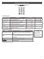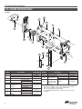
1
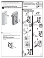
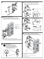
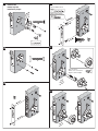
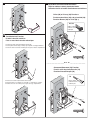
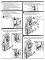
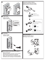
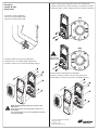
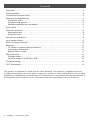
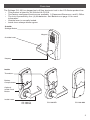
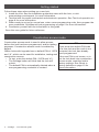
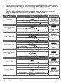
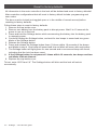
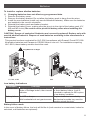
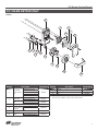
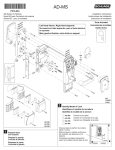
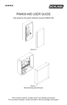
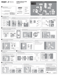
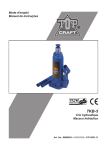
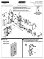
CO-Series for Mortise Serie CO para Cerradura de muesca Séries CO - pour la mortaise P516-267 Instrucciones de instalación de tsi Ou rior te Ex rieur é t Ex Installation Instructions Left Hand Shown, Right Hand Opposite Se muestra el lado izquierdo, para el lado derecho es opuesta Main gauche illustrée, main droite en opposé ide Ins ior er Int ieur r é Int 1 Prepare Door See template. Prepare la puerta Consulte la plantilla. Notice d'installation Tools Included Herramientas incluidas Outils inclus 2 If Insulator Strip is Present, Carefully Remove it Si hay una tira aislante, retírela con cuidado Si la bande isolante est présente, l'enlever soigneusement Préparez la porte Consultez le gabarit. ! OR O OU 3 If Included, Install Door Position Switch (DPS) Si incluido, instale el interruptor para posición de la puerta (DPS) Si inclus, installez le commutateur de position de porte ! Ensure Alignment on Door and Jamb Asegure que la puerta y la jamba estén alineadas Assurez l'alignement avec la porte et le montant 5 9 Verify Tailpiece is Horizontal Correct Correcto Correcte Verifique que la pieza posterior se encuentre en posición horizontal Vérifiez que la queue de pêne soit horizontale 6 9 Incorrect Incorrecto Incorrecte Install Cylinder and Lever Instale el cilindro y la palanca Installez le cylindre et le levier OR O OU Keyed Lever Manija con Llave Levier à clé Interchangeable Cores Núcleos Intercambiables Barillets Interchangeables ide Ins ior r e Int ieur r é t In a a Until Cam Stops Hasta que se detenga la leva Jusqu'à ce que la came s'arrête 4 Align as Shown Alinee como se muestra Alignez comme indiqué Check Lever Handing b See "Rehanding" on back page if pin is not toward latch b Verifique el lado de la palanca c Consulte "Cambiar de lado" en la última página si el pin no apunta hacia el cerrojo c 90˚ Vérifiez le déplacement du levier Consultez le chapitre "Déplacement" si la broche n'est pas orientée vers le loquet LH OR O OU 90˚ e 15° RH d d e ALL TODOS TOUS 7 10 Install Outside Spindle and Standoffs Instale el eje y los distanciadores exteriores Installez l'axe de la poignée et les chevilles nd ck ing Lo ng Ha d ll an Pu tate Ro a e ov . Rem nt 1. or fro olt hb arml latc m Pul fro and ay aw case0°. lockte 18 rotanstall nt. a Rei or fro /0412 arm Ch -473 15 P5 . Rev x2 a x2 x2 a 8 Slide Mortise Lock Into Door Deslice la cerradura de muesca en la puerta Faites glisser la serrure à mortaise dans la porte ¹⁄₄" Wrench Llave Clef 11 a x4 If Present, Route Cable Si hay un cable, instálelo Si présent, placer le câble ⁵⁄₁₆" Wrench Llave Clef x4 b a x1 12 nd Ha ock d gL ll an Pu tate gin Ro an Ch ove . Rem nt 1. or fro olt hb arml latc m Pul fro and ay aw case0°. lockte 18 rotanstall nt. a Rei or fro /0412 arm -473 15 P5 . Rev Note: Refer to Sticker for Mortise Rehanding Refiérase a la calcomanía para cambiar la muesca de lado Consultez l'autocollant pour le déplacement de la mortaise 9 ! Install Bushing and Outside Escutcheon Instale la planchuela exterior y el casquillo Installer la douille et l'entrée de serrure extérieure b a Align Triangles Asegure que los triángulos de orientación estén alineados Assurez-vous du bon alignement des triangles d'orientation de tsi Ou rior te Ex rieur té Ex Stand-offs Align with 2 Holes in Mortise Case Los puntos muertos se alinean con 2 orificios en la caja con muesca Le montage vertical s'aligne avec les 2 trous situés dans le boîtier de mortaise 13 16 Install Plate Instale la placa Installez la plaque Wood / Madera / Bois #16 Metal / Metal / Métal P TO R RIO PE SU UT HA #12-24 a b x2 c a b x2 ¹⁄₈” x2 x2 17 14 x2 Align as Shown Alinee como se muestra Alignez comme indiqué x2 ide Ins ior er Int ieur r é Int 15 18 x2 b ide Ins ior r e Int ieur r é t In a 19 21 Route Wires and Install Inside Escutcheon Dirija los cables e instale la planchuela interior Acheminer les fils et installer l'entrée de serrure intérieure Office (40) or Privacy (50) Functions Funciones de oficina (40) o de privacidad (50) Fonction Bureau (40) ou Privé (50) y 40 / 50 Ribbon Cable Cable de cinta Câble plat 20 Test Mechanical Function Pruebe la función mecánica Faire un essai de la fonction mécanique b a. Rotate lever down and verify that latch retracts fully a. Rote la palanca hacia abajo y verifique que el pestillo se retraiga totalmente a. Tournez le levier vers le bas et vérifiez que le loquet se rétracte complètement a c x2 OR O OU Classroom/Storeroom (70) Function Función salón de clases/almacén (70) Fonction Classe/Entrepôt (70) 70 Battery Cable Cable de batería Câble de pile b. Release lever and verify that latch extends fully b. Suelte la palanca y verifique que el pestillo se extienda por completo b. Relâcher le levier et vérifiez que le loquet s'allonge complètement b a c x2 22 A Follow Steps Below if 40 or 50 Function Only If 70 Function, Go to Step 22 Siga los pasos que se enumeran a continuación si sólo desea las funciones 40 o 50 Si se trata de la funcion 70, vaya al paso 22 Pour les fonctions 40 et 50 seulement, suivez les étapes ci-dessous Pour les fonctions de la 70, passez à l'étape 22 Install Ribbon Cable and DPS Wires Instale el cable plano y los cables DPS Installez le câble plat et les fils du commutateur de position de porte ! 23 24 If Deadbolt, Connect Plug Si es cerrojo de seguridad, conecte la clavija Dans le cas d'un pêne dormant, connectez le bouchon Install Battery Holder and Strap Instale el soporte para la batería y la correa Installer le porte-piles et la sangle Red Wire MUST Be On Left El cable rojo DEBE estar a la izquierda Le fil rouge DOIT être situé à la gauche ! Plug MUST Be on Right El enchufe DEBE estar a la derecha La fiche DOIT être à la droite a b B Tuck Cable and Wires as Shown Ajuste el cable y el resto de los mismos como se exhibe Grouper le câble et les fils comme illustré Cable Cable Câble 25 Wires Alambres Fils Connect Battery Plug and Tuck as Shown Conecte el enchufe de la batería y ajuste como se exhibe Brancher la fiche de la pile et grouper comme illustré 26 Changing the Cylinder’s Tailpiece Cambiar la pieza posterior del cilindro Remplacement de l'embout du cylindre a b 27 Depress Pin De prensa en el pin De presse à la broche Prepare Frame Prepare el marco Préparez le dormant ! Wood / Madera / Bois #16 Tailpiece must be horizontal Debe estar en posición horizontal Doit être horizontale Metal / Metal / Métal #12-24 Classic Everest / Primus 28 Install Strike Instalar el cerrojo Installez la gâche Future Lever Removal Remoción futura de la palanca Démontage ultérieur du levier a b c x2 29 After Installing the Lock, See the User Guide for Setup and Operation. Después de instalar la cerradura, consulte la Guía del usuario para configuración y operación. Après avoir installé la serrure, consultez le guide d'utilisation pour le montage et le fonctionnement. d Rehanding Cambio de lado Déplacement c. Remove Spring Cage, Align Arrow with Latch, and Reinstall c. Retire la caja de resorte, alinee la flecha con el pestillo y reinstale c. Retirez la cage à ressorts, alignez la flèche au loquet et réinstallez a. If Present, Remove USB plug a. Si hay un enchufe USB, retírelo a. Si présent, retirer la prise USB ! LHR RHR ! b. Remove Reader and Cover From Baseplate b. Retire el lector y la cubierta desde la placa base b. Retirer le lecteur et le couvercle de la plaque de base Use Loctite Utilice Loctite Utiliser Loctite d. Reinstall Cover and Reader onto Baseplate d. Vuelva a instalar la cubierta y el lector en la placa base d. Réinstaller le couvercle et le lecteur sur la plaque de base ! NOTE: On Keypad Only Applications, Reader is Not Removable! En las aplicaciones sólo para teclado el lector no se puede quitar Pour les applications sur clavier uniquement, le lecteur n'est pas amovible! ©2012 Schlage Lock Company (877) 671-7011 Printed in U.S.A. P516-267 Rev. 01/12-c *P516-270* P516-270 CO-100 Offline lock user guide Instructions for CO-Series offline locks Para el idioma español, navegue hacia www.schlage.com/support. Pour la portion française, veuillez consulter le site www.schlage.com/support. Contents Overview............................................................................................................................3 Getting started...................................................................................................................4 Construction access mode................................................................................................4 Manual lock programming ......................................................................................................... 5 Credential types.............................................................................................................5 Programming legend......................................................................................................5 Manual programming commands..................................................................................6 Error codes........................................................................................................................7 Test lock operation.............................................................................................................8 Mechanical test..............................................................................................................8 Electronic test................................................................................................................8 Normal lock operation........................................................................................................8 Lock status reports............................................................................................................9 Reset to factory defaults..................................................................................................10 Batteries ......................................................................................................................... 11 To install or replace alkaline batteries.......................................................................... 11 Low battery indications................................................................................................ 11 Battery failure mode..................................................................................................... 11 LED reference..................................................................................................................12 Schlage button.............................................................................................................12 Optional Inside Push Button (IPB)...............................................................................12 Troubleshooting...............................................................................................................12 FCC Statements..............................................................................................................12 This product is compliant of UL 294 and ULC S319 standard. This product’s compliance would be invalidated through the use of any add-on, expansion, memory or other module that has not yet been evaluated for compatibility for use with this UL Listed product, in accordance with the requirements of the Standards UL 294 and ULC S319. This product has been evaluated for ULC-S319 Class I. 2 • Schlage • CO-100 user guide Overview The Schlage CO-100 is a keypad-only off-line electronic lock in the CO-Series product line. • This product is listed for UL 294 and ULC S319. • Two factory-configured functions are available: 1) Classroom/Storeroom, and 2) Office. • The lock is powered by four (4) AA batteries. See Batteries on page 11 for more information. • Outside lever is normally locked. • Inside lever always allows egress. Outside Schlage Button Keypad Outside Lever Keyway Inside Thumbturn Battery Compartment Optional Inside Push Button Inside Lever CO-100-CY CO-100-MS CO-100-MD CO-100-993 3 Getting started Follow these steps when setting up a new lock. 1. Install the lock. See the installation guide that came with the lock, or visit www.schlage.com/support, for more information. 2. Test the lock for proper mechanical and electronic operation. See Test lock operation on page 8 for more information. 3. When ready to set up for normal use, enter a new programming code, then program the user credentials. See Manual lock programming on page 5 for more information. 4. Familiarize yourself with the information in this guide. Save this user guide for future reference. Construction access mode Construction access mode is used to allow access before the lock has been programmed, and for testing purposes. Construction access mode is enabled by default. TIP If you press the default PIN code on a new lock and the code is not Offline locks with keypads have a default PIN of 13579 accepted, the lock has already and “ # ”, which can be used for installation, testing and been programmed. construction access. If the new PIN is not known, or to • To test, enter the default PIN (13579 and “ # ”). put the lock back into construction • The Schlage button will blink and the lock will access mode, reset the lock to unlock. factory settings. See Reset to • The default PIN is automatically deleted when a factory defaults on page 10 for new programming credential is created. more information. 4 • Schlage • CO-100 user guide Manual lock programming Left LED Right LED Credential types Credential type Programming Normal use Toggle Freeze Pass-Through Function Used to program the lock – does not unlock the lock Unlocks the lock momentarily Changes the state of the lock unless in Freeze state Maintains the lock in current state until Freeze PIN is entered again Unlocks a lock momentarily, regardless of state Description Default PIN Five-digit code 97531 and PIN (3 - 6 digits) 13579 and PIN (3 - 6 digits) PIN (3 - 6 digits) PIN (3 - 6 digits) Programming legend Symbol [Programming Code] 1 [PIN] - Description Five-digit code, identical to programming credential code listed in the credential types table. Three- to Six-digit code. A PIN can be any of the PIN code types listed in the credential types table. Asterisk key on the keypad Number keys on the keypad Schlage button TIP Use the same programming code for all locks in the facility. 1 Programming codes such as 1-1-1-1-1 or 1-2-3-4-5 can be easily selected by non-authorized users and should not be used. 5 Manual programming commands LL Commands are confirmed by five alternating green blinks of the Schlage button. LL Programming mode will time out if no entry is made in 20-25 seconds. Timeout is indicated by red blinks of the Schlage button, three left and nine right at the same time. LL The right LED on the Schlage button will blink green to indicate an incorrect entry. To interpret blink patterns, refer to Error codes on page 7. Function Wait For Confirmation1 Wait for Press [Programming Code] Change [Programming Code] New [Programming Code] to stop flashing between each step. [Programming Code] Wait for New [Programming Code] Add Normal Use PIN New [PIN] add another PIN OR to finish [Programming Code] Wait for Add Toggle PIN New [PIN] add another PIN OR to finish [Programming Code] to finish [Programming Code] Add Pass-Through PIN New [PIN] add another PIN OR to finish [PIN] to be deleted to finish [Programming Code] Change Relock Time to stop flashing between each step. Wait for [Programming Code] Delete a PIN to stop flashing between each step. Wait for Add Freeze PIN New [PIN] add another PIN OR to stop flashing between each step. Each button press adds to the total delay time Example: + adds a 10 second delay to finish to stop flashing between each step. Wait for to stop flashing between each step. Wait for to stop flashing between each step. 1 Other lights may show before the final confirmation. Wait for final confirmation before continuing to the next step. 2 Change PIN length is available with firmware version 2.5.0 or higher. 6 • Schlage • CO-100 user guide Manual programming commands LL Commands are confirmed by five alternating green blinks of the Schlage button. LL Programming mode will time out if no entry is made in 20-25 seconds. Timeout is indicated by red blinks of the Schlage button, three left and nine right at the same time. LL The right LED on the Schlage button will blink green to indicate an incorrect entry. To interpret blink patterns, refer to Error codes on page 7. Function Disable/Enable Beeper Wait For Confirmation1 Wait for Press [Programming Code] to disable beeper OR to enable beeper [Programming Code] Change PIN Length 2 Press , , , OR for desired PIN length to finish to stop flashing between each step. Wait for to stop flashing between each step. 1 Other lights may show before the final confirmation. Wait for final confirmation before continuing to the next step. 2 Change PIN length is available with firmware version 2.5.0 or higher. Error codes LL All error codes are indicated on the Schlage button by a solid red LED and a blinking green LED. The number of green blinks indicates the error code. Number of Error code description green blinks 1 Computer programming error (not complete). Too long programming/user code entered. Programming code must be five 2 (5) digits. User code length cannot exceed eight (8) digits. 3 Memory full, too many codes. Delete some codes. 4 Programming code cannot be deleted, only changed. 5 Programming code entries do not match. Programming code not changed. 6 Invalid command. Invalid function code entered. 7 Code not found. Code too short. Programming code length must be five (5) digits. User code 8 minimum length is three (3) digits. 9 Not a unique code. 10 Manual programming not allowed. Error code functions have not been verified by Underwriters Laboratories Inc. 7 Test lock operation If you encounter problems while performing any of the following tests, review the installation guide and correct any problems. Mechanical test 1. Rotate the inside lever or depress the push bar to open the door. Operation should be smooth, and the latch should retract. 2. Insert the key into the keyway and rotate the key and the outside lever to open the door. Operation should be smooth, and the latch should retract. Electronic test 1. Press any number key. The lock will beep. Use the default PIN (13579 and “#”) to verify access. Normal lock operation After PIN credentials have been programmed, enter a PIN to operate the lock as follows: Credential Press a valid PIN Action Green LED will blink and access granted LL The “#” key is used as ENTER key for PINs with fewer than six digits. Default minimum digits is six (6). PIN length may be manually configured so users do not have to push the “#” key (see Change PIN Length2 on page 7). LL If the PIN credential is entered incorrectly, press “ * ” to start over. 8 • Schlage • CO-100 user guide Lock status reports Follow the steps below to obtain lock status reports: LL Lock status reporting is available with firmware version 2.5.0 or higher. LL The left and right Schlage button LEDs will blink red once with each button press, followed by the status indicator as described below. Function / Report Press Press and hold Initiate report mode while pressing Indicator/Report result Wait until only the right Schlage button LED is on to indicate the lock is in report mode and awaiting an entry. If no entry is made, then timeout will occur in 20 seconds. Left LED: Solid green = excellent Blinking green = good Blinking red = low No indicator = critical battery Battery status Once a status is reported, both left and right LEDs will light green, followed by solid green on the right LED only. The right green LED indicates the lock is awaiting another entry. Obtain an additional status report as described below, or press report mode. Function / Report Press Firmware status Hardware status PCB serial number to exit Indicator/Report result Left LED blinks green for the version number Decimal point is indicated by one red blink “Zero” is indicated by two red blinks Left LED blinks green for each number Each number is separated by two red blinks Press after two red blinks to display the next number If no entry is made within 20 seconds of the solid green right LED, then timeout will occur. To exit report mode at any time, press . 9 Reset to factory defaults All information in the main controller in the lock will be deleted and reset to factory defaults! Main controller configurations that will reset to factory default include: programming and user codes. The door must be locked (not toggled open or in the middle of normal access) before resetting to factory defaults. Follow these steps to reset to factory defaults. 1. Remove the top inside cover. 2. Remove one battery from the battery pack to disrupt power. Wait 5 to 10 seconds for power to run out in the lock. 3. Press and hold the Schlage button while reconnecting the battery into the battery pack to resupply power. 4. Continue holding the Schlage button, and wait for two beeps to sound and two green blinks of the Schlage button. 5. Release the Schlage button. 6. Press and release the Schlage button three (3) times within 10 seconds of the beeps and blinks at step 4. One beep will sound and one red blink will occur with each press. 7. The Schlage button will light green for one second and a one-second beep will sound, indicating that the lock has been reset. LL If the Schlage button is not pressed 3 times within 10 seconds, two beeps and two red blinks indicate timeout. 8. Replace the top inside cover. To test, enter 13579 and “#”. The Schlage button will blink and the lock will unlock momentarily. 10 • Schlage • CO-100 user guide Batteries To install or replace alkaline batteries LL 1. 2. 3. Changing batteries does not affect any programmed data. Remove the battery cover. Remove the battery bracket. Do not allow the battery pack to hang from the wires. Install the new batteries (install only new AA Alkaline batteries). Make sure the batteries are installed in the correct orientation. 4. Reinstall the battery pack and battery bracket. 5. Reinstall the battery cover, making sure the plug is to the right of the battery pack (CY, MS and MD locks). Be careful not to pinch the battery wires when installing the battery cover. CAUTION! Danger of explosion if batteries are incorrectly replaced! Replace only with new AA alkaline batteries. Dispose of used batteries according to the manufacturer’s instructions. This product has been evaluated for ULC-S319 compliance with Duracell Procell PC1500 AA alkaline batteries and Panasonic CR2025 lithium coin cell. For installations requiring ULC-S319, these battery models should be used. ! Plug MUST Be on Right CY, MS, & MD 993 Low battery indications Condition Batteries low Indicator Solution After credential PIN is pressed, 9 red Replace batteries immediately blinks of Schlage button, then normal to avoid battery failure. Lock is indicator. intended to operate for 500 cycles in low battery condition. Battery failure No LED or beeps Replace batteries immediately. Valid credentials do not grant access Mechanical override key must be used to unlock the lock. Battery failure mode In the event of battery failure, the lock will fail As-Is (lock remains in current state, locked or unlocked, until batteries are replaced). 11 LED reference Schlage button Condition Access denied Valid PIN entered while lock in Freeze mode Factory default reset Low battery indicator, AA batteries Momentary unsecured access Optional Inside Push Button (IPB) Action Office Mode Press IPB to lock Press IPB to unlock 1 Lights 2 red blinks 12 red blinks indicating lockout One-second solid green with one-second beep 9 left red blinks 1 green blink, then one red blink on relock Lights 1 red blink 1 green blink 1 Unlocking the lock with the IPB will cause the lock to remain unlocked until the IPB is depressed again. Troubleshooting Problem The lock does not function when a valid PIN credential is entered, or the lock beeper does not sound. Possible cause The beeper may be turned off. Solution Use manual programming to enable the beeper (see Disable/Enable Beeper on page 7). Check that the battery or wired power is The battery or wired connected correctly. power may be improperly connected. Check that batteries are inserted in the correct The batteries may be polarity. inserted with incorrect Replace batteries. polarity. Check that the optional IPB through-door ribbon The batteries may be cable is plugged in correctly (if applicable). The depleted. red wire should be on the left and not pinched in If applicable, the IPB the door. through-door ribbon Check that there are no bent pins on the optional cable may not be IPB through-door cable. properly plugged in, or Refer to the installation instructions that came may have bent pins. with the CO-100 lock, or this user guide for details on the above mentioned procedures. FCC Statements This device complies with Part 15 of the FCC Rules. Operation is subject to the following two conditions: 1. this device may not cause harmful interference, and 2. this device must accept any interference received, including interference that may cause undesired operation. Customer Service 1-877-671-7011 www.allegion.com/us © Allegion 2014 Printed in U.S.A. P516-270 Rev. 03/14-e CO-Series Service Manual CO-100-MS KEYPAD ONLY Exterior 39 5 18 44 16 15 37 21 44 21 21 36 35 26 26 27 10 27 Number 5*** 10 15* 16 18* 21 26* 27* a 35 6 Description Baseplate Subassembly, MS Lock Case, Narrow, 1¹⁄₁₆" wide Lock Case, 1¹⁄₄" wide Cylinder Gasket, Baseplate Gasket Kit, Outside Gasket, Reader Lever, Outside Spring Cage Spring Cage, Screws, Spring Cage Outside Gasket, O-Ring Strike Strike Screws, Strike Armor Front Armor Front, MS/ MD Screws, Armor Front Spindle Part Number Number See pg. 39 46928818 46928826 See pg. 48 36a 37a Stand-Offs, MS/MD Baseplate Stand-Offs 39 Wiring Harness 46929162 See pg. 46 See pg. 44 See pg. 44 See pg. 41 * *** a † Classroom/Storeroom Office/Privacy Part Number See pg. 41 See pg. 41 23518392 23518384 Escutcheon, Keypad Only, MS/ CO-100 23599061 MD/993 (Assembly and Screws) Must specify Finish This item only available as part of Exterior Escutcheon Assembly This item only available as part of Door Thickness Kit Must specify Cylinder Type and Handing If using GD/BD Cylinder and Lever preparation, use part number 23599053 44*† See pg. 45 Description CO-Series Service Manual CO-100-MS KEYPAD ONLY Interior 4 1 1 1 12 17 17 1 35 17 38 42 25 25 40 24 Number 1* 4* 12 17 24* 25 Description 4AA Battery Holder & Cover Kit Escutcheon, without IPB Escutcheon, with IPB Batteries, AA Inside Mounting Plate Kit Lever, Inside Spring Cage, Inside 4AA Battery Holder 4AA Battery Strap Screws, Battery Strap (2) Part Number Number 4B-CM 4AA Battery Cover Screw, Battery Cover (1) Escutcheon, Inside Screws, Escutcheon Escutcheon, Inside Screws, Escutcheon 23599327 * a Description Part Number 35a Spindle See pg. 41 38a Spring See pg. 41 40* Rose, Inside 03-042-RHO 42 Hub 23599228 Must specify Finish This item only available as part of Door Thickness Kit 23599335 F206-488 Mounting Plate Screws, Mounting Plate (4) 23599244 03-030 Spring Cage Screws, Spring Cage (2) 23599210 7