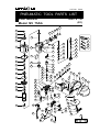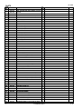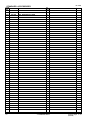
1
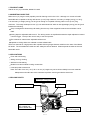
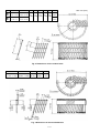
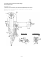
MODEL
NV 75AG
POWER TOOLS
COIL NAILER
NV 75AG
TECHNICAL DATA
AND
SERVICE MANUAL
N
LIST No. E006
Aug. 2002
SPECIFICATIONS AND PARTS ARE SUBJECT TO CHANGE FOR IMPROVEMENT
REMARK:
Throughout this TECHNICAL DATA AND SERVICE MANUAL, a symbol(s)
is(are) used in the place of company name(s) and model name(s) of our
competitor(s). The symbol(s) utilized here is(are) as follows:
Competitors
Symbols Utilized
R
Company Name
Model Name
SENCO
SCN60
CONTENTS
Page
1. PRODUCT NAME ..................................................................................................................... 1
2. MARKETING OBJECTIVE ....................................................................................................... 1
3. APPLICATIONS ........................................................................................................................ 1
4. SELLING POINTS .................................................................................................................... 1
5. SPECIFICATIONS .................................................................................................................... 2
5-1. Specifications ........................................................................................................................... 2
5-2. Nail Selection ........................................................................................................................... 3
5-3. Nail Driving Force .................................................................................................................... 5
6. COMPARISONS WITH SIMILAR PRODUCTS ........................................................................ 6
7. PRECAUTIONS IN SALES PROMOTION ............................................................................... 7
7-1. Instruction Manual ------------------------------------------------------------------------------------------------ 7
7-2. Warning Label ------------------------------------------------------------------------------------------------------ 7
7-3. Related Laws and Regulations -------------------------------------------------------------------------------- 7
7-4. Precautions in Operation ---------------------------------------------------------------------------------------- 8
8. MECHANISM AND OPERATION PRINCIPLE ......................................................................... 9
8-1. Mechanism .............................................................................................................................. 9
8-2. Interchangeability of Parts ...................................................................................................... 11
8-3. Operation Principle ................................................................................................................ 12
9. TROUBLESHOOTING GUIDE ............................................................................................... 14
9-1. Troubleshooting and Correction ............................................................................................. 14
9-2. Possible Causes and Corrections of Air Leakage .................................................................. 19
10. DISASSEMBLY AND REASSEMBLY .................................................................................. 22
10-1. General Precautions in Disassembly and Reassembly ....................................................... 22
10-2. Disassembly and Reassembly of the Output Section .......................................................... 23
10-3. Disassembly and Reassembly of the Control Valve Section ............................................... 25
10-4. Disassembly and Reassembly of the Magazine Section ..................................................... 28
10-5. Disassembly and Reassembly of the Driving Section ......................................................... 31
10-6. Grip Rubber ......................................................................................................................... 35
11. INSPECTION AND CONFIRMATION AFTER REASSEMBLY ............................................ 36
12. STANDARD REPAIR TIME (UNIT) SCHEDULES ............................................................... 37
Assembly Diagram for NV 75AG
1. PRODUCT NAME
Hitachi 75 mm (3") Coil Nailer, Model NV 75AG
2. MARKETING OBJECTIVE
Nails 75 mm (3") long are most popularly used for framing work in the U.S.A. Although our current coil nailer
Model NV 83A is capable of driving nails 83 mm (3-1/4") long maximum, it is heavy in weight (3.5 kg (7.7 lbs.)).
C is also heavy in weight (3.6 kg (7.9 lbs.)) even though it is capable of driving nails 70 mm (2-3/4") long
maximum. The newly developed 75 mm (3") coil nailer Model NV 75AG is ultra-lightweight (2.5 kg (5.5 lbs.)) and
features the following:
"Pop-out magazine" allows easy nail loading from the top of the magazine because the nail holder can be
tilted.
Driving depth is adjustable without tool. The driving section is simplified because the depth adjuster is located
near the trigger. The tip of the nose is easy to see and operate.
The exhaust air outlet is 360˚ adjustable without tool.
Capable of driving either wire-collated or sheet-collated nails.
There is a demand for a high-power nailer capable of driving larger-diameter nails from the users of the Model
NV 65AH. The new Model NV 75AG can also satisfy the above demand. Please expand the sales of the new
Model NV 75AG.
3. APPLICATIONS
Floor and wall framing
Siding, fencing, decking
Wall and roof sheathing
Mobile home and modular housing construction
Crate and pallet construction
Note: The nails of 3.3 mm (.131") dia. x 75 mm (3") length may not be driven reliably into some materials.
Salespersons should instruct the customers to perform a driving test before actual use.
4. SELLING POINTS
Lightweight: 2.5 kg (5.5 lbs.)
Grip rubber
360˚ adjustable exhaust
Tool-less depth
adjustment
Capable of driven both
wire-collated and
sheet-collated nails
Easy top load
pop-out magazine
--- 1 ---
5. SPECIFICATIONS
5-1. Specifications
NV 75AG
Model
Driving system
Reciprocating piston type
Operating pressure
5 --- 8.5 kgf/cm2 (70 --- 120 psi, 4.9 --- 8.3 bar) (Gauge pressure)
Driving speed
3 pcs./sec.
Weight
2.5 kg (5.5 lbs.)
Dimensions
(Length x height x width)
271 mm x 338 mm x 132 mm
(10-11/16" x 13-5/16" x 5-3/16")
Nail feed system
Spiral spring
Nail capacity
200 --- 300 nails (1 coil)
Air consumption
1.8 ltr/cycle at 7 kgf/cm2 (0.064 ft3/cycle at 100 psi, 1.8 ltr/cycle at 6.9 bar)
Air inlet
3/8 NPT thread
Packaging
Corrugated cardboard box
Package dimensions
(Length x height x width)
315 mm x 150 mm x 386 mm
(12-3/8" x 5-7/8" x 15-1/4")
Standard accessories
Eye protector (Code No. 875769) .............................................................. 1
Hex. bar wrench for M6 screw (Code No. 944459) .................................... 1
Hex. bar wrench for M5 screw (Code No. 944458) .................................... 1
Hex. bar wrench for M4 screw (Code No. 943277) .................................... 1
Nose cap (Code No. 883106) ..................................................................... 1
Optional accessories
Pneumatic tool lubricant (1 oz oil feeder) (Code No. 877153)
Pneumatic tool lubricant (4 oz oil feeder) (Code No. 872042)
Pneumatic tool lubricant (1 quart can) (Code No. 876212)
Sequential fire parts set (Code No. 881973)
Case (Code No. 883323)
--- 2 ---
5-2. Nail Selection
The Model NV 75AG utilizes common round-head nails collated by wire or sheet into coils from 200 to 300 pieces.
Applicable nail dimensions are shown below. However, it is recommended to use genuine HITACHI nails to
ensure satisfactory driving quality.
CAUTION: Ensure that nails are as specified in Figs. 1, 2 and 3. Other nails will cause clogging of nails
and subsequent damage to the nailer.
NOTE: Aluminum nails may bend when driven into a hard workpiece. Test before use.
Sheet-collated nails
Min.
7.2 mm
(0.283")
5.7 mm
(0.224")
75 mm (3")
45 mm (1-3/4")
6 mm
(0.236")
Max.
45 mm (1-3/4")
Min.
2.3 mm
(0.090")
2.5 mm
(0.099")
Max.
6 mm
(0.236")
57 mm (2-1/4")
Wire-collated nails
2.5 mm
(0.099")
3.3 mm
(0.131")
Fig. 1 Dimensions of nails
--- 3 ---
L
Type
A
B
d
L1
d1
L2
D1
D2
H
2.5 --- 2.9
45 --- 65
(1-3/4 --- 2-1/2) (0.099 --- 0.113)
65 --- 75
(1-1/2 --- 3)
72
0.7
19
37.5
28
121 (2.835)
(0.028) (0.748) (1.476) (1.102) (4.764)
80
3.1 --- 3.3
(3.150)
(0.120 --- 0.131)
Fig. 2 Dimensions of wire-collated nails
L
d
45 --- 57
(1-3/4 --- 2-1/4)
2.3 --- 2.5
(0.090 --- 0.099)
D1
D2
H
20
118
61.5
(0.787) (4.645) (2.421)
Fig. 3 Dimensions of sheet-collated nails
--- 4 ---
Unit: mm (inch)
5-3. Nail Driving Force
Fig. 4 shows by type of wood and nail the nailer output energy provided by the supply pressure and the nailing
energy required for driving the nail flush. Air pressure which exceeds the intersecting point between the nailer
output energy and the required nailing energy for driving the nail allows the nail to be fully driven.
For example, when driving a nail of 3.3 mm dia. x 75 mm length (0.131" x 3") into a workpiece of hemlock with the
Model NV 75AG, a pressure of about 8 bar (8.2 kgf/cm2, 116 psi) allows the nailer to drive the nail flush with the
wood surface. A pressure beyond this value causes the nail head to be driven below the wood surface.
Fig. 4 should be used as a reference only because those values vary depending on the type of wood, moisture
content, and grain of wood.
Required nailing energy
Nailer output energy
R
NV 83A
Hemlock
NV 75AG
3.3 x 75 mm (.131 x 3")
2.3 x 45 mm (.090 x 1-3/4")
Size of nail mm (in)
NV 65AH
Fig. 4 Required nailing energy and nailer output energy
--- 5 ---
--- 6 ---
5 --- 8.5 kgf/cm2
(70 --- 120 psi)
2.1 kg (4.6 lbs.)
5 --- 8.5 kgf/cm2
(70 --- 120 psi)
2.5 kg (5.5 lbs.)
Operating pressure
Weight
200 --- 300 nails
Nail capacity
Applicable
nails
2.3 mm -- 2.5 mm
(0.090" -- 0.099")
45 mm -- 57 mm
(1-3/4" -- 2-1/4")
2.5 mm -- 3.3 mm
(0.099" -- 0.131")
45 mm -- 75 mm
(1-3/4" -- 3")
Length
Sheet
Diameter
Wire
Tool not required
Direction change of
exhaust air
Collation
Tool not required
Driving depth
adjustment mechanism
Top loading
(Black plastic)
1.8 ltr/cycle
(0.064 ft3/cycle)
Air consumption
at 7 kgf/cm2 (100 psi)
Magazine type
(Material)
1.4 ltr/cycle
(0.049 ft3/cycle)
271 mm x 338 mm x 132 mm
(10-11/13" x 13-5/16" x 5-3/16")
Dimensions
(L x H x W)
Sheet
38 mm -- 65 mm
(1-1/2" -- 2-1/2")
38 mm -- 57 mm
(1-1/2" -- 2-1/4")
2.3 mm -- 2.5 mm
(0.090" -- 0.099")
Wire
Tool not required
Tool not required
Bottom loading
(Clear plastic)
200 --- 300 nails
266 mm x 300 mm x 128 mm
(10-1/2" x 11-13/16" x 5-1/16")
130
Power ratio
100
HITACHI
NV 65AH
Maker and model
HITACHI
NV 75AG
6. COMPARISONS WITH SIMILAR PRODUCTS
200
3.6 kg (7.9 lbs.)
5 --- 7.0 kgf/cm2
(70 --- 100 psi)
R
2.5 mm -- 2.9 mm
(0.099" -- 0.113")
50 mm -- 70 mm
(2" -- 2-3/4")
50 mm -- 83 mm
(2" -- 3-1/4")
Wire
Tool required
Tool not required
Top loading
(Black plastic)
200 --- 350 nails
3.1 ltr/cycle
(0.109 ft3/cycle)
2.5 mm -- 3.3 mm
(0.099" -- 0.131")
Wire
None
Tool required
Bottom loading
(Black plastic)
200 --- 300 nails
2.5 ltr/cycle
(0.088 ft3/cycle)
324 mm x 318 mm x 141 mm
290 mm x 348 mm x 137 mm
(11-13/32" x 13-11/16" x 5-13/32") (12-25/32" x 12-17/32" x 5-9/16")
200
3.5 kg (7.7 lbs.)
5 --- 8.5 kgf/cm2
(70 --- 120 psi)
HITACHI
NV 83A
7. PRECAUTIONS IN SALES PROMOTION
In the interest of promoting the safest and most efficient use of the Model NV 75AG Nailer by all of our customers,
it is very important that at the time of sale the salesperson carefully ensures that the buyer seriously recognizes
the importance of the contents of the Instruction Manual, and fully understands the meaning of the precautions
listed on the Warning Label attached to each tool.
7-1. Instruction Manual
Although every effort is made in each step of design, manufacture, and inspection to provide protection against
safety hazards, the dangers inherent in the use of any pneumatic tool cannot be completely eliminated.
Accordingly, general precautions and suggestions for use of pneumatic tools, and specific precautions and
suggestions for the use of the pneumatic nailer are listed in the Instruction Manual to enhance the safe and
efficient use of the tool by the customer.
Salespersons must be thoroughly familiar with the contents of the Instruction Manual to be able to offer
appropriate guidance to the customers during sales promotion.
7-2. Warning Label
Each Model NV 75AG unit is provided with a Warning Label (illustrated below) which lists basic safety precautions
in its use. Carefully ensure that the customers fully understand and follow these precautions before using the
tool.
7-3. Related Laws and Regulations
As nailers and staplers are designed to instantaneously drive nails and staples, there is an ever-present danger of
misfiring and subsequent possible serious injury. Accordingly, close attention in handling is absolutely necessary
at all times. Carefully ensure that the customer is fully aware of the precautions listed in the Instruction Manual
provided with each unit.
While there are no specific safety regulations, there are related items in various general safety regulations with
which the salespersons should be familiar in order to advise the customer properly. Please check your national
and/or local regulations for applicable items. Some applicable items are outlined below.
The U.S.A:
OSHA
1926.102 Eye and Face Protection
1926.302 Power-Operated Hand Tools
ANSI SNT-101-1993
Portable, Compressed-Air-Actuated,
Fastener Driving Tools-Safety Requirements for
--- 7 ---
7-4. Precautions in Operation
(1) Pay special attention to the pressure, capacity and piping of the air compressor in order to keep the air
pressure supplied to the Model NV 75AG within the range from 5 kgf/cm2 (70 psi, 4.9 bar) to 8.5 kgf/cm2
(120 psi, 8.3 bar). Otherwise, ill effect may be given to the performance, service life and safety of the Model
NV 75AG. (Be sure to install a regulator when using a high-pressure air compressor whose set pressure is
10 kgf/cm2 (140 psi, 9.8 bar) or more. In this case, adjust the air pressure at 8.5 kgf/cm2 (120 psi, 8.3 bar) or
less.)
(2) If dust in the compressed air settles on the sliding portion, the Model NV 75AG will not operate properly.
Lubrication is effective to remove dust and also to prolong the service life of the Model NV 75AG keeping good
performance. It is recommended to lubricate the Model NV 75AG daily. Supply 5-10 drops of lubricant into
the air plug on the Model NV 75AG.
When not in use for an extended period, supply lubricant and perform idle driving two or three times to
lubricate the inside, then apply a thin coat of the lubricant to the steel parts to avoid rusting.
Usable lubricant is specified in the following table. Please recommend the customers to use Hitachi nailer/
tacker oil.
Type of oil
Hitachi Pneumatic Tool Lubricant
Brand or product name
Shell sliding oil, Tonna S32
(Old Tonna T32);
Code No. 877153 (1 oz. oil feeder)
Code No. 874042 (4 oz. oil feeder)
Code No. 876212 (1L (1 quart) can)
(3) Be sure to drain the tank of the compressor securely to prevent deteriorated performance or malfunction of the
Model NV 75AG due to rusting.
(4) Instruct the customers (especially the heavy users) to perform inspection and maintenance securely.
--- 8 ---
8. MECHANISM AND OPERATION PRINCIPLE
8-1. Mechanism
As illustrated in Fig. 7, the Model NV 75AG can be generally divided into four sections:
Output section, control valve section, driving section and magazine section.
The parts of the output section and the control valve section are the same as those of the Model NR 65AK to
allow the use of nails 75 mm (3") long, though the basic construction is the same as the Model NV 65AH.
The parts of the driving section and the magazine section have been newly designed.
Primary differences from the Model NV 65AH are described below.
Output section ................... To make it powerful, the output section is common to the Model NR 65AK except
the following:
Body: There is no interchangeability with the Model NR 65AK since the Model
NV 75AG has an air passage to feed nails. The handle is equipped with
the grip rubber (rubber-ring type) instead of the grip tape. (Note that the
repair part is the conventional grip tape because the grip rubber cannot
be replaced by hand.)
Cylinder: Newly designed.
Piston: Newly designed.
Dust filter: Dust filter is provided between the air inlet cap and the body to
prevent dust from entering the inside (common to the Model
NR 90AC2).
Gasket (B): The shape is changed to install the dust filter (common to the Model
NR 90AC2).
Control valve section .......... The control valve section is common to the Model NR 65AK except the following:
Plunger spring: Common to the Model NV 65AH.
Trigger: Newly designed.
Driving depth adjuster: Located near the trigger to simplify the nose unit.
The tip of the nose is easy to see and operate.
Driving section and magazine section .............The parts of the driving section and the magazine section have
been newly designed.
--- 9 ---
Plunger
Spring [58]
Valve Piston (B) [57]
Valve Bushing
(B) [53]
Top Cover [3]
Exhaust
vent
Exhaust
Cover [5]
Plunger (A) [59]
Valve Bushing
(A) [61]
Head
Valve (A) [10]
Output section
Control valve section
Control valve section
Accumulator
Trigger [39] Body [18]
Piston (H)
(Driver blade)
[17]
Grip rubber
Dust Filter [33]
Cylinder [15]
Cap [34]
Adjuster [44]
Piston
Bumper
[20]
Nose [22]
Driving section
Feeder [28]
Magazine Cover (A) [78]
Guide Lock [87]
Nail Holder [81]
Magazine (A) [75]
n
Nail Guide [89]
ectio
ne s
i
z
a
Mag
Pushing
Lever (A)
[31]
Cover [95]
Section A - A
Nail Guide [89]
Feeder [28]
Feeder Piston [64]
Feed Spring [65]
Fig. 5 Construction
--- 10 ---
8-2. Interchangeability of Parts
The driving section and the magazine section of the Model NV 75AG have been newly designed and there is no
interchangeability with those of the Model NR 65AK. Although most parts of the output section and the control
valve section of the Model NV 75AG are interchangeable with those of the Model NR 65AK, there is no
interchangeability for the parts shown in the table below.
Part
Body [18]
Dust Filter [33]
Gasket (B) [32]
NV 75AG
NR 65AK
Dust Filter [33]
Gasket (B) [32]
Gasket (B)
Grip Tape (A)
Grip rubber
Air passage hole to
feed nails (3 mm dia.)
A
A
Viewed from "A"
Viewed from "A"
Cylinder [15]
Upper end surface of
the cylinder
Upper end surface
of the cylinder
Bore diameter
is concaved.
Plunger Spring [58]
Color: Black
Color: Silver
Plunger (A)
Plunger (A)
Trigger [39]
Color: Yellow
--- 11 ---
Color: Black
8-3. Operation Principle
(1) Prior to nailing (see Fig. 6)
1. When compressed air is supplied to the main body,
Head valve spring
it fills the accumulator (see diagram).
Air passage (A)
Air supply vent
Head valve
2. At the same time, the compressed air flows into the
Accumulator
valve piston lower chamber of the control valve
Cylinder
section, and pushes up the valve piston. Also, the
compressed air flows from the air supply vent,
Valve piston (B)
Control
valve
section
through air passage (A), and into the head valve
upper chamber where it simultaneously pushes
down the head valve and the head valve spring to
seal the upper surface of the head valve and the
cylinder.
Pushing
lever (A)
(2) During nailing (I) (see Fig. 7)
1. When plunger (A) is pushed up by operating both
Fig. 6 Prior to nailing
the pushing lever and trigger (A), the compressed
air in the valve piston lower chamber is exhausted
from the lower part of plunger (A). Then, the valve
piston is pushed down by the compressed air from
the accumulator so that it shuts off the air supply
vent and releases the exhaust valve.
Exhaust cover
Head valve spring
Head valve
2. When the exhaust valve opens, the compressed air
Air passage (A)
Air supply vent
Exhaust valve
Accumulator
Cylinder
[Return air
chamber]
Pushing
lever (A)
the atmosphere through air passage (A).
3. The air pressure applied against the lower surface
Cylinder hole
Piston
Air passage
(B)
in the head valve upper chamber is exhausted into
of the head valve soon exceeds the force of the
Valve piston
Plunger (A)
Trigger (A)
Pushing lever (B)
Nail feeder
section
Feed spring
Feeder Feed piston
head valve spring, and pushes the head valve up.
The head valve is pushed fully upward by the
compressed air, and seals the upper surface of the
exhaust cover and the head valve.
4. When the head valve is pushed up, the
compressed air flows rapidly into the cylinder and
pushes down the piston to drive a nail. At this time,
Fig. 7 During nailing (I)
the compressed air flows through the cylinder hole,
into the return air chamber, through air passage (B),
and into the chamber at the left side of the feed
piston in the nail feeder section. When the air
pressure exceeds the force of the feed spring, the
feeder moves to the right.
--- 12 ---
(3) During nailing (II) (see Fig. 8)
1. When the piston moves down inside the cylinder,
the air below the piston flows through air passage
(C) under the cylinder and is accumulated in the
Cylinder
return air chamber together with the compressed air
Cylinder hole
flowing through the cylinder hole.
[Return air
chamber]
Piston
Air passage (C)
2. When the compressed air in the left chamber of the
feed piston moves the feed piston fully to the right,
the nail feeder (feed pawl) engages the next nail.
Feed piston
Nail feeder
(4) After nailing (see Fig. 9)
1. When the trigger is released, the plunger goes
down, the air supply vent opens, the valve piston
Fig. 8 During nailing (II)
goes up, and the compressed air in the
accumulator passes through air passage (A) into
the head valve upper chamber. The head valve is
then pushed down by the head valve spring and the
air pressure against the upper surface of the head
valve. At the same time, the exhaust valve opens
and the upper chamber of the cylinder is opened to
the atmosphere.
Head valve spring
Air passage (A)
Head valve
Air supply vent
[Accumulator]
2. When the head valve seals the upper surface of the
cylinder, the compressed air accumulated in the
return air chamber passes through air passage (C),
Cylinder
presses on the lower surface of the piston, and
Piston
[Return air
chamber]
Valve piston
Plunger (A)
Trigger
Air passage (C)
forces the piston to return upward to its original
position. Also, the compressed air above the piston
is exhausted through the head valve hole.
3. The compressed air accumulated in the left
chamber of the feed piston passes through air
Feed spring
Feed piston
passage (B), goes into the return air chamber, and
is then exhausted through the nose hole. The feed
Nail feeder
piston is then moved to the left by the force of the
Fig. 9 During return
feed spring, and the feed pawl feeds the next nail
into the ejection port. This completes one full
nailing cycle.
--- 13 ---
9. TROUBLESHOOTING GUIDE
9-1. Troubleshooting and Correction
Problem
1) Nails cannot
be driven.
(
Possible cause
: Most-common cause)
<Nails>
Magazine is not loaded with
specified genuine nails.
Magazine is loaded with
abnormal nails (bent nails,
too large or too small nail
heads, abnormal collation,
others).
Nails or link pieces are
jammed.
Link pieces are deformed or
broken.
<Driving section: Nose, feeder,
feed piston, etc.>
Sliding resistance of the
feed piston is too high.
Nail guide face of the nose
is abnormal (deformed,
burrs or damaged).
Feed spring or feeder spring
is abnormal (damaged or
fatigued).
Feeder is abnormal
(damaged or worn).
Inspection method
Remedy
Check that the magazine is
correctly loaded with
specified nails.
Use specified nails.
Remove the abnormal nails
and load the nailer with
proper nails.
Remove the feed piston
and check the feed
piston sliding surface of
the nose.
Apply grease to the sliding
surface.
Polish the scratched portion
with sandpaper. Replace
the parts.
Check that the driving
section is not abnormal
(burrs, deformed, damaged
or worn).
Deburr the nail guide face.
Correct the deformed part.
Replace the abnormal parts.
Nails are not correctly
loaded in the groove of the
nose.
Check that nails are
correctly loaded in the
groove of the nose.
Load nails in the correct
position in the nose.
Dust sticks to the feeder
sliding portion of the nose,
or lubrication is needed.
Open the nail guide and
perform idle driving to check
the feeder's operation.
Remove dust and then
lubricate the sliding surface.
Adjust the air pressure to
5 --- 8.5 kgf/cm2 (4.9 --- 8.3
bar, 70 --- 120 psi).
Air pressure is too low.
Air passage is clogged
with broken pieces of
piston bumper, etc.
Remove foreign matter.
Replace the piston bumper
with new one.
Body ••• Remove foreign
matter in the return
air chamber.
Nose ••• Remove foreign
matter in the air
passage and the
feed piston
chamber.
Feed piston chamber
contains foreign matter
such as broken pieces of
piston bumper, etc.
--- 14 ---
Problem
1) Nails cannot
be driven.
(continued)
(
Possible cause
: Most-common cause)
Inspection method
Remedy
Air leaks from the gap
between the body and the
nose.
Tighten screws and check
the O-rings.
O-rings are worn or
deformed.
Replace the O-rings.
O-rings need lubrication.
Apply grease or lubricate.
<Nail guide section>
Nail guide face is abnormal
(deformed, burrs or
damaged).
Dust sticks to the inside of
the nail guide groove, or
lubrication is needed.
Check that the nail guide is
not abnormal (worn,
deformed, damaged, etc.).
Correct or replace the parts.
Check the operation of nail
stopper (A) and nail stopper
(B).
Rremove dust and then
lubricate.
Spring is abnormal
(missing, damaged or
fatigued).
The claw ridge section of
the nail stopper is abnormal
(damaged, worn or burrs).
<Magazine section>
<Push lever>
Magazine
Push lever
<Output section: piston,
driver blade, etc.>
Air pressure is too low.
Replace the abnormal parts.
Check that a nail does not
catch on another nail in the
magazine.
Check that a nail does not
catch on some part of the
magazine.
Check the height of the nail
holder.
Collate the nails correctly
and reload the nailer with
them.
Remove burrs or deformed
part. Replace the parts.
Adjust the height of the nail
holder correctly.
Check the operation of the
push lever.
Correct or replace the parts.
Open the nail guide and
perform idle driving to check
that the driver blade is
returned.
Adjust the air pressure to
5 --- 8.5 kgf/cm2 (4.9 --- 8.3
bar, 70 --- 120 psi).
Piston O-ring is abnormal
(worn or damaged).
Replace the piston O-ring.
Piston bumper is abnormal.
Replace the piston bumper.
O-ring in the cylinder is
abnormal (removed,
deformed or damaged).
Reassemble or replace the
parts.
Driver blade is abnormal
(deformed, burrs or
damaged).
Correct or replace the part.
--- 15 ---
Problem
1) Nails cannot
be driven.
(continued)
(
Possible cause
: Most-common cause)
Inspection method
Cylinder inside surface is
abnormal (packed with
dust, or worn).
Check that nails can be
driven at 5 kgf/cm2 (4.9 bar,
70 psi).
Remove dust and then
lubricate.
Replace the part.
Head valve sliding surface
is abnormal (seized or
damaged, or lubrication is
needed).
Perform idle driving to
check the driving
operation.
Replace the part.
Apply grease.
Head valve spring is
abnormal (fatigued or
damaged).
Perform idle driving to check
that the driver blade is not
held in the down position.
Replace the part.
<Control valve section>
Plunger (A), valve piston
(B), valve bushing (A) or
valve bushing (B) is
abnormal (seized or
damaged).
Replace the abnormal part.
Apply grease.
Check that the adjuster is
not raised too high.
Turn the adjuster lower
(lower the pressure).
See item 1).
See item 1).
Driver blade is worn.
Check that the driver blade
tip is not abnormally worn.
Replace the part.
Workpiece is too hard.
Check if a nail is bent even
when driven into soft wood.
Nailer cannot be used
because the material is
beyond its applicable range.
Adjuster is incorrectly set.
Turn the adjuster to the
lowest position and then
drive nails.
Set the adjuster to the
optimum position.
Adjuster is raised too high
for short nails.
Nails are not completely fed
into the injection port.
Unspecified nails are used.
3) Nails cannot
be driven into
the workpiece
completely:
the heads
cannot be
made flush.
Replace the abnormal part.
Disassemble the control
valve section and check the
O-rings.
O-rings or sliding surface
are worn or needs
lubrication.
2) Nails are
driven but
bent.
Remedy
Air pressure is too low.
Workpiece is too hard.
Adjust the air pressure to
5 --- 8.5 kgf/cm2 (4.9 --- 8.3
bar, 70 --- 120 psi).
Check if a nail is bent even
when driven into soft wood.
--- 16 ---
Nailer cannot be used
because the material is
beyond its applicable range.
Problem
3) Nails cannot
be driven into
the workpiece
completely:
the heads
cannot be
made flush.
(continued)
(
Possible cause
: Most-common cause)
Remedy
Driver blade is worn.
Perform idle driving to check
the driver blade is projected
from the nose tip.
Replace the part.
Piston O-ring is abnormal
(worn or damaged).
Disassemble the output
section and check the
piston ring and the inside of
the cylinder for abnormality.
Replace the abnormal part.
Check the sliding surface for
abnormality and lubrication.
Replace the abnormal part.
Apply grease.
Check if the specified nails
are used.
Check the nails as follows.
Use specified nails.
Remove the abnormal nails
and load the nailer with
proper nails.
Cylinder inside surface is
abnormal (worn or rough).
Head valve sliding surface is
abnormal (seized or
damaged, or lubrication is
needed).
4) Nails jam.
Inspection method
<Nails>
Unspecified nails are used.
Abnormal nails are mixed.
Nail heads are too large or
too small.
[Wire-collated nails]
Collating wires are abnormal
(broken, welding failed,
deformed or welding
position failed).
Collating wires are
deformed (deformed in
collation angle or collation
pitch).
[Wire-collated nails]
[Wire-collated nails]
Type
A
B
D
d
Unit: mm (inch)
L2
L1
2.5
(0.099) 19
37.5
6 --- 7.2
(0.236 --- 0.283) 3.3 (0.748) (1.476)
(0.131)
[Sheet-collated nails]
Collating sheets are
abnormal (deformed or
broken).
Nails are removed from the
sheets.
[Sheet-collated nails]
[Sheet-collated nails]
Unit: mm (inch)
D
d
5.7 --- 6.0
2.3 --- 2.5
(0.224 --- 0.236) (0.090 --- 0.099)
--- 17 ---
Problem
4) Nails jam.
(continued)
(
Possible cause
: Most-common cause)
Inspection method
Remedy
<Body: Nail feeding is
incomplete.>
Feeder is worn and the
sliding section is abnormal.
Nail guide face of the nose
or the sliding section of the
feeder is abnormal
(deformed, burrs or
damaged).
Feed spring or feeder spring
is abnormal (damaged,
fatigued or removed).
Open the nail guide and
check the position of the
feeder claw.
Replace the abnormal part.
<Body: Nail guide section>
Nail guide section is
abnormal.
See item "1) Nail guide
section".
See item "1) Nail guide
section".
<Driver blade is not returned
completely.>
See item "1) Output
section: piston, driver
blade, etc.".
Perform idle or actual
driving to check if the driver
blade is returned
completely.
See item "1) Output section:
piston, driver blade, etc.".
Air pressure is too high.
Nails may be jammed if
driven at a high pressure
and high speed. Check
pressure and driving speed.
--- 18 ---
Adjust the air pressure to
5 --- 8.5 kgf/cm2 (4.9 --- 8.3
bar, 70 --- 120 psi).
9-2. Possible Causes and Corrections of Air Leakage
Air leakage repair location
Repair procedure
(1) Check the points of the following parts marked by an asterisk for abnormal condition.
(2) Next, check the seal parts (marked with a double circle) for wear, flaws or damage.
(3) And then, check other places.
b
(A)
a
(H)
(B)
c
d
e
(F) (G)
(C)
Nail feeder section
Control valve section
g
f
h
(E)
(D)
--- 19 ---
(G)
(F)
Cause
Air leakage portion
When the Trigger is turned off
When the Trigger is turned on
(A) Exhaust port
Abnormality in Head Valve (A) [10]
and Cylinder [15] [Wear and
deformation of the sealed face of the
(b) section]
Abnormality in Head Valve O-ring
(P-22) [9] or wear, deformation and/
or breakage of Head Valve (A) [10]
Abnormality (damage) in the Exhaust
Cover [5]
Abnormality in Head Valve (A) [10]
[Wear, deformation and/or breakage
of the section (a)]
* Abnormality in the inner face [the
section (a)] in the Exhaust Cover [5]
[Deformation and dust clogging in
the section (a)]
(B) Exhaust cover
Looseness of the Hex. Socket Hd.
Bolt M5 x 35 [4]
Damage of Gasket (B) [6]
Abnormality in the sealed face of the
Body [18], the Exhaust Cover [5] and
the Cylinder [15]
Looseness of the Nylock High
Tension Bolt M6 x 20 [23]
Scratched and/or the broken O-ring
(P-4) [21]
Abnormality in the sealed faces of
the Body [18] and the Nose [22]
(C) Nose 1
(Feed piston passage)
(D) Nose 2
* Abnormality (breakage and/or
scratches) in O-Ring (S-70) [11] of
the Cylinder Plate [12]
Abnormality in the sealing faces [the
sections (c) and/or (d)] of the
Cylinder Plate [12], Body [18] and/or
the Cylinder [15]
Abnormality (wear, breakage and/or
scratches) in O-ring (P-21) [63] of the
Feed Piston [64], or the wear and/or
deformation of the Nose [22] on the
sliding face
Abnormality (wear, breakage and/or
scratches) in O-ring (P-9) [62] of the
Nose [22], or wear, deformation
and/or scratches of the Feed Piston
[64] on the sliding face
(E) Feed piston
(F) Control valve 1
Abnormality [deformation, crack
and/or damage of the sections (e)
and (f)] in the Piston Bumper [20]
Deformation of Piston (H) [17]
(The deformation of driver blade
abnormality in sealed faces)
The deformation of the face (f) of the
Body [18]
Abnormality (wear, deformation,
breakage and/or scratches) in
O-Ring (S-46) [13]
Abnormality (wear, breakage and/or
scratches) in O-ring (S-4) [48] of
Valve Piston (B) [57]
Abnormality (wear, breakage and/or
scratches) in O-ring (I.D 8.8) [55]
(lower side) of Valve Piston (B) [57]
Abnormality (breakage and/or
scratches) in O-ring (S-18) [54] of
Valve Bushing (B) [53]
* Abnormality in the inner face [the
section (h)] of the valve chamber of
the Body [18]
--- 20 ---
Abnormality (wear, breakage and/or
scratches) in O-ring (I.D 8.8) [55]
(upper side) of Valve Piston (B) [57]
Abnormality (breakage and/or
scratches) in Head Valve O-ring (I.D
16.8) [52] of Valve Bushing (B) [53]
* Abnormality in the upper face [the
section (g)] of the valve chamber of
the Body [18]
Cause
Air leakage portion
When the Trigger is turned off
When the Trigger is turned on
(G) Control valve 2
Abnormality (wear, breakage and/or
scratches) in O-ring (I.D 1.8) [60] of
Plunger (A) [59]
Abnormality (deformation and/or
scratches of the sliding face of
Plunger (A) [59] in Valve Bushing (A)
[61]
Abnormality (wear, breakage and/or
scratches) in O-ring (I.D 11) [56] in
the inside of Valve Piston (B) [57]
Abnormality (deformation and/or
scratches of the sliding face of
Plunger (A) [59] in Valve Piston (B)
[57]
(H) Cap
Loosen Hex. Socket Hd. Bolt M5 x 16 [35].
Broken Gasket (B) [32]
Defective seal surface of the Body [18] or Cap [34]
--- 21 ---
10. DISASSEMBLY AND REASSEMBLY
The items particularly necessary for disassembly and reassembly are described below. The [Bold] numbers in
the descriptions below correspond to the item numbers in the Parts List and exploded assembly diagram.
[CAUTION]
Before disassembly or reassembly, be sure to disconnect the air hose from the nailer (with your finger
released from the trigger) to exhaust all the compressed air and remove all nails.
10-1. General Precautions in Disassembly and Reassembly
Apply grease (Nippeco SEP-3A, Code No. 930035) to the O-rings and O-rings' sliding portions. When
installing the O-rings, be careful not to damage the O-rings and prevent dirt entry.
Oil required: Hitachi pneumatic tool lubricant
1 oz (30 cc) Oil feeder (Code No. 877153)
4 oz (120 cc) Oil feeder (Code No. 874042)
1 quart (1 ltr) Can (Code No. 876212)
If Gasket (B) [6] is damaged, replace it and check that no air is leaking.
Be especially careful to prevent the entry of foreign particles into the control valve section.
Tightening torque for each part
Tightening torque
N•m (kgf•cm, ft-lbs)
Bolt, screw and cap
Nylock High Tension Bolt M6 x 20 ................................. [23]
16.2
1.5 (165
15, 11.9
1.1)
Hex. Socket Hd. Bolt M6 x 12 ....................................... [1]
9.8
0.78 (100
8, 7.2
Hex. Socket Hd. Bolt M5 x 16 ....................................... [35]
6.3
0.5 (65
5, 4.7
0.4)
Hex. Socket Hd. Bolt M5 ............................................... [4] [86]
8.3
0.5 (85
5, 6.2
0.4)
Machine Screw (W/Washer) M5 x 30 ............................ [37]
2.0
0.5 (20
5, 1.5
0.4)
Nylock Hex. Socket Hd. Bolt M4 x 12 ........................... [97]
4.4
0.3 (45
3, 3.3
0.2)
0.6)
Make sure there is no fragment of the Piston Bumper [20] on the passage of the Body [18] and Nose [22]
before replacing the Piston Bumper [20].
--- 22 ---
10-2. Disassembly and Reassembly of the Output Section (See Fig. 10)
[Tool required]
Hex. Socket Hd.
Bolt M6 x 12 [1]
Hex. bar wrench (4 mm)
(a) Disassembly
Plate [2]
Remove the Hex. Socket Hd. Bolts M6 x 12
Top Cover [3]
[1] with a hex. bar wrench (5 mm). Then
Hex. Socket Hd.
Bolt M5 x 35 [4]
the Top Cover [3] can be removed.
Remove the four Hex. Socket Hd. Bolts
M5 x 35 [4] with a hex. bar wrench (4 mm)
Exhaust Cover [5]
and remove the Exhaust Cover [5]. Then
the components of the output section such
as Piston (H) [17], Cylinder [15] and the
6 mm (0.236")
hole
Piston Bumper [20] can be removed.
(b) Reassembly
Gasket (B) [6]
Disassembly procedures should be
followed in the reverse order. Note the
Head Bumper [7]
following points:
Head Value Spring [8]
Apply grease to the inside of the O-ring (I.D
37) [16], O-ring (S-70) [11], O-ring (S-46)
O-Ring (P-22) [9]
[13] and the Cylinder [15] before
reassembly.
Head Valve (A) [10]
Mount Gasket (B) [6] aligning the 6 mm
(0.236") dia. hole with the blowhole of the
O-Ring (S-70) [11]
Body [18].
Cylinder Plate [12]
O-Ring (S-46) [13]
Piston (H) [17]
O-Ring (1AP-48) [14]
Piston Bumper [20]
Blowhole
Cylinder [15]
O-Ring (I.D 37) [16]
Body [18]
Fig. 10 Disassembly and reassembly of the output section
--- 23 ---
Mount the Cylinder Plate [12] to the
Cylinder [15] facing the stopper of the
Cylinder Plate [12] to the Piston Bumper
[20]. When mounting to the Body [18],
fit the rib of the Body [18] into the stopper
groove of the Cylinder Plate [12] (Figs. 11
and 12).
Fig. 11
Stopper of the
Cylinder Plate [12]
Rib of the Body [18]
Fig. 12
Apply grease to the sliding surface A of
the Exhaust Cover [5] and Head Valve (A)
[10] and charge about 0.5 g (0.018 oz) of
O-Ring (P-22) [9]
Groove of the
Exhaust Cover [5]
grease in the groove of the Exhaust Cover
[5] (Fig. 13).
Top Cover [3]
Apply grease to the lip portions B and C
of Head Valve (A) [10] (Fig. 21).
Apply grease to O-Ring (P-22) [9]. Mount
O-Ring (P-22) [9] to Head Valve (A) [10],
C
then mount it to the Exhaust Cover [5].
A
B
Head Valve (A) [10]
Exhaust Cover [5]
Fig. 13
--- 24 ---
10-3. Disassembly and Reassembly of the Control Valve Section (See Fig. 14)
[Tools required]
Roll pin puller (3 mm (0.118 ") dia.)
Body [18]
(a) Disassembly
Roll Pin D3 x 28 [38]
Pull out the Roll Pin D3 x 28 [38] with the roll
pin puller (3 mm (0.118") dia.), remove the
Pushing Lever Guide [40], and the Trigger [39]
Trigger [39]
can be removed.
Roll Pin D3 x 28 [38]
Pushing Lever
Guide [40]
Head Valve O-Ring (I.D 16.8) [52]
Valve Bushing (B) [53]
O-Ring (S-18) [54]
O-Ring (I.D 8.8) [55]
O-Ring (I.D 11) [56]
Valve Piston (B) [57]
O-Ring (S-4) [48]
Plunger Spring [58]
Plunger (A) [59]
O-Ring (I.D 1.8) [60]
Valve Bushing (A) [61]
Fig. 14
--- 25 ---
Pull out the Roll Pin D3 x 28 [38] with the roll
Push
pin puller (3 mm (0.118") dia.), and take out the
control valve in the following manner.
Body [18]
4 to 5 mm (0.157" to 0.198")
dia. bar
1) Remove the Exhaust Cover [5] by following
Head Valve
O-Ring (I.D 16.8)
[52]
the procedure in (1), section 10-2.
2) As shown in Fig. 15, put a 4 to 5 mm (0.157 to
0.197") dia. bar in from the upper side of the
Valve Bushing
(B) [53]
Body [18] and push the top of Valve
Piston (B) [57]. Now, the parts forming the
control valve can be taken out except Valve
Bushing (A) [61] and Head Valve O-Ring
(I.D 16.8) [52].
Valve Piston (B) [57]
When disassembling,
do not pull out this
part by gripping it
with pliers.
Valve Bushing (A) [61]
[CAUTIONS]
Be careful not to damage Valve Piston (B)
[57], Valve Bushings (A) [61] and (B) [53], etc.
Plunger (A) [59]
Do not pull out the end of Plunger (A) [59]
Fig. 15
with pliers.
3) To take out Valve Bushing (B) [53], put a 1.5 to
3 mm (0.059" to 0.118") dia. wire with its end
Valve Bushing (B) [53]
hooked into the hole in the bushing and pull it
out while being careful not to damage the
internal surface of Valve Bushing (B) [53],
Hole
as shown in Fig. 16.
Be careful not to
damage the internal
surface.
Wire with 1.5 to 3 mm dia.
(0.059" to 0.118")
Fig. 16
--- 26 ---
(b) Reassembly
Disassembly procedures should be followed in the reverse order. Note the following points:
Be extremely careful to prevent the entry of foreign particles into the control valve section.
Thoroughly apply grease to the O-Ring (I.D 1.8) [60] on Plunger (A) [59], O-Rings (I.D 11) [56], (S-18) [54]
and (S-4) [48] on Valve Piston (B) [57], and the shaft of Plunger (A) [59] as shown in Fig. 17.
As shown in Fig. 17, install Valve Bushing (A) [61] so that the roll pin groove in Valve Bushing (A) [61] will be
aligned with the roll pin hole in the Body [18]. First, insert a roll pin puller (3 mm (0.118") dia.) into the roll pin
hole. Then, upon confirming that the puller passes through the hole, drive in the Roll Pin D3 x 28 [38].
If an attempt is made to drive the roll pin with force when the roll pin groove in Valve Bushing (A) [61] is not
aligned with the roll pin hole in the Body [18], it will damage the periphery of Valve Bushing (A) [61] and
prevent disassembly or reassembly.
Apply grease to the stem.
Body [18]
Coat the O-ring
groove's shaft
with grease.
Roll pin hole
Roll Pin D3 x 28 [38]
Roll pin
groove
Valve Bushing (A) [61]
Plunger (A) [59]
Valve Bushing (A) [61]
Fig. 17
After assembling, check that Plunger (A) [59] moves smoothly.
--- 27 ---
10-4. Disassembly and Reassembly of the Magazine Section
Tools required
Phillips screwdriver
Roll pin pullers (4 mm dia., 2.5 mm dia.)
Hex. bar wrench (4 mm)
Wrench M5
(1) Disassembly and reassembly of the magazine section
(a) Disassembly (See Fig. 19.)
Loosen the Hex. Socket Hd. Bolt M5 x 20 [86] and the Nylon Nut M5 [69] then remove the Sleeve [70].
Deform Pushing Lever Cover (A) [71] using a flat-blade screwdriver and disengage it from the Nose [22].
Loosen the Machine Screw (W/Washers) M5 x 30 (Black) [37] of the Body [18]. Then the Magazine Ass'y
[98] can be removed.
Engaged.
Deform Pushing Lever Cover (A)
by inserting a flat-blade screwdriver.
Fig. 18
--- 28 ---
(b) Reassembly
Disassembly procedures should be followed in the reverse order. Note the following points.
Bend the tip of the Cover [95] and engage it with the convex portion of Magazine (A) [75]. Hold it with
Pushing Lever Cover (A) [71] positioning the Cover [95] outside Pushing Lever Cover (A) [71].
Nylon Nut M5 [69]
Machine Screw (W/Washers)
M5 x 30 (Black) [37]
Body [18]
Nylon Nut M5 [69]
Pin [76]
Sleeve [70]
Pushing Lever Cover (A) [71]
Magazine (A) [75]
Protector (B) [72]
Feeder Shaft Ring [77]
Pin [76]
Magazine
Cover
(A) [78]
Concave portion
Hex. Socket Hd. Bolt
M5 x 20 [86]
Holder Cap (A) [79]
Nail Holder [81]
O-ring (P-9) [62]
Holder Shaft
(A) [83]
Spring [84]
Roll Pin D2.5 x 12 [82]
Fit the hole of the
Cover [95] beween the convex portion of
Magazine (A) [75] and the concave
portion of Pushing Lever Cover (A) [71].
Ratchet Spring [80]
Fig. 19 Disassembly and reassembly of the magazine section
--- 29 ---
(2) Disassembly and reassembly of nail holder, holder shaft, etc.
(a) Disassembly
Pull out the two Pins [76] with a roll pin puller (4 mm dia.). Then Magazine (A) [75] and Magazine Cover
(A) [78] can be removed. Remove Holder Cap (A) [79] and Roll Pin D2.5 x 12 [82] with a roll pin puller
(2.5 mm dia.) Then O-ring (P-9) [62], Nail Holder [81], Holder Shaft (A) [83] and Spring [84] can be
removed.
(b) Reassembly
Disassembly procedures should be followed in the reverse order. Note the following points.
Mount O-ring (P-9) [62] to the top groove of Holder Shaft (A) [83].
When mounting Holder Shaft (A) [83] to Magazine (A) [75], check that the Spring [84] is inserted
between the concave portion of Magazine (A) [75] and the convex portion of Holder Shaft (A) [83] and
then insert the Pin [76]. (See Fig. 20.)
Check that the Feeder Shaft Rings [77] (2 pcs.) are securely inserted into the grooves of the Pins [76]
(2 pcs.) .
Be careful not to lose the Feeder Shaft Ring [77].
Check the following after reassembly:
The Nail Holder [81] tilts when opening Magazine Cover (A) [78].
The Nail Holder [81] housed in Magazine (A) [75] smoothly when closing Magazine Cover (A) [78].
Convex portion of
Holder Shaft (A) [83]
Nail Holder [81]
Spring [84]
Pin [76]
Concave portion of
Magazine (A) [75]
Fig. 20
--- 30 ---
10-5. Disassembly and Reassembly of the Driving Section
Body [18]
Retaining Ring for
D28 Hole [68]
O-ring (S-46) [13]
Feed Piston Cover [67]
Piston Bumper [20]
Bumper [66]
Feed Spring [65]
Feed Piston [64]
Nose [22]
O-ring (P-21) [63]
O-ring (P-4) [21]
Nylock High Tension
Bolt M6 x 20 [23]
O-ring (P-9) [62]
Plunger (B) [24]
Roll Pin D4 x 16 [25]
Pushing Lever Spring [41]
Feeder Arm (B) [26]
Pushing Lever (C) [42]
Feeder Spring [27]
Adjuster [44]
Feeder [28]
Roll Pin D2 x 16 [43]
Adjuster Spring [45]
Adjsuter Plate (B) [46]
Adjsuter Plate (A) [47]
O-Ring (S-4) [48]
Pushing Lever Cover (B) [30]
Pushing Lever (B) [49]
O-ring (S-5) [50]
Retaining Ring (E-type)
for D3 Shaft [51]
Pushing Lever (A) [31]
Fig. 21 Disassembly and reassembly of the driving section
--- 31 ---
(1) Disassembly and reassembly of Nose [22], Pushing Lever (A) [31] and other parts
(a) Disassembly (See Figs. 21 and 22.)
Remove the four Nylock High Tension Bolts M6 x 20 [23]. Then the Nose [22], Pushing Lever (A) [31] and
other parts can be removed.
(b) Reassembly
Disassembly procedures should be followed in the reverse order. Note the following points.
Apply grease to the O-ring (S-46) [13] and mount it in the groove of the Nose [22].
Align the bent portion of Adjuster Plate (A) [47] with the concave portion of the Pushing Lever Guide [40].
After reassembly, check the components of the pushing lever and the Adjuster [44] move smoothly.
Pushing Lever Guide [40]
Adjuster [44]
Bent portion of Adjuster
Plate (A) [47]
Align the positions.
Fig. 22
(2) Disassembly and reassembly of the adjuster unit
(a) Disassembly (See Fig. 23.)
Remove the Retaining Ring (E-type) for D3 Shaft [51]. Then Pushing Lever (A) [31], Pushing Lever Cover
(B) [30] and the adjuster unit can be removed.
Pull out the Roll Pin D2 x 16 [43]. Then the adjuster unit can be disassembled.
(b) Disassembly
Disassembly procedures should be followed in the reverse order. Note the following points.
Mount Adjuster Plate (A) [47] facing its bent portion toward the Adjuster [44].
Mount Adjuster Plate (B) [46] facing its convex portion toward Adjsuter Plate (A) [47].
--- 32 ---
Adjuster [44]
Adjuster Plate (B) [46]
Adjuster
Spring [45]
Bent portion
Bent portion
Convex portion
Adjuster Plate (A) [47]
Fig. 23
(3) Disassembly and reassembly of Piston Bumper [20], Feeder [28], Feed Piston [64] and other parts. (See Fig. 24.)
(a) Disassembly
Remove the Nose [22] and the parts forming the pushing lever from the output section in accordance with
the procedure in 10-5 (1). Then the Piston Bumper [20] can be removed.
Holding the Feed Piston Cover [67] with fingers, remove the Retaining Ring for D28 Hole [68] with a
retaining ring puller. Then the Feed Piston Cover [67], Bumper [66] and Feed Spring [65] can be removed.
Pull out the Roll Pin D4 x 16 [25] with a roll pin puller (4 mm dia.). Then the Feed Piston [64] and Feeder
Arm (B) [26] can be removed.
Push out Plunger (B) [24] with a roll pin puller (4 mm dia.). Then the Feeder Arm (B) [26], Feeder [28] and
Feed Spring [65] can be removed.
(b) Reassembly
Disassembly procedures should be followed in the reverse order. Note the following points.
Before replacing the Piston Bumper [20], clean the passages of the Body [18] and the Nose [22]
(Fig. 24) and the inside of the feed piston chamber (Fig. 25). If clogged with fragments of the Piston
Bumper [20], the Feed Piston [64] will not work properly.
Piston Bumper [20]
Feeder Arm (B) [26]
Roll Pin D4 x 16 [25]
Split
Groove
Groove
Passage
Body [18]
O-ring
(P-4) [21]
Passage
Nose [22]
O-ring (P-9) [62]
"A" groove
O-Ring (P-21) [63]
Feed piston chamber
Fig. 24
Fig. 25
Apply grease to the O-ring (P-9) [62] and O-ring (P-21) [63] and then assemble them.
Fill the grease with the groove of the Feed Piston [64] as shown in Fig. 25.
--- 33 ---
Apply grease to the O-ring sliding surface of the Feed Piston [64] and the Nose [22]. However, be careful
not to apply too much grease to the "A" surface shown in Fig. 25. Otherwise, the Feed Piston [64]
operates improperly at the low pressure.
Mount the Roll Pin D4 x 16 [25] facing its split toward the magazine as shown in Fig. 25. The amount of
protrusion at both ends must be equal after reassembly (amount of protrusion: 1.5 mm).
Check that the Retaining Ring for D28 Hole [68] is securely inserted into the groove of the Nose [22].
(4) Disassembly and reassembly of Nail Guide [89], Nail Stopper (A) [90], Nail Stopper (B) [92] and other parts
(See Fig. 26.)
Tools required: Flat-blade screwdriver
Hex. bar wrench 3 mm
(a) Disassembly
Remove the Shaft Ring [85] from the Nail Guide Shaft [29] with a flat-blade screwdriver and remove the
Nail Guide Shaft [29]. Then the Nail Guide [89] and other parts can be removed in an assembly.
Remove the Nylock Hex. Socket Hd. Bolt M4 x 12 [97] with a hex. bar wrench 3 mm. Then the Nail Guide
Cover [94], Stopper Spring (A) [91], Stopper Spring (B) [93] and Cover [95] can be removed.
Remove the Shaft Ring [85] from the Guide Lock [87] with a flat-blade screwdriver and pull out the Guide
Lock [87]. Then Nail Stopper (A) [90] and Nail Stopper (B) [92] can be removed.
Nose [22]
Guide Lock [87]
Shaft Ring [85]
Spring [88]
Nail Guide [89]
Nail Stopper (A) [90]
Nail Guide Shaft [29]
Stopper Spring (A) [91]
Nail Stopper (B) [92]
O-ring (P-4) [21]
Stopper Spring (B) [93]
Nail Guide Cover [94]
Shaft Ring [85]
Cover [95]
Nylock Hex. Socket Hd. Bolt M4 x 12 [97]
Sleeve (B) [96]
Fig. 26 Disassembly and reassembly of nail guide, nail stopper (A), nail stopper (B) and other parts
--- 34 ---
(b) Resassembly
Disassembly procedures should be followed in the reverse order. Note the following points.
Before reassembly, remove dust from the groove of the Nail Guide [89].
Fit the convex portions of Nail Stopper (A) [90] and Nail Stopper (B) [92] in the Stopper Spring (A) [91]
and Stopper Spring (B) [93] securely. Be careful not to mistake Stopper Spring (A) [91] for Stopper
Spring (B) [93].
After reassembly, push Nail Stopper (A) [90] and Nail Stopper (B) [92] with fingers to check that they
smoothly return to position.
Mount the Nail Guide Shaft [29] facing its chamfered side upward.
Bend the tip of the Cover [95] and engage it with the convex portion of Magazine (A) [75]. (See Fig. 19.)
10-6. Grip Rubber
The Model NV 75AG is equipped wih the grip-rubber handle that is common to the Model NR 83AA2. However,
the grip rubber is not supplied as a spare part because it is difficult to detach/attach the grip rubber. If
replacement of the grip rubber is required, replace the Body [18] or attach the grip tape.
How to attach the grip tape and the fixing tape
Grip tape (A): Code No. 881768
Fixing tape: Code No. 880407
Grip tape (A) and the fixing tape are adhesive-backed. Start wrapping grip tape (A) near the roll pin hole of the
body and wrap around the body completely. After wrapping, fix grip tape (A) with the fixing tape at both ends of
wrapping (Fig. 27). Note that grip tape (A) and fixing tape cannot be removed once they are adhered.
Fixing tape
Wrapping amount: 1.5 mm to 3 mm
Body
Fixing tape
End of grip tape (A)
End of grip tape (A)
Roll pin hole
Grip tape (A)
Fig. 27
--- 35 ---
11. INSPECTION AND CONFIRMATION AFTER REASSEMBLY
Check that Plunger (A) [59] moves smoothly.
Check that there is no air leakage from each part.
While driving nails with an air pressure of 4.5 kgf/cm2 (63 psi), check that there is no idle driving and bending
of nails.
Note: Before conducting the driving test, turn Adjuster [44] to the deepest position.
Recheck the tightening torque of each screw.
Check that Pushing Lever (A) [31] slides smoothly.
Check that the machine will not operate only by pulling the Trigger [39]. Also check that the machine will not
operate only by depressing Pushing Lever (A) [31].
Push Nail Stopper (A) [90] and Nail Stopper (B) [92] with fingers to check that they smoothly return to position.
Check that the Feed Piston [64] operates properly at 5 kgf/cm2 (70 psi. 4.9 bar) (Open the Nail Guide [89] and
perform idle driving.).
Check that the Trigger [39] moves smoothly.
Check that the Adjuster [44] turns smoothly.
--- 36 ---
12. STANDARD REPAIR TIME (UNIT) SCHEDULES
MODEL
Variable
Fixed
10
20
30
40
50
60 min.
Work Flow
NV 75AG
Cylinder Plate
Exhaust Cover
Cylinder
Top Cover
Piston Bumper
Packing (B)
O-ring x 3
Head Bumper
Head Valve
Spring
O-ring x 2
Head Valve (A)
General Assembly
Pushing Lever
(A)
Pushing Lever
Cover (B)
Adjuster
Pushing
Lever (B)
Pushing
Lever Spring
Pushing
Lever Guide
O-ring x 2
Valve
Bushing (A)
Plunger (A)
Plunger Spring
Valve Piston (B)
Valve Bushing
(B)
O-ring x 7
Body
Piston (H)
O-ring
Feed Piston
O-ring x 2
Feeder Arm (B)
Feed Spring
Feeder
Damper
Feeder Spring
Feed Piston
Cover
Adjustment
(Cylinder, Body,
Valve)
--- 37 ---
Nose
Nail Guide
Nail Stopper (A)
Nail Stopper (B)
Guide Lock
Magazine Ass'y
LIST NO. E006
PNEUMATIC TOOL PARTS LIST
COIL NAILER
Model NV 75AG
2002 • 8 • 30
(E1)
36
35
34
1
33
32
2
3
17
4
503
37
18
58
53
38
504
59
54
38
60
55
19
61
39
6
502
48
52
5
501
57
56
38
7
13
8
68
40
67
20
9
10
11
44
41
45
42
46
43
47
49
48
50
66
65
64
75
62
77
71
14
69
24
85
25
86
70
26
15
27
78
73
23
13
76
72
51
22
12
76
69
21
77
87
29
88
21
28
16
74
63
79
80
81
89
30
90
94
62
91
93
92
85
31
82
83
84
95
98
96
97
62
74
84
PARTS
ITEM
NO.
1
2
NV 75AG
CODE NO.
DESCRIPTION
NO.
USED
949-657
HEX. SOCKET HD. BOLT M6X12 (10 PCS.)
1
880-515
PLATE
1
3
880-514
TOP COVER
1
4
949-822
HEX. SOCKET HD. BOLT M5X35 (10 PCS.)
4
5
883-451
EXHAUST COVER
1
6
883-452
GASKET (B)
1
7
882-914
HEAD BUMPER
1
8
882-913
HEAD VALVE SPRING
1
9
876-796
O-RING (P-22)
1
10
882-912
HEAD VALVE (A)
1
11
878-863
O-RING (S-70)
1
12
882-910
CYLINDER PLATE
1
13
882-874
O-RING (S-46)
2
14
877-368
O-RING (1AP-48)
1
15
883-989
CYLINDER
1
16
883-431
O-RING (I.D 37)
1
17
883-980
PISTON (H)
1
18
883-988
BODY
1
NAME PLATE
1
20
883-432
PISTON BUMPER
1
21
874-436
O-RING (P-4)
2
22
883-981
NOSE
1
23
880-675
NYLOCK HIGH TENSION BOLT M6X20
4
24
883-093
PLUNGER (B)
1
25
949-497
ROLL PIN D4X16 (10 PCS.)
1
26
883-144
FEEDER ARM (B)
1
27
883-143
FEEDER SPRING
1
28
883-092
FEEDER
1
29
883-091
NAIL GUIDE SHAFT
1
30
882-900
PUSHING LEVER COVER (B)
1
31
883-852
PUSHING LEVER (A)
1
32
883-678
GASKET (B)
1
33
883-679
DUST FILTER
1
19
34
881-949
CAP
1
35
949-821
HEX. SOCKET HD. BOLT M5X16 (10 PCS.)
3
36
872-035
DUST CAP
1
37
880-881
MACHINE SCREW (W/WASHERS) M5X30 (BLACK)
1
38
949-865
ROLL PIN D3X28 (10 PCS.)
3
39
883-990
TRIGGER
1
40
882-885
PUSHING LEVER GUIDE
1
41
882-892
PUSHING LEVER SPRING
1
42
882-891
PUSHING LEVER (C)
1
43
880-093
ROLL PIN D2X16
1
44
883-982
ADJUSTER
1
45
882-890
ADJUSTER SPRING
1
46
882-887
ADJUSTER PLATE (B)
1
47
882-886
ADJUSTER PLATE (A)
1
48
981-317
O-RING (S-4)
2
49
882-888
PUSHING LEVER (B)
1
50
872-822
O-RING (S-5)
1
51
872-971
RETAINING RING (E-TYPE) FOR D3 SHAFT
1
--- 2 ---
* ALTERNATIVE PARTS
REMARKS
8 -- 02
PARTS
ITEM
NO.
52
NV 75AG
CODE NO.
NO.
USED
DESCRIPTION
877-699
HEAD VALVE O-RING (I.D 16.8)
1
53
878-881
VALVE BUSHING (B)
1
54
878-885
O-RING (S-18)
1
55
878-925
O-RING (I.D 8.8)
2
56
878-887
O-RING (I.D 11)
1
57
880-672
VALVE PISTON (B)
1
58
878-884
PLUNGER SPRING
1
59
880-673
PLUNGER (A)
1
60
878-888
O-RING (I.D 1.8)
1
61
880-671
VALVE BUSHING (A)
1
62
872-645
O-RING (P-9)
2
63
880-330
O-RING (P-21)
1
64
883-300
FEED PISTON
1
65
882-883
FEED SPRING
1
66
877-711
BUMPER
1
67
880-331
FEED PISTON COVER
1
68
939-555
RETAINING RING FOR D28 HOLE (10 PCS.)
1
69
877-371
NYLON NUT M5
2
70
882-907
SLEEVE
1
71
883-853
PUSHING LEVER COVER (A)
1
72
882-901
PROTECTOR (B)
1
73
883-106
NOSE CAP (A)
1
74
878-184
WARNING LABEL
1
75
883-984
MAGAZINE (A)
1
76
883-111
PIN
2
77
877-826
FEEDER SHAFT RING
2
78
883-985
MAGAZINE COVER (A)
1
79
883-987
HOLDER CAP (A)
1
80
880-398
RATCHET SPRING
1
81
880-503
NAIL HOLDER
1
82
878-791
ROLL PIN D2.5X12
1
83
883-986
HOLDER SHAFT (A)
1
84
881-826
SPRING
1
85
880-319
SHAFT RING
2
86
949-757
HEX. SOCKET HD. BOLT M5X20 (10 PCS.)
1
87
880-318
GUIDE LOCK
1
88
880-446
SPRING
1
89
883-392
NAIL GUIDE
1
90
883-085
NAIL STOPPER (A)
1
91
883-088
STOPPER SPRING (A)
1
92
883-086
NAIL STOPPER (B)
1
93
883-087
STOPPER SPRING (B)
1
94
883-089
NAIL GUIDE COVER
1
95
883-393
COVER
1
96
882-881
SLEEVE (B)
2
97
880-630
NYLOCK HEX. SOCKET HD. BOLT M4X12
2
98
883-983
MAGAZINE ASS’Y
1
8 -- 02
* ALTERNATIVE PARTS
REMARKS
INCLUD.62,74-84
--- 3 ---
NV 75AG
STANDARD ACCESSORIES
ITEM
NO.
501
CODE NO.
DESCRIPTION
NO.
USED
875-769
EYE PROTECTOR
1
502
943-277
HEX. BAR WRENCH 3MM
1
503
944-458
HEX. BAR WRENCH 4MM
1
504
944-459
HEX. BAR WRENCH 5MM
1
--- 4 ---
* ALTERNATIVE PARTS
REMARKS
Printed in Japan
(020830N)
8 -- 02