1
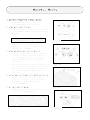
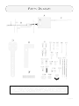
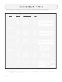
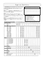
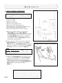
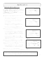
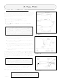
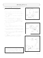
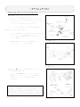
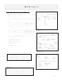
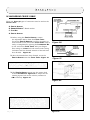
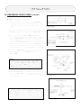
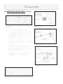
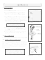
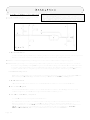
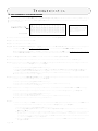
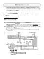
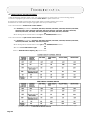
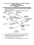
WorldCruise
ELECTRIC CRUISE CONTROL
KIT# 250-1311
INSTALLATION & OWNER’S MANUAL
CONTENTS
Safety Procedures.........................................
Helpful Hints................................................
Parts List......................................................
Parts Diagram...............................................
Supplemental Parts.......................................
Switch Settings.............................................
Installation ..................................................
Troubleshooting.............................................
Operating Instructions..................................
2
3
4
5
6
7
8
20
23
Form# 2976
Rev B 2/00
SAFETY PROCEDURES
The WorldCruise is a microprocessor based Cruise Control. It is designed for ease of installation and can be used with most
cars, light trucks and vans. Carefully follow the installation procedures in this manual for best results.
DO NOT INSTALL THIS SYSTEM ON A DIESEL POWERED VEHICLE WHICH HAS A MANUAL TRANSMISSION WITHOUT A
DISENGAGEMENT SWITCH (Kit# 250-4206) ON THE CLUTCH PEDAL ASSEMBLY.
Your vehicle must have a VSS (Vehicle Speed Signal) wire or an available signal generator for installation of the WorldCruise.
Please consult vendor’s application guide.
Throughout the instructions there are WARNINGS, CAUTIONS, AND NOTES that are meant to make it easier for you to
install the WorldCruise on your vehicle and make it safer to use. We have gathered these tips from people across the country
who have informed us of their problems and solutions. Even with all these reports from the field, we cannot cover every condition which you might encounter, there are just too many different vehicle makes and models. We do our best to tell you how to
handle most vehicles, but we must Depend on Your Good Judgement for dealing with the rest.
Therefore, we believe you can understand why we strongly urge you to think carefully about what could happen to you, your
passengers, and your vehicle if you use any tools, parts, fastening methods, routing or procedures which are not described in
this manual.
There is NO drain on the battery if the control switch is left on. The WorldCruise needs no regular service.
WARNING
Failure to follow the instruction manual could not only cause the WorldCruise to work
improperly, but could cause the throttle to hang up, possibly causing damage to your
vehicle and injury and/or death to you and your passengers.
WARNING
If you question the applications of the WorldCruise, please consult the applicable application
guide. Only install on approved applications.
The product described in this manual was developed, manufactured and tested in line with recognized technical standards
and is in compliance with the fundamental safety requirements.
Nevertheless, there are residual risks!
It is therefore important to read this manual before installing and connecting the product. Keep the manual in a place that is
readily accessible at all times.
Throttle Adapter
In order to cover certain vehicles with a universal cruise control, we have designed throttle adapters for performance and
safety. Consult current Application Guides and Vehicle Technical Information Guides to see if your vehicle needs a Throttle
Adapter before you install the WorldCruise. If an adapter is listed, it must be used with that application.
Target Group and Qualified Installation
This description is intended for those persons who install the product in the motor vehicle. In order to be able to operate
properly, the WorldCruise must be correctly installed. The system may therefore be installed and wired by persons who know
and have understood the installation instructions of this manual and are familiar with automotive electrical and mechanical
systems. Installation by nonqualified personnel can lead to injury to the driver or third parties, or damage to property or the
environment.
Modifications to the product
The WorldCruise is designed, manufactured and tested with due regard to safety and reliability.
Modifying or tampering with the product can affect its safety. This can lead to death, serious or slight injury to the driver or
third parties, or damage to property or the environment. For this reason, the product must not be modified or tampered with!
Inform the user
Hand the Operating Manual for the cruise to the user. The Operation Manual is an integral part of the product!
If the cruise has not been fitted with a clutch switch, Please inform the user that the engine speed briefly increases when the
function is switched off via the clutch.
WARNING
The information in this manual has been carefully compiled through actual vehicle testing and manufacturers service manual
research and to the best of our ability is accurate. However, we do not warrant the accuracy of this information against
changes in vehicle design, the use or misuse of this information or typographical errors. It is the responsibility of the installer
to verify the signal and color on the wire attachments prior to and after the installation of the WorldCruise to assure proper
operation. We do not accept any responsibility for damage to the vehicle or injury to its occupants caused by the use of this
information. Improper installation and/or connection to the incorrect wires could cause WorldCruise or vehicle malfunction,
component damage, and or personal injury for you and/or your passengers.
Page 2
HELPFUL HINTS
1. BEFORE STARTING INSTALLATION:
Familiarize yourself with the Installation
Instructions and WorldCruise components.
2. MATING CONNECTORS:
A. When disconnecting, hold connector and press
the lock downward while pulling connectors apart.
Figure A
CAUTION
Do not pull on wires.
Figure A
B. When inserting, push mating connectors
together until locking mechanisms are firmly
locked together. Figure B
3. AIRBAG AND ANTI-THEFT RADIO:
A. If vehicle is equipped with an Anti-Theft Radio,
the radio code must be written down prior to
disconnecting battery cable. The code must be
reentered when the negative battery cable is
reinstalled.
B. If vehicle is equipped with an Airbag (SRS), it is
advisable to disconnect the negative battery cable.
However, remember that some vehicles retain
power to the airbag system when battery is
disconnected.
Figure B
4. REMOVAL OF NEGATIVE BATTERY CABLE:
Disconnect the negative battery cable before
installing the WorldCruise for safety precautions.
Remember to reconnect the cable after
installation. Figure C
5. ACCESSORY POWER:
Figure C
When installing the special terminal into the fuse
panel of vehicle, See Figure D.
WARNING
Failure to follow the instruction manual could
not only cause the WorldCruise to work improperly,
but could cause the throttle to hang up, possibly
causing damage to your vehicle and injury and/or
death to you and your passengers.
Figure D
Page 3
PARTS LIST
ITEM
SERVICE
PART #
DESCRIPTION
QTY
A
250-3779
CRUISE MODULE
1
B
250-3695
CRUISE HARNESS
1
C
250-3607
CRUISE CABLE
1
D
250-3702
MODULE BRACKET
1
E
250-3700
CABLE BRACKET
1
F
250-3425
CONVOLUTED TUBING (58”)
1
G
250-3947
HARDWARE PACKAGE
1
1
2
3
4
5
6
7
8
9
10
11
12
13
14
15
16
17
18
19
20
21
22
2
4
1
2
2
1
1
1
1
1
10
1
1
1
1
1
1
2
2
1
1
1
MODULE BOLT
SELF-THREADING BOLT (M6 X 19)
BEAD CHAIN
BEAD CHAIN CONNECTOR
CONNECTOR COVER
LOOP CABLE (67MM)
LOOP CABLE (81MM)
THREE BEAD CONNECTOR
EYELET CONNECTOR
TIE STRAP (102MM)
TIE STRAP (190MM)
TUBE CLAMP (10MM)
FLAG NUT (THREADED TUBE CLAMP)
M5 BOLT (M5-.8 X 10)
M5 BOLT (M5-.8 X 20)
M5 NUT
LOCKNUT (NYLON INSERT, M5-.8)
LOCKWASHER NUT (1/4-20)
PLAIN WASHER
SNAP-IN ADAPTER
COTTER PIN (2MM X 16MM)
SEALING PUTTY
Use CLUTCH DISENGAGEMENT SWITCH (Kit# 250-4206) for manual transmission vehicle when the Dark Blue TACH
wire cannot be obtained from vehicle or fails to disengage the WorldCruise.
Service Parts are available to replace any part in this kit (See Service Part Numbers above).
Additional Hardware is available on Page 6.
Page 4
PARTS DIAGRAM
WARNING
Failure to follow the instruction manual could not only cause the WorldCruise to work
improperly, but could cause the throttle to hang up, possibly causing damage to your
vehicle And injury and/or death to you and your passengers.
Page 5
SUPPLEMENTAL PARTS
The following parts are available for your convenience and may simplify the installation of your WorldCruiuse.
Contact your local dealer or ROSTRA representative for details.
SERVICE
PART #
ITEM
DESCRIPTION
QTY
A. LOOP CABLES
A
250-2248
250-3089
250-2250
250-2249
250-2251
1.83”
2.62”
2.91”
3.20”
3.81”
(47MM)
(67MM)
(74MM)
(81MM)
(97MM)
10
10
10
10
10
1.65”
2.74”
3.03”
3.53”
5.93”
(42MM)
(70MM)
(77MM)
(90MM)
(151MM)
10
10
10
10
10
B. T-BAR ADAPTERS
B
250-2252
250-2247
250-2253
250-2254
250-4248
C. STUD-CLIP
CABLE
W
250-2261
250-4255B
250-4242
250-2260
C
1.00”
1.25”
2.40”
2.80”
(25MM)
(32MM)
(61MM)
(71MM)
10
10
10
10
D. THROTTLE COUPLERS*
250-4291
250-4292
D
M6
M8
10
10
3/16” (5MM)
1/4” (6MM)
5/16” (8MM)
3/8” (10MM)
1/2” (13MM)
10
10
10
10
10
E. TUBE CLAMPS
250-2255
250-2256
250-2257
250-2258
250-2259
MISCELLANEOUS
F.
G.
E
F
250-3440
250-2262
G
GM™ HATCLIP
10
PEDAL BRACKET ASSEMBLY** 1
* The THROTTLE COUPLER Sets (250-4291 and 250-4292) come complete with THROTTLE COUPLER, STUD CAP and
ELASTOMER RETAINER.
** The PEDAL BRACKET ASSEMBLY (250-2262) comes complete with a PEDAL BRACKET, a SELF-LOCKING PIN, an M5-.8
BOLT, an M5 NUT and two (2) PLAIN WASHERS.
Page 6
X
12
SWITCH SETTINGS
The CRUISE MODULE must be programmed for the vehicle on which it
is installed. The twelve (12) programming switches must be set
according to the chart below in order for the WorldCruise to operate
properly. Figure 1
The twelve (12) programming switches are located under
the Black rubber grommet on top of the CRUISE MODULE.
NOTE 1: Both the VSS (Gray) and TACH (Dark Blue) wires must be
connected. (If the Gray wire is not used, an auxiliary road speed
source must be used.) See Page 18.
NOTE 2: If using an “Open Circuit” control switch with the
WorldCruise, Switch number seven (7) will have to be OFF. If you are
unsure as to whether the control switch is “Open Circuit” or “Closed
Circuit”, look at the label of the packaging in which the switch came,
or See Page 22.
NOTE 3: If any of the twelve (12) switches need to be changed after
installation of the WorldCruise, the control switch and the vehicle
ignition must be in the OFF position; this is to allow the WorldCruise
to RESET.
Figure 1
Figure 1 represents the twelve (12) programming
switches for a vehicle characterized by:
Switch (1 & 2) High Gain,
Switch (3 , 4, 11 & 12) 4000 PPM,
Switch (5 & 6) 4 Cylinder, Low,
Switch (10) Square Wave Input,
Switch (9) Manual Transmission
Switch (8) High Set-Up Timer, and
Switch (7) Closed Circuit Control Switch
Page 7
INSTALLATION
I. CRUISE MODULE MOUNTING
NOTE
DO NOT MOUNT THE CRUISE MODULE IN THE
FOLLOWING AREAS:
*
*
*
*
*
*
*
*
Under the fender.
Under the vehicle.
Directly to the engine.
With the cable pointed down.
Near sharp, hot or moving objects.
Near ignition coil [No closer than 255mm (10”)].
In the passenger compartment (Noise).
Where it will interfere with service checks.
A. Select a possible location to mount your
CRUISE MODULE, set the CRUISE MODULE
unmounted in that area. The reason for leaving
the CRUISE MODULE unmounted is to make sure
the CRUISE HARNESS will reach the passenger
compartment and the CRUISE CABLE will reach
the throttle attaching point.
Figure 2
B. Once you have selected a location, install the
MODULE BRACKET to the bottom of the CRUISE
MODULE with the two (2) MODULE BOLTS provided.
It may be necessary to cut and bend the MODULE
BRACKET to achieve a custom fit. Figure 2
NOTE
DO NOT OVERTIGHTEN! DAMAGE TO THE
CRUISE MODULE WILL OCCUR IF THE BOLTS
ARE OVERTIGHTENED.
C. Mount the CRUISE MODULE in the spot you have
selected using two (2) of the SELF-THREADING
BOLTS provided in the kit. Be sure to set the
programming switches located underneath the
rubber grommet on top of the CRUISE MODULE (See
Page 7) before mounting the WorldCruise.
Figure 3
Page 8
Figure 3
WARNING
Failure to follow the instruction manual could
not only cause the WorldCruise to work improperly,
but could cause the throttle to hang up, possibly
causing damage to your vehicle and injury and/or
death to you and your passengers.
INSTALLATION
II. MEASURING THROTTLE CABLE TRAVEL
THIS IS A VERY IMPORTANT STEP. FAILURE TO
DETERMINE THROTTLE CABLE TRAVEL COULD CAUSE
DAMAGE TO YOUR VEHICLE AND/OR WorldCruise.
MEASURE ONLY WITH THE ENGINE OFF. The CRUISE
CABLE moves 41mm (1-5/8”).
To measure throttle travel, measure the distance from Position
“A” (Idle) to Position “B” (Wide Open Throttle).
Figure 4
A. Make a mark on the throttle cable when the throttle
is in the idle position. Figure 4
B. Depress accelerator pedal and make a mark on the
throttle cable when the throttle is in the wide open
position. Figure 5
C. Measure the Distance “C” between the two marks.
Figure 6 If the distance is greater than 41mm (1-5/8”),
go to Page 9; If it is less, go to Step D.
D. If the throttle travel is less than 41mm (1-5/8”), you
must add length to the CRUISE CABLE to provide slack.
Figure 5
NOTE: Slack is the distance the CRUISE CABLE moves before the
throttle starts to move.
E. Slide a CONNECTOR COVER on the throttle LOOP CABLE and
on the CRUISE CABLE. Install a BEAD CHAIN CONNECTOR on
the end of the LOOP CABLE and on the end of the CRUISE
CABLE. The BEAD CHAIN CONNECTOR may need to be spread
slightly for cable to enter.
F. Install the end bead of the BEAD CHAIN in each BEAD
CHAIN CONNECTOR with a bead (or beads) between them to
add additional length. The beads inside the BEAD CHAIN
CONNECTORS do not add length.
Figure 6
NOTE: Each bead of the BEAD CHAIN added between the BEAD
CHAIN CONNECTORS will give you 7mm (.28”) of slack.
Example: If your throttle travels 35mm (1-3/8”), you will need to
add one (1) bead between connectors. Figure 7
G. After the BEAD CHAIN is installed, lightly crimp the BEAD
CHAIN CONNECTORS without pinching the cables and center
the CONNECTOR COVERS over the BEAD CHAIN CONNECTORS.
NOTE: You must always use the CONNECTOR COVERS.
Figure 7
After determining your throttle cable travel, continue to Section III.
WARNING
Failure to follow the instruction manual could not only cause the WorldCruise to work
improperly, but could cause the throttle to hang up, possibly causing damage to your vehicle
and injury and/or death to you and your passengers.
Page 9
INSTALLATION
III. ATTACHING CRUISE CABLE TO THROTTLE
This section will cover the proper ways to use the hardware available. Each
method contains sample illustrations showing how the connector is used in
an actual installation. It must be noted, however, that you should have an
understanding of how each attachment method works so that a proper
installation is achieved.
There are five (5) different types of throttle connections.
A. Pulley Assembly Using The LOOP CABLE
B. Pulley Assembly Using T-BAR ADAPTER (See Page 6)
C. Pedal Attachment.
D. Ford™ Throttle
E. General Motors™ and Chrysler™ Throttle Using THREE BEAD
CONNECTOR
NOTE
When using the BEAD CHAIN CONNECTOR to connect the BEAD CHAIN
to the CRUISE CABLE you must always use the CONNECTOR COVER.
Figure 8 Failure to use the CONNECTOR COVER could possibly
cause the BEAD CHAIN or CRUISE CABLE to hang in the BEAD CHAIN
CONNECTOR causing the throttle to be held in a partially open
position. This condition may even occur when the cruise control
is not being used.
Figure 8
A. Pulley Assembly Using The LOOP CABLE
1. On some vehicles it may be necessary to remove the air cleaner to
access the throttle pulley segment.
2. Set the pulley segment in an OPEN throttle position, and remove
the throttle cable from the pulley.
3. Hold the LOOP CABLE between the holes in each side of the pulley.
Slide the barrel at the end of the throttle cable through the slotted
hole, then through the LOOP CABLE and into the second hole.
Figure 9
4. Connect the LOOP CABLE to the CRUISE CABLE using the BEAD CHAIN
CONNECTOR as follows:
Slide a CONNECTOR COVER on the LOOP CABLE. Install a BEAD CHAIN CONNECTOR
onto the LOOP CABLE and then onto the CRUISE CABLE. BEAD CHAIN CONNECTOR
may need to be spread slightly for cables to enter. After the BEAD CHAIN
CONNECTOR is installed, lightly crimp the connector without pinching the
cables. Then slide the CONNECTOR COVER over the center of the BEAD CHAIN
CONNECTOR.
Figure 9
NOTE
You must always use the CONNECTOR COVER. Failure to do so
could possibly cause the LOOP CABLE or the CRUISE CABLE to hang
in the BEAD CHAIN CONNECTOR causing the throttle to be held in a
partially open position.
5. To secure the LOOP CABLE to the throttle cable, punch a small hole
in the CONNECTOR COVER and slide the TIE STRAP (102MM) through
the hole and secure to the throttle cable. Figure 10
NOTE: Firmly tighten the TIE STRAP (102MM) and remove excess to
prevent possible throttle interference.
Page 10
Figure 10
WARNING
If the LOOP CABLE is not secured to the existing throttle
cable, it could come out of the pulley segment possibly
causing the throttle to be held in a partially open position.
INSTALLATION
III. ATTACHING CRUISE CABLE TO THROTTLE
(Continued)
B. Pulley Assembly (Dual) Using The T-BAR ADAPTER
1. Remove air cleaner to expose the dual pulley segments.
2. Find the blank anchor that is located above the throttle
anchor. Follow the instructions for anchoring the CRUISE
CABLE, See Page 14.
3. Attach a BEAD CHAIN CONNECTOR onto the CRUISE CABLE.
Figure 11
4. Attach the T-BAR ADAPTER to the top pulley segment.
Slide the CONNECTOR COVER onto the T-BAR ADAPTER.
5. Attach the T-BAR ADAPTER to the BEAD CHAIN CONNECTOR
Make sure to slide the CONNECTOR COVER over the BEAD
CHAIN CONNECTOR. Figure 12
Figure 11
C. Pedal Attachment
1. Select a TUBE CLAMP that fits around the top of the
accelerator pedal shaft. Make sure the tabs of the TUBE
CLAMP point away from the bulkhead.
2. Attach the BEAD CHAIN to the CRUISE CABLE with a BEAD
CHAIN CONNECTOR. Make sure to use a CONNECTOR COVER.
3. After you determine the length of BEAD CHAIN needed to
attach to the accelerator pedal shaft, cut BEAD CHAIN and
attach to the EYELET CONNECTOR. Make sure to use a
CONNECTOR COVER.
4. Put M5 BOLT through the holes in the TUBE CLAMP.
Slide the EYELET CONNECTOR over the bolt. Thread
LOCKNUT onto the bolt and tighten. Figure 13
WARNING
Failure to follow the instruction manual could
not only cause the WorldCruise to work improperly,
but could cause the throttle to hang up, possibly
causing damage to your vehicle and injury and/or
death to you and your passengers.
Figure 12
Figure 13
Page 11
INSTALLATION
III. ATTACHING CRUISE CABLE TO THROTTLE
(Continued)
D. Ford™ Throttle
1. Select a TUBE CLAMP that fits the throttle cable.
Make sure the tabs of the TUBE CLAMP point away
from the carburetor or air throttle, this will prevent
the throttle from hanging. Figure 14
2. Attach CRUISE CABLE to the EYELET CONNECTOR.
NOTE: Use the CONNECTOR COVER.
3. Put the M5 BOLT through the holes in the TUBE
CLAMP. Slide the EYELET CONNECTOR over the
bolt. Thread the LOCKNUT onto the bolt and
tighten. Figure 14
4. Figure 15 is an example of a Ford™ Throttle
connection using the TUBE CLAMP.
Figure 14
Figure 15
E. General Motors™ and Chrysler™ Throttle using
THREE BEAD CONNECTOR.
1. Most General Motors™ vehicles and many
Chrysler™ vehicles can use the THREE BEAD
CONNECTOR to attach the CRUISE CABLE.
Figure 16
WARNING
Failure to follow the instruction manual could
not only cause the WorldCruise to work improperly,
but could cause the throttle to hang up, possibly
causing damage to your vehicle and injury and/or
death to you and your passengers.
Page 12
Figure 16
INSTALLATION
III. ATTACHING CRUISE CABLE TO THROTTLE (Continued)
E. General Motors™ and Chrysler™ Throttle using THREE
BEAD CONNECTOR. (Continued)
2. Attach the BEAD CHAIN to the THREE BEAD CONNECTOR.
Secure beads by folding the metal tabs. Figure 17
3. Remove clip or pin which retains throttle cable (and
washer if provided) and install THREE BEAD CONNECTOR
on the same side of throttle cable that the CRUISE
CABLE will be anchored (this is necessary so that
CRUISE CABLE and throttle cable will not cross).
4. The THREE BEAD CONNECTOR may need to be bent so
that it clears the throttle cable. Figure 18 Use the
TIE STRAP (102MM) to hold the THREE BEAD CONNECTOR
to the sleeve of the throttle cable. Figure 18
Figure 17
5. When the THREE BEAD CONNECTOR is properly used,
the following parts will be required:
THREE BEAD CONNECTOR
CONNECTOR COVER
BEAD CHAIN CONNECTOR
BEAD CHAIN
See Figure 19
Figure 18
NOTE
After the CRUISE CABLE has been attached,
manually move the throttle to assure the
CRUISE CABLE does not hang up on any part
of the vehicle.
WARNING
Failure to follow the instruction manual could
not only cause the WorldCruise to work improperly,
but could cause the throttle to hang up, possibly
causing damage to your vehicle and injury and/or
death to you and your passengers.
Figure 19
Page 13
INSTALLATION
IV. ANCHORING CRUISE CABLE
There are three (3) types of connectors used to anchor the
CRUISE CABLE:
A. SNAP-IN ADAPTER
B. General Motors™ Blank Anchor
C. FLAG NUT
A. SNAP-IN ADAPTER
1. Before using the SNAP-IN ADAPTER, remove
the Adjustable Sleeve from the CRUISE CABLE.
To use the SNAP-IN ADAPTER, it will be necessary to
form threads on the end of the CRUISE CABLE. This is
easily accomplished by placing the LOCKWASHER NUT
on the end of the CRUISE CABLE with your fingers.
Then using an 11mm box end wrench and turning
clockwise until the desired amount of threads have
been formed. Figure 20
2. After the threads have been formed, screw the
SNAP-IN ADAPTER onto the CRUISE CABLE. Figure 21
Figure 20
Figure 21
NOTE
Insulation on the CRUISE CABLE must extend past
the end of the SNAP-IN ADAPTER on all applications.
3. The SNAP-IN ADAPTER snaps into the square hole
of the CABLE BRACKET Figure 22 or snaps into an
existing square hole on the vehicle (common on
GM™ vehicles). Figure 23
Figure 22
WARNING
Failure to follow the instruction manual could
not only cause the WorldCruise to work improperly,
but could cause the throttle to hang up, possibly
causing damage to your vehicle and injury and/or
death to you and your passengers.
Page 14
Figure 23
INSTALLATION
IV. ANCHORING CRUISE CABLE
(CONTINUED)
B. General Motors™ Blank Anchor
1. To locate the blank anchor on General Motors™
vehicles, it is necessary to remove the air cleaner.
The blank anchor is located above the throttle
anchor.
Figure 24
2. This anchor is hollow except at one end. Use a
6.4mm (.25”) bit drill as shown in Figure 24.
3. Before using the LOCKWASHER NUT, remove the
Adjustable sleeve from the CRUISE CABLE. Then use
the LOCKWASHER NUT to form threads on the end of
the CRUISE CABLE. This is easily accomplished by
placing the LOCKWASHER NUT on the end of the CRUISE
CABLE with your fingers. Then use an 11mm box end
wrench and turn clockwise until the desired amount
of threads have been formed. Figure 20, Page 14
Figure 25
4. Insert the CRUISE CABLE through the blank anchor
and thread the other LOCKWASHER NUT in place.
Figure 25
NOTE
If you do not use the other LOCKWASHER NUT,
install a TUBE CLAMP 152mm-178mm from the
anchor point. Figure 26 This will keep the
CRUISE CABLE from backing out of the anchor.
5. The LOCKWASHER NUT can also be used if there is a
pre-existing 6.4mm hole in a bracket on the vehicle
or if it is possible to drill a 6.4mm hole in a bracket
on the vehicle.
Figure 26
WARNING
Failure to follow the instruction manual could
not only cause the WorldCruise to work improperly,
but could cause the throttle to hang up, possibly
causing damage to your vehicle and injury and/or
death to you and your passengers.
Figure 27
Page 15
INSTALLATION
IV. ANCHORING CRUISE CABLE
(CONTINUED)
CAUTION
When using the FLAG NUT on the CRUISE CABLE
the Adjustable Sleeve MUST be REMOVED.
When using a TUBE CLAMP on the CRUISE CABLE
the adjustable sleeve MUST be USED to prevent
slippage or binding of cable.
C. FLAG NUT
Figure 28
1. Before using the FLAG NUT, it will be
necessary to form threads on the end of the
CRUISE CABLE. This is easily accomplished by
placing the LOCKWASHER NUT on the end of the
CRUISE CABLE with your fingers. Then use an
11mm box end wrench and turn clockwise
until the desired amount of threads have been
formed. Figure 20, Page 14
2. After the threads have been formed, screw the
FLAG NUT onto the CRUISE CABLE. Figure 28
3. The FLAG NUT may be used to anchor the
CRUISE CABLE to the existing throttle cable
bracket. Figure 29 In some cases there is an
existing hole, in other cases you can drill a
5mm (.20”) hole in the bracket.
Figure 29
4. The FLAG NUT may also be used to anchor the
CRUISE CABLE using the CABLE BRACKET.
Figure 30
Figure 30
WARNING
Failure to follow the instruction manual could
not only cause the WorldCruise to work improperly,
but could cause the throttle to hang up, possibly
causing damage to your vehicle and injury and/or
death to you and your passengers.
Page 16
INSTALLATION
V. CRUISE HARNESS
A. Push Rubber Grommet securely into place on the cover of
the CRUISE MODULE. Figure 31
B. Straighten the CRUISE HARNESS and find the 2- & 4-pin
mating connectors. Seperate the 2- & 4-pin connectors.
A small screwdriver may be needed (See K in Figure 34).
C. CRUISE HARNESS needs a 19mm (.75”) hole to pass through
bulkhead. You may find one nearby, such as the speedometer
cable hole or a small one you can file larger. If you find the
right size hole in the right place, remove vehicle grommet. If
not, drill, saw, or punch a 19mm hole in bulkhead. A hole a
few millimeters to the left or slightly higher than the steering
column is usually a good place. Figure 32
NOTE
Check inside before drilling, sawing, or filing
so you don’t damage anything.
Black
Figure 31
D. From engine side, pass the 2- & 4-pin connectors through
hole. If you do not hook up the Dark Blue TACH wire and
the Gray VSS wire under the hood, pass them through to
the inside of the vehicle, also.
E. Reattach the 2- & 4-pin mating connectors and make the
necessary wire connections. (See Page 18 for wiring
instructions)
VI. SEALING BULKHEAD
Seal hole in bulkhead with SEALING PUTTY as shown in Figure 32.
VII. CONTROL SWITCH INSTALLATION
If your cruise control switch is the type which clamps on the turn
signal lever, requires cutting the turn signal lever, or is mounted on
the instrument panel, follow the instructions packaged with it. If
you have a switch which replaces the complete original equipment
turn signal lever, remove the existing lever and install the cruise
control switch and lever assembly as instructed in the vehicle
shop service manual.
Figure 32
WARNING
Failure to follow the instruction manual could
not only cause the WorldCruise to work improperly,
but could cause the throttle to hang up, possibly
causing damage to your vehicle and injury and/or
death to you and your passengers.
Figure 33
Page 17
INSTALLATION
VIII. WIRING ATTACHMENTS TO VEHICLE
CAUTION
Utilize Figure 34 to make the necessary wiring
harness connections to your vehicle.
Before making any wiring connections, be sure to disconnect
your vehicle’s negative battery cable to avoid electrical shock
and/or damage to the the vehicle’s electrical system.
Figure 34
A. Black Ground Wire
In order to find a good ground for the cruise system, find a vehicle ground point which is a clean unpainted
metal surface. If the cruise control does not “see” ground at all times, it will not function.
NOTE: Do not use the engine as a grounding point. Do not use the cable bracket as a gounding point.
NOTE: To find a place to get electrical power you will need to ground one lead of your test light or volt-ohmmeter.
Find electrical ground by turning ON the ignition switch and touching one lead to a “Hot” fused terminal at
fuse panel; touch other lead to unpainted metal part of vehicle. The metal you touch, if it makes continuity,
is ground. The bracket for the parking brake lever is usually a good ground. Turn the ignition OFF.
B. Brown Accessory Power
Find a fuse at the fuse panel that supplies power to one of the vehicles accessories. It should be +12 volts
when the key is ON and zero (0) volts when the key is OFF or in the START (CRANK) position.
C. Red Brake Positive
“Hot” side of brake switch: Use the wire at the brake switch connector with constant +12 volts
D. Violet Brake Negative
“Cold” side of brake switch: Use the wire at the brake switch connector with zero (0) resistance when
brake is not pressed, and +12 volts or open resistance when brake is pressed.
E. Dark Blue Tachometer (TACH) Wire
The TACH function is a safety feature of the WorldCruise.
If a vehicle with an automatic transmission is accidentally “knocked” into neutral while the vehicle is in
motion and the WorldCruise is active, the TACH wire, when connected, will disengage the WorldCruise
before engine over-rev. If the TACH wire is not “hooked-up”, the cruise control will function; however the
TACH over-rev safety feature will be inactive; this is dangerous and not recommended. ROSTRA
PRECISION CONTROLS, INC. always recommends the attachment of the TACH wire.
Page 18
INSTALLATION
E. Dark Blue Tachometer (TACH) Wire
(CONTINUED)
On a vehicle with a manual transmission, the TACH wire connection is not required only when CLUTCH
DISENGAGEMENT SWITCH (Kit# 250-4206) has been installed; this will take into acount the TACH over-rev
safety feature. The TACH wire should be grounded when using a clutch disengagement switch to ensure
that the wire does not introduce “trashy” signals into the system.
In order to locate the TACH signal, consult a Vehicle Shop Manual, our Vehicle Technical Guide
(ROSTRA Form# 2482), try our Fax-Back System at (910) 610-4191, call our Technical Service
Department at (910) 277-1828, Fax us at (910) 276-3759 (USA) or visit us on the web at
www.rostra.com.
F. Gray Vehicle Speed Sensor (VSS) Wire
The Gray Vehicle Speed Signal (VSS) wire is how the WorldCruise “knows” how fast the vehicle is moving.
The Pulses Per Mile/Kilometer (PPM/PPK) are a characteristic of the vehicle and must be set accordingly
(See Page 7). If VSS cannot be located on the vehicle then an auxiliary road speed sensor must be used
[SIGNAL GENERATOR or MAGNET & COIL PICK-UP KIT (KIT# 250-4165)]. If you use an auxiliary speed sensor, plug
it into auxiliary speed sensor connector (G in Figure 34) and trim the Gray VSS wire as not to pick-up any
stray signals.
In order to locate the VSS signal, consult a Vehicle Shop Manual, our Vehicle Technical Guide
(ROSTRA Form# 2482), try our Fax-Back System at (910) 610-4191, call our Technical Service
Department at (910) 277-1828, Fax us at (910) 276-3759 (USA) or visit us on the web at
www.rostra.com.
G. Auxiliary Speed Sensor Connector
This connector is utilized when the Gray VSS wire is not used as the vehicle speed source. Both ROSTRA
[SIGNAL GENERATOR and MAGNET & COIL PICK-UP KIT (KIT# 250-4165)] have a mating connector which plugs
right into the wiring harness.
H. 4-Pin Switch Connector
This connector is utilized by the control switch. All ROSTRA control switches contain a mating connector
which plugs right into the main wiring harness.
J. 2-Pin Switch Connector
This connector is used in conjunction with the 4-Pin Switch Connector (H in Figure 34). The 2-Pin
Switch Connector (J in Figure 34) is utilized by control switches which require an additional power and
ground source such as those containing an LED indicator light or ROSTRA Radio Frequency (RF) models.
K. Bulkhead Connectors
These connectors simplify the installation of the wiring harness through the engine bulkhead (firewall).
Simply disconnect the connectors, run them through any 19mm (.75”) hole in the firewall (preferably near
the steering column), and reconnect them once inside the passenger compartment.
WARNING
Failure to follow the instruction manual could not only cause the WorldCruise to work
improperly, but could cause the throttle to hang up, possibly causing damage to your vehicle
and injury and/or death to you and your passengers.
Page 19
TROUBLESHOOTING
IX. SELF DIAGNOSTIC TESTING PROCEDURE
The WorldCruise is equipped with a Self Diagnostic Light Emitting Diode (LED) located underneath the rubber grommet on top of
the CRUSE MODULE. Utilize the following Self Diagnostic Procedure to troubleshoot your cruise control if it does not function
properly once installed.
DIAGNOSTIC LED
The twelve (12) programming
switches and diagnostic LED
are located under the Black
rubber grommet on top of
the CRUISE MODULE.
FIGURE 35
Carefully follow the procedures below to enter your cruise control into Self Diagnostic Mode.
Step 1: Turn the cruise control switch OFF.
Step 2: Turn the ignition to the OFF position.
Step 3
Closed Circuit Control Switch (See Page 22): Press and hold the RESUME/ACCEL button while you turn the ignition
switch to the ON position without starting the engine. Now release the the RESUME/ACCEL slide switch.
Open Circuit Control Switch (See Page 22): Turn the ignition switch to the ON position without starting the engine,
hold the RESUME/ACCEL button down while you turn the cruise control switch to the ON position.
Step 4: The Diagnostic LED should be OFF at this time. You are now in Self Diagnostic Mode.
Continue to follow the procedures below to test your cruise control switch, brake switch connections and VSS signal.
Step 5: Press and Release the SET/COAST button. The LED should light each time the button is pressed and go out when it is
released. If so, continue to Step 6; if not, go to Step 5a.
a. Check steps to entering Diagnostic Mode and test again.
b. Check Programming Switch# 12. It should be ON for a Normally Closed Circuit Control Switch and OFF for a
Normally Open Circuit Control Switch. (See Page 22): If set incorrectly, reset and reenter Diagnostic Mode.
c. Check power to the CRUISE MODULE if none of the diagnostic commands are functioning.
d. Check Cruise Control Switch (See Page 22).
Step 6: Press and release the RESUME/ACCEL button. The LED should light each time the button is pressed and go out when it
is released. If so, continue to Step 7; if not, go to Step 6a.
a. Check steps to entering Diagnostic Mode and test again.
b. Check power to the CRUISE MODULE if none of the diagnostic commands are functioning.
c. Check Cruise Control Switch (See Page 22).
Step 7: You will need a second person to help you perform this test. Press and release the Brake Pedal. The LED should light
each time the brake is pressed and go out when it is released. If so, continue to Step 8; if not, go to Step 7a.
a. Check steps to entering Diagnostic Mode and test again.
b. Check power to the Red Brake Positive wire.
c. Check power to the CRUISE MODULE if none of the diagnostic commands are functioning.
d. Check Brake Switch Connector and wiring to brake switch.
Step 8:
a. Vehicle’s own computer as VSS source: Roll the vehicle at least two (2) meters forward or backward, the LED should
flash and continue to flash at the same rate. If so, continue to Step 9; if not, go to Step 8ai.
i. Check steps to entering Diagnostic Mode and test again.
ii. Check Programming Switch# 10. It should be ON for Square Wave Input. If set incorrectly, reset and reenter
Diagnostic Mode.
iii. Some vehicles need to be pushed more than two (2) meters. In that case, raise one (1) of the vehicle drive wheels
(both drive wheels on a limited slip differential) and block the non drive wheels. Use a support stand for safety.
Spin the drive wheel by hand as fast as possible. The LED should flash and continue to flash at the same rate. If
so, continue to Step 9; if not, go to Step 8aiv.
iv. Either your VSS wire is incorrect or your connection is bad. Inpect your VSS connection and reenter Self
Diagnostic Mode.
Page 20
TROUBLESHOOTING
b. Auxiliary Speed Sensor ([SIGNAL GENERATOR or MAGNET & COIL PICK-UP KIT (KIT# 250-4165)] Raise one (1) of
the vehicle drive wheels (both drive wheels on a limited slip differential) and block the non drive wheels. Use a support
stand for safety. Spin the drive wheel by hand as fast as possible (You must spin the wheel at least 4.8 KPH (3 MPH) or
faster in order to test an auxiliary speed signal.) The LED should flash and continue to flash at the same rate. If so,
continue to Step 9; if not, go to Step 8bi.
i. Check steps to entering Diagnostic Mode and test again.
ii. Check Programming Switch# 10. It should be OFF for Sine Wave Input. If set incorrectly,
reset and reenter Diagnostic Mode.
Step 9: Your WorldCruise has successfully passed the Self Diagnostic Testing Procedure. If it still does not function, test your
TACH signal.
X. TACH SIGNAL TESTING PROCEDURE
Step 1: Turn the cruise control switch OFF.
Step 2: Turn the ignition to the OFF position.
Step 3
Closed Circuit Control Switch (See Page 22): Press and hold the RESUME/ACCEL button while you turn the ignition
switch to the ON position and start the engine. Now release the the RESUME/ACCEL slide switch.
Open Circuit Control Switch (See Page 22): Turn the ignition switch to the ON position and start the engine, hold
the RESUME/ACCEL button down while you turn the cruise control switch to the ON position.
Step 4: The Diagnostic LED should be flashing. Rev the engine, the LED should flash faster at higher RPM’s. If so, your TACH
signal is valid, if not, go to Step 4a.
a. Check steps to entering Diagnostic Mode and test again.
b. Either your TACH wire is incorrect or your connection is bad. Inspect your TACH connection and reenter Self
Diagnostic Mode.
General Wiring Diagram
WorldCruise System
Figure 36
Page 21
TROUBLESHOOTING
XI. CONTROL SWITCH TESTING PROCEDURE
Utilize the following continuity charts to test your control switch if you suspect that it is not functioning properly.
You need to unplug the 8-pin connector from the CRUISE MODULE to perform these tests.
1. Ground the test light lead and verify that the light works by probing a known power source.
2. Follow the test charts below using the appropriate chart for your control switch.
Your control switch is a Closed Circuit Control Switch if:
1. Its ROSTRA part number is 250-3002, 250-3018, 250-3020, 250-3021, 250-3026, 250-3032, 250-3084,
250-3091, 250- 3100, 250-3120, 250-3125, 250-3126, 250-3127, 250-3133, 250-3167, 250-3168,
250-3169, 250-3175, 250-3180, 250-3194, 250-3304, 250-3328, 250-3421, 250-3446
OR
2. You must push the control button to the left for the RESUME/ACCEL function.
Your control switch is an Open Circuit Control Switch if:
1. Its ROSTRA part number is 250-3357, 250-3358, 250-3443, 250-3444, 250-3592, 250-3593, 250-3632,
250-3633, 250-3594, 250-3595, 250-3742, 250-3743.
OR
2. You must push the control button to the right for the RESUME/ACCEL function.
OR
3. It has a Green LED Indicator Light.
OR
4. It is a ROSTRA Radio Frequency (RF) control switch.
The CRANK or START IGNITION SWITCH POSITION refers to the momentary state when the key starts the engine
just before it returns to the RUN IGNITION SWITCH POSITION.
Page 22
OPERATING INSTRUCTIONS
XII. WorldCruise
OPERATING INSTRUCTIONS
ON: To operate the WorldCruise, turn the power button
ON. (Green LED Indicator will light, if equipped.) Wait
three (3) seconds before setting speed.
SET SPEED: To engage system, drive at any speed
above 50 KPH (33 MPH), press SET/COAST or press
RESUME/ACCEL and release, then remove your foot
from the accelerator pedal. Automatic control will be at
the speed of the vehicle when the button is released
plus or minus 3 KPH (1-1/2 MPH) Press accelerator
and speed will increase, release accelerator and you
will return to set speed.
NOTE: The RESUME/ACCEL button will SET the
WorldCruise without pressing the SET
button first.
COAST: Press and Hold the SET/COAST button and
your speed will decrease. Release button and speed of
vehicle at time button is released will be new set speed
if above 50 KPH (33 MPH).
ACCEL: Press and hold the RESUME/ACCEL button
and your speed will increase. Release button and you
will have a new higher set speed.
TAP-UP: You can gradually increase your speed by
quickly pressing and releasing the RESUME/ ACCEL
button. Each time you press and release the button your
speed will increase by 1-1/2 to 5 KPH (2 to 3 MPH).
TAP-DOWN: You can gradually decrease your speed by
quickly pressing and releasing the SET/COAST button.
Each time you press and release the button your speed
will decrease by 1-1/2 to 5 KPH (2 to 3 MPH).
DISENGAGE: Depress brake pedal slightly; automatic
speed control will cease but set speed will stay in the
system’s memory. Also, you can disengage by pressing
button to OFF position, but this erases the memory. To
get the RESUME feature to work again, you must first
set a speed. Turning OFF the ignition also clears the
system’s memory.
RESUME: After disengaging system with brake or clutch,
return to SET speed by driving above 50 KPH (33 MPH).
Then press RESUME/ACCEL button and release it. If
acceleration rate is faster or slower than you like, drive to
within a few KPH (MPH) of your set speed, then press and
release the RESUME/ACCEL button.
THINGS YOU SHOULD KNOW
ABOUT YOUR WorldCruise
The performance of the WorldCruise is dependent upon the
condition of the engine, its size and even by the type of
emission control equipment it has. Driving at higher altitudes will have an effect on WorldCruise performance.
Under normal conditions and with proper switch settings,
speed should be controlled within plus or minus 3 KPH
(1-1/2 MPH). There may be situations; however, which
make it seem as if the WorldCruise is not capable of functioning accurately, such as an extra heavy load, a very
steep hill, or a severe headwind.
CAUTION: Do not use the WorldCruise on a slippery
road nor in heavy traffic.
CAUTION: (Manual Transmission) While driving with
the WorldCruise ON, do not shift to neutral
without depressing the clutch pedal, as this
may cause engine racing or overreving. If this
happens, depress the clutch pedal or turn
OFF the main Cruise Control Switch
immediately.
OUR QUALIFIED EXPERT TECHNICAL SERVICE DEPARTMENT IS
READY TO ASSIST YOU WITH ANY QUESTIONS OR PROBLEMS
THAT YOU MAY HAVE ABOUT OUR PRODUCT. CONTACT US VIA
PHONE AT (910) 277-1828 (USA) OR FAX AT (910) 276-3759 (USA).
Page 23
Rostra Precision Controls, Inc.
Global Automotive Accessories Group
2519 Dana Drive
Laurinburg, NC 28352-4000
www.rostra.com
Certified QS 9000/ISO 9001
Made in the U.S.A.