1
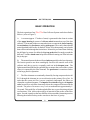
R
DUST CONTROL SYSTEMS
SERVICE
GUIDE
Manufactured by:
JOE TIPTON, INC.
JOE TIPTON, INC.
TABLE OF CONTENTS
INTRODUCTION AND INITIAL STARTUP
INTRODUCTION
Basic Operation
INITIAL STARTUP
Blower Assembly
Speed Adjustment
Direction of Rotation
Compressed Air Supply
Pneumatic Timer
Electric Timer
Page
Page
Page
Page
Page
Page
Page
Page
Page
1
2
4
4
4
7
7
7
10
Page
Page
Page
Page
Page
12
13
14
15
16
REPLACEMENT PARTS
BLOWER ASSEMBLY
DUST COLLECTOR PICKUP POTS
TIMERS
DEFLECTOR ASSEMBLY
MISCELLANEOUS PARTS
MAINTENANCE
ROUTINE MAINTENANCE
TROUBLE SHOOTING
Page 23
Page 24
JOE TIPTON, INC.
INTRODUCTION
The Filter/Clone Dust Collector is an advanced design utilizing a system of barrier
filters located in the vortex of a cyclone. The use of the cyclone to centrifugally
separate the heavier material from the fine dust has demonstrated a significant
reduction in loading of the filter elements while at the same time allowing for an
increase in volume of material collected.
In order to maintain the level of performance that is designed into each Filter/Clone
Dust Collector, one should fully understand how the unit operates, so that
periodic inspections and repairs can be performed. This manual is intended to
explain to the user proper servicing techniques and offers special trouble shooting
suggestions.
BASIC SPECIFICATIONS
Listed in the table below are the basic specifications of the various models of
Filter/Clone units currently being used on blasthole drills.
MAX. BLOWAIR CAPACITY
(SCFM)
Filter/Clone
MODEL
AIR FLOW
(SCFM)
APPROX.
HP
NO.
FILTERS
SUCTION
HOSE DIA.
BLOWER
WHEEL
200
SIZE 1
600
1.7
1
4"
17" DIA.
300
SIZE 1.5
900
2.5
1
5"
17" DIA.
700
1000
SIZE 2R4
SIZE 3SB
2000
3000
4.5
11.0
4
4
6" or 7"
8"
18" DIA.
20" DIA.
1000
FC-3000
3000
11.0
4
8"
20" DIA.
1150
1300
FC-3600
SIZE 4SB
3600
4500
13.0
15.0
4
6
8"
8" or 10"
20" DIA. +
19.5" DIA.
1500
1700
FC-4500
SIZE 5SB
4500
5000
17.0
20.0
6
7
8" or 10" 19.5" DIA.
10" or 12" 365-BL
2400
3000
SIZE 7SB
SIZE 9SB
7000
9000
25.0
35.0
9
12
12"
14"
1
365-BL
400-BL
JOE TIPTON, INC.
BASIC OPERATION
The basic operation of any Filter/Clone Dust Collector System can be described as
follows: (refer to Figure 1)
A. A vacuum (approx. 17 inches of water) is generated in the clean air section
of the upper housing by means of a blower wheel mounted on top of the dust
collector. This in turn produces a somewhat lesser vacuum in the lower housing,
the suction hose, the precleaner, and the pick-up pot. The result is that airborne
material pushed to the surface by the drill’s blow air is subsequently carried to the
dust collector inlet through the suction hose. Material is prevented from climbing
the drill pipe by means of a rubber belting top gasket that fits snugly around the
drill steel. A rubber intake cone helps direct material coming out of the hole into
the pickup pot.
B. The material enters the dust collector inlet tangentially to the lower housing.
The heavier particles are then centrifugally forced to the outside wall of the
collector and, due to gravity, eventually settle out in the dropout cone. The
lighter material and fine dust are pulled by the vacuum to the vortex of the cyclone
where it is captured by the filter elements. The precleaner is sometimes used to
aid in large particle separation.
C. The filter elements are continually cleaned by forcing compressed air at 40
P.S.I. through the elements in a reverse direction to the primary flow of air. In
order that the system air flow is never completely interrupted, the filters are
cleaned in a sequential manner. The impulse air controller triggers the impulse
valve located over each filter element to release the compressed air stored in the
air tank. The pulse of air occurs every 3 to 4 seconds and lasts approximately 1/
10 second. This rapid flow of air through the filter in a reverse direction performs
two functions. First, it blows the majority of material off the surface of the filter
paper. Second, it paralyzes the forward flow of air around the element in question,
allowing the material to drop to the cone due to the force of gravity.
2
JOE TIPTON, INC.
MOTOR
EXHAUST AIR
BLOWER
HOUSING
BLOWER WHEEL
AIR TANK
UPPER
HOUSING
INLET
CLEAN
AIR
IMPULSE
VALVE
IMPULSE AIR
CONTROLLER
ELEMENT RETENTION
ROCK SHIELD
FILTER ELEMENT
LOWER
HOUSING
CLEANING
STAGE
FILTER
STAGE
DROPOUT
CONE
DOWN
HOLE
AIR SUPPLY
SUCTION HOSE
DROPOUT
HOSE
DEFLECTOR
CLAMP RING
PICKUP POT
TOP GASKET
PRECLEANER
PICK-UP POT
DROPOUT
HOSE
INTAKE
CONE
FIGURE 1
3
DRILL PIPE
JOE TIPTON, INC.
BASIC OPERATION (cont.)
D. As the material collects in the dropout cone, the weight eventually becomes
great enough to overcome the upward pull of the dropout hose caused by the
vacuum and the material then drops to the ground. At the same time material may
also drop out of the bottom of the precleaner if one is installed.
INITIAL STARTUP
If the Filter/Clone dust system was installed on your drill at the factory, the unit
should be set up ready to run. However, to make yourself familiar with the
operation of the unit, it is advisable for you to go through the following setup
procedures.
The dust system is divided functionally into two separate subsystems:
A. The blower assembly which provides the vacuum source.
B. The compressed air supply which cleans the filter
elements.
BLOWER ASSEMBLY
The blower assembly consists of an aluminum blower wheel, an aluminum
blower housing, and a hydraulic motor. For the unit to operate as it was designed,
the blower wheel must turn at both the right speed and the right direction to
produced the level of vacuum required.
1. SPEED ADJUSTMENT - The proper speed of the blower wheel
is :
3000 rpm - without precleaner
3300 rpm - with precleaner
Although this speed can be set directly by use of a tachometer, the
preferred method is to set the speed to give the desired vacuum as
measured with a water manometer. A water manometer is a very
simple device
4
JOE TIPTON, INC.
consisting of a clear plastic tube bent into a "U" shape. The tube is
partially filled with water so that two columns appear side by side and
extend approximately half way up the length of the manometer (see
Figure 2). If both ends of the tube are open to the atmosphere, then the
water level in each leg of the manometer will be equal. However, if
one leg is connected to a vacuum source, the air pressure in the other
leg will be greater and will push the water column down on the side
connected to atmosphere. At the same time, the column connected to
the vacuum will rise. The distance in inches between the two water
columns is the measurement of the vacuum in inches of water.
MOTOR
TIMER
COMPARTMENT
BLOWER
UPPER
TAP
LOWER
TAP
INLET
TIMER DOOR
READING
IN INCHES
OF WATER
MANOMETER
FIGURE 2
There are two places on the dust collector to measure the vacuum
produced by the blower system. Referring to Figure 2, the upper
tap is connected to the clean air side of the filter element. The
lower tap is connected to the dirty air side of the filter element.
5
JOE TIPTON, INC.
Both taps are found inside the timer compartment. The figure shows
the manometer connected to both taps at the same time. This
measurement would reflect the pressure drop across the filter element.
To measure the clean air vacuum, connect one side of the manometer
to the upper tap and the other side to atmosphere (see Figure 3).
Likewise, to measure the dirty air side of the filter, connect one hose
to the lower tap and the other hose to atmosphere. Normal readings
(in inches of water) for the various configurations are shown at the top
of Figure 3. Using clean filters, adjust the motor speed to achieve
these readings.
NORMAL
MANOMETER
UPPER TAP
READINGS
LOWER TAP
PRESSURE DROP
Size 1 , 1.5
Size 1, 1.5
Size 2R4
Size 2R4
(With Precleaner)
(No Precleaner)
(With Precleaner)
(No Precleaner)
16-17
10-11
17-18
12-13
Inches
Inches
Inches
Inches
15-16
9-10
14-15
9-10
Inches
Inches
Inches
Inches
~1 Inch
~1 Inch
2-3 Inches
2-3 Inches
Size
Size
Size
Size
(No Precleaner)
(No Precleaner)
(No Precleaner)
(No Precleaner)
12-13
12-13
12-13
12-13
Inches
Inches
Inches
Inches
9-10
9-10
9-10
9-10
Inches
Inches
Inches
Inches
2-3
2-3
2-3
2-3
3SB
4SB
5SB
7SB
Inches
Inches
Inches
Inches
TIMER COMPARTMENT
ATMOSPHERE
UPPER TAP
UPPER TAP
UPPER TAP
LOWER TAP
LOWER TAP
LOWER TAP
ATMOSPHERE
MEASUREMENT
OF VACUUM ON
CLEAN AIR SIDE
OF FILTER.
( Upper Tap )
MEASUREMENT
OF VACUUM ON
DIRTY AIR SIDE
OF FILTER.
( Lower Tap )
FIGURE 3
6
MEASUREMENT
OF PRESSURE
DROP ACROSS
FILTER.
( Connect to both
Upper and Lower
Taps )
JOE TIPTON, INC.
2. DIRECTION OF ROTATION - All Filter/Clone dust collectors have
blower wheels that rotate in a clockwise direction when viewing the unit
from the top. It is imperative that the blower turn in the right direction.
It will not always be immediately obvious when the blower is turning
backwards because the unit will still pull a vacuum of 2-3 inches of
water. There are two methods to ensure that the fan is turning clockwise.
The first is to make the measurements above. However, the easiest
method is to physically view the fan as it is either starting or stopping
and note the direction it is turning.
COMPRESSED AIR SUPPLY
The compressed air supply is used to back blow the filter elements to clean the filter
material as described previously. As shown in Figure 1, the outside section of the
top of the dust collector is a compressed air reservoir. This air tank is connected
directly to the impulse valves which supply the air pulse to clean the filter. A
schematic of the system is shown in Figure 4. The impulse valve is connected
directly to the air tank through a short threaded pipe nipple. Pressure builds in the
air tank and the impulse valve is held closed as long as the port on top of the valve
is closed. Under this condition, air from the tank is allowed to flow to both the top
and bottom of a rubber diaphragm. A light weight spring is used to ensure that the
diaphragm stays seated in the closed position. When air is exhausted from the top
of the valve, the pressure from air on the bottom of the diaphragm causes it to be
lifted momentarily. A small orifice connecting the air tank supply to the top of the
diaphragm causes the diaphragm to re-seat within approximately 0.1 second.
All Filter/Clone dust collectors have at least 4 impulse valves and these valves are
made to sequentially pulse approximately every 4 seconds by one of two types of
impulse air controllers, a pneumatic timer or an electric timer.
1. PNEUMATIC TIMER - The At-1000 air-logic timer consists of a
series of pilot-operated three-way and four-way
7
JOE TIPTON, INC.
AIR TIMER
SPOOL VALVE
DIAPHRAGM
SPRING
EXHAUST
ELECTRIC
TIMER
24 V
AIR
TANK
DC
EXHAUST
SOLENOID
VALVE
FILTER
ELEMENT
FIGURE 4
pneumatic valves interconnected by polyurethane tubing, and also
connected to the dust collector's pressure manifold via the four
impulse valves. The timer is shown schematically and pictorially in
Figure 5. Operation of the timer can be summarized as follows:
a. Pressure from the manifold is applied equally to both sides of the
diaphragm in the impulse valve, thus keeping the valve seated and
transferring air into the timer.
b. As pressure builds in the system, the spring loaded RV1 shifts
position, applying pressure to the pilot A of RV2. This pressure shifts
RV2 and exhausts air through port 1, which in turn exhausts the air
from the interconnecting tubing back to one of the impulse valves
(through RV3 and either RV5 or RV6).
c. As air is exhausted from the top of one of the impulse
8
JOE TIPTON, INC.
valves, that valve is made to pulse as described above.
d. Interconnecting tubing between pilots of RV3 and RV4, and
between RV5 and RV6 causes the valve spools to change position
when air is exhausted and thus changes the path of air flow during the
succeeding fill-exhaust cycle. Thus, the diaphragm valves are opened
sequentially at regulated intervals. Time between pulses is controlled
by the rate of air entering the air tank.
Shuttle Valve
Firing
Order
Impulse
Valves
Primary Air Supply Line
Pilot Supply Line
HOSING SCHEMATIC
Shuttle
Valve
Valve
Mounting
Bracket
NOTE: Hoses & Fittings
Omitted for Clarity.
Timer Plate
ISOMETRIC VIEW
FIGURE 5
9
JOE TIPTON, INC.
2. ELECTRIC TIMER - The DET-3000 and DET-1004 electric
timers are 24 Volt controllers designed to sequentially activate 24
Volt solenoid directional air valves as shown in Figure 4. The
solenoid valve, when activated, exhausts to atmosphere the air from
the top of the impulse valve. Just as in the case with the pneumatic
timer, exhausting this air causes the impulse valve to pulse. All
electric timers are set up at the factory and should need no adjustment.
However, it should be noted that some timers (i.e. those with 10
stations rather than 4) have a program wire which tells the timer how
many stations are to be activated. If this wire is not connected for some
reason, it should be connected to the pin indicating the number of
stations to be fired (i.e. the number of filter elements). In addition,
some timers have a screw adjustment marked "off-time". If your timer
has this adjustment, you can adjust the time between pulses by turning
this screw. Normally, it is set to pulse approximately every 3-4
seconds. However, depending on your air supply, you can cause the
timer to pulse a little more or less often.
Unlike the pneumatic timer, the electric timer has no way of telling
when the air pressure in the tank has reached the required 40 PSI of
pressure before causing the impulse valve to pulse. It is important
to set the air pressure regulator controlling the air going to the
tank to 40 PSI. The time between pulses should be long enough such
that the pressure in the tank reaches 40 PSI before each pulse occurs.
Pulsing with less than this pressure will not adequately clean the filters
and higher pressures will cause premature failure of the filter media.
10
JOE TIPTON, INC.
REPLACEMENT
PARTS
11
JOE TIPTON, INC.
BLOWER ASSEMBLY
HYDRAULIC MOTOR
Size
Size
Size
Size
Size
1.5
2R4
3SB
4SB
5SB
P/N
FC101005
FC201005
FC401005
FC301005
FC501005
BLOWER TOP PLATE
TAPER-LOCK BUSHING
Shaft Dia.
3/4 in.
7/8 in.
P/N
BP100075
BP100088
BLOWER WHEEL
Size 1.5
Size 2R4
Size 3SB
FC-3000
Size 4SB
FC-4500
Size 5SB
Size 7SB
P/N
BT173000
BT184000
BT205000
BT205000
BT196000
BT196000
BL365200
BL365200
BLOWER HOUSING
Size
Size
Size
Size
Size
Size
1.5
2R4
3SB
4SB
5SB
7SB
P/N
BT174000
BT185000
BT206000
BT197000
BL365100
BL365100
BLOWER MOUNT
Call for P/N
12
JOE TIPTON, INC.
DUST COLLECTOR PICKUP POTS
CLAMP RING GASKET
Size 1
FC1208xx
Size 1.5
FC1210xx
Size 2R4
FC1212xx
(where xx denotes the drill
pipe dia. in inches).
CLAMP RING
Size 1
FC130806
Size 1.5
FC130906
Size 2R4
FC131107
PICKUP POT
Size 1
FC1-101
Size 1.5
FC15-101
Size 2R4
FC2-101
INTAKE CONE
Size 1
FC109008
Size 1.5
FC109010
Size 2R4
FC109012
SIZE 1, SIZE 1.5, and SIZE 2
OUTER JACK BARREL
OBxx0305
(where xx denotes the
cylinder stroke in inches).
CLAMP RING
(page 15)
CLAMP RING GASKET
(page 15)
HYDRAULIC CYLINDER
Stroke
P/N
10”
FC141015
16”
FC141620
22”
FC142220
30”
FC143020
36”
FC143630
45”
FC144520
PIPE WIPER
(page 19)
PICKUP POT
FC3-101
WIPER RETAINER
(page 15)
OUTLET TRANSITION
INNER JACK BARREL
FC-106-xx
(where xx denotes the
cylinder stroke in inches).
INTAKE CONE
FC-109-17
SIZE 3 TOTAL COLLECTION
13
JOE TIPTON, INC.
TIMERS
SOLENOID VALVE
24 Volt DC - FC401002
110 Volt AC - FC501002
ELECTRIC TIMER
DC - DET09000
AC - ET100000
TIMER PLATE
Specify Collector Size
ELECTRIC TIMER ASSEMBLY
(Includes Solenoid Valves, Timer Plate, and Electric Timer)
COLLECTOR SIZE
PART NUMBER
1
DET-3000-10K
1.5
DET03002
2R4
DET03005
Note: Size 3 & Larger Collectors have solenoid valves mounted on top of impulse valves.
SPOOL VALVE (typ.)
TIMER PLATE
TO IMPULSE
VALVES
PNEUMATIC TIMER ASSEMBLY
PART NUMBER:
14
AT100000
JOE TIPTON, INC.
DEFLECTOR ASSEMBLY
CLAMP RING
Pipe Wiper Dia.
Part NO.
12 "
FC131709
14 "
FC131911
17 "
FC132413
20 "
FC132714
22 "
FC132716
CLAMP RING GASKET
Part No.
FC12XXYY
where XX is gasket diameter
and YY is drill pipe diameter.
WIPER RETAINER
Pipe Wiper
P/N
14 " FC111711
17 " FC112113
20 " FC112414
22 " FC112416
CONE CLAMP RING
Deflector
P/N
Cone Dia.
17 "
FC131713
20 "
FC132016
24 "
FC132420
PIPE WIPER
(see page 18)
DEFLECTOR CONE
Outside Dia.
P/N
17 "
FC0917XX
20 "
FC0920XX
24 "
FC0924XX
where XX is drill pipe diameter.
15
JOE TIPTON, INC.
MISCELLANEOUS PARTS
FILTER ELEMENT
COLLECTOR SIZE
1
1
1.5
2
3 & Larger
PART NUMBER
FC101001
FC101031 (Heavy Duty)
FC151001
FC151031 (Heavy Duty)
FC201001
FC201031 (Heavy Duty)
FC301001
FC301031 (Heavy Duty)
SUCTION HOSE
PART NUMBER - (YY)180AR x (ZZ)
(YY) = Hose Dia. (in.)
(ZZ) = Hose Length (in.)
(Example: 15 foot length of 12 inch diameter hose
has Part No. - 12180AR x 15 )
HOSE CLAMP
Hose Dia. Part #
Hose Dia. Part #
4 in.
HC100000
8 in.
HC000988
5 in.
HC125000
10 in. HC001125
6 in.
HC150000
12 in. HC001275
DROPOUT HOSE CLAMP
COLLECTOR SIZE
1 & 1.5
2 & 3
4 & Larger
PART NUMBER
HC000128
HC000188
HC000200
DROPOUT HOSE
COLLECTOR SIZE
1 & 1.5
2 & 3
4 & Larger
Precleaner
16
PART NUMBER
BL081601
BL101601
BL121601
BL061601
JOE TIPTON, INC.
MISCELLANEOUS PARTS
WIND SCREEN
COLLECTOR SIZE
PART NUMBER
2 & 3
4 & Larger
FC230101
FC450101
IMPULSE VALVE
COLLECTOR
SIZE
PART
NUMBER
REPAIR
KIT
1
1.5 & 2
3 & Larger
FC101002
FC151002
FC201002
FC101012
FC151012
FC201012
FILTER / REGULATOR
AIR LINE SIZE
PART NUMBER
1/4 in.
1/2 in.
FR04Z027
FR0754FM
FILTER ONLY
AIR LINE SIZE
PART NUMBER
1/4 in.
1/2 in.
FR04Z034
FR02Z764
17
JOE TIPTON, INC.
MISCELLANEOUS PARTS
PRESSURE RELIEF VALVE
PART NO.
SIZE 1.5 CONE LATCH
PART NO.
AV100004
BALL VALVE
SIZE
1/4 "
1/2 "
DC100001
1/4 " PRESSURE GAGE
PART NO.
BV710101
BV710301
PART NO.
PG144800
WATER MANOMETER
PART NO.
WM121124
FLOW CONTROL VALVE
SIZE
1/2 "
PART NO.
HV100002
18
JOE TIPTON, INC.
MISCELLANEOUS PARTS
DROPOUT CONE
COLLECTOR
SIZE
SIZE
SIZE
SIZE
SIZE
SIZE
SIZE
1
1.5
2
3
4
5
7
PART NO.
FC101030
FC150060
FC200012
FC300012
FC400012
FC504412
FC700120
COLLECTOR MOUNTING BAND
COLLECTOR
SIZE 1
SIZE 1.5
PART NO.
FC101050
FC150050
PIPE WIPER
PART NO.
XXYYY
where XX designates the outer diameter
and YYY designates the pipe size.
For example: A 17 inch diameter pipe wiper
for use with 6.5 inch drill pipe would have the
part number 17065.
19
JOE TIPTON, INC.
MISCELLANEOUS PARTS
PICKUP POT INTAKE CONE
Collector
Part No.
Size 1
FC109008
Size 1.5
FC109010
Size 2
FC109011
Size 3
FC109017
FILTER ELEMENT
Collector
Size 1
Size 1.5
Size 2R4
Size 3 & up
20
RETENTION
Part No.
FC100040
FC150020
FC200402
FC300020
JOE TIPTON, INC.
MAINTENANCE
21
JOE TIPTON, INC.
ROUTINE MAINTENANCE
In order to insure that your Filter/Clone Dust Control system is operating to its design
specifications, the following visual inspections should be performed on a periodic
basis.
A.
Verify that the dropout hose located at the bottom of the dust collector is
securely fastened to the dropout cone. This hose should be free of any holes and
should form a tight seal during the period when the collector is pulling a vacuum.
The hose will open momentarily during each back-pulse of compressed air when the
filter elements are being cleaned.
B.
The suction hose leading from the pickup-pot to the collector should be clear
of obstructions such as build-up of dirt or mud. There should be no kinks or
extremely sharp bends in the suction hose.
C.
Inspect the pickup-pot area to confirm the integrity of the pipe seal and the
rubber intake cone attached to the bottom of the pot. If your system is equipped for
dust only collection, special attention should be paid to leaks in the dust curtains
surrounding the hole.
D.
Listen to the back-pulsing of the filter elements. There should be a sharp
pulse of air every 2-3 seconds. If a pressure gage is installed in the air supply line
to the collector, verify that the air is pulsed at a peak pressure of approximately 40
PSI.
E.
Observe the discharge of the blower assembly. There should be no visible
dust emerging from the outlet of the blower housing. If there is, the filter elements
and/or filter gaskets should be replaced immediately to avoid damage to the
blower wheel.
F.
The filters should be cleaned whenever possible by pulsing the elements
with the blower system turned off. This can be done at the end of any drilling cycle,
while changing drill pipe sections, and possibly between each hole.
23
JOE TIPTON, INC.
TROUBLE SHOOTING
If, upon inspection of your dust control system, it is obvious that the unit is not
operating properly, the following discussion should help you to trouble shoot the
problem.
All problems with the Filter/Clone Dust Control System can be isolated through the
use of a single test instrument, namely the water manometer discussed under the
chapter on Basic Operation. Measurements should be made separately on the upper
and lower vacuum taps located on the dust collector housing (see Figure 2 under
Basic Operation). Typical readings for proper operation are listed in Figure 3.
Depending on whether your readings are higher or lower than the normal values, the
following explanations will apply.
Upper Tap HIGH - Lower Tap LOW
This situation indicates that the blower assembly is being "choked off", causing the
vacuum in the clean air section to go up. The fact that the area around the filter
elements (lower tap) is low indicates that air is not moving through the filters (i.e.
plugged filter elements). The main reason that this occurs is failure of the backpulsing system of compressed air. Three probable causes are:
1.
The incoming air pressure is too low. This pressure should be
maintained at approximately 40 PSI. Insert a gage at the point where air enters the
collector to make your measurement.
2.
The pneumatic or electric timer could be malfunctioning. Check the
timer to see that each station is being fired at a timer interval of about 2-3 seconds
between stations.
3.
The impulse valves over the filter elements may themselves be
faulty. If one of the diaphragms of the impulse valves develops a hole or a rock
becomes lodged in the valve causing the diaphragm to seat improperly, the
compressed air may never be allowed to build up to the required 40 PSI pressure
and/or the valve may not fire properly. Also, for electric systems, the electric-air
solenoid valve operating the impulse valve may be faulty.
24
JOE TIPTON, INC.
Upper Tap HIGH - Lower Tap HIGH
This condition indicates that the system is being "choked-off" prior to the filter
elements. This generally results from a plugged suction hose due to the build-up
of dirt and mud or obstruction by a foreign obstacle such as a shot-sack. Another
possibility would be when the pickup pot is extended to completely seal off the hole
being drilled, thereby not allowing for appropriate make-up air (the difference
between the dust-collector capacity and the blow-air capacity of the drill).
Upper Tap LOW - Lower Tap LOW
This condition points to a loss in suction capacity. The primary concern here is fan
speed. The fan may be turning below the suggested 3000 RPM because of a problem
in hydraulic oil supply (or the air supply in the case of an air motor). Another
situation often occurs when the motor is changed out or repaired. The motor may
be reconnected incorrectly to cause the blower wheel to turn in a reverse direction.
When this happens, a vacuum will be produced and some air-flow will occur. The
best way to verify proper rotation of the wheel is to observe it visually upon startup or shut-down. The blower wheels on all Filter/Clone units should turn clock-wise
when viewed from the top looking down at the collector.
As a final comment, one should note that the dust collector fan should be run as close
to 3000 RPM as possible. Although the fan can easily tolerate higher speeds and
the system will indeed pull more air at higher speeds, operating the system at such
speeds can cause unnecessary wear of filter elements, dust collector housing, and
suction hose.
25
JOE TIPTON, INC.
Filter/Clone
Dust Control Systems
MANOMETER
READING
Upper
Lower
INDICATION
CAUSE
High
Low
Loss of suction
High reading
across filter.
High
High
Loss of suction Plugged Hose.
Reading of zero Pot too close to ground
across filter.
Clear Air Path.
Make sure Pot does
not seal-off ground.
Low
Low
Loss of suction. Low Fan Speed.
Fan runs backwards.
Dump Hose Missing.
Adjust Hydraulic Flow.
Check Hyd. Hookup.
Replace Dump Hose.
High
High
Poor filter life.
Reduce Hydraulic Flow
to fan motor.
Plugged Filter
Fan Speed too high.
26
CURE
Check Pulse Air
( Faulty timer, impulse
valves, or low pressure)
JOE TIPTON, INC.
2202 EXECUTIVE DRIVE
GARLAND, TEXAS 75041-6119
PH: (972) 271-6666
FAX: (972) 271-6473